JP3614706B2 - Liquid container - Google Patents
Liquid containerDownload PDFInfo
- Publication number
- JP3614706B2 JP3614706B2JP12055599AJP12055599AJP3614706B2JP 3614706 B2JP3614706 B2JP 3614706B2JP 12055599 AJP12055599 AJP 12055599AJP 12055599 AJP12055599 AJP 12055599AJP 3614706 B2JP3614706 B2JP 3614706B2
- Authority
- JP
- Japan
- Prior art keywords
- container
- bag
- liquid container
- liquid
- shaft
- Prior art date
- Legal status (The legal status is an assumption and is not a legal conclusion. Google has not performed a legal analysis and makes no representation as to the accuracy of the status listed.)
- Expired - Lifetime
Links
- 239000007788liquidSubstances0.000titleclaimsdescription42
- 238000000605extractionMethods0.000claimsdescription20
- 239000011344liquid materialSubstances0.000description9
- 238000005452bendingMethods0.000description2
- 239000004698PolyethyleneSubstances0.000description1
- XAGFODPZIPBFFR-UHFFFAOYSA-NaluminiumChemical compound[Al]XAGFODPZIPBFFR-UHFFFAOYSA-N0.000description1
- 229910052782aluminiumInorganic materials0.000description1
- 238000010586diagramMethods0.000description1
- 230000000694effectsEffects0.000description1
- 239000011888foilSubstances0.000description1
- 239000000463materialSubstances0.000description1
- 230000004048modificationEffects0.000description1
- 238000012986modificationMethods0.000description1
- 229920006284nylon filmPolymers0.000description1
- 235000015205orange juiceNutrition0.000description1
- 230000002093peripheral effectEffects0.000description1
- 229920006267polyester filmPolymers0.000description1
- -1polyethylenePolymers0.000description1
- 229920000573polyethylenePolymers0.000description1
- 239000000126substanceSubstances0.000description1
- 210000003437tracheaAnatomy0.000description1
Images


Classifications
- B—PERFORMING OPERATIONS; TRANSPORTING
- B65—CONVEYING; PACKING; STORING; HANDLING THIN OR FILAMENTARY MATERIAL
- B65D—CONTAINERS FOR STORAGE OR TRANSPORT OF ARTICLES OR MATERIALS, e.g. BAGS, BARRELS, BOTTLES, BOXES, CANS, CARTONS, CRATES, DRUMS, JARS, TANKS, HOPPERS, FORWARDING CONTAINERS; ACCESSORIES, CLOSURES, OR FITTINGS THEREFOR; PACKAGING ELEMENTS; PACKAGES
- B65D75/00—Packages comprising articles or materials partially or wholly enclosed in strips, sheets, blanks, tubes or webs of flexible sheet material, e.g. in folded wrappers
- B65D75/52—Details
- B65D75/58—Opening or contents-removing devices added or incorporated during package manufacture
- B65D75/5861—Spouts
- B65D75/5872—Non-integral spouts
- B65D75/5883—Non-integral spouts connected to the package at the sealed junction of two package walls
- B—PERFORMING OPERATIONS; TRANSPORTING
- B65—CONVEYING; PACKING; STORING; HANDLING THIN OR FILAMENTARY MATERIAL
- B65D—CONTAINERS FOR STORAGE OR TRANSPORT OF ARTICLES OR MATERIALS, e.g. BAGS, BARRELS, BOTTLES, BOXES, CANS, CARTONS, CRATES, DRUMS, JARS, TANKS, HOPPERS, FORWARDING CONTAINERS; ACCESSORIES, CLOSURES, OR FITTINGS THEREFOR; PACKAGING ELEMENTS; PACKAGES
- B65D75/00—Packages comprising articles or materials partially or wholly enclosed in strips, sheets, blanks, tubes or webs of flexible sheet material, e.g. in folded wrappers
- B65D75/008—Standing pouches, i.e. "Standbeutel"
- Y—GENERAL TAGGING OF NEW TECHNOLOGICAL DEVELOPMENTS; GENERAL TAGGING OF CROSS-SECTIONAL TECHNOLOGIES SPANNING OVER SEVERAL SECTIONS OF THE IPC; TECHNICAL SUBJECTS COVERED BY FORMER USPC CROSS-REFERENCE ART COLLECTIONS [XRACs] AND DIGESTS
- Y10—TECHNICAL SUBJECTS COVERED BY FORMER USPC
- Y10S—TECHNICAL SUBJECTS COVERED BY FORMER USPC CROSS-REFERENCE ART COLLECTIONS [XRACs] AND DIGESTS
- Y10S383/00—Flexible bags
- Y10S383/904—Filling tube
- Y—GENERAL TAGGING OF NEW TECHNOLOGICAL DEVELOPMENTS; GENERAL TAGGING OF CROSS-SECTIONAL TECHNOLOGIES SPANNING OVER SEVERAL SECTIONS OF THE IPC; TECHNICAL SUBJECTS COVERED BY FORMER USPC CROSS-REFERENCE ART COLLECTIONS [XRACs] AND DIGESTS
- Y10—TECHNICAL SUBJECTS COVERED BY FORMER USPC
- Y10S—TECHNICAL SUBJECTS COVERED BY FORMER USPC CROSS-REFERENCE ART COLLECTIONS [XRACs] AND DIGESTS
- Y10S383/00—Flexible bags
- Y10S383/906—Dispensing feature
Landscapes
- Engineering & Computer Science (AREA)
- Mechanical Engineering (AREA)
- Bag Frames (AREA)
- Details Of Rigid Or Semi-Rigid Containers (AREA)
- Packages (AREA)
Description
Translated fromJapanese【0001】
【発明の属する技術分野】
本発明は、口部を袋状容器に対して曲げることで、充填された液状物をベッドで寝たままの状態でも簡単に飲むことを可能にした液体容器に関する。
【0002】
【従来の技術】
この種の液体容器として、図7に示すように、フレキシブルフィルムで作った袋状容器2と、口部3と接合部4と軸部5を一体成形した取出具6とを有し、取出具6の接合部4を袋状容器の開口端2aに固着して構成され、オレンジジュース等の内容物7を充填するようにした液体容器1は知られている。
また、図8に示すように、取出具6を軸部をなくした口部3と接合部4の一体成形品とした液体容器1も知られている。
【0003】
【発明が解決しようとする課題】
図7に示す液体容器は、取出具の軸部が袋状容器内を上下方向に延びているので、取出具が袋状容器から横方向を向くように、取出具を袋状容器に対して回動しようとすると、取出具の小さい回動角度で、取出具の軸部端が袋状容器の面に当るため、取出具の袋状容器に対する回動角度を大きくできず、液状物をベッドで寝たままで飲用できるタイプの液体容器として使用することがむずかしい。
【0004】
また、図7に示す液体容器は、取出具の口部と軸部が接合部に対して一直線上に位置しているので、液体容器を横にして充填された液状物を飲用しようとすると、充填された液状物の重さで、袋状容器の下側に位置する面が下方に膨らみ、取出具の軸線と液体容器に充填された液状物の液面が平行になり、病人がベッドで寝たままの状態で飲用しようとすると、病人の口の閉じ方が弱い時には、液体容器から必要量以上の液状物が流れ出し、この液状物が病人の気管に入ってしまうことがあるという難点がある。
【0005】
図8に示す液体容器は、取出具を袋状容器に対して回動することはできるが、取出具を回動した時、回動した取出具の軸部開口端面が袋状容器の面に面接触して、軸部開口が袋状容器により閉じられてしまったり、液状物が減ってくると、袋状容器の面が互いに吸着するしまうことがあり、液状物をベッドで寝たままで飲用できるタイプの液体容器として使用することがむずかしい。
本発明は上記した点に鑑みてなされたもので、口部を袋状容器に対して曲げることで、充填された液状物をベッドで寝たままの状態でも簡単に飲むことが可能になる液体容器を提供することを目的とする。
【0006】
【発明が解決しようとする課題】
本発明の液体容器は、フレキシブルフィルムで作られた袋状容器と、口部と接合部と軸部を備え接合部を袋状容器の開口端に固着した取出具とを有し、取出具の軸部の下端部を先細り形状とし、取出具の軸部と接合部をピン手段により回動自在に連結して構成される。
【0007】
【発明の実施の態様】
以下本発明の実施の形態の図面につき説明する。
図1において符号1は、本発明による液体容器を示す。この液体容器1は、上端開口の袋状容器2と、この袋状容器2の開口端に固着された取出具3とから構成されている。
【0008】
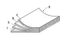
上記袋状容器2は、図2に示すように、厚さ12μのポリエステルフィルム4と厚さ9μのアルミニゥムホイル5と厚さ15μの延伸ナイロンフィルム6と厚さ60μ〜120μのポリエチレンフィルム7の積層フィルム8を素材として作られたフレキシブル性を有する構造である。この積層フィルム8は一例であって、フレキシブル性を有する構造であれば適当な積層フィルムが選択できる。
【0009】
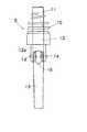
上記取出具3は、図3および図4に示すように、外面にねじ部10を設けた口部11と、接合面と接合面より下側に延びる支持部12aを有し口部11の下端に一体に形成された接合部12と、接合部12の支持部12aに回動自在に枢着された軸部13とを有する。軸部13の上部には半径方向外側に突き出るピン14,14が設けられ、接合部12の支持部12aには上記ピン14,14が嵌合する嵌合孔15,15が形成されている。
【0010】
上記取出具3は、接合部12の支持部12aに設けた嵌合孔15,15に軸部13のピン14,14を嵌合することで、接合部12に対して軸部13が回動自在となる。接合部12と軸部13の間には開口16が形成されており、この開口16は、液体容器1を反転することで導入口として作用し、充填された液状物を開口16を通して口部11から残すことなく外部に取り出す。
【0011】
上記取出具3は、支持部12aに対して軸部13がその回動角度を保持するように軸部13と支持部12aとの間のの嵌合抵抗が200g以上になるように設定されている。この嵌合抵抗は、充填された液状物により軸部13の支持部12aに対する回動角度位置が変位しない程度の抵抗を有する。嵌合抵抗は、取出具3の材質と、ピン14の外径と孔15の内径の差により決定される。
【0012】
上記軸部13は、下端部が先細り形状であり、軸部13が支持部12aに対して回動角度を保持している間、軸部13の先細り部が、外周面を袋状容器2の面に面接触し、軸部13の下端開口端面が袋状容器2の面に面接触しないようにしている。これは、回動する軸部13により袋状容器2の面が損傷しないようにするためである。
【0013】
つぎに、作用を説明する。
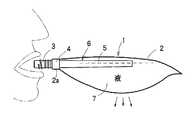
液状物を充填した液体容器1から液状物を取り出すには、液体容器1の軸部13を手で持って、取出具3の口部11に横方向の力を加えることで行う。この場合、軸部13と接合部12は回動自在に連結されているので、取出具3の口部11に横方向の力を加えると、口部11と接合部12は、軸部13に対して回動し、図5に示す回動角度位置を保持する。口部11の軸部13に対する回動角度位置の保持は、支持部12aと軸部13との間の嵌合抵抗を予め定めた設定値とすることで行われる。このように、口部11を軸部13に対して予め設定された回動角度位置を保持することで、液体容器1の口部11が液体容器1の液状物を飲もうとする子供、幼児、または病人の口に対して真っ直ぐに位置し、液体容器1の液状物を簡単かつ容易に飲用することができる。
【0014】
図6は本発明の他の実施の形態を示し、この実施の形態においては、取出具23の軸部24と接合部25の間に蛇腹部26を設け、接合部25より上方の部分を蛇腹部26を中心に回動するようにする。この場合、蛇腹部26に開口27を設けることができる。
【0015】
【発明の効果】
本発明によれば、フレキシブルフィルムで作った袋状容器の開口端に固着される取出具の軸部と接合部をピン手段により回動自在に連結したので、口部を袋状容器に対して曲げることにより充填された液状物をベッドで寝たままの状態で簡単に飲むことができ、また、軸部の下端部を先細り形状としたことで、軸部の下端面が袋状容器の内面に直接接触しないので軸部により袋状容器の内面が損傷することがない。
【図面の簡単な説明】
【図1】本発明により液体容器の一部を破いて示す斜視図。
【図2】本発明により液体容器の袋状容器を作る積層フィルムを示す図。
【図3】本発明により液体容器の取出具の正面図。
【図4】本発明により液体容器の取出具の側面図。
【図5】本発明により液体容器の使用状態を示す図。
【図6】本発明により液体容器の取出具の変形例を示す図。
【図7】従来の液体容器の使用状態を示す図。
【図8】従来の液体容器の使用状態を示す図。
【符号の説明】
1 液体容器
2 袋状容器
3 取出具
11 口部
12 接合部
13 軸部
14 ピン
15 孔[0001]
BACKGROUND OF THE INVENTION
The present invention relates to a liquid container in which a mouth portion is bent with respect to a bag-like container so that a filled liquid material can be easily drunk even while lying in a bed.
[0002]
[Prior art]
As this type of liquid container, as shown in FIG. 7, it has a bag-
In addition, as shown in FIG. 8, a
[0003]
[Problems to be solved by the invention]
In the liquid container shown in FIG. 7, since the shaft portion of the extraction tool extends in the vertical direction in the bag-like container, the extraction tool is placed with respect to the bag-like container so that the extraction tool faces the lateral direction from the bag-like container. If you try to rotate, the shaft end of the extractor hits the surface of the bag-like container with a small rotation angle of the extractor. It is difficult to use as a liquid container that can be drunk while sleeping.
[0004]
In addition, the liquid container shown in FIG. 7 is located in a straight line with respect to the joint portion with the mouth portion and the shaft portion of the extraction tool, so when trying to drink the liquid material filled with the liquid container sideways, Due to the weight of the filled liquid, the surface located on the lower side of the bag-like container swells downward, the axis of the extractor and the liquid level of the liquid filled in the liquid container are parallel, and the sick person is in bed If you try to drink while lying down, when the sick person's mouth is weakly closed, more liquid than necessary will flow out of the liquid container, and this liquid may enter the trachea of the sick person. is there.
[0005]
The liquid container shown in FIG. 8 can rotate the extraction tool with respect to the bag-shaped container, but when the extraction tool is rotated, the shaft opening end surface of the rotated extraction tool is brought into contact with the surface of the bag-shaped container. If the shaft opening is closed by the bag-shaped container due to surface contact, or the liquid material is reduced, the surfaces of the bag-shaped container may adsorb each other, and the liquid material can be drunk while lying in the bed. It is difficult to use as a type of liquid container.
The present invention has been made in view of the above-described points, and by bending the mouth portion with respect to the bag-like container, the liquid that can be easily drunk even in the state of lying on the bed. The purpose is to provide a container.
[0006]
[Problems to be solved by the invention]
The liquid container of the present invention includes a bag-like container made of a flexible film, and a takeout tool that includes a mouth portion, a joint portion, and a shaft portion, and the joint portion is fixed to the open end of the bag-like container. The lower end portion of the shaft portion is tapered, and the shaft portion and the joint portion of the extraction tool are rotatably connected by pin means.
[0007]
BEST MODE FOR CARRYING OUT THE INVENTION
The drawings of the embodiments of the present invention will be described below.
In FIG. 1,
[0008]
As shown in FIG. 2, the bag-
[0009]
As shown in FIGS. 3 and 4, the
[0010]
The
[0011]
The
[0012]
The
[0013]
Next, the operation will be described.
In order to take out the liquid material from the
[0014]
FIG. 6 shows another embodiment of the present invention. In this embodiment, a
[0015]
【The invention's effect】
According to the present invention, since the shaft portion and the joint portion of the extraction tool fixed to the opening end of the bag-like container made of a flexible film are rotatably connected by the pin means, the mouth portion is connected to the bag-like container. The liquid material filled by bending can be easily drunk while lying in the bed, and the lower end of the shaft is tapered so that the lower end of the shaft is the inner surface of the bag-like container. The inner surface of the bag-like container is not damaged by the shaft portion.
[Brief description of the drawings]
FIG. 1 is a perspective view showing a liquid container broken according to the present invention.
FIG. 2 is a view showing a laminated film for making a bag-like container of a liquid container according to the present invention.
FIG. 3 is a front view of a liquid container take-out device according to the present invention.
FIG. 4 is a side view of an extraction tool for a liquid container according to the present invention.
FIG. 5 is a diagram showing a use state of a liquid container according to the present invention.
FIG. 6 is a view showing a modification of the liquid container takeout tool according to the present invention.
FIG. 7 is a view showing a use state of a conventional liquid container.
FIG. 8 is a view showing a use state of a conventional liquid container.
[Explanation of symbols]
DESCRIPTION OF
Claims (2)
Translated fromJapanesePriority Applications (5)
| Application Number | Priority Date | Filing Date | Title |
|---|---|---|---|
| JP12055599AJP3614706B2 (en) | 1999-04-27 | 1999-04-27 | Liquid container |
| US09/392,790US6332564B2 (en) | 1999-04-27 | 1999-09-09 | Liquid container |
| DE69922341TDE69922341T2 (en) | 1999-04-27 | 1999-09-10 | liquid container |
| EP99307177AEP1048588B1 (en) | 1999-04-27 | 1999-09-10 | Liquid Container |
| HK01101350.1AHK1032222B (en) | 1999-04-27 | 2001-02-23 | Liquid container |
Applications Claiming Priority (1)
| Application Number | Priority Date | Filing Date | Title |
|---|---|---|---|
| JP12055599AJP3614706B2 (en) | 1999-04-27 | 1999-04-27 | Liquid container |
Publications (2)
| Publication Number | Publication Date |
|---|---|
| JP2000309345A JP2000309345A (en) | 2000-11-07 |
| JP3614706B2true JP3614706B2 (en) | 2005-01-26 |
Family
ID=14789214
Family Applications (1)
| Application Number | Title | Priority Date | Filing Date |
|---|---|---|---|
| JP12055599AExpired - LifetimeJP3614706B2 (en) | 1999-04-27 | 1999-04-27 | Liquid container |
Country Status (4)
| Country | Link |
|---|---|
| US (1) | US6332564B2 (en) |
| EP (1) | EP1048588B1 (en) |
| JP (1) | JP3614706B2 (en) |
| DE (1) | DE69922341T2 (en) |
Families Citing this family (22)
| Publication number | Priority date | Publication date | Assignee | Title |
|---|---|---|---|---|
| DE10127895A1 (en)* | 2001-06-08 | 2002-12-12 | Indag Gmbh | Closing element for packaging for holding liquid or pasty goods |
| US6905314B2 (en) | 2001-10-16 | 2005-06-14 | Baxter International Inc. | Pump having flexible liner and compounding apparatus having such a pump |
| US6769231B2 (en) | 2001-07-19 | 2004-08-03 | Baxter International, Inc. | Apparatus, method and flexible bag for use in manufacturing |
| CN1292963C (en)* | 2001-08-27 | 2007-01-03 | 李贞旻 | Spout assembly for liquid container |
| AU2002367107B2 (en) | 2001-12-25 | 2006-08-10 | Chokoku Plast Corporation | Self-standing packaging bag, packaging body, web roll, and manufacturing method therefor |
| US20040144799A1 (en)* | 2003-01-24 | 2004-07-29 | Baxter International Inc. | Liquid dispenser and flexible bag therefor |
| US7007824B2 (en) | 2003-01-24 | 2006-03-07 | Baxter International Inc. | Liquid dispenser and flexible bag therefor |
| JP3604685B1 (en)* | 2003-10-20 | 2004-12-22 | 株式会社細川洋行 | Packaging container |
| GB0324907D0 (en)* | 2003-10-24 | 2003-11-26 | Interbrew Sa | Alcohol beverage bag |
| BRPI0509572B1 (en)* | 2004-03-31 | 2022-09-27 | Swimc Llc | APPLIANCE FOR REMOVING PAINT FROM A CONTAINER AND LID FOR A PLASTIC CONTAINER FOR STORAGE OF LIQUID COATING MATERIALS |
| JP4525977B2 (en)* | 2004-08-31 | 2010-08-18 | 株式会社吉野工業所 | Flexible container |
| US7331489B2 (en)* | 2004-11-19 | 2008-02-19 | Glynntech, Inc. | Metered dose squeeze dispenser having a dip tube with a rotatable leg |
| US7243478B2 (en)* | 2005-04-04 | 2007-07-17 | Walker-Dawson Interests, Inc. | Vacuum system manifold and related methods |
| JP2006327651A (en)* | 2005-05-27 | 2006-12-07 | Hosokawa Yoko Co Ltd | Liquid container |
| US8474665B2 (en)* | 2008-07-24 | 2013-07-02 | Sports Pouch Beverage Co., Inc. | Re-sealable spigot for a collapsible beverage container |
| US8459512B2 (en)* | 2008-07-24 | 2013-06-11 | Sports Pouch Beverage Co., Inc. | Re-sealable spigot for a collapsible beverage container |
| US9321558B2 (en)* | 2012-09-19 | 2016-04-26 | Perimeter Brand Packaging, Llc | Insert assembly for beverage container |
| USD711251S1 (en) | 2013-04-16 | 2014-08-19 | Steven Epstein | Flat bottom tapped pouch with non-tapered side gussets |
| USD724953S1 (en) | 2013-04-16 | 2015-03-24 | Steven Epstein | Flat bottom tapped pouch with tapered side gussets |
| US9821284B2 (en)* | 2014-08-05 | 2017-11-21 | Jpro Dairy International, Inc. | Shaker bag mixing assembly |
| USD940515S1 (en)* | 2020-02-24 | 2022-01-11 | Caiyun Li | Fresh-keeping bag |
| WO2022168653A1 (en)* | 2021-02-05 | 2022-08-11 | 株式会社フジシール | Pouch |
Family Cites Families (13)
| Publication number | Priority date | Publication date | Assignee | Title |
|---|---|---|---|---|
| US3645424A (en)* | 1969-11-06 | 1972-02-29 | Osmose Wood Preserving Co | Dip tube for aerosol dispenser |
| JPS5550939U (en)* | 1978-09-28 | 1980-04-03 | ||
| US5647511A (en)* | 1984-03-29 | 1997-07-15 | Liqui-Box Corporation | Collapsed bag with evacuation channel form unit |
| JPH0221399Y2 (en)* | 1985-02-14 | 1990-06-08 | ||
| US4703892A (en)* | 1986-05-29 | 1987-11-03 | Nadel & Sons Toy Corp. | Water shooting amusement device |
| JPH074230Y2 (en)* | 1986-08-21 | 1995-02-01 | 株式会社細川洋行 | Liquid filling container |
| US4830235A (en)* | 1988-02-01 | 1989-05-16 | Miller Michael D | Siphon tube apparatus |
| US5797522A (en)* | 1992-11-10 | 1998-08-25 | Evnx Technologies, Inc. | Aerosol spray dispenser with swinging downtube |
| IT1273281B (en)* | 1994-03-31 | 1997-07-07 | Gianpaolo Belloli | PROCEDURE FOR THE CREATION OF PLASTICIZED SHEET CONTAINERS AND CONTAINERS SO OBTAINED |
| US5522548A (en)* | 1994-10-06 | 1996-06-04 | Summit Packaging Systems, Inc. | Aerosol valve having swivelly mounted dip tube |
| US5699936A (en)* | 1995-09-08 | 1997-12-23 | Sercomp Corporation | Liquid dispensing system |
| WO1998001355A1 (en)* | 1996-07-04 | 1998-01-15 | Mikuni Plastics Co., Ltd. | Food container |
| US6000848A (en)* | 1997-07-08 | 1999-12-14 | Massioui; Farid El | Fluid package with closure |
- 1999
- 1999-04-27JPJP12055599Apatent/JP3614706B2/ennot_activeExpired - Lifetime
- 1999-09-09USUS09/392,790patent/US6332564B2/ennot_activeExpired - Lifetime
- 1999-09-10DEDE69922341Tpatent/DE69922341T2/ennot_activeExpired - Lifetime
- 1999-09-10EPEP99307177Apatent/EP1048588B1/ennot_activeExpired - Lifetime
Also Published As
| Publication number | Publication date |
|---|---|
| HK1032222A1 (en) | 2001-07-13 |
| DE69922341T2 (en) | 2005-12-01 |
| EP1048588A1 (en) | 2000-11-02 |
| JP2000309345A (en) | 2000-11-07 |
| EP1048588B1 (en) | 2004-12-01 |
| US20010027984A1 (en) | 2001-10-11 |
| DE69922341D1 (en) | 2005-01-05 |
| US6332564B2 (en) | 2001-12-25 |
Similar Documents
| Publication | Publication Date | Title |
|---|---|---|
| JP3614706B2 (en) | Liquid container | |
| EP1858475B1 (en) | Closing device with integrated rotary closure for feeding bottle and bottle | |
| JP4612258B2 (en) | Device for extracting substances for making beverages | |
| JP5815413B2 (en) | Inserts for beverage cups | |
| EP0122809A1 (en) | Dispensing container | |
| JP2005205178A (en) | Spoon | |
| CN218607394U (en) | Square flip feeding bottle | |
| CN206659732U (en) | Toilet brush and the toilet seat brush stands with lateral cover rotary | |
| CN215382978U (en) | Milk tea cup cover structure capable of storing straws | |
| CN215533448U (en) | Water cup with storage function | |
| JP4619514B2 (en) | Mouthpiece device | |
| JP2988655B2 (en) | Cap for spout of container cap | |
| CN221785896U (en) | Cup cover with spoon | |
| CN213737650U (en) | Powder storage device for pharmacy | |
| JPH059090Y2 (en) | ||
| JP2004049856A5 (en) | ||
| KR200238610Y1 (en) | Envelope hanger | |
| JP3029128U (en) | Container with lid for bags of liquids | |
| JPH0126300Y2 (en) | ||
| JPH0621485Y2 (en) | Mug type baby bottle | |
| JPH066052Y2 (en) | Draw cap | |
| JP2004026304A (en) | Can for drinks | |
| TW200528369A (en) | A foldable frame-type bag-holding device for expectoration or vomit | |
| JP3023304U (en) | Garbage container lid | |
| JP2004049856A (en) | Cup provided with straw |
Legal Events
| Date | Code | Title | Description |
|---|---|---|---|
| A977 | Report on retrieval | Free format text:JAPANESE INTERMEDIATE CODE: A971007 Effective date:20040528 | |
| A131 | Notification of reasons for refusal | Free format text:JAPANESE INTERMEDIATE CODE: A131 Effective date:20040604 | |
| A521 | Request for written amendment filed | Free format text:JAPANESE INTERMEDIATE CODE: A523 Effective date:20040803 | |
| TRDD | Decision of grant or rejection written | ||
| A01 | Written decision to grant a patent or to grant a registration (utility model) | Free format text:JAPANESE INTERMEDIATE CODE: A01 Effective date:20041001 | |
| A61 | First payment of annual fees (during grant procedure) | Free format text:JAPANESE INTERMEDIATE CODE: A61 Effective date:20041027 | |
| R150 | Certificate of patent or registration of utility model | Free format text:JAPANESE INTERMEDIATE CODE: R150 | |
| FPAY | Renewal fee payment (event date is renewal date of database) | Free format text:PAYMENT UNTIL: 20101112 Year of fee payment:6 | |
| FPAY | Renewal fee payment (event date is renewal date of database) | Free format text:PAYMENT UNTIL: 20111112 Year of fee payment:7 | |
| FPAY | Renewal fee payment (event date is renewal date of database) | Free format text:PAYMENT UNTIL: 20121112 Year of fee payment:8 | |
| FPAY | Renewal fee payment (event date is renewal date of database) | Free format text:PAYMENT UNTIL: 20121112 Year of fee payment:8 | |
| FPAY | Renewal fee payment (event date is renewal date of database) | Free format text:PAYMENT UNTIL: 20131112 Year of fee payment:9 | |
| R250 | Receipt of annual fees | Free format text:JAPANESE INTERMEDIATE CODE: R250 | |
| R250 | Receipt of annual fees | Free format text:JAPANESE INTERMEDIATE CODE: R250 | |
| R250 | Receipt of annual fees | Free format text:JAPANESE INTERMEDIATE CODE: R250 | |
| R250 | Receipt of annual fees | Free format text:JAPANESE INTERMEDIATE CODE: R250 | |
| R250 | Receipt of annual fees | Free format text:JAPANESE INTERMEDIATE CODE: R250 | |
| EXPY | Cancellation because of completion of term |