JP3610341B2 - Network device and remote control relay server - Google Patents
Network device and remote control relay serverDownload PDFInfo
- Publication number
- JP3610341B2 JP3610341B2JP2002041833AJP2002041833AJP3610341B2JP 3610341 B2JP3610341 B2JP 3610341B2JP 2002041833 AJP2002041833 AJP 2002041833AJP 2002041833 AJP2002041833 AJP 2002041833AJP 3610341 B2JP3610341 B2JP 3610341B2
- Authority
- JP
- Japan
- Prior art keywords
- remote control
- permission
- related information
- network device
- control relay
- Prior art date
- Legal status (The legal status is an assumption and is not a legal conclusion. Google has not performed a legal analysis and makes no representation as to the accuracy of the status listed.)
- Expired - Fee Related
Links
Images


Classifications
- H—ELECTRICITY
- H04—ELECTRIC COMMUNICATION TECHNIQUE
- H04L—TRANSMISSION OF DIGITAL INFORMATION, e.g. TELEGRAPHIC COMMUNICATION
- H04L63/00—Network architectures or network communication protocols for network security
- H04L63/06—Network architectures or network communication protocols for network security for supporting key management in a packet data network
- H—ELECTRICITY
- H04—ELECTRIC COMMUNICATION TECHNIQUE
- H04L—TRANSMISSION OF DIGITAL INFORMATION, e.g. TELEGRAPHIC COMMUNICATION
- H04L63/00—Network architectures or network communication protocols for network security
- H04L63/08—Network architectures or network communication protocols for network security for authentication of entities
- H04L63/083—Network architectures or network communication protocols for network security for authentication of entities using passwords
- H—ELECTRICITY
- H04—ELECTRIC COMMUNICATION TECHNIQUE
- H04W—WIRELESS COMMUNICATION NETWORKS
- H04W12/00—Security arrangements; Authentication; Protecting privacy or anonymity
- H04W12/04—Key management, e.g. using generic bootstrapping architecture [GBA]
- H04W12/041—Key generation or derivation
- H—ELECTRICITY
- H04—ELECTRIC COMMUNICATION TECHNIQUE
- H04W—WIRELESS COMMUNICATION NETWORKS
- H04W12/00—Security arrangements; Authentication; Protecting privacy or anonymity
- H04W12/06—Authentication
- H04W12/068—Authentication using credential vaults, e.g. password manager applications or one time password [OTP] applications
Landscapes
- Engineering & Computer Science (AREA)
- Computer Security & Cryptography (AREA)
- Computer Networks & Wireless Communication (AREA)
- Signal Processing (AREA)
- Computer Hardware Design (AREA)
- Computing Systems (AREA)
- General Engineering & Computer Science (AREA)
- Computer And Data Communications (AREA)
- Data Exchanges In Wide-Area Networks (AREA)
- Small-Scale Networks (AREA)
- Telephonic Communication Services (AREA)
- Information Transfer Between Computers (AREA)
Description
Translated fromJapanese【0001】
【発明の属する技術分野】
本発明は、ネットワークに接続されたネットワーク機器を、電子機器から、遠隔制御中継サーバを経由して、遠隔制御するための遠隔制御中継方法および遠隔制御システムに関する。
【0002】
【従来の技術】
近年、様々な家庭電化製品やコンピュータ周辺機器がネットワークに接続可能になりつつある。例えば、プリンタ、プロジェクタ、スキャナ、デジタルカメラ及びデジタルビデオカメラなどをネットワーク対応にする検討がなされている。これらのネットワーク対応機器は、LANだけでなく、インターネットのようなWANにも接続されるようになることが期待されている。
【0003】
とりわけ、これらのネットワーク対応機器を携帯電話やPDAなどの携帯端末から遠隔制御したいとの要望が高まりつつある。この要望に応えるには、インターネット上で操作されるネットワーク対応機器にIP(Internet Protocol)アドレスを割り当て、さらに、URL(Uniform Resource Locator)やIPアドレスを一般公開する必要がある。
【0004】
【発明が解決しようとする課題】
上記の技術によれば、ネットワーク機器のURLやIPアドレスを知り得た者であれば誰であっても、その機器を勝手に操作することが可能となる。例えば、留守宅を監視するシステムを従来技術で構築した場合、システムを構築した留守宅の所有者以外の不特定多数者が留守宅の様子を見ることが可能となってしまう。これでは、プライバシーが侵害されるだけでなく、留守であることを悪意の第三者に知られるおそれもあり、盗難被害を助長しかねない。
【0005】
このようにインターネットを利用した機器操作システムまたはサービスには、ネットワークに接続された制御対象機器のURLまたはIPアドレスを公開することにより、意図しない利用者に制御対象機器を勝手に使用されてしまうという問題がある。
【0006】
そこで、本発明は、ネットワークに接続された制御対象機器のURLまたはIPアドレスを操作者に公開することなく、当該制御対象機器を操作可能にする遠隔制御中継方法および遠隔制御システムを提供することを目的とする。
【0007】
【課題を解決するための手段】
本願発明は、第1の観点によれば、
ネットワークに接続されたネットワーク機器を、電子機器から、遠隔制御中継サーバを経由して、遠隔制御するための遠隔制御中継方法であって、
前記遠隔制御中継サーバは、前記遠隔制御を許可するための許可関連情報を生成し、生成した該許可関連情報を前記ネットワーク機器に送信し、
前記ネットワーク機器は、前記許可関連情報を前記遠隔制御中継サーバから受信して表示し、
前記電子機器は、前記ネットワーク機器に表示された前記許可関連情報が入力されると、入力された該許可関連情報を前記遠隔制御中継サーバに送信し、
前記遠隔制御中継サーバは、前記許可関連情報を前記電子機器から受信し、受信した該許可関連情報が、生成した前記許可関連情報と一致する場合に、前記許可関連情報に対応するネットワーク機器に対して前記電子機器からの動作指示に基づいた動作命令を発行することを特徴とする遠隔制御中継方法が提供される。
【0010】
本願発明の第2の観点によれば、
ネットワークに接続されたネットワーク機器を、電子機器から、遠隔制御中継サーバを経由して、遠隔制御するための遠隔制御システムであって、
前記遠隔制御システムは、前記ネットワーク機器と前記遠隔制御中継サーバとを含み、
前記遠隔制御中継サーバは、
前記遠隔制御を許可するための許可関連情報を生成する生成手段と、
生成した前記許可関連情報を前記ネットワーク機器に送信する送信手段と、
前記ネットワーク機器において受信されて表示された前記許可関連情報を前記電子機器から受信する第1の受信手段と、
受信した前記許可関連情報が、生成した前記許可関連情報と一致する場合に、前記許可関連情報に対応するネットワーク機器に対する動作命令を、前記電子機器から送信される動作指示に基づいて発行する発行手段と
を含み、
前記ネットワーク機器は、
前記許可関連情報を前記遠隔制御中継サーバから受信する第2の受信手段と、
受信した前記許可関連情報を表示する表示手段と、
前記遠隔制御中継サーバにより発行された前記動作命令を受け付ける受付手段と、
受け付けた前記動作命令に応じた処理を実行する実行手段と
を含む、遠隔制御システムが提供される。
【0013】
本願発明の第3の観点によれば、
ネットワークに接続されたネットワーク機器を、電子機器から、遠隔制御中継サーバを経由して、遠隔制御するための遠隔制御中継方法であって、
前記ネットワーク機器は、前記遠隔制御を許可するための許可関連情報を生成して表示する一方で、生成した該許可関連情報を前記遠隔制御中継サーバに送信し、
前記電子機器は、前記ネットワーク機器に表示された前記許可関連情報が入力されると、入力された該許可関連情報を前記遠隔制御中継サーバに送信し、
前記遠隔制御中継サーバは、前記許可関連情報を前記ネットワーク機器から受信する一方で、前記電子機器から前記許可関連情報を受信し、受信した双方の該許可関連情報が一致すると、前記許可関連情報に対応するネットワーク機器に対して前記電子機器からの動作指示に基づいた動作命令を発行する
ことを特徴とする遠隔制御中継方法が提供される。
【0018】
本願発明の第4の観点によれば、
ネットワークに接続されたネットワーク機器を、電子機器から、遠隔制御中継サーバを経由して、遠隔制御するための遠隔制御システムであって、
前記遠隔制御システムは、前記ネットワーク機器と前記遠隔制御中継サーバとを含み、
前記ネットワーク機器は、
前記遠隔制御を許可するための許可関連情報を生成する生成手段と、
生成した前記許可関連情報を前記遠隔制御中継サーバに送信する送信手段と、
生成した前記許可関連情報を表示する表示手段と、
前記遠隔制御中継サーバにより発行された動作命令を受け付ける受付手段と、
受け付けた前記動作命令に応じた処理を実行する実行手段と
を含み、
前記遠隔制御中継サーバは、
前記ネットワーク機器から前記許可関連情報を受信する第1の受信手段と、
前記ネットワーク機器において表示された前記許可関連情報を前記電子機器から受信する第2の受信手段と、
受信した双方の前記許可関連情報が一致する場合に、前記許可関連情報に対応するネットワーク機器に対する前記動作命令を前記電子機器からの動作指示に基づいて発行する発行手段と
を含む、遠隔制御システムが提供される。
【0020】
【発明の実施の形態】
以下に本願発明の一実施形態を示す。もちろん以下の実施形態は、いわゆる当業者による実施を容易にするために提供されるものであり、特許請求の範囲によって確定される本願発明の技術的範囲に含まれるほんの一部の実施形態にすぎない。従って、本願明細書に直接的に記載されていない実施形態であっても、技術思想が共通する限り本願発明の技術的範囲に包含されることは当業者にとって自明であろう。
【0021】
なお、便宜上複数の実施形態を記載するが、これらは個別に発明として成立するだけでなく、もちろん、複数の実施形態を適宜組み合わせることでも発明が成立することは、当業者であれば容易に理解できよう。
【0022】
[第1の実施形態]
<システム構成>
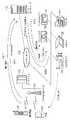
図1は、第1の実施形態に係る遠隔制御システムの構成図である。本システムの制御主体は、携帯電話101やPDA(Personal Digital Assistance)102などの携帯端末である。携帯電話101は、電話としての基本機能の他にブラウザ機能も搭載しており、携帯電話網を経由してインターネット130に接続できる。PDA102は、個人用の携帯情報端末であり、例えば、手のひらに収まるくらいの大きさの電子機器である。携帯電話101と同様に、ブラウザ機能を搭載し、内部の通信インタフェース又は外部の通信インタフェースによりネットワークに接続される。これらは、携帯電話の基地局などのアクセスポイント131に無線回線を介して接続する。アクセスポイント131は、携帯電話網又はパケット網を介してゲートウェイ132に接続されている。ゲートウェイ132は、携帯電話網又はパケット網とインターネット130とを中継する装置である。
【0023】
インターネット130には、サーバコンピュータ110が接続されている。サーバコンピュータ110は、ネットワークに接続されたクライアントコンピュータなどから送信されるオブジェクト要求に応答する機能など、一般的なウェブサーバとしての機能を有する。本実施形態では、さらに、アクセスキーを生成する機能、アクセスキーと機器120〜124のIPアドレスまたはURLを管理する機能、システム利用者の情報を管理する機能、前述の管理情報をもとに認証処理を行う機能、及び各機器をコントロールするための命令を発行する機能を有する。
【0024】
インターネット130には、制御対象となるネットワーク機器の一例であるプロジェクタ120、デジタルカメラ121、ビデオカメラ122、スキャナ123及びプリンタ124も接続されている。これらの機器は、それぞれの固有な機能の他にネットワークに接続しデータ通信を実行する機能、サーバコンピュータ110から送信されてきたメッセージを解釈し、各機器に対応したドライバを制御する機能、サーバコンピュータ110からアクセスキーを取得する機能及び前記アクセスキーを表示手段に表示する機能を有する。
【0025】
このように、この遠隔制御システムでは、ネットワークに接続された機器120〜124を、利用者が使用する携帯電話101またはPDA102などからサーバコンピュータ110を経由して遠隔制御する場合を想定している。
【0026】
<ハードウエア構成>
図2は、本実施形態に係る各装置のハードウエア構成の一例を示している。携帯端末101及びPDA102は、CPU 201、ROM 202、RAM 203、入力装置204、LCD205及び通信IF206等を備える。CPU201は、例えば、電源投入時はROM202に記憶されたブートプログラムに従って起動し、ROM202等からOSや後述のアプリケーションプログラムをRAM203にロードすることで携帯電話やPDAとして機能する。入力装置204は、キーボード、ポインティングデバイス又はタッチパネルなどの入力手段である。LCD205は、液晶表示デバイスであり、ネットワーク機器の動作結果など種々の情報を表示する。通信IF206は、無線通信デバイスを含む通信装置であり、携帯電話の規格に準拠して動作する。
【0027】
携帯端末サーバコンピュータ110は、CPU 211、ROM 212、RAM 213、HDD217及び通信IF216等を備える。CPU211は、例えば、電源投入時はROM212に記憶されたブートプログラムに従って起動し、ROM212やHDD217等からOSや後述のアプリケーションプログラムをRAM213にロードすることでサーバとして機能する。通信IF216は、インターネット接続するためのネットワークカード(NIC)などの通信装置である。なお、HDD217はハードディスクなどの大容量の記憶装置であり、本実施形態にかかるクライアント管理データやアクセスキー管理データを記憶している。
【0028】
ネットワーク機器120〜124は、ネットワークへの接続機能を備えた機器であり、例えば、プロジェクタ120、デジタルカメラ121、ビデオカメラ122、スキャナ123及びプリンタ124などである。ネットワーク機器120等は、CPU 221、ROM 222、RAM 223、LCD225、通信IF226及び固有機構228等を備える。
【0029】
CPU221は、例えば、電源投入時はROM222に記憶されたブートプログラムに従って起動し、ROM222等からOSや後述のアプリケーションプログラムをRAM223にロードすることでデジタルカメラ等として機能する。LCD225は、液晶表示デバイスであり、例えば、アクセスキーに関する情報を表示する。通信IF226は、インターネット接続するためのネットワークカードなどの通信装置である。固有機構228は、各ネットワーク機器に固有の処理機構である。例えば、プロジェクタ120の場合は、画像投影に関する光学系や光学系を駆動するための駆動機構などである。デジタルカメラ121の場合は、CCDなどの画像読み取り装置、画像変換回路、露出制御回路、ストロボ回路などである。ビデオカメラ122であれば、映像記録用の光学系、CCD、テープ記録機構などである。スキャナ123であれば、画像読み取り機構などである。プリンタ124の場合は、PDL言語解析回路や画像形成機構などが該当しよう。
【0030】
<ソフトウエア構成>
図3は、本実施形態に係るサーバコンピュータ110などのアプリケーション・モジュールの一例を示している。
【0031】
サーバコンピュータ110は、アクセス・コントロール・モジュール310、アクセスキー生成モジュール311、ウェブサーバ312、機器操作モジュール313等を含んでいる。
【0032】
アクセス・コントロール・モジュール310は、利用者(以下クライアントと称す。)の認証を行い、当該クライアントがサーバコンピュータ110を経由して各種機器120〜124を操作する権限があるか否かを判断するプログラムモジュールである。例えば、携帯電話101やPDA102から送信されてきたクライアント名、パスワード及びアクセスキーに基づいて、アクセスキー管理テーブル500を検索することで、上記の認証処理を実行する。また、アクセスキーに基づいて、アクセスキー管理テーブル500を検索することで、当該アクセスキーに対応するネットワーク機器のIPアドレスやURLを特定することができる。
【0033】
アクセスキー生成モジュール311は、機器120〜124からのアクセスキー作成要求に基づいて、動的に任意のアクセスキーを生成し、機器のIPアドレスまたはURLと対応付けて生成されたアクセスキーをアクセスキー管理テーブル500(図5)に格納する。さらに、アクセスキー管理テーブル500には、クライアント名及びパスワードを格納してもよい。なお、アクセスキーは後述するアクセスキー管理テーブル500に存在する他のアクセスキーと重複がないよう、つまりユニークとなるようにアクセスキー生成モジュール311により生成される。
【0034】
ウェブサーバ312は、例えば、HTTP(Hyper Text Transfer Protocol)サーバであり、他のコンピュータシステムなどと通信経路を確保し、クライアントからのオブジェクト要求に応じてオブジェクトを送信したり、オブジェクトを受信したりする機能を有している。例えば、フリーウェアのApacheなどを用いることができる。
【0035】
機器操作モジュール313は、クライアントからの動作指示に応じて各機器を操作するための動作命令を機器に発行する機能を有している。さらに、特定されたネットワーク機器に応じた操作画面を携帯電話101等に提供する。
【0036】
次に、ネットワーク機器120〜124内のアプリケーション・モジュールを説明する。機器120〜124は、機器固有の機能を実現するためのモジュールを備えているが詳細は省略する。各ネットワーク機器120〜124は、それぞれ、コントロールサーバ321、アクセスキー表示モジュール322から構成される。
【0037】
コントロールサーバ321は、ウェブサーバ312と同様の機能を有する。アクセスキー表示モジュール322は、HTTPのクライアントとしてウェブサーバ312に対しオブジェクト要求を作成する機能、オブジェクト要求等を送信する機能、ウェブサーバ312からのオブジェクトを受信する機能、LCD225などの出力装置に受信されたアクセスキーを出力させる機能を有する。なお、固有機構228により、アクセスキーを出力してもよい。例えば、プロジェクタ120であれば、スクリーンにアクセスキーを表示したり、プリンタ124であれば、アクセスキーを印刷したりしてもよい。
【0038】
<システム処理の流れ>
図4に本実施形態に係る処理シーケンス図を示す。ネットワーク機器120〜124の電源をONにすると、アクセスキー表示モジュール322が起動される。ステップS401において、アクセスキー表示モジュール322は、コントロールサーバ321にサーバコンピュータ110のIPアドレスやURLを渡し、アクセスキーの生成要求を送信するよう命令する。コントロールサーバ321は、サーバコンピュータ110にアクセス要求を送信する。
【0039】
ステップS402において、サーバコンピュータ110のウェブサーバ312は、このアクセス要求に応答し、応答メッセージを送信する。応答メッセージは、コントロールサーバ321により受信される。
【0040】
ステップS403において、コントロールサーバ321は、アクセスキーの生成要求を送信する。ウェブサーバ312は、当該生成要求を受信し、アクセスキー生成モジュール311を起動する。なお、前記生成要求を送信した機器のIPアドレスは、パケットのヘッダから取得できる。また、そのURLもネットワーク機器のコントロールサーバ321に対し、URLに関する情報を送信するよう要求することで取得してもよい。取得されたIPアドレスやURLもアクセスキー生成モジュール311に渡される。
【0041】
ステップS404において、起動されたアクセスキー生成モジュール311は、動的にアクセスキーを生成する。動的にアクセスキーを生成するのは、アクセスキーを頻繁に変更することで、悪意の第三者によるアクセスキーの解読を抑制するためである。なお、セキュリティのレベルを下げてもよければ、静的にアクセスキーを生成してもよい。
【0042】
ステップS405において、アクセスキー生成モジュール311は、アクセスキーの生成要求を送信してきたネットワーク機器のIPアドレスやURLを、生成されたアクセスキーと対応付けて、アクセスキー管理テーブル500のキーテーブル502に格納する。
【0043】
図5は、本実施形態に係るアクセスキー管理テーブル500の概念図である。アクセスキー管理テーブル500は、クライアントテーブル501とキーテーブル502を含んでいる。クライアントテーブル501とキーテーブル502とも、読み書き可能であり、かつ、検索可能である。クライアントテーブル501は、クライアント名とパスワードを格納するテーブルである。キーテーブル502は、アクセスキーの生成要求を送信してきた機器のIPアドレス又はURLと生成されたアクセスキーを格納するテーブルである。クライアントテーブル301とキーテーブル302のそれぞれのレコードは、アクセスキー生成モジュール311により関連付け処理と削除処理が実行される。
【0044】
ステップS406において、アクセスキー生成モジュール311は、ウェブサーバ312を介してアクセスキーを送信する。
【0045】
ステップS407において、コントロールサーバ321は、アクセスキーを受信し、アクセスキー表示モジュール322に渡す。アクセスキー表示モジュール322は、このアクセスキーをLCD225などに表示させる。
【0046】
図6は、LCD225に表示されたアクセスキーの一例を示す図である。先に説明したように、固有機構228により出力してもよい。出力されたアクセスキーは、携帯電話101やPDA102のクライアントにより確認される。
【0047】
ステップS408において、携帯電話101またはPDA102のブラウザ300が起動される。さらに、利用者により入力されたサーバコンピュータ110のURLやIPアドレスに基づいて、サーバ100にアクセス要求を送信する。
【0048】
ステップS409において、ウェブサーバ312は、図7に示されるような認証画面情報を送信する。認証画面情報は、例えば、HTMLを用いて記述されている。また、クライアント名、パスワード及びアクセスキーを入力できるようになっている。
【0049】
ステップS410において、ブラウザ300は、画面情報を受信して解析し、LCD205に図7に例示された画面を表示する。表示された画面に応じて、クライアント名、パスワード及びネットワーク機器に表示されたアクセスキーが入力される。
【0050】
ステップS411において、送信ボタンがクリックされると、ブラウザ300は入力された認証情報をアクセス・コントロール・モジュール310に送信する。
【0051】
ステップS412において、ウェブサーバ312は、クライアント名、パスワード及びアクセスキーを含む認証要求を受信すると、アクセス・コントロール・モジュール310を起動し、クライアント名、パスワード及びアクセスキーを渡す。起動されたアクセス・コントロール・モジュール312は、受信されたクライアント名及びパスワードに基づいて、クライアントテーブル501を検索して、正規のクライアントである否かを判定する。正規のクライアントであれば、S413に進み、正規のクライアントであれば、アクセスの拒否情報を送信する。
【0052】
ステップS413において、アクセス・コントロール・モジュール312は、受信されたアクセスキーと一致するレコードをキーテーブル502から検索する。これによりネットワーク機器のIPアドレスもしくはURLが特定される。さらに、一致したレコードと、先のクライアント名及びパスワードのレコードとの対応関係も作成する。アクセス・コントロール・モジュール312は、さらに、機器操作モジュール313を起動し、特定されたネットワーク機器のIPアドレスもしくはURLを渡す。
【0053】
ステップS414において、機器操作モジュール313は、特定されたネットワーク機器にアクセス要求を送信する。
【0054】
ステップ415において、コントロールサーバ321は、アクセス要求に返信すべくアクセス応答を送信する。アクセス応答は、ネットワーク機器を操作するためのメニュー画面に関する情報であってもよい。
【0055】
ステップS416において、機器操作モジュール313は、アクセス応答の受信によりネットワーク機器の動作状態を確認する。さらに、動作指示の受付を開始すべく、機器操作モジュール313は、ネットワーク機器を操作するためのメニュー画面情報を送信する。メニュー画面情報は、予めHTML形式などで作成されたファイルであってもよいし、ネットワーク機器から送信されてきたファイルであってもよい。以降、この画面から機器操作が可能となる。
【0056】
ステップS417において、ブラウザ300は、受信したメニュー画面をLCD205に表示させる。さらに、入力装置204から入力された動作指示に関する情報を送信する。
【0057】
ステップS418において、機器操作モジュール313は、受信した動作指示に関する情報に基づいて、ネットワーク機器に対応した動作命令を発行する。
【0058】
ステップS419において、機器操作モジュール313は、動作命令に関する情報をコントロールサーバ321に送信する。
【0059】
ステップS420において、コントロールサーバ321は、動作命令に関する情報を受信すると固有機構制御モジュール323を起動する。固有機構制御モジュール323は、動作命令に基づいて所定の処理を実行する。プリンタ124であれば、任意の情報を印刷するが如くである。また、デジタルカメラ121であれば、静止画像を記録するが如くである。
【0060】
ステップS421において、固有機構制御モジュール323は、画像情報などの動作結果情報を送信する。
【0061】
ステップS422において、機器操作モジュール313は、受信した動作結果情報を携帯端電話101などに転送する。もちろん、動作結果を含んだ画面情報を作成してから送信してもよい。
【0062】
ステップS423において、ブラウザ323は、受信した動作結果情報をLCD205に表示させる。
【0063】
以上のように、本実施形態では、予め登録されているアクセスキーとクライアントから送信されてきたアクセスキーとを比較することにより、制御対象となるネットワーク機器を特定することができる。すなわち、サーバコンピュータ110のIPアドレスもしくはURLをクライアントが知っていれば、各ネットワーク機器120〜124の個別のIPアドレスもしくはURLを知らなくても、各ネットワーク機器120〜124を操作できる。そのため、各ネットワーク機器120〜124の個別のIPアドレスもしくはURLをクライアントに公開する必要がないため、ネットワーク機器120〜124を悪意のクライアントに利用される可能性を低減できよう。また、正しいアクセスキーを把握している利用者のみに遠隔制御を限定することもできる。さらに、クライアント名やパスワードにより認証処理を実行すれば、より安全性を高めることができる。アクセスキーは、サーバにより動的に生成され、しかも、クライアントが所有するネットワーク機器から出力されるため、悪意の第三者がアクセスキーを特定することは困難であろう。従って、より安全性を確保することが可能となる。
【0064】
[第2の実施形態]
<システム構成>
図8は、第2の実施形態に係るシステム構成の一例を示す図である。第1の実施形態と共通する説明については、当業者が本実施形態を理解しやすいように省略する。第1の実施形態とは異なり、制御対象となるネットワーク機器120〜124がアクセスキーを生成する点に特徴がある。生成されたアクセスキーはサーバコンピュータ110に登録される。なお、オプションとして、アクセスキーを生成する際に、携帯端末が所有する固有の番号などを使用してもよい。
【0065】
<ハードウエア構成>
図9は、第2の実施形態に係るハードウエア構成を示している。図2と比較すると、携帯電話101やPDA102のシリアル番号を入力するための入力装置224が追加されている。この入力装置224は、キーボード、ポインティングデバイス、マイクロフォン又はBluetoothもしくはIrDAなどの近距離通信装置である。ちなみに、マイクロフォンに入力された音声は、CPU221により実行される音声認識アプリケーションにより文字や数値などに変換されることになろう。また、近距離通信装置の場合は、携帯電話101やPDA102に実装された同様の近距離通信装置(不図示)と通信を行うことで、携帯電話101やPDA102からシリアル番号などを入力することになろう。このように、入力装置224は、アクセスキーの生成に役立つ情報を入力できるのであれば如何なる装置であってもよい。
【0066】
<ソフトウエア構成>
図10は、第2の実施形態に係るソフトウエアモジュールの構成例を示す図である。はじめにサーバコンピュータ110のモジュールを説明する。本実施形態では、サーバコンピュータ110は、アクセスキー管理モジュール1001を備えている点に特徴がある。
【0067】
アクセス・コントロール・モジュール310は、携帯電話101やPDA102から送信されるシリアル番号やアクセスキーをウェブサーバ312から受け取ると、クライアントの認証処理を実行するモジュールである。具体的には、アクセスキー管理テーブル1200を検索して、シリアル番号およびアクセスキーが登録されているかを判定することで認証処理を実行する。正規なクライアントであれば、サーバコンピュータ110を経由でネットワーク機器120〜124を操作可能となる。また、アクセスキーに対応するネットワーク機器を特定する処理も実行する。
【0068】
アクセスキー管理モジュール1001は、ネットワーク機器120〜124により生成されたアクセスキーを、当該ネットワーク機器120〜124のIPアドレスまたはURLと対応付けてアクセスキー管理テーブル1200に登録するモジュールである。さらに、アクセスキー管理モジュール1001は、クライアントのシリアル番号を、ネットワーク機器120〜124のIPアドレスもしくはURL及びアクセスキーと対応付けて登録していてもよい。
【0069】
次に、ネットワーク機器120〜124のソフトウエアモジュールを説明する。図3と比較すると、アクセスキー生成モジュール1002が追加されている。アクセスキー生成モジュール1002は、クライアントの操作に応じて動的にアクセスキーを生成する。この際に、携帯電話101やPDA102のシリアル番号などを使用してアクセスキーを生成してもよい。例えば、入力されたシリアル番号と疑似乱数アルゴリズムなどにより任意に発生させた番号とを1つに繋げ、それをアクセスキーとして出力してもよい。生成されたアクセスキーは、ネットワークを介して上述のアクセスキー管理モジュール1001に送信され、アクセスキー管理テーブルに登録される。アクセスキー生成モジュール1002は、アクセスキーの送信の際に、自機のIPアドレスやURLを添付して送信してもよい。
【0070】
アクセスキー管理モジュール1001は、受信したアクセスキーをシリアル番号と機器で発生された番号とに分割し、アクセスキー管理テーブルに登録する。さらに、アクセスキー管理モジュール1001は、ネットワーク機器から受信したパケットのヘッダや、パケットのペイロードからIPアドレスやURLなどを抽出し、アクセスキーとともにアクセスキー管理テーブル1200に登録する。
【0071】
<システム処理の流れ>
図11に、第2の実施形態にかかるアクセスキーの登録処理に関するシーケンスを示す。ステップS1101において、ネットワーク機器120〜124のうち電源を投入された機器は、起動プログラムが実行され初期設定処理の一部としてアクセスキー生成モジュール1002が呼び出される。クライアントが入力装置224を操作することにより、アクセスキー生成モジュール1002は、アクセスキーの生成要求を受け付ける。さらに、アクセスキー生成モジュール1002は、クライアントにシリアル番号などの入力を催促するための催促画面をLCD225に表示させてもよい。
【0072】
ステップS1102において、入力装置224は、携帯電話101またはPDA102のシリアル番号などをクライアントにより入力される。入力されたシリアル番号はアクセスキー生成モジュール1002に渡される。
【0073】
ステップS1103において、アクセスキー生成モジュール1002は、入力されたシリアル番号を元にアクセスキーを生成する。
【0074】
ステップS1104において、アクセスキー生成モジュール1002は、コントロールサーバ321を介してサーバコンピュータ110のアクセスキー管理モジュールにアクセスを要求する。
【0075】
ステップS1105において、アクセスキー管理モジュール1001は、アクセス要求に応答すべく、アクセスキー生成モジュール1002にアクセスキー応答を送信する。アクセスキー生成モジュール1002はアクセス応答を受信する。
【0076】
ステップS1106において、アクセスキー生成モジュール1002はアクセス応答を確認すると、アクセスキー登録要求をサーバコンピュータ110に送信する。アクセスキー登録要求には、生成した前記アクセスキーとともに自身のIPアドレスまたはURLが格納されていてもよい。
【0077】
ステップS1107において、ウェブサーバ312は、アクセスキー登録要求を受信すると、アクセスキー管理モジュール1001を起動する。起動されたアクセスキー管理モジュール1001は、アクセスキーと機器のIPアドレスまたはURLをウェブサーバ312から取得し、アクセスキー管理テーブル1200のキーテーブル1202に格納する。
【0078】
図12は、アクセスキー管理テーブル1200の一例を示す図である。アクセスキー管理テーブル1200はシリアル番号テーブル1201とキーテーブル1202を含んでいる。アクセスキー管理テーブル1200のそれぞれのテーブルは読み書き可能で検索可能なテーブルである。シリアル番号テーブル1201は、クライアントのシリアル番号を格納するテーブルである。キーテーブル1202は、各機器で生成されたアクセスキーと機器のIPアドレス又はURLを格納するテーブルである。これらシリアル番号1201とキーテーブル1202の各レコードは、相互に関連付けまたは関連付けの削除が可能となっている。
【0079】
ステップS1108において、アクセスキーなどの登録が完了すると、アクセスキー管理モジュール1001は、ウェブサーバ312を介して、登録完了通知を送信する。アクセスキー生成モジュール1002は、登録完了通知を受信すると、アクセスキー表示モジュール322に、登録されたアクセスキーを表示するように命令する。アクセスキー表示モジュール322は、受け取ったアクセスキーをLCD225に表示させる。このようにして、クライアントはアクセスキーを把握することができる。なお、アクセスキーの表示タイミングは、アクセスキーが生成された後であればいつであってもよい。以降の処理は、図4のステップS410と同様である。
【0080】
アクセスキーを確認したクライアントは、携帯電話101またはPDA102のブラウザ300からサーバコンピュータ110にアクセスする。
【0081】
図13は、アクセス応答の一例であるシリアル番号及びアクセスキーの入力画面を示す図である。クライアントは、携帯電話101またはPDA102のシリアル番号と共に、ネットワーク機器のLCD225に表示されたアクセスキーを入力し、送信する。
【0082】
前述のシリアル番号、アクセスキーを受信したウェブサーバ312はアクセス・コントロール・モジュールを起動する。起動されたアクセス・コントロール・モジュール312は、アクセスキー管理テーブル1200のシリアル番号テーブル1201にシリアル番号を格納し、キーテーブル1202を検索し、送信されてきたアクセスキーと同じレコードが存在するかを判定する。存在しない場合は、クライアントにシステムが利用できない旨のメッセージを送信する。存在した場合は、キーテーブル1202のアクセスキーを分解してシリアル番号を抽出し、抽出されたシリアル番号と送信されてきたシリアル番号とが一致するかを判定する。判定が正しくない場合はクライアントにシステムが利用できない旨のメッセージを送信する。正しい場合はシリアル番号テーブル1201のそのシリアル番号が含まれているレコードとキーテーブルのレコードとを関連付ける。
【0083】
尚、上記図10では説明を簡単にするため、携帯電話101、PDA102、サーバコンピュータ110及びネットワーク機器120〜124を接続しているが、これらは複数であっても本願発明を適用できることは当業者であれば理解できよう。
【0084】
以上のように、本実施形態では、予めテーブルに登録されているシリアル番号とクライアントから送信されてきたシリアル番号とを比較することにより、または、予めテーブルに登録されているアクセスキーとクライアントから送信されてきたアクセスキーとを比較することにより、正規のクライアントであることを確認できる。シリアル番号は固有の番号であり、またシリアル番号に依拠してアクセスキーが動的に生成されるため、悪意のクライアントが双方の情報を同時に特定することはきわめて困難である。また、アクセスキーは、クライアントが所有するネットワーク機器から出力されるため、悪意のクライアントがアクセスキーを特定することは困難であろう。従って、より安全性を確保することが可能となる。
【0085】
また、本実施形態では、アクセスキーの一例を紹介したが、もちろん、他のアクセスキーの生成方法を使用してもよい。即ち、クライアントが持っている固有の番号などをもちいてアクセスキーを生成してもよい。
【0086】
また、本実施形態では、サーバコンピュータ110のIPアドレスもしくはURLをクライアントが知っていれば、各ネットワーク機器120〜124の個別のIPアドレスもしくはURLを知らなくても、各ネットワーク機器120〜124を操作できる。そのため、各ネットワーク機器120〜124の個別のIPアドレスもしくはURLをクライアントに公開する必要がないため、ネットワーク機器120〜124を悪意のクライアントに利用される可能性が低減されよう。
【0087】
また、クライアントの所有する携帯端末のシリアル番号などクライアント固有の番号を予め登録させることで、クライアントを特定することが可能となり、不正な利用を抑制できると考えられる。
【0088】
[他の実施形態]
なお、前述した各実施形態の機能を実現するソフトウェアのプログラムコードを記憶した記憶媒体を、システムあるいは装置に供給し、そのシステムあるいは装置のコンピュータ(またはCPUやMPU)が記憶媒体に格納されたプログラムコードを読み出して実行することによっても、本願発明が達成されることは言うまでもない。
【0089】
この場合、記憶媒体から読み出されたプログラムコード自体が、前述の各実施形態の機能を実現することになり、そのプログラムコードを記憶した記憶媒体が本願発明を構成することになる。
【0090】
プログラムコードを供給するための記憶媒体として、例えば、フロッピィディスク、ハードディスク、光ディスク、光磁気ディスク、CD−ROM、CD−R、磁気テープ、不揮発性のメモリカード、ROM、あるいは、通信可能なネットワークに接続されたサーバコンピュータなどを用いることができる。
【0091】
また、コンピュータが読み出したプログラムコードを実行することにより、前述した各実施形態の機能が実現されるだけでなく、そのプログラムコードの指示に基づき、コンピュータ上で稼働しているOSなどが実際の処理の一部または全部を行い、その処理によって前述した各実施形態の機能が実現される場合も、本願発明に含まれることは言うまでもない。
【0092】
さらに、記憶媒体から読み出されたプログラムコードが、コンピュータに挿入された機能拡張ボードやコンピュータに接続された機能拡張ユニットに備わるメモリに書き込まれた後、そのプログラムコードの指示に基づき、その機能拡張ボードや機能拡張ユニットに備わるCPUなどが実際の処理の一部または全部を行い、その処理によって前述した各実施形態の機能が実現される場合も、本願発明に含まれることは言うまでもない。
【発明の効果】
本願発明によれば、ネットワークに接続された制御対象機器のURLまたはIPアドレスを操作者に公開することなく、当該制御対象機器を操作可能にする遠隔制御中継方法および遠隔制御システムが提供される。
【図の簡単な説明】
【図1】第1の実施形態に係るシステム構成例を示す図である。
【図2】第1の実施形態に係る各装置のハードウエア構成例を示す図である。
【図3】第1の実施形態にソフトウエア構成例を示す図である。
【図4】第1の実施形態に係る処理シーケンスの一例を示す図である。
【図5】第1の実施形態に係るアクセスキー管理テーブルの一例を示す図である。
【図6】アクセスキーの出力例を示す図である。
【図7】第1の実施形態に係るサーバログイン画面の構成例を示す図である。
【図8】第2の実施形態に係るシステム構成例を示す図である。
【図9】第2の実施形態に係る各装置のハードウエア構成例を示す図である。
【図10】第2の実施形態にソフトウエア構成例を示す図である。
【図11】第2の実施形態に係る処理シーケンスの一例を示す図である。
【図12】第2の実施形態に係るアクセスキー管理テーブルの一例を示す図である。
【図13】第2の実施形態に係るサーバログイン画面の構成例を示す図である。
【符号の説明】
101…携帯電話
102…PDA
110…サーバコンピュータ
120−124…各種ネットワーク対応機器[0001]
BACKGROUND OF THE INVENTION
The present inventionRemote control relay method and remote control system for remotely controlling a network device connected to a network from an electronic device via a remote control relay serverAbout.
[0002]
[Prior art]
In recent years, various home appliances and computer peripheral devices are becoming connectable to a network. For example, studies have been made to make a printer, a projector, a scanner, a digital camera, a digital video camera, and the like compatible with a network. These network-compatible devices are expected to be connected not only to LANs but also to WANs such as the Internet.
[0003]
In particular, there is a growing demand for remote control of these network-compatible devices from mobile terminals such as mobile phones and PDAs. In order to meet this demand, it is necessary to assign an IP (Internet Protocol) address to a network-compatible device operated on the Internet, and to make a URL (Uniform Resource Locator) and IP address publicly available.
[0004]
[Problems to be solved by the invention]
According to the above technology, anyone who can know the URL or IP address of a network device can operate the device without permission. For example, when a system for monitoring an answering house is constructed using conventional technology, an unspecified number of persons other than the owner of the answering house that has constructed the system can view the state of the answering house. This not only infringes on privacy, but may also make it possible for a malicious third party to know that he / she is absent, which may promote theft damage.
[0005]
As described above, in the device operation system or service using the Internet, the URL or IP address of the control target device connected to the network is disclosed, so that the control target device is arbitrarily used by an unintended user. There's a problem.
[0006]
Therefore, the present invention makes it possible to operate the control target device without exposing the URL or IP address of the control target device connected to the network to the operator.Remote control relay method and remote control systemThe purpose is to provide.
[0007]
[Means for Solving the Problems]
The present invention, according to the first aspect,
A remote control relay method for remotely controlling a network device connected to a network from an electronic device via a remote control relay server,
The remote control relay server generates permission-related information for permitting the remote control, and transmits the generated permission-related information to the network device;
The network device receives and displays the permission-related information from the remote control relay server,
When the permission-related information displayed on the network device is input, the electronic device transmits the input permission-related information to the remote control relay server,
The remote control relay server receives the permission-related information from the electronic device, and when the received permission-related information matches the generated permission-related information, a network device corresponding to the permission-related information And issuing an operation command based on an operation instruction from the electronic device.Is provided.
[0010]
According to a second aspect of the present invention,
A remote control system for remotely controlling a network device connected to a network from an electronic device via a remote control relay server,
The remote control system includes the network device and the remote control relay server,
The remote control relay server is
Generating means for generating permission-related information for permitting the remote control;
Transmitting means for transmitting the generated permission-related information to the network device;
First receiving means for receiving the permission-related information received and displayed at the network device from the electronic device;
Issuing means for issuing an operation command for a network device corresponding to the permission related information based on an operation instruction transmitted from the electronic device when the received permission related information matches the generated permission related information. When
Including
The network device is:
Second receiving means for receiving the permission-related information from the remote control relay server;
Display means for displaying the received permission-related information;
Accepting means for accepting the operation command issued by the remote control relay server;
Execution means for executing processing according to the received operation command;
Including remote control systemIs provided.
[0013]
According to the third aspect of the present invention,
A remote control relay method for remotely controlling a network device connected to a network from an electronic device via a remote control relay server,
The network device generates and displays permission-related information for permitting the remote control, while transmitting the generated permission-related information to the remote control relay server,
When the permission-related information displayed on the network device is input, the electronic device transmits the input permission-related information to the remote control relay server,
The remote control relay server receives the permission-related information from the network device, while receiving the permission-related information from the electronic device, and if both of the received permission-related information match, Issuing an operation command based on an operation instruction from the electronic device to the corresponding network device
Remote control relay method characterized in thatIs provided.
[0018]
According to a fourth aspect of the present invention,
A remote control system for remotely controlling a network device connected to a network from an electronic device via a remote control relay server,
The remote control system includes the network device and the remote control relay server,
The network device is:
Generating means for generating permission-related information for permitting the remote control;
Transmitting means for transmitting the generated permission-related information to the remote control relay server;
Display means for displaying the generated permission-related information;
Receiving means for receiving an operation command issued by the remote control relay server;
Execution means for executing processing according to the received operation command;
Including
The remote control relay server is
First receiving means for receiving the permission-related information from the network device;
Second receiving means for receiving the permission-related information displayed on the network device from the electronic device;
Issuing means for issuing the operation command for the network device corresponding to the permission-related information based on an operation instruction from the electronic device when both of the received permission-related information match.
Including remote control systemIs provided.
[0020]
DETAILED DESCRIPTION OF THE INVENTION
An embodiment of the present invention is shown below. Of course, the following embodiments are provided for facilitating so-called implementation by those skilled in the art, and are just a few embodiments included in the technical scope of the present invention defined by the claims. Absent. Therefore, it will be apparent to those skilled in the art that even embodiments that are not directly described in the present specification are included in the technical scope of the present invention as long as they share the same technical idea.
[0021]
Note that although a plurality of embodiments are described for convenience, those skilled in the art can easily understand that these are not only individually established as inventions, but of course that the invention can also be realized by appropriately combining a plurality of embodiments. I can do it.
[0022]
[First Embodiment]
<System configuration>
FIG. 1 is a configuration diagram of a remote control system according to the first embodiment. The control subject of this system is a mobile terminal such as a
[0023]
A
[0024]
A
[0025]
Thus, in this remote control system, it is assumed that the
[0026]
<Hardware configuration>
FIG. 2 shows an example of the hardware configuration of each device according to the present embodiment. The
[0027]
The portable
[0028]
The
[0029]
For example, when the power is turned on, the
[0030]
<Software configuration>
FIG. 3 shows an example of an application module such as the
[0031]
The
[0032]
The
[0033]
The access
[0034]
The
[0035]
The
[0036]
Next, application modules in the
[0037]
The
[0038]
<System processing flow>
FIG. 4 shows a processing sequence diagram according to this embodiment. When the power of the
[0039]
In step S402, the
[0040]
In step S403, the
[0041]
In step S404, the activated access
[0042]
In step S405, the access
[0043]
FIG. 5 is a conceptual diagram of the access key management table 500 according to the present embodiment. The access key management table 500 includes a client table 501 and a key table 502. Both the client table 501 and the key table 502 are readable / writable and searchable. The client table 501 is a table that stores client names and passwords. The key table 502 is a table that stores the IP address or URL of the device that has transmitted the access key generation request and the generated access key. Each record of the client table 301 and the key table 302 is subjected to association processing and deletion processing by the access
[0044]
In step S <b> 406, the access
[0045]
In step S407, the
[0046]
FIG. 6 is a diagram illustrating an example of an access key displayed on the
[0047]
In step S408, the
[0048]
In step S409, the
[0049]
In step S410, the
[0050]
In step S411, when the transmission button is clicked, the
[0051]
In step S412, when the
[0052]
In step S413, the
[0053]
In step S414, the
[0054]
In step 415, the
[0055]
In step S416, the
[0056]
In step S417, the
[0057]
In step S418, the
[0058]
In step S419, the
[0059]
In step S420, the
[0060]
In step S421, the unique
[0061]
In step S422, the
[0062]
In step S423, the
[0063]
As described above, in this embodiment, the network device to be controlled can be specified by comparing the access key registered in advance with the access key transmitted from the client. That is, if the client knows the IP address or URL of the
[0064]
[Second Embodiment]
<System configuration>
FIG. 8 is a diagram illustrating an example of a system configuration according to the second embodiment. The description common to the first embodiment is omitted so that those skilled in the art can easily understand the present embodiment. Unlike the first embodiment, there is a feature in that the
[0065]
<Hardware configuration>
FIG. 9 shows a hardware configuration according to the second embodiment. Compared with FIG. 2, an
[0066]
<Software configuration>
FIG. 10 is a diagram illustrating a configuration example of the software module according to the second embodiment. First, the modules of the
[0067]
The
[0068]
The access
[0069]
Next, software modules of the
[0070]
The access
[0071]
<System processing flow>
FIG. 11 shows a sequence relating to access key registration processing according to the second embodiment. In step S1101, the power-on device among the
[0072]
In step S1102, the
[0073]
In step S1103, the access
[0074]
In step S 1104, the access
[0075]
In step S1105, the access
[0076]
In step S1106, when the access
[0077]
In step S1107, when the
[0078]
FIG. 12 is a diagram showing an example of the access key management table 1200. The access key management table 1200 includes a serial number table 1201 and a key table 1202. Each table of the access key management table 1200 is a readable / writable and searchable table. The serial number table 1201 is a table for storing client serial numbers. The key table 1202 is a table that stores the access key generated by each device and the IP address or URL of the device. These records of the
[0079]
In step S 1108, when the registration of the access key and the like is completed, the access
[0080]
The client who has confirmed the access key accesses the
[0081]
FIG. 13 is a diagram illustrating an input screen for a serial number and an access key, which is an example of an access response. The client inputs and transmits the access key displayed on the
[0082]
The
[0083]
In FIG. 10, the
[0084]
As described above, in this embodiment, the serial number registered in the table in advance and the serial number transmitted from the client are compared, or the access key registered in the table in advance and transmitted from the client. By comparing with the access key that has been made, it can be confirmed that the client is a legitimate client. Since the serial number is a unique number and an access key is dynamically generated based on the serial number, it is extremely difficult for a malicious client to specify both pieces of information at the same time. Also, since the access key is output from a network device owned by the client, it would be difficult for a malicious client to specify the access key. Accordingly, it is possible to ensure safety.
[0085]
In this embodiment, an example of an access key has been introduced. Of course, other access key generation methods may be used. That is, the access key may be generated using a unique number held by the client.
[0086]
In this embodiment, if the client knows the IP address or URL of the
[0087]
In addition, by registering a client-specific number such as a serial number of a mobile terminal owned by the client in advance, it becomes possible to identify the client and suppress unauthorized use.
[0088]
[Other Embodiments]
A storage medium storing software program codes for realizing the functions of the above-described embodiments is supplied to a system or apparatus, and a computer (or CPU or MPU) of the system or apparatus is stored in the storage medium. It goes without saying that the present invention can also be achieved by reading and executing the code.
[0089]
In this case, the program code itself read from the storage medium realizes the functions of the above-described embodiments, and the storage medium storing the program code constitutes the present invention.
[0090]
As a storage medium for supplying the program code, for example, a floppy disk, a hard disk, an optical disk, a magneto-optical disk, a CD-ROM, a CD-R, a magnetic tape, a nonvolatile memory card, a ROM, or a communicable network A connected server computer or the like can be used.
[0091]
Further, by executing the program code read by the computer, not only the functions of the above-described embodiments are realized, but the OS running on the computer based on the instruction of the program code performs the actual processing. Needless to say, the present invention also includes a case where the functions of the above-described embodiments are realized by performing part or all of the above-described processing.
[0092]
Further, after the program code read from the storage medium is written to a memory provided in a function expansion board inserted into the computer or a function expansion unit connected to the computer, the function expansion is performed based on the instruction of the program code. Needless to say, the present invention includes a case where the CPU or the like provided in the board or the function expansion unit performs part or all of the actual processing and the functions of the above-described embodiments are realized by the processing.
【The invention's effect】
According to the present invention,Provided are a remote control relay method and a remote control system that allow a control target device to be operated without exposing the URL or IP address of the control target device connected to a network to an operator.
[Brief description of figure]
FIG. 1 is a diagram illustrating a system configuration example according to a first embodiment.
FIG. 2 is a diagram illustrating a hardware configuration example of each device according to the first embodiment.
FIG. 3 is a diagram illustrating a software configuration example according to the first embodiment;
FIG. 4 is a diagram illustrating an example of a processing sequence according to the first embodiment.
FIG. 5 is a diagram showing an example of an access key management table according to the first embodiment.
FIG. 6 is a diagram illustrating an output example of an access key.
FIG. 7 is a diagram illustrating a configuration example of a server login screen according to the first embodiment.
FIG. 8 is a diagram illustrating a system configuration example according to a second embodiment.
FIG. 9 is a diagram illustrating a hardware configuration example of each apparatus according to a second embodiment.
FIG. 10 is a diagram illustrating a software configuration example according to the second embodiment.
FIG. 11 is a diagram showing an example of a processing sequence according to the second embodiment.
FIG. 12 is a diagram showing an example of an access key management table according to the second embodiment.
FIG. 13 is a diagram illustrating a configuration example of a server login screen according to the second embodiment.
[Explanation of symbols]
101 ... Mobile phone
102 ... PDA
110: Server computer
120-124 ... Various network compatible devices
Claims (4)
Translated fromJapanese前記遠隔制御中継サーバは、前記遠隔制御を許可するための許可関連情報を生成し、生成した該許可関連情報を前記ネットワーク機器に送信し、
前記ネットワーク機器は、前記許可関連情報を前記遠隔制御中継サーバから受信して表示し、
前記電子機器は、前記ネットワーク機器に表示された前記許可関連情報が入力されると、入力された該許可関連情報を前記遠隔制御中継サーバに送信し、
前記遠隔制御中継サーバは、前記許可関連情報を前記電子機器から受信し、受信した該許可関連情報が、生成した前記許可関連情報と一致する場合に、前記許可関連情報に対応するネットワーク機器に対して前記電子機器からの動作指示に基づいた動作命令を発行する
ことを特徴とする遠隔制御中継方法。A remote control relay method for remotely controlling a network device connected to a network from an electronic device via a remote control relay server,
The remote control relay server generates permission-related information for permitting the remote control, and transmits the generated permission-related information to the network device;
The network devicereceives and displays thepermission- related information from theremote control relay server ,
When the permission-related informationdisplayed on the network deviceis input , the electronic device transmits theinput permission-related information to the remote control relay server,
The remote control relay server receives the permission-related information from the electronic device,and when the received permission-related information matches the generated permission-related information, the remote control relay server And issuing an operation command based on an operation instruction from the electronic device.
前記遠隔制御システムは、前記ネットワーク機器と前記遠隔制御中継サーバとを含み、 The remote control system includes the network device and the remote control relay server,
前記遠隔制御中継サーバは、 The remote control relay server is
前記遠隔制御を許可するための許可関連情報を生成する生成手段と、 Generating means for generating permission-related information for permitting the remote control;
生成した前記許可関連情報を前記ネットワーク機器に送信する送信手段と、 Transmitting means for transmitting the generated permission-related information to the network device;
前記ネットワーク機器において受信されて表示された前記許可関連情報を前記電子機器から受信する第1の受信手段と、 First receiving means for receiving the permission-related information received and displayed at the network device from the electronic device;
受信した前記許可関連情報が、生成した前記許可関連情報と一致する場合に、前記許可関連情報に対応するネットワーク機器に対する動作命令を、前記電子機器から送信される動作指示に基づいて発行する発行手段と Issuing means for issuing an operation command for a network device corresponding to the permission-related information based on an operation instruction transmitted from the electronic device when the received permission-related information matches the generated permission-related information When
を含み、Including
前記ネットワーク機器は、 The network device is
前記許可関連情報を前記遠隔制御中継サーバから受信する第2の受信手段と、 Second receiving means for receiving the permission-related information from the remote control relay server;
受信した前記許可関連情報を表示する表示手段と、 Display means for displaying the received permission-related information;
前記遠隔制御中継サーバにより発行された前記動作命令を受け付ける受付手段と、 Accepting means for accepting the operation command issued by the remote control relay server;
受け付けた前記動作命令に応じた処理を実行する実行手段と Execution means for executing processing according to the received operation command;
を含む、遠隔制御システム。Including remote control system.
前記ネットワーク機器は、前記遠隔制御を許可するための許可関連情報を生成して表示する一方で、生成した該許可関連情報を前記遠隔制御中継サーバに送信し、 The network device generates and displays permission-related information for permitting the remote control, while transmitting the generated permission-related information to the remote control relay server,
前記電子機器は、前記ネットワーク機器に表示された前記許可関連情報が入力されると、入力された該許可関連情報を前記遠隔制御中継サーバに送信し、 When the permission-related information displayed on the network device is input, the electronic device transmits the input permission-related information to the remote control relay server,
前記遠隔制御中継サーバは、前記許可関連情報を前記ネットワーク機器から受信する一方で、前記電子機器から前記許可関連情報を受信し、受信した双方の該許可関連情報が一致すると、前記許可関連情報に対応するネットワーク機器に対して前記電子機器からの動作指示に基づいた動作命令を発行する The remote control relay server receives the permission-related information from the network device, while receiving the permission-related information from the electronic device. Issue an operation command based on an operation instruction from the electronic device to the corresponding network device
ことを特徴とする遠隔制御中継方法。A remote control relay method characterized by the above.
前記遠隔制御システムは、前記ネットワーク機器と前記遠隔制御中継サーバとを含み、 The remote control system includes the network device and the remote control relay server,
前記ネットワーク機器は、 The network device is
前記遠隔制御を許可するための許可関連情報を生成する生成手段と、 Generating means for generating permission-related information for permitting the remote control;
生成した前記許可関連情報を前記遠隔制御中継サーバに送信する送信手段と、 Transmitting means for transmitting the generated permission-related information to the remote control relay server;
生成した前記許可関連情報を表示する表示手段と、 Display means for displaying the generated permission-related information;
前記遠隔制御中継サーバにより発行された動作命令を受け付ける受付手段と、 Receiving means for receiving an operation command issued by the remote control relay server;
受け付けた前記動作命令に応じた処理を実行する実行手段と Execution means for executing processing according to the received operation command;
を含み、Including
前記遠隔制御中継サーバは、 The remote control relay server is
前記ネットワーク機器から前記許可関連情報を受信する第1の受信手段と、 First receiving means for receiving the permission-related information from the network device;
前記ネットワーク機器において表示された前記許可関連情報を前記電子機器から受信する第2の受信手段と、 Second receiving means for receiving the permission-related information displayed on the network device from the electronic device;
受信した双方の前記許可関連情報が一致する場合に、前記許可関連情報に対応するネットワーク機器に対する前記動作命令を前記電子機器からの動作指示に基づいて発行する発行手段と Issuing means for issuing the operation command for the network device corresponding to the permission-related information based on an operation instruction from the electronic device when both of the received permission-related information match.
を含む、遠隔制御システム。Including remote control system.
Priority Applications (2)
| Application Number | Priority Date | Filing Date | Title |
|---|---|---|---|
| JP2002041833AJP3610341B2 (en) | 2002-02-19 | 2002-02-19 | Network device and remote control relay server |
| US10/368,877US7536709B2 (en) | 2002-02-19 | 2003-02-19 | Access control apparatus |
Applications Claiming Priority (1)
| Application Number | Priority Date | Filing Date | Title |
|---|---|---|---|
| JP2002041833AJP3610341B2 (en) | 2002-02-19 | 2002-02-19 | Network device and remote control relay server |
Publications (2)
| Publication Number | Publication Date |
|---|---|
| JP2003244183A JP2003244183A (en) | 2003-08-29 |
| JP3610341B2true JP3610341B2 (en) | 2005-01-12 |
Family
ID=27782121
Family Applications (1)
| Application Number | Title | Priority Date | Filing Date |
|---|---|---|---|
| JP2002041833AExpired - Fee RelatedJP3610341B2 (en) | 2002-02-19 | 2002-02-19 | Network device and remote control relay server |
Country Status (2)
| Country | Link |
|---|---|
| US (1) | US7536709B2 (en) |
| JP (1) | JP3610341B2 (en) |
Families Citing this family (48)
| Publication number | Priority date | Publication date | Assignee | Title |
|---|---|---|---|---|
| JP3707407B2 (en)* | 2001-08-28 | 2005-10-19 | セイコーエプソン株式会社 | Projector that projects password |
| US7293071B2 (en)* | 2002-05-27 | 2007-11-06 | Seiko Epson Corporation | Image data transmission system, process and program, image data output device and image display device |
| US7325140B2 (en)* | 2003-06-13 | 2008-01-29 | Engedi Technologies, Inc. | Secure management access control for computers, embedded and card embodiment |
| AU2003276819A1 (en)* | 2002-06-13 | 2003-12-31 | Engedi Technologies, Inc. | Out-of-band remote management station |
| US7587606B1 (en)* | 2002-10-09 | 2009-09-08 | Unisys Corporation | Emergency web keys |
| US7647388B2 (en) | 2003-02-19 | 2010-01-12 | Victor Company Of Japan, Limited | Control information transmission method, intermediary server, and controlled device |
| JP2004287160A (en)* | 2003-03-24 | 2004-10-14 | Seiko Epson Corp | Image display system, projector, image display method, projector control method, image display program, and projector control program |
| JP2004357095A (en)* | 2003-05-30 | 2004-12-16 | Sony Corp | Information processing system, information processing device and method, receiving system and method, and program |
| EP1631881A4 (en)* | 2003-06-02 | 2008-07-16 | Infocus Corp | Security of data over a network |
| US7366170B2 (en)* | 2003-09-25 | 2008-04-29 | Kabushiki Kaisha Toshiba | Communication connection method, authentication method, server computer, client computer and program |
| US20050091309A1 (en)* | 2003-09-29 | 2005-04-28 | Peter Bookman | Mobility device management server |
| US7519826B2 (en)* | 2003-10-01 | 2009-04-14 | Engedi Technologies, Inc. | Near real-time multi-party task authorization access control |
| JP2005208823A (en)* | 2004-01-21 | 2005-08-04 | Seiko Epson Corp | Projector network system |
| JP2006148661A (en)* | 2004-11-22 | 2006-06-08 | Toshiba Corp | Information terminal remote operation system, remote access terminal thereof, gateway server thereof, information terminal control device thereof, information terminal device, and remote operation method thereof |
| US8245280B2 (en)* | 2005-02-11 | 2012-08-14 | Samsung Electronics Co., Ltd. | System and method for user access control to content in a network |
| US8103717B2 (en)* | 2005-10-06 | 2012-01-24 | Mitsubishi Electric Corporation | Terminal apparatus, server apparatus, and instruction apparatus |
| US20070103739A1 (en)* | 2005-11-09 | 2007-05-10 | Anderson Thomas P Jr | Apparatus and methods for remote viewing and scanning of microfilm |
| US8452961B2 (en)* | 2006-03-07 | 2013-05-28 | Samsung Electronics Co., Ltd. | Method and system for authentication between electronic devices with minimal user intervention |
| JP5040341B2 (en) | 2006-04-04 | 2012-10-03 | セイコーエプソン株式会社 | Projector system |
| US7827275B2 (en)* | 2006-06-08 | 2010-11-02 | Samsung Electronics Co., Ltd. | Method and system for remotely accessing devices in a network |
| US20070288487A1 (en)* | 2006-06-08 | 2007-12-13 | Samsung Electronics Co., Ltd. | Method and system for access control to consumer electronics devices in a network |
| US20080065746A1 (en)* | 2006-09-07 | 2008-03-13 | Ace*Comm Corporation | Consumer configurable mobile communication web filtering solution |
| TWI320282B (en)* | 2006-11-17 | 2010-02-01 | Mobile communication system and device, network access device and key setting method thereof | |
| US20100030346A1 (en)* | 2007-02-02 | 2010-02-04 | Mitsuhiro Watanabe | Control system and control method for controlling controllable device such as peripheral device, and computer program for control |
| KR101368912B1 (en)* | 2007-06-11 | 2014-02-27 | 삼성전자주식회사 | Method for controlling home network devices using Rich Site Summary service and apparatus therefor |
| US8627079B2 (en)* | 2007-11-01 | 2014-01-07 | Infineon Technologies Ag | Method and system for controlling a device |
| US8908870B2 (en) | 2007-11-01 | 2014-12-09 | Infineon Technologies Ag | Method and system for transferring information to a device |
| US8234501B2 (en)* | 2007-11-30 | 2012-07-31 | Infineon Technologies Ag | System and method of controlling access to a device |
| JP4715901B2 (en)* | 2008-10-15 | 2011-07-06 | コニカミノルタビジネステクノロジーズ株式会社 | Management system |
| US8549594B2 (en)* | 2009-09-18 | 2013-10-01 | Chung-Yu Lin | Method of identity authentication and fraudulent phone call verification that utilizes an identification code of a communication device and a dynamic password |
| JP5763943B2 (en) | 2011-03-24 | 2015-08-12 | 株式会社東芝 | Information processing apparatus and program |
| CN102739613B (en)* | 2011-04-12 | 2016-05-25 | 深圳市金蝶中间件有限公司 | Across dynamic path method and the system of fire wall |
| JP2013026979A (en)* | 2011-07-25 | 2013-02-04 | Toyota Motor Corp | Residence power control system and residence power control apparatus |
| JP2013251609A (en)* | 2012-05-30 | 2013-12-12 | Sony Corp | Information processing device, ic chip, and information processing method |
| JP6051760B2 (en)* | 2012-10-18 | 2016-12-27 | 株式会社リコー | Information processing system, information processing apparatus, and program |
| JP6241033B2 (en)* | 2012-12-27 | 2017-12-06 | 株式会社リコー | Information input device, information output device, information processing system, and program |
| CN103391198A (en)* | 2013-07-22 | 2013-11-13 | 三珠数码软件开发(上海)有限公司 | Data processing method of Linux server cluster accounts |
| JP6488691B2 (en)* | 2014-03-03 | 2019-03-27 | 株式会社バッファロー | Wireless relay device, control system and computer program |
| JP6617422B2 (en)* | 2015-03-27 | 2019-12-11 | 富士通株式会社 | Window setting method, program, and display control apparatus |
| US20180316671A1 (en)* | 2016-02-03 | 2018-11-01 | Averon Us, Inc. | Method and apparatus for facilitating authorization of a specified task via multi-stage and multi-level authentication processes utilizing frictionless two-factor authentication |
| US20180234418A1 (en)* | 2016-02-03 | 2018-08-16 | Averon Us, Inc. | Method and apparatus for facilitating access to publish or post utilizing frictionless two-factor authentication |
| US20180232514A1 (en)* | 2016-02-03 | 2018-08-16 | Averon Us, Inc. | Method and apparatus for facilitating access to a device utilizing frictionless two-factor authentication |
| US20190287109A1 (en) | 2016-02-03 | 2019-09-19 | Averon Us, Inc. | Method and apparatus for facilitating performing payment option aggregation utilizing an automated authentication engine |
| US20180229689A1 (en)* | 2016-02-03 | 2018-08-16 | Averon Us, Inc. | Method and apparatus for facilitating access to an automobile utilizing frictionless two-factor authentication |
| WO2017201029A1 (en) | 2016-05-20 | 2017-11-23 | Southco, Inc. | Dynamic key access control systems, methods, and apparatus |
| JP6882641B2 (en)* | 2016-08-23 | 2021-06-02 | 富士フイルムビジネスイノベーション株式会社 | Information processing equipment and programs |
| TWI647968B (en)* | 2016-12-02 | 2019-01-11 | 致伸科技股份有限公司 | Wireless communications pairing method and system thereof |
| US20250140044A1 (en)* | 2023-10-25 | 2025-05-01 | U-tec Group Inc. | Method and system for managing smart door lock based on platform management |
Family Cites Families (19)
| Publication number | Priority date | Publication date | Assignee | Title |
|---|---|---|---|---|
| US5559800A (en)* | 1994-01-19 | 1996-09-24 | Research In Motion Limited | Remote control of gateway functions in a wireless data communication network |
| AU1887295A (en)* | 1994-03-18 | 1995-10-09 | Research In Motion Limited | Method and apparatus for maximizing the transmission of data in a wireless data communication network |
| JP3937475B2 (en) | 1996-06-14 | 2007-06-27 | キヤノン株式会社 | Access control system and method |
| US6115471A (en)* | 1996-11-28 | 2000-09-05 | Fujitsu Limited | Member-exclusive service system and method through internet |
| US5923756A (en)* | 1997-02-12 | 1999-07-13 | Gte Laboratories Incorporated | Method for providing secure remote command execution over an insecure computer network |
| JP3354433B2 (en)* | 1997-04-25 | 2002-12-09 | 株式会社日立製作所 | Network communication system |
| JP2996937B2 (en)* | 1997-12-01 | 2000-01-11 | 三菱電機株式会社 | server |
| JPH11232193A (en) | 1998-02-12 | 1999-08-27 | Sony Corp | Device and method for information processing, information processing system and providing medium |
| US6678269B1 (en)* | 1998-10-05 | 2004-01-13 | Alcatel | Network switching device with disparate database formats |
| US6081900A (en)* | 1999-03-16 | 2000-06-27 | Novell, Inc. | Secure intranet access |
| US6711610B1 (en)* | 1999-09-10 | 2004-03-23 | International Business Machines Corporation | System and method for establishing secure internet communication between a remote computer and a host computer via an intermediate internet computer |
| WO2001040605A1 (en)* | 1999-11-30 | 2001-06-07 | Bording Data A/S | An electronic key device, a system and a method of managing electronic key information |
| US6519051B1 (en)* | 2000-03-06 | 2003-02-11 | Shinestar Llc | Fax through data network and remote access network appliance control apparatus and method |
| JP2001346278A (en) | 2000-06-02 | 2001-12-14 | Yoshiaki Wauke | System for remotely controlling household electric appliance by using internet terminal |
| JP2001359176A (en) | 2000-06-13 | 2001-12-26 | Sanyo Electric Co Ltd | Remotely controllable information processor |
| JP2002044749A (en) | 2000-07-25 | 2002-02-08 | Sharp Corp | Remote control system |
| JP2002142271A (en) | 2000-10-31 | 2002-05-17 | Yasuhiko Nishikubo | Remote control system for electronic and electric equipment |
| KR100359827B1 (en) | 2000-11-27 | 2002-11-07 | 엘지전자 주식회사 | Network method and apparatus for home appliance |
| US6751627B2 (en)* | 2001-07-23 | 2004-06-15 | Networks Associates Technology, Inc. | Method and apparatus to facilitate accessing data in network management protocol tables |
- 2002
- 2002-02-19JPJP2002041833Apatent/JP3610341B2/ennot_activeExpired - Fee Related
- 2003
- 2003-02-19USUS10/368,877patent/US7536709B2/ennot_activeExpired - Fee Related
Also Published As
| Publication number | Publication date |
|---|---|
| JP2003244183A (en) | 2003-08-29 |
| US20030221011A1 (en) | 2003-11-27 |
| US7536709B2 (en) | 2009-05-19 |
Similar Documents
| Publication | Publication Date | Title |
|---|---|---|
| JP3610341B2 (en) | Network device and remote control relay server | |
| US8433780B2 (en) | Systems and methods for automatically configuring a client for remote use of a network-based service | |
| US9800762B2 (en) | Non-transitory computer-readable information recording medium, information processing apparatus, and communications system | |
| US8788594B2 (en) | Data processing apparatus and data processing system | |
| US9137419B2 (en) | Communication apparatus capable of executing a direct wireless communication, communication apparatus control method, and program | |
| JP5081021B2 (en) | Information processing system, information processing device, terminal device, and computer program | |
| JP4324098B2 (en) | Image processing apparatus, image processing method, and computer program | |
| US20070136820A1 (en) | Server apparatus, client apparatus, control method therefor, and computer program | |
| US9100244B2 (en) | Registration method and registration apparatus | |
| JP2016167803A (en) | Program, information processing apparatus, communication system | |
| JP5470863B2 (en) | Registering electronic devices to the server | |
| JP2016091279A (en) | Account management program, image forming apparatus, and image forming system | |
| JP6390158B2 (en) | Information processing system, information processing method, and program | |
| JP2022030590A (en) | Management equipment, network systems and programs | |
| JP4203862B2 (en) | Data transmission system, data transmission apparatus and program | |
| US20230008310A1 (en) | Communication device, non-transitory computer-readable recording medium storing computer-readable instructions for communication device, non-transitory computer-readable recording medium storing computer-readable instructions for server, and server | |
| EP3985497A1 (en) | Information processing system, output system, output method, and recording medium | |
| JP6378727B2 (en) | Message transmission method, message transmission program, and message transmission apparatus | |
| JP6102607B2 (en) | Service providing support system, image forming apparatus, portable computer, service providing support method, and computer program | |
| JP2009134503A (en) | Telecommunication system, user authentication device, user authentication method, user authentication program, and server | |
| JP4644431B2 (en) | Management device, information provision management system, and program | |
| JP2022012404A (en) | Image processing device and method | |
| JP2006113710A (en) | Information processing system, information processor, information processing method, and computer program | |
| JP7459659B2 (en) | Information processing device, communication system and information processing method | |
| JP2010003128A (en) | Document data delivery system and document data delivery support method |
Legal Events
| Date | Code | Title | Description |
|---|---|---|---|
| A977 | Report on retrieval | Free format text:JAPANESE INTERMEDIATE CODE: A971007 Effective date:20040712 | |
| A131 | Notification of reasons for refusal | Free format text:JAPANESE INTERMEDIATE CODE: A131 Effective date:20040720 | |
| A521 | Request for written amendment filed | Free format text:JAPANESE INTERMEDIATE CODE: A523 Effective date:20040916 | |
| TRDD | Decision of grant or rejection written | ||
| A01 | Written decision to grant a patent or to grant a registration (utility model) | Free format text:JAPANESE INTERMEDIATE CODE: A01 Effective date:20041012 | |
| A61 | First payment of annual fees (during grant procedure) | Free format text:JAPANESE INTERMEDIATE CODE: A61 Effective date:20041018 | |
| R150 | Certificate of patent or registration of utility model | Free format text:JAPANESE INTERMEDIATE CODE: R150 | |
| FPAY | Renewal fee payment (event date is renewal date of database) | Free format text:PAYMENT UNTIL: 20071022 Year of fee payment:3 | |
| FPAY | Renewal fee payment (event date is renewal date of database) | Free format text:PAYMENT UNTIL: 20081022 Year of fee payment:4 | |
| FPAY | Renewal fee payment (event date is renewal date of database) | Free format text:PAYMENT UNTIL: 20091022 Year of fee payment:5 | |
| FPAY | Renewal fee payment (event date is renewal date of database) | Free format text:PAYMENT UNTIL: 20091022 Year of fee payment:5 | |
| FPAY | Renewal fee payment (event date is renewal date of database) | Free format text:PAYMENT UNTIL: 20101022 Year of fee payment:6 | |
| FPAY | Renewal fee payment (event date is renewal date of database) | Free format text:PAYMENT UNTIL: 20101022 Year of fee payment:6 | |
| FPAY | Renewal fee payment (event date is renewal date of database) | Free format text:PAYMENT UNTIL: 20111022 Year of fee payment:7 | |
| FPAY | Renewal fee payment (event date is renewal date of database) | Free format text:PAYMENT UNTIL: 20111022 Year of fee payment:7 | |
| FPAY | Renewal fee payment (event date is renewal date of database) | Free format text:PAYMENT UNTIL: 20121022 Year of fee payment:8 | |
| FPAY | Renewal fee payment (event date is renewal date of database) | Free format text:PAYMENT UNTIL: 20131022 Year of fee payment:9 | |
| LAPS | Cancellation because of no payment of annual fees |