JP3610166B2 - Large aperture wide angle telecentric lens - Google Patents
Large aperture wide angle telecentric lensDownload PDFInfo
- Publication number
- JP3610166B2 JP3610166B2JP20206296AJP20206296AJP3610166B2JP 3610166 B2JP3610166 B2JP 3610166B2JP 20206296 AJP20206296 AJP 20206296AJP 20206296 AJP20206296 AJP 20206296AJP 3610166 B2JP3610166 B2JP 3610166B2
- Authority
- JP
- Japan
- Prior art keywords
- lens
- positive
- conjugate side
- lens group
- negative
- Prior art date
- Legal status (The legal status is an assumption and is not a legal conclusion. Google has not performed a legal analysis and makes no representation as to the accuracy of the status listed.)
- Expired - Fee Related
Links
Images


Classifications
- G—PHYSICS
- G02—OPTICS
- G02B—OPTICAL ELEMENTS, SYSTEMS OR APPARATUS
- G02B13/00—Optical objectives specially designed for the purposes specified below
- G02B13/22—Telecentric objectives or lens systems
Landscapes
- Physics & Mathematics (AREA)
- General Physics & Mathematics (AREA)
- Optics & Photonics (AREA)
- Lenses (AREA)
Description
Translated fromJapanese【0001】
【発明の属する技術分野】
本発明は液晶プロジェクター等に使用される投射レンズに関するものである。
【0002】
【従来の技術】
従来液晶やCRT等の原画像を拡大投影する投射レンズで特にFNoが1.5以下の明るいものとしてはCRT用の投射レンズが種々提案されてきた。3管式CRTプロジェクション用の投射レンズの提案としてはたとえば特開平4−311910号公報があげられる。
【0003】
【発明が解決しようとする課題】
しかしながら、上記従来例では像面湾曲を補正するためのと凹レンズが像面の近くに配置されるためのテレセン性が悪く光の入射角度の変化によってコントラストが大きく変化する液晶用の投射レンズには応用できなかった。また周辺光量が35%程度と小さいため投影像の周辺部が暗いという欠点があった。
【0004】
以上のように従来F.Noが1.5程度と明るく、しかもテレセン性が良好で周辺光量の多い液晶プロジェクターにも応用可能な投射レンズの提案がなかった。
【0005】
本発明の目的はF.NoがF1.5程度と明るくテレセン性にすぐれ周辺光量の豊富な単板用の液晶プロジェクターの投射レンズに適した投射レンズを提案することを目的としている。
【0006】
【課題を解決するための手段】
上記目的を達成するために本出願の発明は、大きな共役側より順に、正の屈折力を有し、レトロフォーカス型の第1レンズ群、正レンズと大きな共役側に強い負の屈折力を有する負レンズとから成る第2レンズ群で構成され、第1レンズ群が、大きな共役側に凸面を向けた2枚のメニスカス負レンズ、その2枚のメニスカス負レンズより小さな共役側に配置され、大きな共役側に強い正の屈折力を有する正レンズ、その大きな共役側に強い正の屈折力を有する正レンズより小さな共役側に配置され、大きな共役側から負レンズと正レンズで接合され大きな共役側に凸面を向けた接合面を有した接合レンズ、その接合レンズより小さな共役側に配置された少なくとも1枚の正レンズを有し、以下の条件式を満足することを特徴としている。
0.1<D12/f<1.3(10)
(さらに好ましくは0.2<D12/f<1.2)
0.08<f/l1<0.35(11)
(さらに好ましくは0.11<f/l1<0.27)
ここでD12:第1レンズ群と第2レンズ群の間隔
l1:第1レンズ群の全長
【0008】
さらには以下の条件式を満足することが望ましい。
【0009】
−0.1<f/f2<0.35 (1)
(さらに好ましくは0<f/f2 <0.3)
0.1<f/f2p<0.5(2)
(さらに好ましくは0.15<f/f2p<0.45)
−0.5<f/f2n<−0.02(3)
(さらに好ましくは−0.45<f/f2n<−0.05)
ここでf:全系の焦点距離。
f2:第2レンズ群の焦点距離
f2p:第2レンズ群の正レンズの焦点距離
f2n:第2レンズ群の負レンズの焦点距離
【0014】
さらには以下の条件式を満足することが望ましい。
【0015】
0.05<dm2/f<0.35 (4)
(さらに好ましくは0.1<dm2/f<0.3)
ここでdm2:第2レンズ群の正レンズと負レンズの間隔
【0018】
さらには以下の条件式を満足することが望ましい。
【0019】
−20<ν2p−ν2n<20(5)
(さらに好ましくは−15<ν2p−ν2n<15)
20<ν1hp−ν1hn<45 (6)
(さらに好ましくは25<ν1hp−ν1hn<40)
20<ν1fn−ν1mfp<50 (7)
(さらに好ましくは25<ν1fn−ν1mfp<45)
ここでν2p:第2レンズ群の正レンズのアッベ数
ν2n:第2レンズ群の負レンズのアッベ数
ν1hp:第1レンズ群中の接合レンズを構成する正レンズのアッベ数
ν1hn:第1レンズ群中の接合レンズを構成する負レンズのアッベ数
ν1fn:第1レンズ群中の大きな共役側に強い屈折力を有する正レンズより大きな共役側に位置する負レンズのアッベ数の平均値
ν1mfp:第1レンズ群中の大きな共役側に強い屈折力を有する正レンズのアッベ数
【0025】
さらに前記第1レンズ群中の非球面は第1レンズ群中の大きな共役側に位置し、負レンズに非球面が使用される場合は光軸から離れるに沿って負のパワーが弱くなる非球面であり、正レンズに非球面が使用される場合は、光軸から離れるに沿い正のパワーが強くなる非球面であることが望ましい。
【0026】
さらに前記第2レンズ群中の非球面は、正レンズに非球面が使用される場合は、光軸から離れるに沿い正のパワーが弱くなる非球面であり負レンズに非球面が使用される場合は光軸から離れるに沿い負のパワーが強くなる非球面であることが望ましい。
【0031】
さらには軸上主光線と軸外主光線の交わる点は、第1レンズ群中の大きな共役側に強い正の屈折力を有する正レンズと、大きな共役側に強い正の屈折力を有する正レンズより小さな共役側であって、接合レンズより大きな共役側に配置され、小さな共役側に強い屈折力を有する正レンズの間に位置することが望ましい。
さらには以下の条件式を満足することが望ましい。
n1mfp>1.7
(さらに好ましくはn1mfp>1.75)
n1mrp>1.7
(さらに好ましくはn1mrp>1.75)
ここでn1mfp:第1レンズ群中の大きな共役側に強い正の屈折力を有する正レンズの屈折率
n1mrp:第1レンズ群中の大きな共役側に強い正の屈折力を有する正レンズより小さな共役側であって、接合レンズより大きな共役側に配置された小さな共役側に強い屈折力を有する正レンズの屈折率
【0032】
【発明の実施の形態】
〔実施例〕
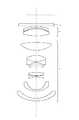
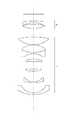
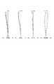
図1から7は、本発明に関する数値実施例1から7のレンズ断面を示す。図8から14は、本発明に関する数値実施例1から7の諸収差図を示す。尚諸収差図は倍率が1/27の時のそれを示す。
【0033】
図1において、Iは大きな共役側(スクリーンs)に配置された正屈折力を有しレトロフォーカス型の第1レンズ群、IIは少なくとも一枚の正の屈折力を有する正レンズと大きな共役側に強い負のパワーを持った負レンズを有する第2レンズ群である。pは、画像を形成する小さな共役としての液晶パネルのカバーガラスを示す。尚、本願のいうレトロフォーカス型とは、後側の主点がその第1レンズ群Iの最終レンズ面より小さな共役側ある事を言う。又、〜に強いパワー、あるいは〜強い屈折力を持つとは、他のレンズ面に対しての相対比較をさす。
【0034】
こうした構成のもとで、液晶に形成された画像は第1レンズ群、第2レンズ群を介したスクリーンに投影されることになる。
【0035】
第1レンズ群Iはテレセン性を良好に保つために大きな共役側に負レンズ成分を多く含み小さな共役側に正レンズ成分を多く含む構成となっている。そのため軸外光束は同じ向きのプリズム成分が多くなり、たとえば大きな共役側に第1レンズ群の上側から入射する光束は鋭角を下方にもつプリズム成分に相当するレンズ部分を通過するため非点収差や歪曲収差が多く発生してしまう。その発生する収差を補正するために第1レンズ群と小さな共役点の間に第2レンズ群を配置させ逆の収差を発生させている。第2レンズ群の大きな共役側の正レンズの大きな共役側の非球面の効果と小さな共役側の負レンズの大きな共役側のレンズ面での入射角を大きくすることにより第1レンズ群で発生する非点収差や歪曲収差を補正している。
【0036】
以下条件式の意味について説明を行う。
【0037】
条件式(1)は全系の焦点距離と第2レンズ群の焦点距離の比について限定したもので、条件式(1)の下限値を超える領域では第2レンズ群により軸外光束が大きくはね上げられ第1レンズ群の小さな共役側のレンズ径が大きくなりすぎ、条件式(1)の上限値を超える領域では第2レンズ群により軸外光束が集光されすぎて第1レンズ群の小さな共役側のレンズ面で他の像高を通る光束と軸外光束のオーバーラップ量が多くなりすぎ軸外光束の補正が困難となる。
【0038】
条件式(2)は全系の焦点距離と第2レンズ群を構成する正レンズの焦点距離の比について限定したもので条件式(2)の下限値あるいは上限値を超える領域では第2レンズ群中の正レンズのパワーが弱すぎるか強くなりすぎるため結果として条件式(1)を満足することが困難となる。
【0039】
条件式(3)は全系の焦点距離と第2レンズ群を構成する負レンズの焦点距離の比について限定したので条件式(3)の下限値あるいは上限値を超える領域では第2レンズ群の負レンズのパワーが弱すぎるか強くなりすぎるため結果として条件式(1)を満足することが困難となる。
【0040】
第2レンズ群中の正レンズ、負レンズの焦点距離が全系の焦点距離に対して条件式(2)(3)の範囲内にあれば第1レンズ群で発生する非点収差や歪曲収差と逆の収差をほぼ同量発生することができ、全系で良好な光学性能を得ることができる。
【0041】
条件式(4)は第2レンズ群中の正レンズと負レンズの空気間隔と全系の焦点距離の比について限定したもので条件式(4)の下限値を超える領域では第2レンズ群中の正レンズと負レンズの間の空気レンズで第1レンズ群で発生する収差と逆の収差を十分発生することができず、条件式(4)の上限値を超える領域では第2レンズ群中の正レンズと負レンズの間隔が大きくなりすぎ、第2レンズ群で軸外光束が大きくはね下げられるため歪曲収差がアンダーとなり好ましくない。
【0042】
条件式(5)は、第2レンズ群中の正レンズのアッベ数と負レンズのアッベ数の差について限定したもので、条件式(5)の下限値あるいは上限値を超える領域では軸外光束の光軸からこの高さが大きいところで色消しあるいは色出しが行われるため高次の倍率色収差が大きく発生するのでよくない。
【0043】
条件式(6)は第1レンズ群中の接合レンズの正レンズと負レンズのアッベ数の差について限定したもので、条件式(6)の下限値を超える領域では、軸上色収差および倍率色収差がアンダーとなり、条件式(6)の上限値を超える領域では軸上色収差および倍率色収差がオーバーとなる傾向となる。
【0044】
条件式(7)は第1レンズ群中のほぼ中央部に位置し大きな共役側に強いパワーをもつ正レンズのアッベ数とその正レンズより大きな共役側に位置する負レンズのアッベ数の平均値の差について限定したもので、条件式(7)の下限値を超える領域では軸上色収差がオーバー倍率色収差がアンダーとなり条件式(7)の上限値を超える領域では軸上色収差がアンダー、倍率色収差がオーバーとなるためよくない。
【0045】
条件式(5)、(6)、(7)は色収差補正に関する条件式で、軸外光束の光軸からの高さが低いところで倍率色収差の補正をほぼ行う構成をとるための条件式である。このような構成をとることにより高次の倍率色収差の発生を小さくすることができる。
【0046】
条件式(8),(9)は第1レンズ群中のほぼ中央部に位置し大きな共役側に強いパワーをもつ正レンズの屈折率と、小さな共役側に強いパワーをもつ正レンズの屈折率について限定したもので、条件式(8),(9)の下限値を超える領域では高次の球面収差が大きく発生する傾向となる。
【0047】
条件式(10)は第1レンズ群と第2レンズ群の空気間隔と全系の焦点距離の比について限定したもので、条件式(10)の下限値を超える領域では、第2レンズ群を通過する光束の幅が大きくなりすぎ、違う像高の光束のオーバーラップ量が多くなるため軸外収差の補正が十分行えず、条件式(10)の上限値を超える領域では第2レンズ群を通過する光束の幅が小さくなりすぎるためレンズのゴミが投影像において目立ってくる。
【0048】
条件式(11)は第1レンズ群の全長と全系の焦点距離の比について限定したもので条件式(11)の下限値を超える領域では、レンズ全長が大きくなりすぎ、条件式(11)の上限値を超える領域では第1レンズ群の全長が短くなりすぎるため第1レンズ群の大きな共役側や小さい共役側のレンズ面で違う像高の光束のオーバーラップ量が多くなりすぎるため軸外収差の補正が困難となる。
【0049】
第1レンズ群の大きな共役側に非球面を使用する場合には、非点収差および歪曲収差の補正のため負レンズに非球面を使用する場合には光軸から離れるに沿って負のパワーが弱くなる非球面を使用し、正レンズに非球面を使用する場合には光軸から離れるに沿って正のパワーが強くなる非球面を使用するのがよい。非球面はなるべく軸外光束の光軸からの高さが大きい面に使用すると違う像高の光束のオーバーラップ量が小さくなり軸外収差の補正が良好に行える。
【0050】
第2レンズ群に非球面を使用する場合には、非点収差および歪曲収差の補正のため、正レンズに非球面を使用する場合は光軸から離れるに沿い正のパワーが弱くなる非球面を使用し、負レンズに非球面を使用する場合は光軸から離れるに沿い負のパワーが弱くなる非球面を使用するのがよい。コマ収差を良好に補正するためには軸上および軸外主光線の交わる位置は第1レンズのほぼ中央に位置する2つの正レンズの間に位置するのがよい。以下に数値実施例を示す。
【0051】
尚、ri は大きな共役側から順にレンズ面の曲率半径、
di は大きな共役側から順にレンズ面間隔、
ni は大きな共役側から順にレンズのd線における屈折率、
νi は大きな共役側から順にレンズのアッベ数である。
【0052】
非球面形状は以下の式で表される。
【0053】
【外1】
K:円錐定数
Ai :i次の非球面係数である。
【0054】
条件式の値
【0055】
【表1】
【外2】
【外3】
【外4】
【外5】
【外6】
【外7】
【外8】
【発明の効果】
以上説明したように、本発明によれば、少ないレンズ構成でF.Noが1.5程度と明るく、テレセン性が良好で、周辺光量が50〜60%と豊富で光学性能が良好な単板用液晶プロジェクター用の投射レンズとして最適な大口径広角テレセントリックレンズを実現できる。
【0065】
本発明はまた投射画角が80°程度広いので特にリアプロジェクションTV用の投射レンズとして最適である。
【図面の簡単な説明】
【図1】本発明の数値実施例1のレンズ断面図。
【図2】本発明の数値実施例2のレンズ断面図。
【図3】本発明の数値実施例3のレンズ断面図。
【図4】本発明の数値実施例4のレンズ断面図。
【図5】本発明の数値実施例5のレンズ断面図。
【図6】本発明の数値実施例6のレンズ断面図。
【図7】本発明の数値実施例7のレンズ断面図。
【図8】本発明の数値実施例1の諸収差図。
【図9】本発明の数値実施例2の諸収差図。
【図10】本発明の数値実施例3の諸収差図。
【図11】本発明の数値実施例4の諸収差図。
【図12】本発明の数値実施例5の諸収差図。
【図13】本発明の数値実施例6の諸収差図。
【図14】本発明の数値実施例7の諸収差図。
【符号の説明】
I 第1レンズ群
II 第2レンズ群
SP 絞り
S サジタル像面
M メリヂオナル像面
d d線
g g線
sc 正弦条件[0001]
BACKGROUND OF THE INVENTION
The present invention relates to a projection lens used for a liquid crystal projector or the like.
[0002]
[Prior art]
Conventionally, various projection lenses for CRT have been proposed as projection lenses for enlarging and projecting original images such as liquid crystal and CRT, particularly those having a FNo of 1.5 or less. As a proposal of a projection lens for three-tube CRT projection, for example, Japanese Patent Laid-Open No. 4-31910 is cited.
[0003]
[Problems to be solved by the invention]
However, in the above-described conventional example, the projection lens for liquid crystal whose contrast is greatly changed due to a change in the incident angle of light due to poor telecentricity for correcting the curvature of field and the concave lens disposed near the image surface. Could not be applied. Further, since the peripheral light amount is as small as about 35%, there is a disadvantage that the peripheral portion of the projected image is dark.
[0004]
As described above, the conventional F.R. There was no proposal of a projection lens that could be applied to a liquid crystal projector having a bright No. of about 1.5, good telecentricity, and a large amount of peripheral light.
[0005]
The object of the present invention is to The object is to propose a projection lens suitable for the projection lens of a single-panel liquid crystal projector having a bright No. of about F1.5, excellent telecentricity and abundant amount of peripheral light.
[0006]
[Means for Solving the Problems]
Invention of the present application in order to achieve the above object, in order from the large conjugate side, havingpositive refractivepower, the first lens group retrofocushas a strong negativerefractive power on the large conjugate sideand a positive lens The second lens group is composed of a negative lens,andthe first lens group is disposed on the conjugate side smaller than the two meniscus negative lenses having a convex surface facing the large conjugate side, and smaller than the two meniscus negative lenses. A positive lens having a strong positive refractive power on the conjugate side, a positive lens having a strong positive refractive power on the large conjugate side, arranged on the small conjugate side, and joined from the large conjugate side by a negative lens and a positive lens to the large conjugate side And having at least one positive lens disposed on the conjugate side smaller than the cemented lens, and satisfying the following conditional expression .
0.1 <D12/f<1.3(10)
(More preferably 0.2 <D12/f<1.2)
0.08 <f / l1<0.35(11)
(More preferably, 0.11 <f / l1<0.27)
Where D12 isthe distance between the first lens group and the second lens group.
l1: Total length of the first lens group
Furthermore, it is desirable that the following conditional expression is satisfied.
[0009]
−0.1 <f / f2 <0.35 (1)
(More preferably 0 <f / f2 <0.3)
0.1 <f / f2p<0.5(2)
(More preferably,0.15 <f / f2p<0.45 )
−0.5 <f / f2n<−0.02(3)
(More preferably-0.45 <f / f 2n <-0.05 )
Where f: focal length of the entire system.
f2: Focal length of the second lens group
f2p: Focal length of the positive lens in the second lens group
f2n: focal length of the negative lens of the second lens group
Furthermore, it is desirable that the following conditional expression is satisfied.
[0015]
0.05 <dm2 /f<0.35 (4)
(More preferably 0.1 <dm2 / f <0.3)
Where dm2 isthe distance between thepositive lens and the negative lens in the second lens group.
Furthermore, it is desirable that the following conditional expression is satisfied.
[0019]
−20 <ν2p−ν2n<20(5)
(More preferably, −15 <ν2p−ν2n<15)
20 <ν1hp −ν1hn <45 (6)
(More preferably 25 <ν1hp −ν1hn <40)
20 <ν1fn −ν1mfp <50 (7)
(More preferably, 25 <ν1fn −ν1mfp <45)
Whereν2p: Abbe number of the positive lens in the second lens group
ν2n: Abbe number of the negative lens in the second lens group ν1hp : Abbe number ofthe positive lensconstituting the cemented lensin the first lens group
ν1hn: Abbe number of the negative lens constituting the cemented lens in the first lens group
ν1fn: Average value of the Abbe number of the negative lens located on the conjugate side larger than the positive lens having strong refractive power on the large conjugate side in the first lens group
ν1mfp: Abbe number of a positive lens having strong refractive power on the large conjugate side in the first lens group
Furthermore, the aspherical surface in the first lens group is located on the large conjugate side in the first lens group, and when an aspherical surface is used for the negative lens, the aspherical surface in which the negative power becomes weaker as the distance from the optical axis increases. When an aspherical surface is used for the positive lens, it is desirable that the aspherical surface has a positive power that increases with distance from the optical axis.
[0026]
Further, the aspherical surface in the second lens group is an aspherical surface where the positive power is weakened away from the optical axis when an aspherical surface is used for the positive lens, and an aspherical surface is used for the negative lens. Is preferably an aspheric surface in which the negative power increases along the distance from the optical axis.
[0031]
Furthermore, the point where the axial principal ray and the off-axis principal ray intersect isthat a positive lens having a strong positive refractive power on the large conjugate side in the first lens groupand a positive lens having a strong positive refractive power on the large conjugate side. It is desirable to be located betweena positive lenshaving a smaller conjugate side and a larger conjugate side than the cemented lens and having a strong refractive power on the small conjugate side .
Furthermore, it is desirable that the following conditional expression is satisfied.
n1mfp> 1.7
(More preferably, n1mfp> 1.75)
n1mrp> 1.7
(More preferably, n1mrp> 1.75)
Where n1mfpis the refractive index of a positive lens having a strong positive refractive power on the large conjugate side in the first lens group.
n1mrp: a positive side having a strong refractive power on the small conjugate side which is smaller than the positive lens having a strong positive refractive power on the large conjugate side in the first lens group and is located on the large conjugate side than the cemented lens. Refractive index of lens [0032]
DETAILED DESCRIPTION OF THE INVENTION
〔Example〕
1 to7 show lens cross sections of Numerical Examples 1 to7 according to the present invention.8 to14 show various aberration diagrams of Numerical Examples 1 to7 relating to the present invention. The various aberration diagrams show that when the magnification is 1/27.
[0033]
In FIG. 1, I is a first retrofocus type lens group having positive refracting power arranged on the large conjugate side (screen s), and II is at least one positive lens having positive refracting power and the large conjugate side. This is a second lens group having a negative lens having a strong negative power. p denotes a cover glass of a liquid crystal panel as a small conjugate for forming an image. The term “retrofocus type” as used in the present application means that the principal point on the rear side is on a conjugate side smaller than the final lens surface of the first lens group I. In addition, to have a strong power or a strong refractive power means a relative comparison with respect to other lens surfaces.
[0034]
Under such a configuration, the image formed on the liquid crystal is projected onto the screen via the first lens group and the second lens group.
[0035]
The first lens unit I is configured to include a large amount of negative lens components on the large conjugate side and a large amount of positive lens components on the small conjugate side in order to maintain good telecentricity. For this reason, the off-axis light beam has many prism components in the same direction. For example, the light beam incident on the large conjugate side from the upper side of the first lens group passes through the lens portion corresponding to the prism component having the acute angle below, so that astigmatism or Many distortions occur. In order to correct the generated aberration,the second lens group is disposed between the first lens group and a small conjugate point to generate the opposite aberration. This occurs in the first lens group by increasing the incident angle of the large conjugate side aspherical surface of the large conjugate side positive lens of the second lens group and the large conjugate side lens surface of the small conjugate side negative lens. Astigmatism and distortion are corrected.
[0036]
The meaning of the conditional expression will be described below.
[0037]
Conditional expression (1) limits the ratio between the focal length of the entire system and the focal length of the second lens group. In the region exceeding the lower limit value of conditional expression (1), the off-axis light beam is greatly raised by the second lens group. In the region where the lens diameter on the small conjugate side of the first lens group becomes too large and the upper limit value of the conditional expression (1) is exceeded, the off-axis light beam is too condensed by the second lens group and the small conjugate of the first lens group. On the lens surface on the side, the amount of overlap between the light beam passing through another image height and the off-axis light beam becomes too large, and it becomes difficult to correct the off-axis light beam.
[0038]
Conditional expression (2) limits the ratiobetween thefocal length of the entire system and the focal length of thepositive lens constituting the second lens group, and in the region exceeding the lower limit value or upper limit value of conditional expression (2), the second lens group. Since the power of thepositive lens inside is too weak or too strong, it is difficult to satisfy the conditional expression (1) as a result.
[0039]
Conditional expression (3) limits the ratio between the focal length of the entire system and the focal length of thenegative lens that constitutes the second lens group. Therefore, in the region exceeding the lower limit value or the upper limit value of conditional expression (3),Since the power of thenegative lens is too weak or too strong, it is difficult to satisfy the conditional expression (1) as a result.
[0040]
Astigmatism and distortion occurring in the first lens group if the focal lengthsof the positive lens and negative lens in the second lens group arewithin the range of conditional expressions (2) and (3) with respect to the focal length of the entire system. As a result, almost the same amount of aberration can be generated, and good optical performance can be obtained in the entire system.
[0041]
Conditional expression (4) limits the ratio of the air distance betweenthe positive lens and negative lens in the second lens group and the focal length of the entire system, and in the region exceeding the lower limit of conditional expression (4), The air lens betweenthe positive lens and the negative lens cannot sufficiently generate aberration opposite to the aberration generated in the first lens group, and in the region exceeding the upper limit of the conditional expression (4), The distance between the positive lens and the negative lens becomes too large, and the off-axis luminous flux is greatly repelled by the second lens group, which is unfavorable because distortion becomes under.
[0042]
Conditional expression (5) limits the difference between the Abbe number of thepositive lens and the negative lens in the second lens group, andin the region exceeding the lower limit value or upper limit value of conditional expression (5), the off-axis light beam Since achromaticity or coloration is performed at a position where this height is large from the optical axis, high-order lateral chromatic aberration is greatly generated, which is not good.
[0043]
Conditional expression (6) limits the difference between the Abbe numbers of the positive lens and negative lens of the cemented lens in the first lens group. In the region exceeding the lower limit of conditional expression (6), axial chromatic aberration and lateral chromatic aberration are obtained. Becomes under and the axial chromatic aberration and the lateral chromatic aberration tend to be over in a region exceeding the upper limit value of the conditional expression (6).
[0044]
Conditional expression (7) is an average value of the Abbe number of a positive lens having a strong power on the large conjugate side located substantially in the center of the first lens group and the Abbe number of a negative lens located on the conjugate side larger than the positive lens. In the region where the lower limit value of conditional expression (7) is exceeded, the axial chromatic aberration is under-extensive chromatic aberration, and in the region exceeding the upper limit value of conditional expression (7), the axial chromatic aberration is under, and the chromatic aberration of magnification. Is not good because it becomes over.
[0045]
Conditional expressions (5), (6), and (7) are conditional expressions relating to chromatic aberration correction, and are conditional expressions for substantially correcting magnification chromatic aberration when the height of the off-axis light beam from the optical axis is low. . By taking such a configuration, it is possible to reduce the occurrence of high-order lateral chromatic aberration.
[0046]
Conditional expressions (8) and (9) are the refractive index of the positive lens having a strong power on the large conjugate side and the positive lens having a strong power on the small conjugate side, which is located almost in the center of the first lens group. In the region exceeding the lower limit of conditional expressions (8) and (9), high-order spherical aberration tends to occur greatly.
[0047]
Conditional expression (10) limits the ratio of the air gap between the first lens group and the second lens group and the focal length of the entire system. In the region exceeding the lower limit of conditional expression (10), the second lens group is The width of the light beam passing through becomes too large, and the amount of overlap of the light beams having different image heights increases, so that the off-axis aberration cannot be sufficiently corrected. In the region exceeding the upper limit value of the conditional expression (10), the second lens group is set. Since the width of the light beam passing through becomes too small, lens dust becomes conspicuous in the projected image.
[0048]
Conditional expression (11) limits the ratio between the total length of the first lens unit and the focal length of the entire system. In the region exceeding the lower limit of conditional expression (11), the total lens length becomes too large, and conditional expression (11) In the region exceeding the upper limit of the first lens group, the total length of the first lens group becomes too short, so that the amount of overlap of light beams with different image heights on the large conjugate side and small conjugate side lens surfaces of the first lens group becomes too large. It becomes difficult to correct aberrations.
[0049]
When an aspheric surface is used on the large conjugate side of the first lens group, a negative power is generated along the distance from the optical axis when an aspheric surface is used for a negative lens to correct astigmatism and distortion. When an aspheric surface that weakens is used and an aspheric surface is used for the positive lens, it is preferable to use an aspheric surface that has a positive power that increases with distance from the optical axis. If an aspherical surface is used on a surface where the height of the off-axis light beam from the optical axis is as large as possible, the amount of overlap of the light beam with a different image height is reduced, and the off-axis aberration can be corrected satisfactorily.
[0050]
When using an aspherical surface for the second lens group, to correct astigmatism and distortion, when using an aspherical surface for the positive lens, an aspherical surface whose positive power decreases along the distance from the optical axis. When using an aspherical surface for the negative lens, it is preferable to use an aspherical surface in which the negative power becomes weaker away from the optical axis. In order to satisfactorily correct coma, the position where the on-axis and off-axis chief rays intersect is preferably located between two positive lenses located approximately at the center of the first lens. Numerical examples are shown below.
[0051]
Ri is the radius of curvature of the lens surface in order from the large conjugate side,
di is the distance between the lens surfaces in order from the large conjugate side,
ni is the refractive index at the d-line of the lens in order from the large conjugate side,
νi is the Abbe number of the lens in order from the large conjugate side.
[0052]
The aspheric shape is expressed by the following formula.
[0053]
[Outside 1]
[0054]
Conditional expression value [0055]
[Table 1]
[Outside 2]
[Outside 3]
[Outside 4]
[Outside 5]
[Outside 6]
[Outside 7]
[Outside 8]
【The invention's effect】
As described above, according to the present invention, the F.F. A large aperture wide-angle telecentric lens that is optimal as a projection lens for a single-plate liquid crystal projector that has a bright No. of about 1.5, good telecentricity, abundant peripheral light amount of 50-60%, and good optical performance. .
[0065]
The present invention is particularly suitable as a projection lens for a rear projection TV because the projection angle of view is as wide as about 80 °.
[Brief description of the drawings]
FIG. 1 is a lens cross-sectional view of Numerical Example 1 of the present invention.
FIG. 2 is a lens cross-sectional view of Numerical Example 2 of the present invention.
FIG. 3 is a lens cross-sectional view of Numerical Example 3 according to the present invention.
FIG. 4 is a lens sectional view of Numerical Example 4 of the present invention.
FIG. 5 is a lens sectional view of Numerical Example 5 of the present invention.
FIG. 6 is a lens cross-sectional view of Numerical Example 6 according to the present invention.
FIG. 7 is a lens cross-sectional view of Numerical Example 7 of the present invention.
FIG.8 is a diagram showing various aberrations of Numerical Example 1 of the present invention.
FIG.9 is a diagram showing various aberrations of Numerical Example 2 according to the present invention.
FIG.10 is a diagram showing various aberrations of Numerical Example 3 according to the present invention.
FIG.11 is a diagram showing various aberrations of Numerical Example 4 of the present invention.
FIG.12 is a diagram showing various aberrations of Numerical Example 5 according to the present invention.
FIG.13 is a diagram illustrating all aberrations of Numerical Example 6 according to the present invention.
FIG.14 is a diagram showing various aberrations of Numerical Example 7 according to the present invention.
[Explanation of symbols]
I First lens group II Second lens group SP Aperture S Sagittal image plane M Meridional image plane dd line g g line sc Sine condition
Claims (10)
Translated fromJapanese0.1<D12/f<1.3
0.08<f/l1<0.35
ここでD12:前記第1レンズ群と前記第2レンズ群の間隔
l1:前記第1レンズ群の全長In order from the large conjugate side, havingpositive refractivepower, the first lens group retrofocus is constituted by the second lens groupcomprising a negative lenshaving apositive lens and a strong negativerefractive power on the large conjugate side,The first lens group includes two meniscus negative lenses having a convex surface facing the large conjugate side, a positive lens disposed on the conjugate side smaller than the two meniscus negative lenses and having a strong positive refractive power on the large conjugate side. A cemented lens having a cemented surface arranged on the smaller conjugate side than the positive lens having a strong positive refractive power on the large conjugate side and cemented by a negative lens and a positive lens from the large conjugate side and having a convex surface facing the large conjugate side A large-aperture wide-angle telecentric lenshaving at least one positive lens disposed on the conjugate side smaller than the cemented lens and satisfying the following conditional expression:
0.1 <D12/f<1.3
0.08 <f / l1<0.35
Where D12 isan interval between the first lens group and the second lens group.
l1: full length of the first lens group
−0.1<f/f2<0.35
0.1<f/f2p<0.5
−0.5<f/f2n<−0.02
ここでf:全系の焦点距離。
f2:前記第2レンズ群の焦点距離
f2p:前記第2レンズ群の正レンズの焦点距離
f2n:前記第2レンズ群の負レンズの焦点距離The large-aperture wide-angle telecentric lens according toclaim 1 , wherein the following conditional expression is satisfied.
−0.1 <f / f2 <0.35
0.1 <f / f2p<0.5
−0.5 <f / f2n<−0.02
Where f: focal length of the entire system.
f2 : focal length of the second lens group
f2p: focal length of the positive lens of the second lens group
f2n: focal length of the negative lens of the second lens group
0.05<dm2/f<0.35
ここでdm2:第2レンズ群の正レンズと負レンズの間隔
f:全系の焦点距離。The large-aperture wide-angle telecentric lens according toclaim 1 or 2 , wherein the following conditional expression is satisfied.
0.05<d m2 /f<0.35
Where dm2 isthe distance between thepositive lens and the negative lens in the second lens group,and f is the focal length of the entire system.
−20<ν2p−ν2n<20
20<ν1hp−ν1hn<45
20<ν1fn−ν1mfp<50
ここでν2p:前記第2レンズ群の正レンズのアッベ数
ν2n:前記第2レンズ群の負レンズのアッベ数
ν1hp:前記第1レンズ群中の前記接合レンズを構成する正レンズのアッベ数
ν1hn:前記第1レンズ群中の前記接合レンズを構成する負レンズのアッベ数
ν1fn:前記第1レンズ群中の前記大きな共役側に強い屈折力を有する正レンズより大きな共役側に位置する負レンズのアッベ数の平均値
ν1mfp:前記第1レンズ群中の前記大きな共役側に強い屈折力を有する正レンズのアッベ数The large-aperture wide-angle telecentric lens accordingto any one ofclaims 1 to 3, wherein the following conditional expression is satisfied.
−20 <ν2p −ν2n <20
20 <ν1hp −ν1hn <45
20 <ν1fn −ν1mfp <50
Here [nu2p: the Abbe number of thepositive lens in the second lens group [nu2n: the Abbe number of thenegative lens in the second lens group [nu1 hp: Abbe positive lensconstitutingthe cemented lens in the first lens group number [nu1hn: the first Abbe number of the negative lensconstitutingthe cemented lens of the lens in the groupν 1fn: located on the large conjugate side than the positive lenshaving a strongrefractive power tothe large conjugate side in said first lens group a negative lens of an average Abbe number of [nu1Mfp to: Abbe number of the positive lenshaving a strongrefractive power tothe large conjugate side in said first lens group
n1mfp>1.7
n1mrp>1.7
ここでn1mfp:前記第1レンズ群中の前記大きな共役側に強い正の屈折力を有する正レンズの屈折率
n1mrp:前記第1レンズ群中の前記大きな共役側に強い正の屈折力を有する正レンズより小さな共役側であって、前記接合レンズより大きな共役側に配置された小さな共役側に強い屈折力を有する正レンズの屈折率The large-aperture wide-angle telecentric lens according toclaim 9 , wherein the following conditional expression is satisfied.
n1mfp > 1.7
n1mrp > 1.7
Where n1mfp :refractive index of a positive lens having a strong positive refractive power on the large conjugate side inthe first lens group n1mrp : astrong positive refractive power on the large conjugate side in the first lens group Refractive index of a positive lenshaving a strong refracting power on a small conjugate side that is smaller than a positive lens having a conjugate side and larger than the cemented lens
Priority Applications (5)
| Application Number | Priority Date | Filing Date | Title |
|---|---|---|---|
| JP20206296AJP3610166B2 (en) | 1996-07-31 | 1996-07-31 | Large aperture wide angle telecentric lens |
| US08/900,131US5920433A (en) | 1996-07-31 | 1997-07-25 | Large relative aperture telecentric lens |
| DE69739112TDE69739112D1 (en) | 1996-07-31 | 1997-07-29 | Telecentric high aperture lens |
| EP97113007AEP0822433B1 (en) | 1996-07-31 | 1997-07-29 | Large relative aperture telecentric lens |
| KR1019970036115AKR100299391B1 (en) | 1996-07-31 | 1997-07-30 | Teletrick lens system |
Applications Claiming Priority (1)
| Application Number | Priority Date | Filing Date | Title |
|---|---|---|---|
| JP20206296AJP3610166B2 (en) | 1996-07-31 | 1996-07-31 | Large aperture wide angle telecentric lens |
Publications (2)
| Publication Number | Publication Date |
|---|---|
| JPH1048513A JPH1048513A (en) | 1998-02-20 |
| JP3610166B2true JP3610166B2 (en) | 2005-01-12 |
Family
ID=16451320
Family Applications (1)
| Application Number | Title | Priority Date | Filing Date |
|---|---|---|---|
| JP20206296AExpired - Fee RelatedJP3610166B2 (en) | 1996-07-31 | 1996-07-31 | Large aperture wide angle telecentric lens |
Country Status (5)
| Country | Link |
|---|---|
| US (1) | US5920433A (en) |
| EP (1) | EP0822433B1 (en) |
| JP (1) | JP3610166B2 (en) |
| KR (1) | KR100299391B1 (en) |
| DE (1) | DE69739112D1 (en) |
Families Citing this family (14)
| Publication number | Priority date | Publication date | Assignee | Title |
|---|---|---|---|---|
| US6285509B1 (en) | 1997-12-25 | 2001-09-04 | Canon Kabushiki Kaisha | Zoom lens and display apparatus having the same |
| JP2001045521A (en) | 1999-07-30 | 2001-02-16 | Canon Inc | Stereoscopic image photographing optical system and stereoscopic image photographing apparatus using the same |
| JP2001124991A (en) | 1999-10-28 | 2001-05-11 | Canon Inc | Optical system for stereoscopic photography and stereoscopic imaging apparatus using the same |
| US6476983B2 (en) | 1999-12-07 | 2002-11-05 | Canon Kabushiki Kaisha | Eyepiece lens, objective lens, and optical apparatus having them |
| JP2001166258A (en)* | 1999-12-10 | 2001-06-22 | Canon Inc | Optical system for stereoscopic image photographing and stereoscopic image photographing apparatus using the same |
| JP2001218230A (en) | 2000-02-02 | 2001-08-10 | Canon Inc | Stereoscopic imaging device |
| KR100406610B1 (en)* | 2001-04-30 | 2003-11-20 | 삼성테크윈 주식회사 | Wide-angle projection lens |
| CN100380161C (en) | 2004-03-10 | 2008-04-09 | 佳能株式会社 | Zoom lens and image display apparatus including the zoom lens |
| TWI427352B (en) | 2010-09-30 | 2014-02-21 | Young Optics Inc | Fixed-focus lens |
| JP6189736B2 (en) | 2013-12-18 | 2017-08-30 | 富士フイルム株式会社 | Imaging lens and imaging apparatus |
| JP6320904B2 (en)* | 2014-11-25 | 2018-05-09 | 富士フイルム株式会社 | Imaging lens and imaging apparatus |
| KR101976278B1 (en)* | 2017-11-09 | 2019-05-07 | 경북대학교 산학협력단 | Super multiview tabletop display device |
| JP2020052350A (en)* | 2018-09-28 | 2020-04-02 | 富士フイルム株式会社 | Imaging lens and imaging device |
| CN115407494A (en)* | 2022-09-02 | 2022-11-29 | 天活松林光学(广州)有限公司 | A large-aperture object-space telecentric lens |
Family Cites Families (16)
| Publication number | Priority date | Publication date | Assignee | Title |
|---|---|---|---|---|
| JPS5336326B2 (en)* | 1972-12-26 | 1978-10-02 | ||
| JPH0617938B2 (en)* | 1982-08-16 | 1994-03-09 | オリンパス光学工業株式会社 | Zoom lens |
| GB2153543B (en)* | 1983-12-28 | 1988-09-01 | Canon Kk | A projection exposure apparatus |
| US4986642A (en)* | 1987-11-20 | 1991-01-22 | Olympus Optical Co., Ltd. | Objective lens system for endoscopes and image pickup system equipped with said objective lens system |
| US5005957A (en)* | 1988-09-07 | 1991-04-09 | Olympus Optical Co., Ltd. | Objective lens system for endoscopes |
| JP2596810B2 (en)* | 1988-09-12 | 1997-04-02 | オリンパス光学工業株式会社 | Optical system for endoscope |
| JP2548359B2 (en)* | 1989-03-01 | 1996-10-30 | 松下電器産業株式会社 | Projection lens and projection TV using it |
| US5303087A (en)* | 1990-11-08 | 1994-04-12 | Canon Kabushiki Kaisha | Retrofocus type lens |
| JP3040187B2 (en)* | 1991-04-11 | 2000-05-08 | パイオニア株式会社 | Projection lens |
| JP2887004B2 (en)* | 1991-04-26 | 1999-04-26 | キヤノン株式会社 | Projection optical system and optical apparatus having the same |
| JP3008580B2 (en)* | 1991-07-12 | 2000-02-14 | キヤノン株式会社 | Zoom lens |
| JP3021127B2 (en)* | 1991-10-23 | 2000-03-15 | キヤノン株式会社 | Retro focus lens |
| US5390048A (en)* | 1991-12-02 | 1995-02-14 | Matsushita Electric Industrial Co., Ltd. | Projection lens assembly and projection display apparatus |
| JP3175411B2 (en)* | 1993-06-25 | 2001-06-11 | キヤノン株式会社 | Zoom lens |
| US5600490A (en)* | 1993-10-06 | 1997-02-04 | Canon Kabushiki Kaisha | Zoom lens for projecting video image |
| JP3466002B2 (en)* | 1995-07-13 | 2003-11-10 | 三菱電機株式会社 | Retro focus lens |
- 1996
- 1996-07-31JPJP20206296Apatent/JP3610166B2/ennot_activeExpired - Fee Related
- 1997
- 1997-07-25USUS08/900,131patent/US5920433A/ennot_activeExpired - Lifetime
- 1997-07-29DEDE69739112Tpatent/DE69739112D1/ennot_activeExpired - Lifetime
- 1997-07-29EPEP97113007Apatent/EP0822433B1/ennot_activeExpired - Lifetime
- 1997-07-30KRKR1019970036115Apatent/KR100299391B1/ennot_activeExpired - Fee Related
Also Published As
| Publication number | Publication date |
|---|---|
| US5920433A (en) | 1999-07-06 |
| JPH1048513A (en) | 1998-02-20 |
| DE69739112D1 (en) | 2009-01-02 |
| EP0822433A3 (en) | 1998-10-28 |
| KR100299391B1 (en) | 2002-04-24 |
| EP0822433A2 (en) | 1998-02-04 |
| EP0822433B1 (en) | 2008-11-19 |
| KR980010589A (en) | 1998-04-30 |
Similar Documents
| Publication | Publication Date | Title |
|---|---|---|
| JP4232269B2 (en) | Projection optical system | |
| JP2924117B2 (en) | Zoom lens | |
| JP2002031754A (en) | Projection lens device and projection type image display device | |
| JP3610166B2 (en) | Large aperture wide angle telecentric lens | |
| JP2019035873A (en) | Projection optical system and projection display device | |
| JPH05113534A (en) | Retrofocus type lens | |
| JP2740662B2 (en) | Objective lens for endoscope | |
| JP2992547B2 (en) | Super wide angle lens | |
| JP2578481B2 (en) | Projection lens | |
| JP2000028919A (en) | Medium telephoto lens | |
| JP4689147B2 (en) | Projection zoom lens and enlargement projection device | |
| JP4240342B2 (en) | Retro focus lens | |
| JP3397447B2 (en) | Large aperture super wide angle lens system | |
| JPH07168095A (en) | Triplet lens | |
| JP3430738B2 (en) | Symmetric telecentric optics | |
| JPH05203871A (en) | Retrofocus type lens | |
| JPH11271610A (en) | Medium telephoto lens | |
| JP3033148B2 (en) | Compact zoom lens | |
| JP2002131636A (en) | Projecting lens | |
| JP4453120B2 (en) | Zoom lens | |
| JP2813744B2 (en) | Projection lens | |
| JP2800293B2 (en) | Projection lens | |
| JP2004177688A (en) | Projection lens and liquid crystal projector | |
| JP3118030B2 (en) | Ultra wide-angle lens with compact rear focus | |
| JPH0455807A (en) | Objective lens of endoscope |
Legal Events
| Date | Code | Title | Description |
|---|---|---|---|
| A977 | Report on retrieval | Free format text:JAPANESE INTERMEDIATE CODE: A971007 Effective date:20040407 | |
| A131 | Notification of reasons for refusal | Free format text:JAPANESE INTERMEDIATE CODE: A131 Effective date:20040420 | |
| A521 | Request for written amendment filed | Free format text:JAPANESE INTERMEDIATE CODE: A523 Effective date:20040616 | |
| A131 | Notification of reasons for refusal | Free format text:JAPANESE INTERMEDIATE CODE: A131 Effective date:20040713 | |
| A521 | Request for written amendment filed | Free format text:JAPANESE INTERMEDIATE CODE: A523 Effective date:20040910 | |
| TRDD | Decision of grant or rejection written | ||
| A01 | Written decision to grant a patent or to grant a registration (utility model) | Free format text:JAPANESE INTERMEDIATE CODE: A01 Effective date:20041012 | |
| A61 | First payment of annual fees (during grant procedure) | Free format text:JAPANESE INTERMEDIATE CODE: A61 Effective date:20041018 | |
| R150 | Certificate of patent or registration of utility model | Free format text:JAPANESE INTERMEDIATE CODE: R150 | |
| FPAY | Renewal fee payment (event date is renewal date of database) | Free format text:PAYMENT UNTIL: 20071022 Year of fee payment:3 | |
| FPAY | Renewal fee payment (event date is renewal date of database) | Free format text:PAYMENT UNTIL: 20081022 Year of fee payment:4 | |
| FPAY | Renewal fee payment (event date is renewal date of database) | Free format text:PAYMENT UNTIL: 20091022 Year of fee payment:5 | |
| FPAY | Renewal fee payment (event date is renewal date of database) | Free format text:PAYMENT UNTIL: 20091022 Year of fee payment:5 | |
| FPAY | Renewal fee payment (event date is renewal date of database) | Free format text:PAYMENT UNTIL: 20101022 Year of fee payment:6 | |
| FPAY | Renewal fee payment (event date is renewal date of database) | Free format text:PAYMENT UNTIL: 20101022 Year of fee payment:6 | |
| FPAY | Renewal fee payment (event date is renewal date of database) | Free format text:PAYMENT UNTIL: 20111022 Year of fee payment:7 | |
| FPAY | Renewal fee payment (event date is renewal date of database) | Free format text:PAYMENT UNTIL: 20111022 Year of fee payment:7 | |
| FPAY | Renewal fee payment (event date is renewal date of database) | Free format text:PAYMENT UNTIL: 20121022 Year of fee payment:8 | |
| FPAY | Renewal fee payment (event date is renewal date of database) | Free format text:PAYMENT UNTIL: 20131022 Year of fee payment:9 | |
| LAPS | Cancellation because of no payment of annual fees |