JP3609832B2 - Device for supporting breast shield and associated breast pump - Google Patents
Device for supporting breast shield and associated breast pumpDownload PDFInfo
- Publication number
- JP3609832B2 JP3609832B2JP52242896AJP52242896AJP3609832B2JP 3609832 B2JP3609832 B2JP 3609832B2JP 52242896 AJP52242896 AJP 52242896AJP 52242896 AJP52242896 AJP 52242896AJP 3609832 B2JP3609832 B2JP 3609832B2
- Authority
- JP
- Japan
- Prior art keywords
- breast
- shield
- breast shield
- band
- pump
- Prior art date
- Legal status (The legal status is an assumption and is not a legal conclusion. Google has not performed a legal analysis and makes no representation as to the accuracy of the status listed.)
- Expired - Fee Related
Links
- 210000000481breastAnatomy0.000titleclaimsdescription425
- 239000000463materialSubstances0.000claimsdescription15
- 210000004251human milkAnatomy0.000claimsdescription12
- 235000020256human milkNutrition0.000claimsdescription12
- 230000002093peripheral effectEffects0.000claimsdescription4
- 210000002445nippleAnatomy0.000claimsdescription3
- 239000008267milkSubstances0.000description11
- 210000004080milkAnatomy0.000description11
- 235000013336milkNutrition0.000description10
- 239000004744fabricSubstances0.000description7
- 210000002414legAnatomy0.000description7
- 230000004048modificationEffects0.000description6
- 238000012986modificationMethods0.000description6
- 230000007246mechanismEffects0.000description5
- 210000003127kneeAnatomy0.000description4
- 238000000034methodMethods0.000description4
- 230000009471actionEffects0.000description3
- 238000010586diagramMethods0.000description3
- 239000013013elastic materialSubstances0.000description3
- 238000003780insertionMethods0.000description3
- 230000037431insertionEffects0.000description3
- 239000007788liquidSubstances0.000description3
- 230000001580bacterial effectEffects0.000description2
- 238000009434installationMethods0.000description2
- 230000000474nursing effectEffects0.000description2
- 241000894006BacteriaSpecies0.000description1
- 239000004606Fillers/ExtendersSubstances0.000description1
- 239000002390adhesive tapeSubstances0.000description1
- 239000011324beadSubstances0.000description1
- 238000004140cleaningMethods0.000description1
- 230000008878couplingEffects0.000description1
- 238000010168coupling processMethods0.000description1
- 238000005859coupling reactionMethods0.000description1
- 239000004033plasticSubstances0.000description1
- 238000005086pumpingMethods0.000description1
- 230000008439repair processEffects0.000description1
- 238000009958sewingMethods0.000description1
- 210000001562sternumAnatomy0.000description1
Images


Classifications
- A—HUMAN NECESSITIES
- A61—MEDICAL OR VETERINARY SCIENCE; HYGIENE
- A61M—DEVICES FOR INTRODUCING MEDIA INTO, OR ONTO, THE BODY; DEVICES FOR TRANSDUCING BODY MEDIA OR FOR TAKING MEDIA FROM THE BODY; DEVICES FOR PRODUCING OR ENDING SLEEP OR STUPOR
- A61M1/00—Suction or pumping devices for medical purposes; Devices for carrying-off, for treatment of, or for carrying-over, body-liquids; Drainage systems
- A61M1/06—Milking pumps
- A61M1/062—Pump accessories
- A61M1/064—Suction cups
- A—HUMAN NECESSITIES
- A41—WEARING APPAREL
- A41C—CORSETS; BRASSIERES
- A41C3/00—Brassieres
- A41C3/04—Brassieres for nursing mothers
- A—HUMAN NECESSITIES
- A61—MEDICAL OR VETERINARY SCIENCE; HYGIENE
- A61M—DEVICES FOR INTRODUCING MEDIA INTO, OR ONTO, THE BODY; DEVICES FOR TRANSDUCING BODY MEDIA OR FOR TAKING MEDIA FROM THE BODY; DEVICES FOR PRODUCING OR ENDING SLEEP OR STUPOR
- A61M1/00—Suction or pumping devices for medical purposes; Devices for carrying-off, for treatment of, or for carrying-over, body-liquids; Drainage systems
- A61M1/06—Milking pumps
- A61M1/062—Pump accessories
- A61M1/067—Pump accessories with means for hands-free operation
- A—HUMAN NECESSITIES
- A61—MEDICAL OR VETERINARY SCIENCE; HYGIENE
- A61M—DEVICES FOR INTRODUCING MEDIA INTO, OR ONTO, THE BODY; DEVICES FOR TRANSDUCING BODY MEDIA OR FOR TAKING MEDIA FROM THE BODY; DEVICES FOR PRODUCING OR ENDING SLEEP OR STUPOR
- A61M2209/00—Ancillary equipment
- A61M2209/08—Supports for equipment
- A61M2209/088—Supports for equipment on the body
Landscapes
- Health & Medical Sciences (AREA)
- Heart & Thoracic Surgery (AREA)
- Engineering & Computer Science (AREA)
- General Health & Medical Sciences (AREA)
- Life Sciences & Earth Sciences (AREA)
- Anesthesiology (AREA)
- Biomedical Technology (AREA)
- Hematology (AREA)
- Vascular Medicine (AREA)
- Animal Behavior & Ethology (AREA)
- Pediatric Medicine (AREA)
- Public Health (AREA)
- Veterinary Medicine (AREA)
- Nursing (AREA)
- Textile Engineering (AREA)
- Corsets Or Brassieres (AREA)
- External Artificial Organs (AREA)
Description
Translated fromJapanese発明の背景
本発明は一般的には搾乳器に関し、特に、乳房シールド並びに関連した搾乳器を婦人の乳房で支持するための装置に関する。
後の使用のために母乳を搾り出して保存するための搾乳器が良く知られている。一般的には、2種類の搾乳器、即ちモータ駆動式搾乳器及び手動式搾乳器が養母による使用のために入手できる。典型的には、これらの搾乳器は、乳首に嵌まる漏斗形シールド即ちフードと、乳房シールド内に間欠的な真空を発生させるための、乳房シールドに接続されたある種の真空ポンプ(例えば、手動式ピストンシリンダ、絞り球(バルブ)、又は電動式真空装置)と、搾り出した母乳用の容器と、を有する。乳房シールド内に真空ポンプによって発生させた間欠的吸引により、乳房を引っ張ったりは押したりして、幼児の吸乳作用そっくりにまね、それによって乳房から乳を搾りだす。搾り出した乳は典型的には、保存及びその後の幼児による使用のために、乳房シールドから収集容器に流れる。小さい乳ボトルのような収集容器は普通は、例えば中間乳差し向けチャンネル及び弁装置を介して乳房シールドに組み込まれる。
養母用に特に設計されたブラジャー、ホルダートップ、及び他の被服も良く知られている。一般的には、これらの哺乳用ブラジャーは、幼児による哺乳のために、或いはポンプによる母乳収集を可能にするために、乳房を露出させるべく一方の側でブラジャーから外せるフラップを有する。
哺乳用ブラジャー又はそうでないものを着けたまま、搾乳器を使用して母乳を集め且つ保存したいときには、乳房を露出させた後、母が乳房シールドを露出させた乳房の適所に保持する。明らかに、搾乳器がモータ駆動されるか手で操作されるかに応じて、更に、1つ又は2つの乳房シールドが同時に使用されているかに応じて、搾乳操作を行うのに母の片方の手又は両方の手を必要とする。容易に分かるように、自宅にいるか仕事場にいるかで、養母は、搾乳器を使用しているとき、他の仕事を行うために、少なくとも片方の手が使えない。従って、母が他の仕事を行うために手を自由に使えるようにしながら搾乳器を使用できるようにする方法及び装置を開発する事が有利である。
発明の概要
本発明の主たる目的は、使用者が手を使わないで搾乳器の乳房シールドを露出させた乳房で支持する装置を提供することにある。関連した方法も提供する。以下に開示するように、本発明はその最も広い意味では、乳房シールドを適所に保持するのに使用者或いは他の誰かを必要とすることなく、乳房シールドを乳房の適所に保持する非動物手段を提供する。乳房シールド支持体は母の身体で、又はシールドを据えつけるように移動できるベースで支持され、母は乳房を挿入することができる。・・・・・・
本発明の1つの観点では、かかる支持方法及び装置はベースとして役立つブラジャー又は他の同様な衣服と、ベースと関連した露出で乳房で乳房シールドを支持するための手段とを提供する。
1つの実施形態では、支持手段はブラジャー及び乳房シールドに相互係合ファスナーエレメントを有する解放可能なファスナー機構の形態をとる。ブラジャーは、搾乳器の乳房シールドの据え付けのために乳房を露出させる穴を、フラップによって作られるようなカップに有する。ブラジャー及び乳房シールドの対応するファスナーエレメントを互いに留めて乳房シールドを露出した乳房で支持する。
種々の留め機構を採用することができる。例えば、乳房シールドの取り外し自在に取付けたハーネスは例えばホック、ボタン、スナップ等によってブラジャー/ベースに解放可能に留められる帯を有する。他の実施形態では、留め機構の部品には乳房シールドが一体に形成される。
本発明の他の実施形態によれば、支持手段は特に乳房シールドを適所に保持するようになったブラジャー型被服に見られるフラップ及びフラップ開口の形態を取る。例えば、フラップに設けられた開口は少なくとも1つの寸法が乳房シールドよりも小さい直径のものである。乳房シールドは、該乳房シールドが乳房とブラジャーの内面材料との間で露出させた乳房で支持されるように開口に挿入され且つ受け入れられる。乳房シールドの更なる支持のためにフラップを再び取り付けてもよい。変形例として、乳房シールドのフットを調整し且つ乳房シールドを乳房で支持するために、一端がブラジャーのショルダー帯に連結し、他端が乳房シールドに連結する調整可能な帯を追加的に挿入してもよい。
関連した実施形態では、材料の重なり合った部分はブラジャーカップを形成する。乳房シールドは重なり部によって設けられた開口に挿入され、次いでブラジャーカップによって乳房の適所に保持される。他の関連した実施形態では、乳房シールドは涙形状のリムを備え、該リムは乳房シールドの表面積を増大させ、乳房で乳房シールドをより良く支持するように機能する。リムを乳房シールドに取り外し可能に取付けることができるのがよく。その上、乳房カップ及び涙形状リムは更に、乳房シールドを乳房カップに接続するファスナーエレメントを備えるのがよい。
更に他の実施形態では、フラップは、乳房を露出させ、乳房シールドを乳房に据え付けるためにブラジャーから外され、次いで、乳房シールドを乳房で支持するためにブラジャーに再び取り付けられる。フラップは更に乳房シールドから延びる乳房シールドの管状延長部、管又は他の搾乳器の器具を収容する小さい穴を備えてもよい。
本発明の他の観点では、乳房シールド支持方法及び装置は搾乳器の乳房シールドを露出した乳房で支持し且つ保持するための帯構造を利用する。好ましくは、装置は2つの乳房シールドを保持するように構成され、その各々は帯構造によってそれぞれの乳房で支持される。
1つの実施形態では、乳房シールド支持装置は乳房シールドを位置決めするようになった、好ましくは、乳房シールドを乳房に押しつけるようになった1つ又はそれ以上の帯を有する被服からなる。かかる被服は、例えば、胴に巻き付けるようになったバンド部分及び乳房シールドを乳房の1つで支持するようになった少なくとも1つの帯を有するハーネスからなる。例えば、乳房シールドは該乳房シールドの外側で搾乳器に係合し、乳房シールドを乳房に保持する帯で露出した乳房上に保持される。かかる1つの実施形態では、帯は、乳房シールドを乳房シールドに保持させて搾乳器を支持するループを形成する。ロープはその上部で、ショルダー帯のようなベースに取付けられる。搾乳器を固定して適所に押しつけるために補助帯がループの下部を胴バンドに連結する。ハーネス用の3点調整可能な固定装置を設けるのが有利である。
他の実施形態では、乳房シールド支持装置は腰バンド部分及びブラジャー部分を有する雌運動型トップに使用されるようになっている。乳房シールド支持帯は肩から胸骨の領域まで延びて乳房シールドを受け入れるループを形成する。ループを腰バンド部分に固定する補助帯を設けるのが有利である。ブラジャー部分のカップには、乳房及び上記の帯構造に近づくためのフラップが形成され、これは帯構造を使用して乳房シールドの据え付けのためにブラジャー部分内に位置する。
本発明のさらに他の観点では、乳房シールドを使用のかめに取付け装置が設けられ、この装置は人では支持されない。例えば、乳房シールドは、母が乳房をそれぞれの乳房シールドの中へ挿入するように搾乳機構で支持される。搾乳機構は乳房シールドを独立に支持する。
本発明により、自宅か仕事場かで養母が手を使わないで搾乳器を使用して母乳を集め且つ貯える。加えて、本発明は手を使わない「二重搾乳」即ち2つの乳房シールドを使用して両乳房から母乳を同時に搾り出すことができる。又、帯及び帯ファスナーを使用する実施形態は好ましくは、乳房での乳房シールドのフット又はきつさを調整するのに調整可能な帯を採用する。更に、本発明は使用が容易であり、乳房シールドを露出した乳房で迅速に支持させる。
本発明は発明概念に更に異なる変形に向けられる。1つの形態では、本発明の実施形態は乳房シールドの背面に嵌まる取付け要素を有する。取付け要素はポストを有する。布ループがブラジャーに縫い着けられる。ゴムバンドのようなバンドが布ループに結ばれ、さもなければ取付けられる。次に、バンドは搾乳器を乳房で適所に支持するように取付け要素のポストの周りに置かれ、従って、母は搾乳器を支持するのに手を使用する必要がない。
上記の実施形態は好ましくは乳房シールドの背面部分(後方部分)の形状に一致する輪郭のスリップオン又はスナップオン型取付け要素を使用する。従って、取付け要素を容易に取り付けたり取り外したりすることができる。バンドの調整及び取り付けを容易にする複数のポストをさらに設けるのが有利である。
本発明の変形形態では、取付け要素のポストは乳房シールドと一体に形成されてもよい。
取付け要素、バンド及び又は布ループはキットの形態で設けられてもよい。それによって、母は本発明による搾乳器組立体支持体用に既存の授乳ブラジャーを作り替えることができる。
本発明のこれら及び他の特徴と利点は添付図面に付いてなされる以下の詳細な説明を検討するとき更に理解されよう。
【図面の簡単な説明】
図1はブラジャーのフラップを授乳又は搾乳のために乳房を露出させる取り外しモードで示す、使用中のブラジャーの斜視図である。
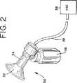
図2は代表的な搾乳器組立体の斜視図である。
図3は本発明の乳房シールド支持体の第1の実施形態の分解斜視図である。
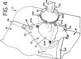
図4は本発明の乳房シールド支持体の第2の実施形態の分解斜視図である。
図5は本発明の乳房シールド支持体の第3の実施形態の分解斜視図である。
図6は本発明の乳房シールド支持体の第4の実施形態の分解斜視図である。
図7は本発明の乳房シールド支持体の第5の実施形態の分解斜視図である。
図8は本発明の乳房シールド支持体の第6の実施形態の分解斜視図である。
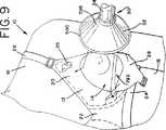
図9は本発明の乳房シールド支持体の第7の実施形態の分解斜視図である。
図10は本発明の乳房シールド支持体の第8の実施形態の分解斜視図である。
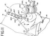
図11は本発明の乳房シールド支持体の第9の実施形態の分解斜視図である。
図12は図11に示す乳房シールドの断面図である。
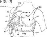
図13は本発明の乳房シールド支持体の第10の実施形態の操作図である。
図14は図13に示す第10の実施形態の部分的に断面で示す立面図である。
図15は本発明の乳房シールド支持体の第11の実施形態の操作図である。
図16は図15に示す第11の実施形態の立面図である。
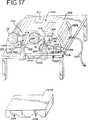
図17は本発明の乳房シールド支持体の第12の実施形態の斜視図である。
図18は本発明の乳房シールド支持体の第13の実施形態の分解斜視図である。
図19は図18に示す第13の実施形態の操作図である。
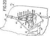
図20は明瞭にするために乳房シールド組立体を取り除いた、本発明の乳房シールド支持体の斜視図である。
図21は本発明の実施形態に使用されるループ配置を示すブラジャーの斜視図である。
図22はバンドの配置を示す図21のブラジャーの斜視図である。
図23は本発明に従って作られた取付け要素及び搾乳器の斜視図である。
図24は図23の取付け要素の側面図である。
図25はバンド/ループを取付けた図24の取付け要素の正面図である。
図26は図25のループの斜視図である。
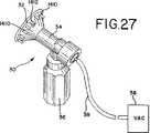
図27は取付け要素が乳房シールドと一体に形成された変形実施形態の図である。
図28は図25の取付け要素と同様な修正した取付け要素の図である。
現時点で好ましい実施形態の詳細な説明
図示を容易にするために、本発明は一般的には、単一の乳房から母乳を搾り出すのに使用される単一の搾乳器について示され且つ説明される。しかしながら、例えば図15に示すように、本発明は母乳の収集のために婦人の乳房の各々で乳房シールドを同時に支持することも特に計画される。加えて、同じ参照番号は本発明のそれぞれの実施形態において同じ要素を指定するのに使用されている。
今、図面を参照すると、図1はブラジャー12を着けている婦人10の部分的な図を示す。ブラジャー12は婦人10の乳房14、胴16及び肩18のまわりに一致して乳房14を支持するようになっている。ブラジャー12は連結バンド22によって相互に連結された2つの乳房カップ20、婦人の背中のまわりに延び、婦人の背中のところで連結される胴バンド24、及びそれぞれの乳房カップ20と胴バンド24の端(図示せず)との間に配置されたショルダー帯26(その内側本体の1つを図示せず)を含む。以上までは、ブラジャー12は在来型である。
本発明を図1に示すブラジャー12について示す且つ説明するとしても、他のタイプのブラジャー、例えば、帯びなしブラジャー、及びホルタートップ、キャミソール等を含む他のタイプの乳房支持被服を以下でさらに理解されるように、本発明に使用することができる。
図1に示すように、乳房カップ20の各々は、それぞれの乳房カップ20の底近くでブラジャー20に連結れれたフラップ28を有する。フラップ28は短い帯29でそれぞれのショルダー帯26に近い位置でブラジャー12に取り外し自在に接続される。フラップ28は、これを肩18から胴16まで移動させるとき搾乳又は搾乳のために乳房14を露出させるようにブラジャー12に配置される。フラップ28は乳房14を露出させるのに適した方法で又はむき戻し状態でブラジャー12に接続される。
本発明に使用される代表的な搾乳器30を図2に示す。搾乳器30は少なくとも乳首及びそれに隣接した乳房の幾らかを受け入れるようになった乳房シールド又はフード32を有する。乳房シールド32は搾り出された母乳を受けてそれをチャンネル34をとおして母乳収集容器36に差し向ける。
本発明は乳房シールドを適所に支持するためのものであるが、殆どの場合ではないが、多くの場合には、これはまた搾乳器の全体(即ち、部品32、34、36及び関連要素)を支持することを必要とする。容器36はいっぱいのとき5オンス程度の母乳を入れるから、支持装置は搾乳器及びいっぱいの容器の重量を心地よく、乳房シールドを搾乳中適切に位置決めした状態で、支持することが出来なければならない。
真空源38は管39を介して乳房シールド32及びチャンネルと連通し、乳房14から母乳を搾り出す吸引作用を乳房シールド32内に生じさせる。真空源38は間欠的な真空を発生させるための電動器駆動式搾乳器真空源からなる。その上、2つの乳房シールド32が両方の乳房14の同時「二重搾乳」のために真空源に接続される。他方の真空源、例えば、電池駆動式ポンプ、手動操作の手駆動式ピストンポンプ、又は圧搾球型ポンプを本発明に使用することができることは勿論である。しかしながら、後者の2つは本発明について特に有利であるとは考えられない。と言うのは、片手又は両手が手動ポンプを操作することで占められからである。電動器駆動式搾乳器、電池駆動式搾乳器、及び手動操作式搾乳器のもっと詳細な説明については、米国特許第4,857,051号及び同第5,007899号を参照しなければならないかもしれない。
図3は本発明の第1の実施形態を示す。図3に示すように、乳房シールド支持体はブラジャー12及び搾乳器30を含む。乳房シールド32はブラジャー12に連結され、そして図3乃至7に示す実施形態では複数のファスナーによって乳房14で支持される。ファスナーは各々ブラジャー12の乳房カップ20に配置されたファスナーエレメントと、乳房シールドと関連した対応するファスナーエレメントとを含む。対応するファスナーエレメントは互いに留められて乳房シールド32をブラジャー12に取り付け、それによって、乳房シールド32を手を使わない仕方で乳房14で支持する。
図3には、ブラジャーカップ20のファスナーエレメントはボタン穴158からなるものとして示され、乳房シールド32のファスナーエレメント156はハーネスからなるものとして示され、支持帯160を持ったハーネスからなるものとして示され、多数の調整可能な帯162が支持帯160に接続されそしてそこから延びている。帯162はそれらの端に、ボタン穴158に挿入するためのボタン164を含む。ハーネスは、該ハーネスを管状部分34上に滑らせ、或いは支持帯160を管状部分の周りに留めることによって(ある平凡な手段を使用して帯160の端を相互に連結することによって(図示せず))乳房シールド32に解放自在に取付けられる。従って、ハーネスの使用には既存の搾乳器の修正は必要とされない。しかしながら、変形例として、乳房シールド32をブラジャー12に連結し、且つ乳房シールド32を乳房14で支持するのに、例えば、ジッパーファスナー、スライド/ダブルバック帯ファスナー、バックル/帯ファスナー、ガータベルトファスナー、マジックファスナー、スナップファスナー、再使用可能な接着テープファスナー、ベルクロ(即ちフックとループ)ファスナー及びホックファスナーを含む多数の異なるファスナーを使用してもよい。
図4は本発明の第2の実施形態を示す。乳房シールド支持体は図3に示す実施形態と大変似ている。しかしながら、ファスナーエレメント254,256が乳房シールド32の周縁に配置されたバンド270に連結される。バンド270は弾性材料で形成されるのがよい。バンド270は摩擦/しまり嵌めによって或いはこの例のように、フック260によって適所に保持される。図4には、対応するファスナーエレメント254、256はベルクロファスナーからなるものとして示されている。しかしながら、上記のように、任意適当なタイプのファスナーを使用してもよい。
図5は本発明の第3の実施形態を示す。再び、図5に示す乳房シールド支持体は図3及び4に示す乳房シールド支持体と構造が大変良く似ている。しかしながら、1つの違いは、乳房シールド32に位置したファスナーエレメントが乳房シールド32の中間領域372に連結されていることである。図5に示す実施形態では、ファスナーエレメントは乳房シールド32に形成され或いは連結されたスタッド又はリベット374と、ブラジャーカップに連結されたスタッド又はリベット354とからなる。調整可能な帯376はファスナーを完成し、各々乳房14上の乳房シールド32のフットを調整させるためにリベット354、374に嵌まる複数の穴378を有する。
図6は本発明の第4の実施形態を示す。この実施形態では、ブラジャー12のファスナーエレメントはフック454からなり、乳房シールド32に位置したファスナーエレメントはフック460によって適所に保持された弾性バンド480からなる。弾性バンド480は乳房シールド32の周縁に配置され、乳房シールド32を乳房14で支持させるためにフックファスナーエレメント454に嵌まるように操作される。
第3図ないし第6図に示すファスナーエレメントの配置をブラジャー12および乳房シールド32上に変え、数を所望に応じて増やしたり減らしたりすることができることは理解すべきである。使用したファスナーの種類は限定されないが、ここに記載のものは最も有利であると思われる。また、ファスナーエレメントをブラジャー12または乳房シールド32上の任意の適当な位置に設置することができる。更に、乳房シールド32に位置決めされたファスナーエレメントを乳房ポンプ30上の任意の他の適当な位置に連結することができる。
第7図に示すように、本発明の第5実施例はブラジャー12のフラップ28に摺動可能に挿通された乳房シールド32を有する。この乳房シールド32は真空下で乳房のまわりに収縮するように比較的可撓性である。乳房シールドおよびフラップ開口部の直径は、乳房シールド32がフラップ28への挿通後に乳房14とブラジャー12の乳房カップ20の内面との間で乳房14に支持されるように寸法決めされている。すなわち、フラップ28の一部(すなわち、乳房14の底部)と、乳房14の露出部分を取り囲む乳房カップ20の材料と、乳房シールド32の硬化周線部590とが協働して乳房シールド32を乳房14に支持する。
第7図の実施例の変形例を示す第8図において、フラップ629は(男性用ブリーフに見いられるものと同様な)2つの重なり部分691、692を備えており、それらの各々はブラジャー612の乳房カップ620に連結されている。乳房シールド(図示せず)は、まず乳房シールドをフラップ628の一部691を通り越して挿入し、次いで乳房シールドを他の部分692を通り越してその下方で摺べらすことによって乳房14に支持される。フラップ628の部分691、692と、乳房カップ620の材料と、乳房シールド(図示せず)が協働して乳房シールドを乳房14に支持する。以上に示したフラップ628は乳房カップ620上に垂直に配向されており、フラップ628は水平を含めて任意の適当な方向に配向することができる。
本発明の更に他の実施例は第7図に示すものと非常に類似する構成を持つブラジャー12を有している。しかしながら、第9図に示すブラジャー12はフラップ28が連結する乳房カップ20の底部に配置される半剛性材料のフランジ793を有している。第7図を参照して以上に説明したように、乳房シールド32をフラップ28に挿通すると、フランジ793は乳房シールド32を乳房14に更に支持するように機能する。
第7図および第9図に示す実施例では、搾乳器30の乳房シールド32は上記のように、実質的に剛性な周縁部590および実質的に可撓性(例えば、コンドーム状)の内部領域595を有する。可撓性領域595により、乳房シールド32をフラップ28に容易に挿通し、乳房の形状に容易に一致させることができる。剛性の周縁部590はフラップ28および乳房カップ20の内面と協働して乳房シールド32の乳房に対する改良支持を行う。逆に、乳房シールド32を乳房14に支持するために、周縁部590が実質的に可撓性であり、内部領域595が実質的に剛性であってもよい。
第10図に示すように、本発明の第8実施例は十字形重なり部分803が構成された乳房カップ20を有している。乳房シールド32はこれを十字形重なり部803およびまわりの乳房カップ20の材料の下に挿入することによって乳房14に支持される。十字形重なり部803と、まわりの乳房カップ20の材料と、乳房シールド32とが協働して乳房シールド32を乳房14に支持する。また、乳房カップ20には、調整可能な帯805が、例えば、ホック・アンド・アイファスナー809により取付けられている。帯805は留め要素807を経て調整可能なショルダー帯び26に連結されて乳房カップ20を乳房に支持する。乳房シールド32を乳房カップ20の十字形重なり部803の下に挿入した後、乳房カップ20上の帯805の位置をファスナーを介して調整して乳房に対する乳房シールド32のフィットを調整する(すなわち、乳房14に対する乳房カップ20のフィットをきつくしたり緩めたりする)。
第10図に示す実施例の変形例を示す第11図および第12図において、乳房シールド32はその周囲に配置された実質的に剛性のリム903を有する。リム903は、乳房シールド32を十字形重なり部803および周囲の乳房カップ20の材料の下に挿入すると、涙滴状部分905が十字形重なり部803の下に嵌まるように乳房シールド32に位置決めされる。リム903、特に、その涙滴状部分905により、乳房シールド32を乳房14に支持し易くする追加の表面領域を乳房シールド32に設ける。リム903は、例えば、リム903の嵌合い用環状凹部に嵌まるシールドの周囲のビーズ904とのスナップ嵌めにより乳房シールド32に連結される。また、乳房シールド32を乳房14に更に支持するために、涙滴状部分905および乳房カップ20に、例えば、乳房シールド32を乳房カップ20の材料の下に挿入すると、互いに留められる嵌め合いスナップ留め要素(図示せず)を設けることができる。
第11図および第12図に示す実施例の変形例では、乳房シールド32を乳房14に更に支持するために、ブラジャー12はショルダー帯26に連結された追加の調整可能な支持帯995を有する。支持帯995は、これを必要時に引き出すことができるブラジャー12の乳房カップ20の下に位置決めされる。支持帯995はボタン穴型開口部996を有し、またバックル997によってショルダー帯26に調整可能に連結されている。ホック998を任意の適当な方法で乳房シールド32またはリム903に成形したり連結したりする。乳房シールド32を十字形重なり部803の下に挿入した後、支持帯995をホック998に取付けて乳房シールド32を更に支持する。もちろん、次いで、支持帯995を調整して乳房14に対する乳房シールド32のフィットを調整することができる。
第13図および第14図は本発明の第10実施例を示している。雌ランナ帯びのようなホールタトップ被服1010は婦人の胴のまわりに嵌まるようになっているバンド1012と、バンド1012に連結され、且つ婦人の乳房に一致するようになっている2つの乳房カップ20と、各々がバンド1012と乳房カップ20との間に連結され、且つブラジャーのようにして婦人の肩のまわりに位置するようになっている2つのショルダー帯とを有している。
被服1010は授乳或いは搾乳のために婦人が乳房14を露出するように作用できるフラップ28を有している。フラップ28は乳房カップ20の底部に沿って被服1010に連結されており、且つショルダー帯1018(点A)および乳房カップ20の頂部(点B)のところで被服1010に取外し可能に連結されている。この構成では、フラップ28は、これをショルダー帯1018から被服1010の底部まで移動させると、乳房を露出するように作用する。しかしながら、変更例として、フラップ28は任意の適当な方法で乳房を露出するように被服1010に配向されてもよい。この実施例では、フラップ28はベルクロファスナーにより被服1010に連結されている。また、任意の適当な種類のファスナーを使用し得る。
第14に示すように、被服1010はその内面に連結された帯1022を有する。帯1022は実質的に乳房カップ20の背後に位置決めされている。帯1022は各々が異なる位置で被服に取付けられる3つの脚部または部分1024a〜1024cを有する。
搾乳を望む場合、フラップ28を被服1010から外して乳房を露出する。帯1022を、フラップ28により構成された開口部を通って延びるように被服1010の内部から抜き取る。搾乳器30を乳房14の近くに置き、帯1022を延ばし、そして乳房シールド32を通ってこれを乳房14に支持するように搾乳器30のまわりに帯1022を嵌める。これは帯部分1024a、1024bにより構成されたループを取り、このループを搾乳器30の後部分の下で且つ瓶36(第13図)と連結する下方に延びる部分の背後に置くことによってなされる。帯部分1024cは上記ループを適所に固定するっように機能する。次いで、帯部分1024a〜1024cを調整して乳房シールド32が乳房に対して心地好くではないが滑り嵌まりする。調整は弾性帯1022および/または調整可能なエックステンダーを相互連結箇所に設けることによって達成することができる。
第15図および第16図は本発明の第11実施例を示している。このハーネス被服1110は胴に嵌まるようになっているバンド1112と、各乳房14用の2つの調整可能な帯構造体1140a、1140bとを有する。バンド1112は、例えば、ベルクロファスナー1138により婦人の背中で互いに連結される2つの端部を有する。帯1140a、1140bは各々、バンド1112に連結された第1端部1142と、ホックファスナー1145のところで互いに連結可能な第2端部1144とを有する。第15図に示すように、第2端部1144は婦人の首の背後で互いに連結される。変更例として、第2端部1144はブラジャーのショルダー帯(図示せず)に連結される。また、第16図に示すように、各帯1140a,1140bの第1端部1142は、例えば縫うことによってバンド1112に連結される2つの脚部または部分1146a、1146bを有する。夫々の端部1142の2つの脚部1146a、1146bはバンド1112上で間隔を隔てられており、ここでは、一対のループに連続した材料片から構成されている。
帯1140a、1140bは乳房14に静止したり圧接したりするようになっている2つの閉鎖乳房ループ1148a、1148bを有する。第15図に示すように、乳房ループ1148a、1148bは、各々、露出乳房14のまわりに嵌まり、且つ乳房シールド32を露出乳房14に保持するように寸法決めされている。各乳房ループ1148a、1148bはリングコネクタ1152を経て各一対の脚部1146a、1146b(各対はループを構成する)に連結されている。
使用にあたり、搾乳器30をループ1148aのような夫々の乳房ループの近くに置き、第10実施例について先に説明した方法でループ1148aを延ばし、且つ搾乳器30のまわりに嵌めて、ループ1148aが乳房シールド32を乳房に押し当てて支持するようにする。次いで、調整バックル1150を介して帯1140a、かくしてループ1148aを調整して乳房シールド32が乳房14にぴったり嵌まるようにする。各脚部1146a上の同様なバックル1154により、脚部1146a、1146bにより構成されたループの調整を可能にする。
第15図に示すように、二重搾乳を望む場合、各乳房ループ1148a、1148bを延ばし、別体の搾乳器30のまわりに嵌めて乳房シールド32を乳房14に支持する。
本発明の第10および第11実施例をホールターおよびハーネス被服1010、1110に関して以上に示して説明したが、特に、幾つかを挙げると、標準ブラジャー、無帯ブラジャー、カミソールおよびタンクトップを含めて任意の適当な種類の被服を本発明で使用することができる思われる。更に、帯1022、1140a、1140bを含めてハーネスおよびホールタートップ被服1010、1110を任意の適当な弾性材料またはたの材料で構成してもよい。
第17図は本発明の第12実施例を示している。乳房シールド支持体1210はベース部材1212を有しており、このベース部材1212には、2つの乳房シールド32がエアチューブ1214により連結されており、エアチューブ1214の各々は可撓性部分1216および剛性部分1218を有している。エアチューブ1214の剛性部分1218は乳房シールド1218をベース部材の上方にこれから離して支持し、また可撓性部分1216により、婦人が乳房シールド1218を彼女の乳房上に調整して、ぴったりし、それでも心地好い嵌め合いを確保することができる。
各乳房シールド32のエアチューブ1214は在来の結合構造を介してベース部材1212の外方に位置決めされた母乳収集容器1220に連結される。変更例として、収集容器1220はベース部材1212の内側に位置決めしてもよい。
以下に説明するように、エアチューブ1214はベース部材1212に位置決めされた真空源1222を乳房シールド32に連結して乳房シールド32に吸引作用を生じる。搾乳中に乳房から絞り出された母乳を収集容器1220に収集する。搾乳が終了した後、収集容器1220をエアチューブ1214から外し、母乳を保管のために取り出す。
米国特許第4,929,229号に記載のように、乳房シールド32は各々、内部バッフルおよび弁を有している。バッフルおよび弁は協働して母乳をエアチューブ1214を通して収集容器1220の中へ差し向け、かくして母乳が収集容器1220を越えてベース部材1212の中へ延びるエアチューブ1214の部分へ引き入れられるのを防ぐ。
継手1219が各エアチューブ1214の剛性部分1218をベース部材1212に連結して乳房シールド32を適所に保持する。エアチューブ1214はベース部材1212の前壁部1221を通り、真空源1222で終わっている。エアチューブ1214は在来のコネクタ1223により真空源1222に連結されている。継手1219およびコネクタ1223により、使用者は清浄、修理および/または交換のためにエアチューブ1214および乳房シールド32を乳房シールド支持体1210から外すことができる。乳房シールド支持体1210の内部への接近はパネル1211により行われる。
エアチューブ1214の各々は液体および/または細菌フィルタ1225を有する。液体フィルタは母乳または他の液体がエアチューブ1214を通って真空源1222を損傷するのを防ぐ。細菌フィルタは絞り出された母乳がエアチューブ1214および真空源1222に存在するかも知れない細菌により汚染されるのを防ぐ。
乳房シールド支持体1210は真空源1222に接続された電力コード1227を有する。電力コード1227は電源(図示せず)に接続されて真空源1222を駆動する。また、乳房シールド支持体1210は、外部電力源が容易には利用できない場合、或いは電源を遮断した場合に真空源に電力を供給するバッテリを有するのがよい。
ベース部材1212は真空源1222と関連された真空制御ノブ1231を有する。この制御ノブ1231を操って真空源1222により夫々の乳房シールド32に生じられた吸引を増減することができる。
別の実施例では、可撓性および/または枢動可能な支持アーム(図示せず)により揺り籠状装置(図示せず)がベース部材1212に取りつけられる。第13図に示すような乳房シールド32および配管が揺り籠状装置に保持され、搾乳のために婦人の乳房に支持される。
ベース部材1212はテーブル1224の頂上に支持されており、婦人はハンドフリーの「二重搾乳」のためにベース部材1212の隣に座ったり立ったりし、乳房シールド32を乳房の位置決めすることができる。
乳房シールド支持体1210を支持するのにテーブル1224の代わりに、使用者の脚を受け入れるための凹領域1228を有する膝支持体1126を使用してもよい。座ったままで乳房ポンギングをしたい婦人が彼女の膝に膝支持体1226を位置決めし、乳房シールド支持体1210を膝支持体1226に載置することができる。次いで、乳房シールド32を搾乳のための乳房の適所に操つる。
第18図および第19図は第11図および第12図に示す実施例の変形例である本発明の第13実施例を示している。図示のように、ブラジャー12はショルダー帯26に連結された調整可能な支持帯1372を有する。支持帯1372は、必要とされるときに帯1372を引き出すことができるブラジャー12の乳房カップ20の下に位置決めされる。支持帯1372はボタン1374と、これに沿って間隔を隔てられたボタン穴型開口部1376とを有しており、またバックル1378によってショルダー帯26に調節可能に連結されている。乳房シールド32を乳房カップ20に下に挿入した後、支持帯1372を乳房シールドチャンネル34のまわりに延ばし、(ボタン1374およびボタン穴1376を介して)それ自身に取付けて乳房シールド32を乳房14に支持する。もちろん、第19図に示すように、次いで、支持帯1372をバックル1378を介して)調整して乳房14に対する乳房シールド32の嵌め合わせを調整することができる。
別の実施例では、支持帯1372をループに形成し、それによりボタン1374およびボタン穴1376を不要にすることができる。更に、支持帯1372を弾性化してもよい。また、ボタン1374およびボタン穴1376の構成の代わりに、任意の適当な種類のファスナーを使用してもよい。
第20図は本願の本発明の第1実施例を示している。乳房シールド/組立体支持体はブラジャー12と、取付け要素1400と、取付け要素用の付属品を有する。第23図に示すように、取付け要素1400はこれを乳房シールド32のまわりにすべり嵌めすることにより乳房シールド32に連結されるか、或いは取付けられる。これはこの実施例では、スリップオン嵌めまたはスナップ嵌めで乳房シールド組立体のチャンネル部分34のまわりに嵌まる取付け要素の環状の部分円筒形部分1401で達成される。更に、取付け要素1400は乳房シールド32の背面のシェル部分に合致するように収容されたシェル部分1402を有する。切欠き1404が円筒形チャンネル部分34に対する取付け要素のスナップ嵌めを受け入れる。取付け要素は搾乳器シリンダ部分34の上方を通り、次いでこの部分34を取り囲むように割り管状部分1401を広げるのに十分な可撓性を有する剛性プラスチックで作られている。取付け要素1400はブラジャー12に連結されており、以後によりはっきり示すように、複数のループおよびバンドにより乳房14に支持される。第21図を参照すると、ループ1406はブラジャー12の乳房カップ20に連結されている。ループ1406は布製であり、乳房カップ20に縫い込まれている
バンド1408(第22図)はループ1406に永久的に取付けられてもよいし、或いは現在のところ好ましいように、バンド1408をループ1406に取外し可能に取付けてもよい。バンド1408がループ1406に取外し可能に取付けられる実施例では、バンド1408をループ1406に挿通し、次いで、ループ1406に挿通された方のバンド1408の端部をバンド1408の他端部の開口部に挿通し、それによりバンド1408をループ1406に取外し可能に結ぶ。バンド1408はゴムバンドのような弾性材料のものである。
第24図に最も良く示すように、取付け要素1400はそのシェル部分1402の周囲に規則的な間隔で優先的に位置決めされた複数のポスト1410を有する。これらの部分1410はシェル部分1402に対して後方に延びている。取付け要素が適所にある状態で(第20図)、バンド1408は、婦人10が搾乳器30を支持するのに彼女の手を使用しなくてもよいように、搾乳器30を乳房14に当てて支持するようにしてポスト1410のまわりに設置される。設けられたポスト1410の数により、バンド1408の容易且つ種々の取付けを可能にする。
縫い込みループ1406を介しての2つの取付け箇所に加えて、取付け要素はホック1412を介しての更にの取付け箇所を有する。
ホック1412は取付け要素1400および取付けられた搾乳器を配向させるように設けられており、ホック1412は上向きであり、すなわち、乳房の上方にある。これにより、特に搾乳中に瓶が一杯になると、重量/トルクの大半が加えられ場合に、より確実な取付け箇所が得られる。また、第20図でわかるように、ポスト1410は取付け要素を適所に固着するためにホック1412とともに使用してもよい。
布ループ1406'はホック1412に取付けられるバンド1408と関連されている。そのループ1406'は先に述べたようにしてこのバンドに取外し可能に取付けられる。しかしながら、ショルダー帯26に固着すべきであるループ1406'は、例えば、これをバンドのまわりに縫い合わせることによって、これらの図に示すように、そのバンド1408に永久的に取付けてもよい。ループ1406は第26図の示すように、ホックファスナー1414を使用してショルダー帯26に取外し可能に取付けられる。ショルダー帯26は対応するアイファスナー1415を有する。ホックファスナー1414および対応するアイファスナー1415により、布ループ1406'をショルダー帯26に取外し可能且つ調整可能に取付けることができる。
第27図に示す他の実施例では、ポスト1410およびホックを一体に形成した乳房シールド32を構成することによって、取付け要素を除去することができる。第28図は取付け要素1400の変更態様を示しており、この場合、ホック1412を機能上、リブ1417を間に構成する一対の平行スロット1416と交換してある。布ループについて述べたようにしてバンド1406'をリブ1417に取外し可能に結ぶことができる。リブ1417は本質的にホックである。
上述のように、本発明によれば、授乳する養母が自分の手を自由の使用して他の仕事または雑用を行いながら、搾乳器を使用して母乳を収集して貯えることができる。また、本発明によれば、手を使わない「二重搾乳」を行うことができる。更に、本発明は使用が簡単であり、乳房シールドを露出乳房に素早く支持することができる。
本発明は適用に適切であるように変更したり、構成したりすることができることはわかるべきである。上記の実施例はあらゆる点において例示的なものであって、限定するものではないと考えるべきである。本発明の精神を逸脱することなしに変更例を行うことができる。本発明の範囲は上記説明によってではなく、下記の請求項によって指示される。文字上の意味ならびに請求項の同等のものの範囲に入るあらゆる変更例がそれらの範囲内に包含されるべきである。Background of the Invention
The present invention relates generally to breast pumps, and more particularly to a device for supporting a breast shield and associated breast pumps in a woman's breast.
Milking machines for squeezing and storing breast milk for later use are well known. In general, two types of breast pumps are available for use by foster mothers: motor driven breast pumps and manual breast pumps. Typically, these breast pumps have a funnel-shaped shield or hood that fits over the nipple and some vacuum pumps connected to the breast shield to generate an intermittent vacuum within the breast shield (e.g., A manual piston cylinder, a squeezing ball (valve), or an electric vacuum device) and a milk milk container. Intermittent suction generated by a vacuum pump in the breast shield pulls or pushes the breast, mimicking the infant's sucking action, thereby pumping milk from the breast. The expressed milk typically flows from the breast shield to a collection container for storage and subsequent use by infants. A collection container, such as a small milk bottle, is usually incorporated into the breast shield, for example via a channel for mid-milk and a valve device.
Bras, holder tops, and other clothing specifically designed for foster mothers are also well known. In general, these nursing bras have a flap that can be removed from the bra on one side to expose the breast for feeding by an infant or to allow breast pump collection.
When it is desired to collect and store breast milk using a breast pump while wearing a nursing bra or something else, after the breast is exposed, the mother holds the breast shield in place with the breast shield exposed. Obviously, depending on whether the milking machine is motorized or operated by hand, and depending on whether one or two breast shields are being used at the same time, one of the mothers can perform the milking operation. Requires hands or both hands. As can be readily seen, whether at home or at work, a foster mother cannot use at least one hand to perform other tasks when using a breast pump. Therefore, it would be advantageous to develop a method and apparatus that allows a mother to use a breast pump while allowing her mother to use her hand for other tasks.
Summary of the Invention
It is a primary object of the present invention to provide an apparatus for supporting a breast pump's breast shield with an exposed breast without the user's hands. Related methods are also provided. As disclosed below, the present invention, in its broadest sense, is a non-animal means for holding a breast shield in place on the breast without requiring a user or someone else to hold the breast shield in place. I will provide a. The breast shield support is supported on the mother's body or on a base that can be moved to position the shield, and the mother can insert the breast.・ ・ ・ ・ ・ ・
In one aspect of the invention, such a support method and apparatus provides a brassiere or other similar garment that serves as a base, and means for supporting the breast shield at the breast with exposure associated with the base.
In one embodiment, the support means takes the form of a releasable fastener mechanism having interengaging fastener elements on the brassiere and breast shield. The brassiere has a hole in the cup, such as made by a flap, that exposes the breast for breast pump breast shield installation. Corresponding fastener elements of the brassiere and breast shield are fastened together to support the breast shield with the exposed breast.
Various fastening mechanisms can be employed. For example, a releasably attached harness of a breast shield has a band that is releasably fastened to a brassiere / base by, for example, a hook, button, snap, or the like. In other embodiments, the breast shield is integrally formed on the parts of the fastening mechanism.
According to another embodiment of the invention, the support means take the form of a flap and a flap opening, especially found in brassiere garments adapted to hold the breast shield in place. For example, the opening provided in the flap is of at least one dimension smaller in diameter than the breast shield. The breast shield is inserted and received in the opening such that the breast shield is supported by the breast exposed between the breast and the inner surface material of the brassiere. The flap may be reattached for further support of the breast shield. As an alternative, to adjust the breast shield foot and support the breast shield with the breast, an additional adjustable band with one end connected to the brassiere shoulder band and the other end connected to the breast shield is inserted. May be.
In related embodiments, the overlapping portions of material form a brassiere cup. The breast shield is inserted into the opening provided by the overlap and then held in place on the breast by the brassiere cup. In other related embodiments, the breast shield comprises a tear-shaped rim that increases the surface area of the breast shield and functions to better support the breast shield at the breast. Often the rim can be removably attached to the breast shield. In addition, the breast cup and teardrop shaped rim may further comprise a fastener element that connects the breast shield to the breast cup.
In yet other embodiments, the flap is removed from the brassiere to expose the breast and install the breastshield to the breast, and then reattached to the brassiere to support the breastshield with the breast. The flap may further comprise a small hole for receiving a breast shield tubular extension, tube or other breast pump device extending from the breast shield.
In another aspect of the invention, a breast shield support method and apparatus utilizes a band structure for supporting and holding a breast shield of a breast pump with an exposed breast. Preferably, the device is configured to hold two breast shields, each of which is supported on the respective breast by a band structure.
In one embodiment, the breast shield support device comprises a garment having one or more bands adapted to position the breast shield, preferably adapted to press the breast shield against the breast. Such clothing comprises, for example, a harness having a band portion adapted to wrap around the torso and at least one band adapted to support the breast shield with one of the breasts. For example, the breast shield is held on the exposed breast with a band that engages a breast pump outside the breast shield and holds the breast shield to the breast. In one such embodiment, the band forms a loop that holds the breast shield to the breast shield and supports the breast pump. At the top, the rope is attached to a base like a shoulder band. An auxiliary band connects the lower part of the loop to the torso band to secure the milking machine and press it into place. It is advantageous to provide a three-point adjustable fixing device for the harness.
In another embodiment, the breast shield support device is adapted for use with a female motion top having a waistband portion and a brassiere portion. The breast shield support band extends from the shoulder to the sternum region to form a loop that receives the breast shield. It is advantageous to provide an auxiliary band for fixing the loop to the waistband part. The brassiere cup is formed with a flap for access to the breast and the band structure described above, which is located within the brassiere part for breast shield installation using the band structure.
In yet another aspect of the present invention, a mounting device is provided for the use of the breast shield, which device is not supported by humans. For example, breast shields are supported with a milking mechanism so that the mother inserts the breast into each breast shield. The milking mechanism independently supports the breast shield.
According to the present invention, a breastfeeder collects and stores milk using a breast pump without using hands at home or at work. In addition, the present invention allows milk to be pumped from both breasts simultaneously using a hands-free “double milking” or two breast shields. Also, embodiments using bands and band fasteners preferably employ adjustable bands to adjust the breast shield foot or tightness at the breast. Furthermore, the present invention is easy to use and allows the breast shield to be quickly supported by the exposed breast.
The present invention is directed to further variations on the inventive concept. In one form, embodiments of the invention have attachment elements that fit on the back of the breast shield. The mounting element has a post. A fabric loop is sewn to the bra. A band, such as a rubber band, is tied to the fabric loop and otherwise attached. The band is then placed around the post of the mounting element to support the breast pump in place with the breast, so that the mother does not need to use his hands to support the breast pump.
The above embodiments preferably use a slip-on or snap-on attachment element with a contour that matches the shape of the back portion (back portion) of the breast shield. Thus, the attachment element can be easily attached or removed. It is advantageous to further provide a plurality of posts that facilitate the adjustment and attachment of the band.
In a variant of the invention, the mounting element post may be integrally formed with the breast shield.
The attachment element, band and / or fabric loop may be provided in the form of a kit. Thereby, the mother can modify the existing breastfeeding bra for the breast pump assembly support according to the present invention.
These and other features and advantages of the present invention will be further understood when considering the following detailed description taken in conjunction with the accompanying drawings.
[Brief description of the drawings]
FIG. 1 is a perspective view of a brassiere in use showing the brassiere flaps in a removal mode that exposes the breast for breastfeeding or milking.
FIG. 2 is a perspective view of a typical breast pump assembly.
FIG. 3 is an exploded perspective view of the first embodiment of the breast shield support of the present invention.
FIG. 4 is an exploded perspective view of a second embodiment of the breast shield support of the present invention.
FIG. 5 is an exploded perspective view of a third embodiment of the breast shield support of the present invention.
FIG. 6 is an exploded perspective view of a fourth embodiment of the breast shield support of the present invention.
FIG. 7 is an exploded perspective view of a fifth embodiment of the breast shield support of the present invention.
FIG. 8 is an exploded perspective view of a sixth embodiment of the breast shield support of the present invention.
FIG. 9 is an exploded perspective view of a seventh embodiment of the breast shield support of the present invention.
FIG. 10 is an exploded perspective view of an eighth embodiment of the breast shield support of the present invention.
FIG. 11 is an exploded perspective view of a ninth embodiment of the breast shield support of the present invention.
12 is a cross-sectional view of the breast shield shown in FIG.
FIG. 13 is an operation diagram of the tenth embodiment of the breast shield support of the present invention.
FIG. 14 is an elevational view partially shown in section of the tenth embodiment shown in FIG.
FIG. 15 is an operation diagram of the eleventh embodiment of the breast shield support of the present invention.
FIG. 16 is an elevation view of the eleventh embodiment shown in FIG.
FIG. 17 is a perspective view of a twelfth embodiment of the breast shield support of the present invention.
FIG. 18 is an exploded perspective view of a thirteenth embodiment of the breast shield support of the present invention.
FIG. 19 is an operation diagram of the thirteenth embodiment shown in FIG.
FIG. 20 is a perspective view of the breast shield support of the present invention with the breast shield assembly removed for clarity.
FIG. 21 is a perspective view of a brassiere showing a loop arrangement used in the embodiment of the present invention.
22 is a perspective view of the brassiere of FIG. 21 showing the arrangement of the bands.
FIG. 23 is a perspective view of a mounting element and breast pump made in accordance with the present invention.
24 is a side view of the mounting element of FIG.
FIG. 25 is a front view of the attachment element of FIG. 24 with the band / loop attached.
FIG. 26 is a perspective view of the loop of FIG.
FIG. 27 is an illustration of an alternative embodiment in which the attachment element is integrally formed with the breast shield.
FIG. 28 is a view of a modified mounting element similar to the mounting element of FIG.
Detailed description of the presently preferred embodiment
For ease of illustration, the present invention is generally shown and described for a single breast pump that is used to express breast milk from a single breast. However, as shown for example in FIG. 15, the present invention is also specifically planned to support a breast shield simultaneously in each of the women's breasts for the collection of breast milk. In addition, the same reference numbers are used to designate the same elements in each embodiment of the invention.
Referring now to the drawings, FIG. 1 shows a partial view of a
Although the present invention is shown and described with respect to the
As shown in FIG. 1, each
A
The present invention is intended to support the breast shield in place, but in most cases it is also often the whole breast pump (
The
FIG. 3 shows a first embodiment of the present invention. As shown in FIG. 3, the breast shield support includes a
In FIG. 3, the fastener element of the
FIG. 4 shows a second embodiment of the present invention. The breast shield support is very similar to the embodiment shown in FIG. However, the
FIG. 5 shows a third embodiment of the present invention. Again, the breast shield support shown in FIG. 5 is very similar in structure to the breast shield support shown in FIGS. However, one difference is that the fastener element located on the
FIG. 6 shows a fourth embodiment of the present invention. In this embodiment, the fastener element of the
It should be understood that the arrangement of the fastener elements shown in FIGS. 3-6 can be varied over the
As shown in FIG. 7, the fifth embodiment of the present invention has a
In FIG. 8 showing a variation of the embodiment of FIG. 7, the flap 629 comprises two overlapping
Yet another embodiment of the present invention includes a
In the embodiment shown in FIGS. 7 and 9, the
As shown in FIG. 10, the eighth embodiment of the present invention has a
In FIGS. 11 and 12 showing a variation of the embodiment shown in FIG. 10, the
In a variation of the embodiment shown in FIGS. 11 and 12, the
13 and 14 show a tenth embodiment of the present invention. A female top-like
As shown in FIG. 14, the
If milking is desired,
15 and 16 show an eleventh embodiment of the present invention. This
The
In use, the
As shown in FIG. 15, when double milking is desired, each
While the tenth and eleventh embodiments of the present invention have been shown and described above with respect to the halter and harness
FIG. 17 shows a twelfth embodiment of the present invention. The
The
As will be described below, the
As described in US Pat. No. 4,929,229, each
A fitting 1219 connects the
Each
In another embodiment, a cradle device (not shown) is attached to the
Instead of the table 1224 to support the
18 and 19 show a thirteenth embodiment of the present invention which is a modification of the embodiment shown in FIG. 11 and FIG. As shown, the
In another embodiment,
FIG. 20 shows a first embodiment of the present invention of the present application. The breast shield / assembly support includes a
Band 1408 (FIG. 22) may be permanently attached to
As best shown in FIG. 24, the mounting
In addition to the two attachment points via
A
The
In another embodiment, shown in FIG. 27, the mounting element can be removed by constructing a
As described above, according to the present invention, breastfeeding mothers can collect and store breast milk using a breast pump while performing other work or chores using their hands freely. Further, according to the present invention, “double milking” without using hands can be performed. Furthermore, the present invention is simple to use and can quickly support a breast shield on an exposed breast.
It should be understood that the present invention can be modified and configured as appropriate for the application. The above examples are to be considered in all respects only as illustrative and not restrictive. Modifications can be made without departing from the spirit of the invention. The scope of the invention is indicated by the following claims rather than by the foregoing description. All changes that come within the meaning of the letters as well as the equivalents of the claims are to be embraced within their scope.
Claims (15)
Translated fromJapanese人体に支持されるようになっていて、且つ乳房を露出させるための手段を有するベースと、
前記乳房シールドを乳房に支持するための手段と、を有し、前記支持するための手段は、前記ベースに連結されるようになったファスナーエレメントからなることを特徴とする前記装置。A device for supporting a breast shield of a breast pump,
A base adapted to be supported by the human body and having means for exposing the breast;
Means for supporting the breast shield to the breast, the means for supporting comprising a fastener element adapted to be coupled to the base.
人体に支持されるようになっていて、且つ乳房を露出させるための手段を有するベースと、
前記乳房シールドが乳房に支持されるように搾乳器の一部を前記ベースに取りつけるための手段と、を有することを特徴とする前記装置。A device for supporting a breast shield of a breast pump to a breast,
A base adapted to be supported by the human body and having means for exposing the breast;
Means for attaching a portion of a breast pump to the base such that the breast shield is supported by the breast.
Applications Claiming Priority (5)
| Application Number | Priority Date | Filing Date | Title |
|---|---|---|---|
| US08/375,977 | 1995-01-20 | ||
| US08/375,977US5514166A (en) | 1995-01-20 | 1995-01-20 | Device and method for supporting a breast shield and related pump equipment |
| US08/555,151US5575768A (en) | 1995-01-20 | 1995-11-08 | Device and kit for supporting a breast shield and related pump equipment |
| US08/555,151 | 1995-11-08 | ||
| PCT/US1996/000857WO1996022116A1 (en) | 1995-01-20 | 1996-01-18 | Device and method for supporting a breast shield and related pump equipment |
Publications (2)
| Publication Number | Publication Date |
|---|---|
| JPH10512477A JPH10512477A (en) | 1998-12-02 |
| JP3609832B2true JP3609832B2 (en) | 2005-01-12 |
Family
ID=27007263
Family Applications (1)
| Application Number | Title | Priority Date | Filing Date |
|---|---|---|---|
| JP52242896AExpired - Fee RelatedJP3609832B2 (en) | 1995-01-20 | 1996-01-18 | Device for supporting breast shield and associated breast pump |
Country Status (4)
| Country | Link |
|---|---|
| JP (1) | JP3609832B2 (en) |
| AU (1) | AU4763996A (en) |
| CA (1) | CA2167622C (en) |
| WO (1) | WO1996022116A1 (en) |
Cited By (1)
| Publication number | Priority date | Publication date | Assignee | Title |
|---|---|---|---|---|
| JP2017527337A (en)* | 2014-07-22 | 2017-09-21 | エクスプロラメッド・エヌシー7・インコーポレイテッドExploramed Nc7, Inc. | Milking pump system and method |
Families Citing this family (37)
| Publication number | Priority date | Publication date | Assignee | Title |
|---|---|---|---|---|
| US20060074379A1 (en)* | 2004-09-21 | 2006-04-06 | Hunt Jill M | Milk bag with pump attachment strap |
| US8057408B2 (en) | 2005-09-22 | 2011-11-15 | The Regents Of The University Of Michigan | Pulsed cavitational ultrasound therapy |
| US10219815B2 (en) | 2005-09-22 | 2019-03-05 | The Regents Of The University Of Michigan | Histotripsy for thrombolysis |
| US7950980B2 (en)* | 2006-10-19 | 2011-05-31 | Medela Holding Ag | System and device for supporting a breast shield |
| WO2009124199A1 (en)* | 2008-04-03 | 2009-10-08 | Lyndon Brittner | Hands-free breast pump system |
| US8945046B2 (en) | 2008-04-03 | 2015-02-03 | Lyndon Brittner | Hands-free breast pump system |
| CA2650723C (en) | 2009-01-22 | 2015-11-24 | Wendy Corinne Bell | Breast pump support |
| WO2011022411A2 (en)* | 2009-08-17 | 2011-02-24 | Histosonics, Inc. | Disposable acoustic coupling medium container |
| JP5863654B2 (en) | 2009-08-26 | 2016-02-16 | リージェンツ オブ ザ ユニバーシティー オブ ミシガン | Micromanipulator control arm for therapeutic and image processing ultrasonic transducers |
| JP5726191B2 (en) | 2009-08-26 | 2015-05-27 | リージェンツ オブ ザ ユニバーシティー オブ ミシガン | Apparatus and method using control of bubble turbidity cavitation phenomenon during fracture of ureteral stones |
| ES2543612T3 (en) | 2009-09-22 | 2015-08-20 | Medela Holding Ag | Chest cup for extracting human breast milk |
| JP2012019952A (en)* | 2010-07-14 | 2012-02-02 | Tokyo Univ Of Science | Milking pad and milking device using the same |
| CH703813A1 (en) | 2010-09-17 | 2012-03-30 | Medela Holding Ag | Membrane vacuum pump. |
| US9144694B2 (en) | 2011-08-10 | 2015-09-29 | The Regents Of The University Of Michigan | Lesion generation through bone using histotripsy therapy without aberration correction |
| WO2013166019A1 (en) | 2012-04-30 | 2013-11-07 | The Regents Of The University Of Michigan | Ultrasound transducer manufacturing using rapid-prototyping method |
| US20140100459A1 (en) | 2012-10-05 | 2014-04-10 | The Regents Of The University Of Michigan | Bubble-induced color doppler feedback during histotripsy |
| EP3016594B1 (en) | 2013-07-03 | 2023-01-25 | Histosonics, Inc. | Histotripsy excitation sequences optimized for bubble cloud formation using shock scattering |
| WO2015003154A1 (en) | 2013-07-03 | 2015-01-08 | Histosonics, Inc. | Articulating arm limiter for cavitational ultrasound therapy system |
| US10780298B2 (en) | 2013-08-22 | 2020-09-22 | The Regents Of The University Of Michigan | Histotripsy using very short monopolar ultrasound pulses |
| US11660380B2 (en) | 2014-07-22 | 2023-05-30 | Willow Innovations, Inc. | Breast pump system with collection container |
| CN110314257B (en) | 2014-07-22 | 2022-10-28 | 威洛创新股份有限公司 | Breast pump system and method |
| CN104888290A (en)* | 2015-01-28 | 2015-09-09 | 梁祈牵 | Auxiliary fixing device for feeding bottle |
| JP6979882B2 (en) | 2015-06-24 | 2021-12-15 | ザ リージェンツ オブ ザ ユニヴァシティ オブ ミシガン | Tissue disruption therapy systems and methods for the treatment of brain tissue |
| US9706796B2 (en)* | 2015-08-12 | 2017-07-18 | Medela Holding Ag | Hands free pumping bustier |
| AU2017217702B2 (en) | 2016-02-10 | 2022-02-03 | Willow Innovations, Inc. | Breast pump container assemblies and methods |
| KR102715129B1 (en) | 2016-02-10 | 2024-10-11 | 윌로우 이노베이션즈, 인크. | Breast system |
| CN107960052A (en) | 2016-03-23 | 2018-04-24 | 哺乐多控股公司 | hands-free pumping top |
| USD799786S1 (en) | 2016-11-18 | 2017-10-17 | Bravado Holding Ag | Nursing garment |
| AU2019327383A1 (en) | 2018-08-27 | 2021-03-18 | Willow Innovations, Inc. | Breast pump housing and flange assembly |
| AU2019389001B2 (en) | 2018-11-28 | 2025-08-14 | Histosonics, Inc. | Histotripsy systems and methods |
| US11813485B2 (en) | 2020-01-28 | 2023-11-14 | The Regents Of The University Of Michigan | Systems and methods for histotripsy immunosensitization |
| US11523688B2 (en) | 2020-04-17 | 2022-12-13 | Restful Pump, Inc. | Adjustable breast pump flange |
| US11910846B2 (en) | 2020-05-05 | 2024-02-27 | Bravado Holding Ag | Multipurpose pumping and nursing garments |
| JP2023540482A (en) | 2020-08-27 | 2023-09-25 | ザ リージェンツ オブ ザ ユニバーシティー オブ ミシガン | Ultrasonic transducer with transmitting and receiving functions for histotripsy |
| CA3206504A1 (en) | 2021-03-25 | 2022-09-29 | Lisa STANTON | Seamless garment for pumping and nursing |
| EP4151110A1 (en)* | 2021-09-17 | 2023-03-22 | Radünz, Meike | Brassiere with pocket |
| EP4608504A1 (en) | 2022-10-28 | 2025-09-03 | Histosonics, Inc. | Histotripsy systems and methods |
Family Cites Families (4)
| Publication number | Priority date | Publication date | Assignee | Title |
|---|---|---|---|---|
| US2585338A (en)* | 1949-07-02 | 1952-02-12 | Venus Corp | Bust supporter |
| US4640287A (en)* | 1984-08-16 | 1987-02-03 | Anderson Raymond G | Releasable fastening means and method for clothing items, particularly caps, brassiers, and nursing brassiers |
| US4878879A (en)* | 1988-12-30 | 1989-11-07 | Kunstadter Maria A | Closure device for nursing bra |
| US5071403A (en)* | 1989-11-14 | 1991-12-10 | Isg/Ag | Method and apparatus for protecting the pump of a breast pump from fouling by milk |
- 1996
- 1996-01-18JPJP52242896Apatent/JP3609832B2/ennot_activeExpired - Fee Related
- 1996-01-18AUAU47639/96Apatent/AU4763996A/ennot_activeAbandoned
- 1996-01-18WOPCT/US1996/000857patent/WO1996022116A1/enactiveApplication Filing
- 1996-01-19CACA002167622Apatent/CA2167622C/ennot_activeExpired - Fee Related
Cited By (1)
| Publication number | Priority date | Publication date | Assignee | Title |
|---|---|---|---|---|
| JP2017527337A (en)* | 2014-07-22 | 2017-09-21 | エクスプロラメッド・エヌシー7・インコーポレイテッドExploramed Nc7, Inc. | Milking pump system and method |
Also Published As
| Publication number | Publication date |
|---|---|
| CA2167622A1 (en) | 1996-07-21 |
| CA2167622C (en) | 1999-09-28 |
| AU4763996A (en) | 1996-08-07 |
| JPH10512477A (en) | 1998-12-02 |
| WO1996022116A1 (en) | 1996-07-25 |
Similar Documents
| Publication | Publication Date | Title |
|---|---|---|
| JP3609832B2 (en) | Device for supporting breast shield and associated breast pump | |
| US5514166A (en) | Device and method for supporting a breast shield and related pump equipment | |
| US7811248B2 (en) | Support device for a breast pump | |
| US11337465B2 (en) | Pumping/nursing bra | |
| US6866558B2 (en) | Adjustable apparatus for supporting milk extraction devices | |
| JP5007866B2 (en) | System and device for supporting a breast shield | |
| US8307463B2 (en) | Hands-free pumping and nursing bra or tank | |
| CN107951091B (en) | Clothing for breastfeeding or hands-free breast pump use | |
| US7578798B2 (en) | Posture apparatus | |
| US20200404984A1 (en) | Pumping/ nursing bra | |
| US7611399B2 (en) | Hands-free breast pumping support device | |
| US6227936B1 (en) | Hands free pumping and nursing bra | |
| US7094217B2 (en) | Brassiere for expressing breast milk | |
| US8414353B1 (en) | Brassiere configured to receive breast pump receptacle | |
| US11690411B2 (en) | Breast support garment with adjustable fit | |
| US20150257463A1 (en) | Medical apron apparatus | |
| US11779062B2 (en) | Breastfeeding garment and method of use | |
| US20190116893A1 (en) | Multi-function breastfeeding and pumping garment | |
| CA2688737C (en) | Pumping/nursing bra | |
| CN213190345U (en) | Portable waistband | |
| CN220494308U (en) | Corset for postoperative rehabilitation | |
| CN209300283U (en) | Breast-sucking cup and bra |
Legal Events
| Date | Code | Title | Description |
|---|---|---|---|
| A601 | Written request for extension of time | Free format text:JAPANESE INTERMEDIATE CODE: A601 Effective date:20040427 | |
| A602 | Written permission of extension of time | Free format text:JAPANESE INTERMEDIATE CODE: A602 Effective date:20040614 | |
| A521 | Request for written amendment filed | Free format text:JAPANESE INTERMEDIATE CODE: A523 Effective date:20040727 | |
| TRDD | Decision of grant or rejection written | ||
| A01 | Written decision to grant a patent or to grant a registration (utility model) | Free format text:JAPANESE INTERMEDIATE CODE: A01 Effective date:20040921 | |
| A61 | First payment of annual fees (during grant procedure) | Free format text:JAPANESE INTERMEDIATE CODE: A61 Effective date:20041015 | |
| R150 | Certificate of patent or registration of utility model | Free format text:JAPANESE INTERMEDIATE CODE: R150 | |
| FPAY | Renewal fee payment (event date is renewal date of database) | Free format text:PAYMENT UNTIL: 20081022 Year of fee payment:4 | |
| FPAY | Renewal fee payment (event date is renewal date of database) | Free format text:PAYMENT UNTIL: 20091022 Year of fee payment:5 | |
| FPAY | Renewal fee payment (event date is renewal date of database) | Free format text:PAYMENT UNTIL: 20091022 Year of fee payment:5 | |
| FPAY | Renewal fee payment (event date is renewal date of database) | Free format text:PAYMENT UNTIL: 20101022 Year of fee payment:6 | |
| FPAY | Renewal fee payment (event date is renewal date of database) | Free format text:PAYMENT UNTIL: 20101022 Year of fee payment:6 | |
| FPAY | Renewal fee payment (event date is renewal date of database) | Free format text:PAYMENT UNTIL: 20111022 Year of fee payment:7 | |
| LAPS | Cancellation because of no payment of annual fees |