JP3608360B2 - Image transmission system - Google Patents
Image transmission systemDownload PDFInfo
- Publication number
- JP3608360B2 JP3608360B2JP35657297AJP35657297AJP3608360B2JP 3608360 B2JP3608360 B2JP 3608360B2JP 35657297 AJP35657297 AJP 35657297AJP 35657297 AJP35657297 AJP 35657297AJP 3608360 B2JP3608360 B2JP 3608360B2
- Authority
- JP
- Japan
- Prior art keywords
- image
- controller
- transmission
- destination
- display
- Prior art date
- Legal status (The legal status is an assumption and is not a legal conclusion. Google has not performed a legal analysis and makes no representation as to the accuracy of the status listed.)
- Expired - Fee Related
Links
- 230000005540biological transmissionEffects0.000titleclaimsdescription68
- 238000012546transferMethods0.000claimsdescription6
- 238000000034methodMethods0.000description12
- 238000010586diagramMethods0.000description9
- 238000012545processingMethods0.000description9
- 230000006870functionEffects0.000description8
- 238000004891communicationMethods0.000description4
- 238000007906compressionMethods0.000description4
- 238000006243chemical reactionMethods0.000description3
- 230000006835compressionEffects0.000description3
- 238000001914filtrationMethods0.000description3
- 230000000694effectsEffects0.000description2
- 238000012937correctionMethods0.000description1
- 238000012217deletionMethods0.000description1
- 230000037430deletionEffects0.000description1
- 230000002093peripheral effectEffects0.000description1
Images


Landscapes
- Accessory Devices And Overall Control Thereof (AREA)
- Facsimiles In General (AREA)
Description
Translated fromJapanese【0001】
【発明の属する技術分野】
本発明は、デジタルカラー複写機等の画像入出力装置で取り込んだ画像を所定の回線を介して伝送する画像伝送システムに関する。
【0002】
【従来の技術】
近年、コンピュータやローカルおよび広域エリアネットワークの普及などでインターネット等の通信ネットワークの利用度が高まってきている。また、多様な周辺機器をLAN(Local Area Network)に接続する試みも行われている。
【0003】
例えば、プリンタをネットワークに直接インタフェースし、スキャナをネットワークに直接インタフェースするファクシミリ装置を設け、このファクシミリ装置に直接ネットワークインタフェースを提供する製品もある。
【0004】
このような状況の中、特開平9−91102号公報においては、プリンタにおけるジョブの完了状態または中断状態に基づいて適切なメッセージを生成し、ユーザに通知するシステムが開示されている。
【0005】
また、特開平9−18639号公報では、複写機のスキャニング機能とプリンティング機能とを別々にネットワークユーザが利用できるようにする技術が開示されている。
【0006】
さらに、特開平9−163062号公報においては、ファクシミリ送信の際、宛先ファクシミリ番号などの指示が容易に行える端末装置付きファクシミリ装置が開示されている。
【0007】
【発明が解決しようとする課題】
しかしながら、従来のファクシミリ装置による画像伝送では、回線を介して送信側のファクシミリ装置と受信側のファクシミリ装置とがPoint to Pointで接続されることから、受信画像が出力されたか否かをファクシミリ装置の場所まで行かなければ確認できないという問題がある。
【0008】
また、通常、ファクシミリ装置や複写機などの機器は部署ごとに1台や2台程度で共有使用となっており、個人単位での使用の利便性に問題がある。しかも、公衆回線を利用したファクシミリ装置ではカラー画像を伝送することができず、外部からカラー画像を伝送する場合にはコンピュータを所定のプロトコルによってLAN等のネットワークに接続した後、画像伝送を行うというように、ファクシミリ装置で送信を行うような簡単な手順では行うことができないという問題がある。
【0009】
さらに、複写機等を直接ネットワークに接続して使用することも考えられているが、複写機自体にネットワーク接続に必要な機能を持たせる必要があり、システム構成の複雑化を招いている。
【0010】
【課題を解決するための手段】
本発明はこのような課題を解決するために成された画像伝送システムである。すなわち、本発明の画像伝送システムは、ディスプレイを備えるとともに所定の回線に接続されるコントローラと、このコントローラと接続される画像入出力手段とを備えており、コントローラが、画像入出力手段での画像の入出力および回線を介した画像伝送を制御するとともに、回線を介して外部から送られる画像を受信した場合、この受信した画像とともに送られた着信通知相手先情報に基づき、画像が送られてきた旨の通知を着信通知相手先へ行うものである。
【0011】
このような本発明では、パーソナルコンピュータ等から成るコントローラと複写機等から成る画像入出力手段とを接続することで、コントローラによって画像入出力手段を制御して画像の入力を行い、所定の回線を介してその画像の伝送を行うことができるようになる。つまり、画像入出力手段が回線接続されていなくても、コントローラを介して画像を伝送できるようになる。また、コントローラが回線を介して外部から送られる画像を受信した場合に、画像が送られてきた旨の通知を着信通知相手先へ行うため、ユーザと画像伝送システムとが離れた位置にあっても画像伝送のあったことを知ることができるようになる。
【0012】
【発明の実施の形態】
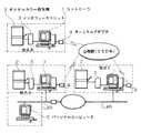
以下に、本発明の画像伝送システムにおける実施の形態を図に基づいて説明する。図1は本実施形態の画像伝送システムを説明する構成図である。すなわち、この画像伝送システムは、ワークステーションやパーソナルコンピュータ等から成るディスプレイを備えたコントローラ1と、画像の入出力を行うデジタルカラー複写機2と、コントローラ1とデジタルカラー複写機2とを接続するインタフェースユニット3と、コントローラ1を公衆網(ISDN)に接続するターミナルアダプタ4とを備えている。
【0013】
このような本実施形態の構成は、例えばA地点、B地点、C地点の各々に設けられている。なお、図1に示す例では、地点Aのコントローラ1が公衆網(ISDN)のみに接続され、地点Bのコントローラ1および地点Cのコントローラ1が各々公衆網(ISDN)とLANとに接続されているものとする。
【0014】
コントローラ1は、そのディスプレイに表示された内容に従いデジタルカラー複写機2による画像の入出力および入力した画像の伝送を制御する。
【0015】
また、デジタルカラー複写機2は、単独のカラー複写機として機能する他、コントローラ1の制御によって画像の入出力を行う。
【0016】
インタフェースユニット3は、デジタルカラー複写機2で入力した画像を蓄積したり、あるいは他の地点から送られてきた画像(プリント出力するための画像等)を蓄積したり、コントローラ1とデジタルカラー複写機2との間のデータ入出力を制御する。
【0017】
このインタフェースユニット3は、デジタルカラー複写機2で入力した画像やプリント出力するための画像の色空間変換や階調補正、フィルタリング処理などの画像処理機能を備えており、SCSIやセントロニクス等のインタフェースによってコントローラ1と接続されている。
【0018】
なお、図1においてはインタフェースユニット3を独立した構成として示しているが、コントローラ1に内蔵される拡張ボード構成として実現してもよい。
【0019】
また、ターミナルアダプタ4は、コントローラ1と公衆網(ISDN)とをつなぎ、64kbps/128kbpsでの画像伝送(送受信)を可能にするためのものである。
【0020】
このような構成において、コントローラ1は通信制御手段を備えており、LANとの接続が可能となっている。通信プロトコルとしては、例えばTCP/IPやApple Talk(アップル社)が利用できる。
【0021】
また、コントローラ1は所定のユーザインタフェースによって読み取り原稿の種類や解像度、圧縮率等を指定できるようになっている。さらに同様なユーザインタフェースによって画像送信の相手先を設定する宛先編集機能を備える。
【0022】
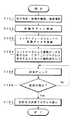
次に、本実施形態の画像伝送システムにおける動作を説明する。図2は画像伝送の流れを説明するフローチャートである。なお、この例では図1に示す地点Aから地点Bに画像を伝送するものとする。
【0023】
先ず、地点Aのコントローラ1のディスプレイに示されたユーザインタフェースによって、画像の宛先指定、原稿の種類、画質選択を行う(ステップS101)。宛先は予めコントローラ1に登録されており、必要に応じて編集することができる。
【0024】
表1は登録されている宛先の一覧を示す表である。すなわち、この一覧には名前に対応した宛先(ISDN番号やIPアドレス等)と回線種別とが登録されている。コントローラ1はこの宛先の編集機能を備えており、新たな宛先の追加や変更、削除を行うことができるようになっている。また、この宛先(ISDN番号やIPアドレス等)および回線種別を変更することで、通信プロトコルを変更できるようになっている。
【0025】
【表1】
宛先等を指定した後は、原稿のスキャンを開始する(ステップS102)。すなわち、図1に示すデジタルカラー複写機2に原稿をセットしてスキャンを開始し、画像の読み取りを行う。
【0027】
次いで、デジタルカラー複写機2で読み取った画像をインタフェースユニット3へ送り、格納する(ステップS103)。この格納された画像はコントローラ3で取り込まれ、そのディスプレイにプログレス表示される。また、この画像は所定の圧縮処理が施される(ステップS104)。
【0028】
次に、画像の送信チェックを行い(ステップS105)、送信可能か否かの判断を行う(ステップS106)。送信不可能な場合はステップS105へ戻って再度送信チェックを行う。また、送信可能な場合は画像の送信を行うとともに送信プログレスをコントローラ1のディスプレイに表示する(ステップS107)。
【0029】
これにより、図1の地点Aにおけるデジタルカラー複写機2で読み取った原稿の画像をコントローラ1の制御によって公衆網(ISDN)を介して地点Bのコントローラ1へ送ることができるようになる。
【0030】
図3〜図5は画像伝送におけるユーザインタフェースを説明する図である。すなわち、画像伝送を行う場合、先ず図3に示す画面表示S1が地点Aのコントローラ1のディスプレイ上に現れる。
【0031】
この画面表示S1にはFAX送信ボタンB1とファイル送信ボタンB2とが表示されている。ユーザは画面表示S1上のポインタ(図示せず)によって所望の送信ボタンを指定する。
【0032】
例えば、FAX送信ボタンB1を指定した場合には、次に図4に示す画面表示S2がディスプレイ上に現れる。ここでは、宛名帳のウインドウW1と、送信先のウインドウW2とが表示される。宛名帳のウインドウW1には、表1に示す登録された宛先の名前が表示される。
【0033】
ユーザは、この宛名帳のウインドウW1の中から送信の地点に対応した宛名を指定する。ここで、例えば「海老名CG(INS)」を指定すると、送信先のウインドウW2にその指定した宛名が表示される。
【0034】
送信先のウインドウW2に宛名が表示されると、画面表示S2には通知相手先名のウインドウW3が現れる。ここには、画像を送りたい相手の名前を入力する。つまり、ファクシミリ送信を行う際の宛名に対応する部分である。
【0035】
次に、ユーザは必要に応じて画質選択ボタンB3を選択して、読み取り画像の条件を指定する。例えば、原稿の種類、カラーか白黒か、圧縮モード、画質(高画質、標準、低画質等)、紙サイズ等を指定することができる。
【0036】
各種の指定が終わった後は、決定ボタンB4を選択する。これにより、次の図5に示す画面表示S3が現れる。ここでは、「原稿をセットして下さい」等のメッセージが表示され、これに従って原稿をデジタルカラー複写機2のプラテンまたは自動原稿送り機構にセットする。そして、送信ボタンB5を選択する。
【0037】
この送信ボタンB5を選択することにより、デジタルカラー複写機2にセットした原稿のスキャンが始まり、読み取った画像データをインタフェースユニット3のメモリに格納するようになる。なお、この格納の前に画像データは所望の色変換やフィルタリング処理が施される。
【0038】
また、この画像データの取り込みとともに、コントローラ1はそのディスプレイに読み取った画像の表示を行い読み取り状況を知らせるとともいに、画像データの圧縮処理を行う。圧縮された画像データは送信プールとして蓄積されることになる。
【0039】
そして、送信チェックを行った後、送信可能であれば送信プールされた画像データをターミナルアダプタ4を介して公衆網(ISDN)に接続された地点Bへ送られることになる。
【0040】
なお、画像の代わりに所定のファイルを送信する場合には、図3に示す表示画面S1においてファイル送信ボタンB2を選択する。送信先の選択は図4に示すものと同じである。その後は、図6に示す画面表示S4が現れ、そのファイル選択ウインドウW4によって送信対象のファイルを指定し、送信ボタンB6を選択する。ファイルの選択は複数でも可能である。これによって、地点Aから公衆網(ISDN)を介して地点Bに所定のファイルが送信されることになる。また、複数のファイルが選択された場合には、全てのファイルを一括送信できることになる。
【0041】
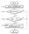
次に、本実施形態の画像伝送システムにおける画像受信の流れを図7のフローチャートに基づいて説明する。なお、ここでは図1に示す地点Aから送られた画像を地点Bで受信する場合の動作を説明する。
【0042】
先ず、地点Bのコントローラ1によって公衆網(ISDN)およびターミナルアダプタ4を介して送られてくる画像データを受信する(ステップS201)。この画像データは受信スプールホルダへ格納される。
【0043】
次に、配信先の該当登録者と一致すれば着信情報をその登録者へ送付する処理を行う(ステップS202)。つまり、受信側(ここでは、地点B)のコントローラ1には予め地点Bの画像伝送システムの利用者が登録されている。表2は登録ユーザ一覧の例を示す表である。
【0044】
【表2】
このように、画像の送信があった旨を通知する登録ユーザの名前と、その社内メールアドレス、TCP/IPのIPアドレス等が予め登録されている。また、コントローラ1には、この登録ユーザの追加、変更、削除等を行う編集機能が設けられている。
【0046】
地点Bのコントローラ1は、送られてきた画像データに含まれる受信情報(宛名、電話番号、着信通知相手、着信時間、枚数、ファイル名など)をもとに、その着信通知相手が登録されているか照合を行う。
【0047】
そして、登録されているユーザであれば、コントローラ1からLAN上のユーザ宛(そのユーザのパーソナルコンピュータ5(図1参照)など)に着信情報(画像等の伝送があった旨)の通知を行う。
【0048】
これによって、登録ユーザ(コンピュータ5)の場所と画像伝送システムとが離れた位置にあっても画像伝送のあったことを知ることができるようになる。
【0049】
次に、コントローラ1は受信した画像の受信ウインドウ処理または印刷処理を実行する(ステップS203)。この受信ウインドウ処理とは、受信した画像データを直ちに印刷しないでディスプレイに処理指示画面を出し、プレビュー表示、印刷後保管、保管、削除等の処理を受け付けるようにする処理である。この受信ウインドウ処理と印刷処理とは、モード設定によって決めることができる。
【0050】
次に、プリンタチェックおよび印刷プログレスを行う(ステップS204)。通常受信した画像データは圧縮されているので、コントローラ1内で伸長処理される。次いで、その画像データをコントローラ1からSCSI等で接続されているインタフェースユニット3へ送る(ステップS205)。
【0051】
そして、インタフェースユニット3において、この画像データの色空間変換やフィルタリング処理などを行い、デジタルカラー複写機2への出力データとして送信する(ステップS206)。これによって、デジタルカラー複写機2により受信画像をプリント出力できることになる(ステップS207)。
【0052】
図8は着信情報通知を説明するフローチャートである。すなわち、受信側のコントローラ1は、受信した画像データに含まれる送信元/宛先情報を格納した後(ステップS301)、配信先の指定があるか否かの判断を行う(ステップS302)。
【0053】
この配信先の指定とは、図4に示すユーザインタフェースの画面表示S2において通知相手先名のウインドウW3に入力した名前のことである。名前を入力した場合には、送信データのヘッダ部分にその名前のデータが含まれることになる。指定がない場合にはそのまま終了し、指定がある場合にはその指定が登録ユーザであるか否かを判断する(ステップS303)。
【0054】
登録ユーザでない場合にはそのまま終了し、登録ユーザである場合には登録ユーザのリソースに合わせて着信情報を配信する(ステップS304)。これによって、登録ユーザは、自分宛の画像が送られてきたことを自らが移動することなく知ることが可能となる。
【0055】
このような送信側のデジタルカラー複写機2による画像の取り込み、送信側のコントローラ1による画像の伝送、および受信側のコントローラ1による画像の受信、受信側のデジタルカラー複写機2による画像のプリント出力によって、ファクシミリ送信の要領でカラー画像の送受信を行うことが可能となる。
【0056】
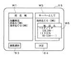
また、本実施形態の画像伝送システムでは、受信画像を転送することもできるようになっている。図9は画像転送を指定するユーザインタフェースを説明する図である。すなわち、画像を送る際に指定する相手先として、図4に示す画面表示に代えて図9に示す画面表示S5を行う。
【0057】
この画面表示S5には、宛名帳のウインドウW1と、サーバーを指定するウインドウW5とが現れている。つまり、画像の転送を行う場合には、送信先をサーバーとして指定しておき、そのサーバーとなった地点から画像データを転送先へ転送してもらうことになる。
【0058】
例えば、図1に示す地点Aから地点Bに画像を送り、地点Bから地点Cへ転送する場合、送信処理を行うユーザは図9に示す画面表示S5に基づき宛名帳のウインドウW1から地点Bに対応した宛名を選択する。これにより、選択した宛名(例えば、海老名CG(INS))がサーバーを指定するウインドウW5に表示されることになる。
【0059】
また、この宛名が表示されると、転送先を指定するウインドウW6が表示される。そして、このウインドウW6に転送先のIPアドレスやISDN番号を入力する。その後、必要に応じて画質選択ボタンB3を選択して画質の選択設定を行い、決定ボタンB4を選択する。
【0060】
これにより、その後の処理でデジタルカラー複写機2で読み取った画像を地点Aから公衆網(ISDN)を介して地点Bへ送り、地点BからLANまたは公衆網(ISDN)を介して地点Cへ転送できるようになる。
【0061】
なお、上記説明ではデジタルカラー複写機2で読み取った画像を転送する例を示したが、ファイルの転送を行う場合であっても同様である。
【0062】
また、上記いずれの例でも、送信先の回線がビジーの場合やデジタルカラー複写機2が使用中の場合には一旦送信処理やプリント処理を中止し、予め設定された時間毎に指定回数リトライするようにすればよい。
【0063】
【発明の効果】
以上説明したように、本発明の画像伝送システムによれば次のような効果がある。回線を介して外部から送られる画像を受信した場合に、画像が送られてきた旨の通知を着信通知先へ行うため、ユーザと画像伝送システムとが離れた位置にあっても画像伝送のあったことを知ることができるようになる。また、コントローラのディスプレイ表示にしたがい、所定の送信先を経由して画像を転送するための指定を容易に行うことができるようになる。これにより、システムを共有使用している場合であってもその利便性を大幅に向上させることが可能となる。
【図面の簡単な説明】
【図1】本実施形態の画像伝送システムを説明する構成図である。
【図2】画像伝送の流れを説明するフローチャートである。
【図3】画像伝送におけるユーザインタフェースを説明する図である。
【図4】画像伝送におけるユーザインタフェースを説明する図である。
【図5】画像伝送におけるユーザインタフェースを説明する図である。
【図6】ファイル選択時の画面表示を示す図である。
【図7】画像受信の流れを説明するフローチャートである。
【図8】着信情報通知を説明するフローチャートである。
【図9】画像転送指定時の画面表示を示す図である。
【符号の説明】
1…コントローラ、2…デジタルカラー複写機、3…インタフェースユニット、4…ターミナルアダプタ、5…パーソナルコンピュータ[0001]
BACKGROUND OF THE INVENTION
The present invention relates to an image transmission system for transmitting an image captured by an image input / output device such as a digital color copying machine via a predetermined line.
[0002]
[Prior art]
In recent years, the use of communication networks such as the Internet has increased due to the spread of computers and local and wide area networks. Attempts have also been made to connect various peripheral devices to a LAN (Local Area Network).
[0003]
For example, there is a product that provides a facsimile apparatus that directly interfaces a printer to a network and a scanner that directly interfaces to the network, and provides the network interface directly to the facsimile apparatus.
[0004]
Under such circumstances, Japanese Patent Application Laid-Open No. 9-91102 discloses a system that generates an appropriate message based on the completion status or interruption status of a job in a printer and notifies the user.
[0005]
Japanese Laid-Open Patent Publication No. 9-18639 discloses a technique for allowing a network user to separately use a scanning function and a printing function of a copying machine.
[0006]
Further, Japanese Patent Laid-Open No. 9-163062 discloses a facsimile machine with a terminal device that can easily give an instruction such as a destination facsimile number at the time of facsimile transmission.
[0007]
[Problems to be solved by the invention]
However, in the conventional image transmission by the facsimile apparatus, the transmission-side facsimile apparatus and the reception-side facsimile apparatus are connected point-to-point via a line, so it is determined whether the received image has been output. There is a problem that it cannot be confirmed without going to the place.
[0008]
In general, a device such as a facsimile machine or a copier is shared by about one or two devices for each department, and there is a problem in convenience of use in individual units. Moreover, a facsimile machine using a public line cannot transmit a color image. When transmitting a color image from the outside, the computer is connected to a network such as a LAN by a predetermined protocol, and then the image is transmitted. As described above, there is a problem that it cannot be performed by a simple procedure such as transmission by a facsimile apparatus.
[0009]
Furthermore, it is considered that a copying machine or the like is directly connected to a network for use, but the copying machine itself needs to have a function necessary for network connection, resulting in a complicated system configuration.
[0010]
[Means for Solving the Problems]
The present invention is an image transmission system designed to solve such problems. In other words, the image transmission system of the present invention includes a controller that includes a display and is connected to a predetermined line, andan image input / output unitthat is connected to thecontroller. When the image sent from the outside via the line is received, the image is sent based on the destination notification destination information sent together with the received image. Notification to the other party of the incoming call notification.
[0011]
In the present invention, a controller composed of a personal computer or the like and an image input / output means composed of a copying machine or the like are connected, so that the controller controls the image input / output means to input an image, and a predetermined line is connected. The image can be transmitted through the network. That is, an image can be transmitted through the controller even if the image input / output means is not connected to the line.In addition, when the controller receives an image sent from the outside via a line, the user and the image transmission system are located at a distance from each other in order to notify the other party of the incoming call notification that the image has been sent. Will also be able to know that there was image transmission.
[0012]
DETAILED DESCRIPTION OF THE INVENTION
Embodiments of the image transmission system according to the present invention will be described below with reference to the drawings. FIG. 1 is a configuration diagram illustrating an image transmission system according to the present embodiment. That is, this image transmission system includes a controller 1 provided with a display such as a workstation or a personal computer, a digital
[0013]
Such a configuration of the present embodiment is provided at each of points A, B, and C, for example. In the example shown in FIG. 1, the controller 1 at the point A is connected only to the public network (ISDN), and the controller 1 at the point B and the controller 1 at the point C are respectively connected to the public network (ISDN) and the LAN. It shall be.
[0014]
The controller 1 controls the input / output of an image and the transmission of the input image by the digital
[0015]
The digital
[0016]
The
[0017]
The
[0018]
Although the
[0019]
The
[0020]
In such a configuration, the controller 1 includes communication control means, and can be connected to a LAN. For example, TCP / IP or Apple Talk (Apple) can be used as the communication protocol.
[0021]
Further, the controller 1 can designate the type, resolution, compression rate, etc. of the read document by a predetermined user interface. Furthermore, a destination editing function for setting a destination of image transmission by a similar user interface is provided.
[0022]
Next, the operation in the image transmission system of this embodiment will be described. FIG. 2 is a flowchart for explaining the flow of image transmission. In this example, it is assumed that an image is transmitted from point A to point B shown in FIG.
[0023]
First, an image destination designation, document type, and image quality are selected by the user interface shown on the display of the controller 1 at the point A (step S101). The destination is registered in advance in the controller 1, and can be edited as necessary.
[0024]
Table 1 is a table showing a list of registered destinations. That is, in this list, destinations (ISDN numbers, IP addresses, etc.) corresponding to names and line types are registered. The controller 1 has this address editing function, and can add, change, and delete new addresses. In addition, the communication protocol can be changed by changing the destination (ISDN number, IP address, etc.) and the line type.
[0025]
[Table 1]
After designating the destination or the like, scanning of the document is started (step S102). That is, a document is set on the digital
[0027]
Next, the image read by the digital
[0028]
Next, an image transmission check is performed (step S105), and it is determined whether transmission is possible (step S106). If transmission is not possible, the process returns to step S105 to check transmission again. If transmission is possible, the image is transmitted and transmission progress is displayed on the display of the controller 1 (step S107).
[0029]
Thereby, the image of the original read by the digital
[0030]
3 to 5 are diagrams illustrating a user interface in image transmission. That is, when image transmission is performed, a screen display S1 shown in FIG. 3 first appears on the display of the controller 1 at the point A.
[0031]
On this screen display S1, a FAX transmission button B1 and a file transmission button B2 are displayed. The user designates a desired transmission button by a pointer (not shown) on the screen display S1.
[0032]
For example, when the FAX transmission button B1 is designated, a screen display S2 shown in FIG. 4 appears on the display. Here, an address book window W1 and a destination window W2 are displayed. The registered address name shown in Table 1 is displayed in the address book window W1.
[0033]
The user designates an address corresponding to the point of transmission from the address book window W1. For example, when “Ebin name CG (INS)” is designated, the designated address is displayed in the transmission destination window W2.
[0034]
When the address is displayed in the destination window W2, the notification destination name window W3 appears on the screen display S2. Enter the name of the person you want to send the image to. That is, it is a part corresponding to the address when performing facsimile transmission.
[0035]
Next, the user selects the image quality selection button B3 as necessary, and specifies the conditions of the read image. For example, the type of document, color or black and white, compression mode, image quality (high image quality, standard, low image quality, etc.), paper size, etc. can be specified.
[0036]
After the various designations are finished, the determination button B4 is selected. As a result, the following screen display S3 shown in FIG. 5 appears. Here, a message such as “Please set the document” is displayed, and the document is set on the platen or automatic document feeding mechanism of the digital
[0037]
By selecting the transmission button B5, scanning of the original set on the digital
[0038]
At the same time as the capture of the image data, the controller 1 displays the read image on the display to notify the reading status and performs the compression processing of the image data. The compressed image data is stored as a transmission pool.
[0039]
After the transmission check, if transmission is possible, the transmission pooled image data is sent via the
[0040]
When a predetermined file is transmitted instead of an image, the file transmission button B2 is selected on the display screen S1 shown in FIG. The selection of the transmission destination is the same as that shown in FIG. Thereafter, a screen display S4 shown in FIG. 6 appears, and a file to be transmitted is designated by the file selection window W4 and the transmission button B6 is selected. Multiple files can be selected. As a result, a predetermined file is transmitted from the point A to the point B via the public network (ISDN). When a plurality of files are selected, all the files can be transmitted at once.
[0041]
Next, the flow of image reception in the image transmission system of this embodiment will be described based on the flowchart of FIG. Here, the operation when an image sent from the point A shown in FIG.
[0042]
First, the image data sent via the public network (ISDN) and the
[0043]
Next, if it matches the corresponding registrant at the delivery destination, a process of sending incoming information to the registrant is performed (step S202). That is, the user of the image transmission system at the point B is registered in advance in the controller 1 on the receiving side (here, the point B). Table 2 is a table showing an example of a registered user list.
[0044]
[Table 2]
As described above, the name of the registered user who notifies that the image has been transmitted, the in-house mail address, the IP address of TCP / IP, and the like are registered in advance. Further, the controller 1 is provided with an editing function for adding, changing, and deleting the registered user.
[0046]
The controller 1 at point B registers the incoming call notification partner based on the reception information (address, phone number, incoming call notification partner, incoming call time, number of copies, file name, etc.) included in the transmitted image data. Check whether or not.
[0047]
If the user is a registered user, the controller 1 notifies the user on the LAN (the user's personal computer 5 (see FIG. 1), etc.) of the incoming information (the fact that an image or the like has been transmitted). .
[0048]
This makes it possible to know that image transmission has occurred even if the location of the registered user (computer 5) and the image transmission system are separated from each other.
[0049]
Next, the controller 1 executes reception window processing or printing processing for the received image (step S203). The reception window process is a process for displaying a process instruction screen on the display without printing the received image data immediately and accepting processes such as preview display, storage after printing, storage, and deletion. The reception window process and the printing process can be determined by mode setting.
[0050]
Next, printer check and print progress are performed (step S204). Since normally received image data is compressed, it is decompressed in the controller 1. Next, the image data is sent from the controller 1 to the
[0051]
Then, the
[0052]
FIG. 8 is a flowchart for explaining notification of incoming information. That is, the receiving-side controller 1 stores the transmission source / destination information included in the received image data (step S301), and then determines whether or not a distribution destination is designated (step S302).
[0053]
The designation of the distribution destination is a name input in the notification partner name window W3 in the screen display S2 of the user interface shown in FIG. When a name is input, the data of that name is included in the header portion of the transmission data. If there is no designation, the processing ends as it is, and if there is designation, it is determined whether or not the designation is a registered user (step S303).
[0054]
If the user is not a registered user, the process is terminated. If the user is a registered user, the incoming call information is distributed according to the resource of the registered user (step S304). As a result, the registered user can know that the image addressed to himself / herself has been sent without moving.
[0055]
Capture of an image by the
[0056]
In the image transmission system of this embodiment, a received image can also be transferred. FIG. 9 is a diagram illustrating a user interface for designating image transfer. That is, the screen display S5 shown in FIG. 9 is performed instead of the screen display shown in FIG. 4 as the destination to be specified when sending the image.
[0057]
In this screen display S5, an address book window W1 and a window W5 for designating a server appear. In other words, when transferring an image, the destination is designated as a server, and the image data is transferred to the transfer destination from the point where the server becomes the server.
[0058]
For example, when an image is sent from point A to point B and transferred from point B to point C shown in FIG. Select the corresponding address. As a result, the selected address (for example, Ebina CG (INS)) is displayed in the window W5 for designating the server.
[0059]
When this address is displayed, a window W6 for designating a transfer destination is displayed. Then, the IP address and ISDN number of the transfer destination are entered in this window W6. Thereafter, if necessary, the image quality selection button B3 is selected to perform image quality selection setting, and the decision button B4 is selected.
[0060]
As a result, an image read by the digital
[0061]
In the above description, an example in which an image read by the digital
[0062]
In any of the above examples, when the transmission destination line is busy or the digital
[0063]
【The invention's effect】
As described above, the image transmission system of the present invention has the following effects.When an image sent from the outside via a line is received, a notification that the image has been sent is sent to the incoming call notification destination. You will be able to know that. Further, according to the display on the controller, it is possible to easily specify for transferring an image via a predetermined transmission destination. Thereby, even when the system is shared and used, the convenience can be greatly improved.
[Brief description of the drawings]
FIG. 1 is a configuration diagram illustrating an image transmission system according to an embodiment.
FIG. 2 is a flowchart illustrating a flow of image transmission.
FIG. 3 is a diagram illustrating a user interface in image transmission.
FIG. 4 is a diagram illustrating a user interface in image transmission.
FIG. 5 is a diagram illustrating a user interface in image transmission.
FIG. 6 is a diagram showing a screen display when a file is selected.
FIG. 7 is a flowchart illustrating a flow of image reception.
FIG. 8 is a flowchart illustrating notification of incoming information.
FIG. 9 is a diagram showing a screen display when image transfer is designated.
[Explanation of symbols]
DESCRIPTION OF SYMBOLS 1 ... Controller, 2 ... Digital color copying machine, 3 ... Interface unit, 4 ... Terminal adapter, 5 ... Personal computer
Claims (2)
Translated fromJapanese前記コントローラと接続される画像入出力手段とを備えており、
前記コントローラは、前記画像入出力手段での画像の入出力および前記回線を介した画像伝送を制御するとともに、前記回線を介して外部から送られる画像を受信した場合、この受信した画像とともに送られた着信通知相手先情報に基づき、画像が送られてきた旨の通知を着信通知相手先へ行う
ことを特徴とする画像伝送システム。A controller having a display and connected to a predetermined line;
Image input / output meansconnected to the controller;
The controller controls input / output of an image in the image input / output means and image transmission via the line, and when an image sent from the outside via the line is received, the controller sends the image together with the received image. An image transmission system thatperforms notification to an incoming call notification partner that an image has been sent based on the incoming call notification partner information .
前記コントローラと接続される画像入出力手段とを備えており、Image input / output means connected to the controller;
前記コントローラによって前記画像入出力手段での画像の入出力および前記回線を介した画像伝送を制御する画像伝送システムであって、An image transmission system for controlling image input / output at the image input / output means and image transmission via the line by the controller,
前記コントローラは、前記画像入出力手段により入力された画像の伝送先および転送先の指定を行うための表示を前記ディスプレイに表示させるユーザインタフェース手段を備えているThe controller includes user interface means for displaying on the display a display for designating a transmission destination and a transfer destination of an image input by the image input / output means.
ことを特徴とする画像伝送システム。An image transmission system characterized by that.
Priority Applications (1)
| Application Number | Priority Date | Filing Date | Title |
|---|---|---|---|
| JP35657297AJP3608360B2 (en) | 1997-12-25 | 1997-12-25 | Image transmission system |
Applications Claiming Priority (1)
| Application Number | Priority Date | Filing Date | Title |
|---|---|---|---|
| JP35657297AJP3608360B2 (en) | 1997-12-25 | 1997-12-25 | Image transmission system |
Publications (2)
| Publication Number | Publication Date |
|---|---|
| JPH11191818A JPH11191818A (en) | 1999-07-13 |
| JP3608360B2true JP3608360B2 (en) | 2005-01-12 |
Family
ID=18449700
Family Applications (1)
| Application Number | Title | Priority Date | Filing Date |
|---|---|---|---|
| JP35657297AExpired - Fee RelatedJP3608360B2 (en) | 1997-12-25 | 1997-12-25 | Image transmission system |
Country Status (1)
| Country | Link |
|---|---|
| JP (1) | JP3608360B2 (en) |
Families Citing this family (1)
| Publication number | Priority date | Publication date | Assignee | Title |
|---|---|---|---|---|
| JP3525842B2 (en)* | 2000-02-01 | 2004-05-10 | 日本電気株式会社 | Network scanner device and recording medium recording program |
- 1997
- 1997-12-25JPJP35657297Apatent/JP3608360B2/ennot_activeExpired - Fee Related
Also Published As
| Publication number | Publication date |
|---|---|
| JPH11191818A (en) | 1999-07-13 |
Similar Documents
| Publication | Publication Date | Title |
|---|---|---|
| US8830536B2 (en) | Image processing device, image processing method and remote-scan image processing system using the same | |
| CN100477716C (en) | Data transmission/reception system for notifying user that image data has been transmitted | |
| US7289245B2 (en) | Color facsimile device capable of transmitting color image information represented in appropriate color space through multiple communication channels | |
| JP2002288097A (en) | Image processing device, image transmission method and program | |
| JPH11112778A (en) | Facsimile machine with e-mail function | |
| JP3608360B2 (en) | Image transmission system | |
| JP3675624B2 (en) | Network scanner | |
| JPH098983A (en) | Image communication device, image processing device, and control method thereof | |
| JPH1155486A (en) | Facsimile machine | |
| CN110602342B (en) | Fax machine transmission control method and system, computer equipment and readable storage medium | |
| JPH10271263A (en) | Peripheral device management device and control method therefor | |
| JP2002010007A (en) | Network facsimile equipment and method for selecting line | |
| JP2005528053A (en) | System and method for generating and transferring image data | |
| JP2000032184A (en) | Image processing device | |
| JP3369252B2 (en) | Communication device and communication control method | |
| JP4389408B2 (en) | Communication terminal device | |
| JPH1041937A (en) | Multimedia information communication terminal device and multimedia information communication system | |
| JP2001007842A (en) | Communication equipment | |
| JP2005191672A (en) | Facsimile machine | |
| JP3395709B2 (en) | Facsimile machine | |
| JPH09233291A (en) | Image processing system | |
| JP2001005749A (en) | Communication equipment | |
| JP2000307793A (en) | Internet facsimile machine | |
| JP2000216928A (en) | Network facsimile equipment | |
| JPH0795313A (en) | Fax machine |
Legal Events
| Date | Code | Title | Description |
|---|---|---|---|
| A977 | Report on retrieval | Free format text:JAPANESE INTERMEDIATE CODE: A971007 Effective date:20040220 | |
| A131 | Notification of reasons for refusal | Free format text:JAPANESE INTERMEDIATE CODE: A131 Effective date:20040224 | |
| A521 | Written amendment | Free format text:JAPANESE INTERMEDIATE CODE: A523 Effective date:20040426 | |
| TRDD | Decision of grant or rejection written | ||
| A01 | Written decision to grant a patent or to grant a registration (utility model) | Free format text:JAPANESE INTERMEDIATE CODE: A01 Effective date:20040921 | |
| A61 | First payment of annual fees (during grant procedure) | Free format text:JAPANESE INTERMEDIATE CODE: A61 Effective date:20041004 | |
| R150 | Certificate of patent or registration of utility model | Free format text:JAPANESE INTERMEDIATE CODE: R150 | |
| FPAY | Renewal fee payment (event date is renewal date of database) | Free format text:PAYMENT UNTIL: 20071022 Year of fee payment:3 | |
| FPAY | Renewal fee payment (event date is renewal date of database) | Free format text:PAYMENT UNTIL: 20081022 Year of fee payment:4 | |
| FPAY | Renewal fee payment (event date is renewal date of database) | Free format text:PAYMENT UNTIL: 20091022 Year of fee payment:5 | |
| FPAY | Renewal fee payment (event date is renewal date of database) | Free format text:PAYMENT UNTIL: 20101022 Year of fee payment:6 | |
| FPAY | Renewal fee payment (event date is renewal date of database) | Free format text:PAYMENT UNTIL: 20111022 Year of fee payment:7 | |
| FPAY | Renewal fee payment (event date is renewal date of database) | Free format text:PAYMENT UNTIL: 20121022 Year of fee payment:8 | |
| FPAY | Renewal fee payment (event date is renewal date of database) | Free format text:PAYMENT UNTIL: 20121022 Year of fee payment:8 | |
| FPAY | Renewal fee payment (event date is renewal date of database) | Free format text:PAYMENT UNTIL: 20131022 Year of fee payment:9 | |
| LAPS | Cancellation because of no payment of annual fees |