JP3607854B2 - Base station apparatus, mobile station apparatus, and transmission power control method - Google Patents
Base station apparatus, mobile station apparatus, and transmission power control methodDownload PDFInfo
- Publication number
- JP3607854B2 JP3607854B2JP2000157166AJP2000157166AJP3607854B2JP 3607854 B2JP3607854 B2JP 3607854B2JP 2000157166 AJP2000157166 AJP 2000157166AJP 2000157166 AJP2000157166 AJP 2000157166AJP 3607854 B2JP3607854 B2JP 3607854B2
- Authority
- JP
- Japan
- Prior art keywords
- interference
- station apparatus
- mobile station
- station
- base station
- Prior art date
- Legal status (The legal status is an assumption and is not a legal conclusion. Google has not performed a legal analysis and makes no representation as to the accuracy of the status listed.)
- Expired - Fee Related
Links
Images


Classifications
- H—ELECTRICITY
- H04—ELECTRIC COMMUNICATION TECHNIQUE
- H04B—TRANSMISSION
- H04B1/00—Details of transmission systems, not covered by a single one of groups H04B3/00 - H04B13/00; Details of transmission systems not characterised by the medium used for transmission
- H04B1/69—Spread spectrum techniques
- H04B1/707—Spread spectrum techniques using direct sequence modulation
- H04B1/7097—Interference-related aspects
- H04B1/7103—Interference-related aspects the interference being multiple access interference
- H—ELECTRICITY
- H04—ELECTRIC COMMUNICATION TECHNIQUE
- H04W—WIRELESS COMMUNICATION NETWORKS
- H04W52/00—Power management, e.g. Transmission Power Control [TPC] or power classes
- H04W52/04—Transmission power control [TPC]
- H04W52/18—TPC being performed according to specific parameters
- H04W52/24—TPC being performed according to specific parameters using SIR [Signal to Interference Ratio] or other wireless path parameters
- H04W52/243—TPC being performed according to specific parameters using SIR [Signal to Interference Ratio] or other wireless path parameters taking into account interferences
- H—ELECTRICITY
- H04—ELECTRIC COMMUNICATION TECHNIQUE
- H04B—TRANSMISSION
- H04B2201/00—Indexing scheme relating to details of transmission systems not covered by a single group of H04B3/00 - H04B13/00
- H04B2201/69—Orthogonal indexing scheme relating to spread spectrum techniques in general
- H04B2201/707—Orthogonal indexing scheme relating to spread spectrum techniques in general relating to direct sequence modulation
- H04B2201/7097—Direct sequence modulation interference
- H04B2201/709709—Methods of preventing interference
- H—ELECTRICITY
- H04—ELECTRIC COMMUNICATION TECHNIQUE
- H04W—WIRELESS COMMUNICATION NETWORKS
- H04W52/00—Power management, e.g. Transmission Power Control [TPC] or power classes
- H04W52/04—Transmission power control [TPC]
- H04W52/06—TPC algorithms
- H04W52/14—Separate analysis of uplink or downlink
- H04W52/146—Uplink power control
- H—ELECTRICITY
- H04—ELECTRIC COMMUNICATION TECHNIQUE
- H04W—WIRELESS COMMUNICATION NETWORKS
- H04W52/00—Power management, e.g. Transmission Power Control [TPC] or power classes
- H04W52/04—Transmission power control [TPC]
- H04W52/18—TPC being performed according to specific parameters
- H04W52/26—TPC being performed according to specific parameters using transmission rate or quality of service QoS [Quality of Service]
- H04W52/267—TPC being performed according to specific parameters using transmission rate or quality of service QoS [Quality of Service] taking into account the information rate
Landscapes
- Engineering & Computer Science (AREA)
- Computer Networks & Wireless Communication (AREA)
- Signal Processing (AREA)
- Mobile Radio Communication Systems (AREA)
- Transmitters (AREA)
Description
Translated fromJapanese【0001】
【発明の属する技術分野】
本発明は、基地局装置、移動局装置および送信電力制御方法に関する。
【0002】
【従来の技術】
CDMA方式を用いた移動体通信システムでは、いわゆる遠近問題を解決するために、送信電力制御が行われる。また、送信電力制御には、大別してオープンループ型の送信電力制御とクローズドループ型の送信電力制御がある。
【0003】
このうちクローズドループ型の送信電力制御が下り回線(基地局から移動局へ向かう回線)に適用された場合には、移動局および基地局は以下のように動作する。
【0004】
すなわち、移動局が、受信信号の品質を示すSIR(Signal to Interference Ratio;希望波対干渉波電力比)を測定し、その測定したSIRと目標とするSIRとを比較する。そして、移動局は、測定したSIRが目標とするSIRよりも大きい場合は、送信電力を下げる命令を基地局へ送り、測定したSIRが目標とするSIR以下の場合は、送信電力を上げる命令を基地局へ送る。基地局は、この命令に従って送信電力を増減させる。
【0005】
このように、下り回線で行われるクローズドループ型の送信電力制御では、移動局は、自局が受けている干渉量に基づいて基地局へ送信電力の上げ下げを指示する。
【0006】
【発明が解決しようとする課題】
ここで、CDMA方式では同一周波数帯域で同一時刻に基地局が複数の移動局と通信を行うため、ある移動局に対する送信電力の増加は、その移動局以外の他の移動局に対する干渉量を増加させる原因となる。また、干渉量が増加した移動局は、受信品質を保つために送信電力を上げる命令を基地局へ送る。そして、基地局が、命令を送信した移動局に対する送信電力を増加させると、その移動局以外の他の移動局に対する干渉量が増加する。
【0007】
このような一連の動作が繰り返されると、すべての移動局に対する送信電力が徐々に大きくなり、それに伴ない他の移動局に対する干渉量も徐々に増加する。このように移動局相互に与える干渉量が徐々に増加すると、いずれ相互に与える干渉量が許容できないほど増加する可能性がある。その結果、基地局が自セル内に収容できる移動局数が著しく減少していく。すなわち、システム容量が著しく減少してしまう。
【0008】
本発明はかかる点に鑑みてなされたものであり、システム容量を減少させないように適切な送信電力制御を行うことができる基地局装置、移動局装置および送信電力制御方法を提供することを目的とする。
【0009】
【課題を解決するための手段】
本発明の基地局装置は、通信中にある複数の移動局のうち他の移動局に対して干渉を与える移動局である干渉局を示す干渉局情報を受信する受信手段と、前記複数の移動局の各々へ信号を送信する送信手段と、前記干渉局情報に従って、前記送信手段から送信される信号のうち前記干渉局へ送信される信号の送信電力を減少させる制御手段と、を具備する構成を採る。
【0010】
この構成によれば、干渉を受けている移動局装置に対する送信信号の送信電力を増加させて干渉量を相対的に小さくするのではなく、干渉の原因となっている移動局装置に対する送信信号の送信電力を減少させることにより干渉量を直接的に減少させるため、移動局装置相互に与える干渉量が増加することを防止することができる。
【0012】
本発明の基地局装置は、前記複数の移動局の各々に割り当てられている拡散コードを示す情報を前記複数の移動局に報知する報知手段をさらに具備する構成を採る。
【0013】
この構成によれば、基地局装置が移動局装置を示す情報(例えば、拡散コード)を各移動局装置に報知するので、各移動局装置では調査対象となる他局を絞り込むことができるので、干渉局の検出に要する時間を短くすることができる。
【0015】
本発明の基地局装置は、前記制御手段が、複数の移動局に対して干渉を与える前記干渉局へ送信される信号の送信電力を減少させる構成を採る。
【0016】
この構成によれば、複数の移動局装置に干渉を与えている干渉局をシステム容量の減少に大きな影響を与えている移動局装置として特定し、その特定した移動局装置に対する送信電力を減少させるため、システム容量の減少に大きな影響を与えている干渉ほど優先的に除去することができる。
【0017】
本発明の基地局装置は、前記制御手段が、同一の移動局から受信された前記干渉局情報で複数回示された前記干渉局へ送信される信号の送信電力を減少させる構成を採る。
【0018】
この構成によれば、各移動局装置において複数回検出された干渉局を送信電力を減少させるべき移動局装置として特定するため、より確実な情報に基づいて送信電力を減少させるべき移動局装置を特定することができる。
【0019】
本発明の基地局装置は、前記制御手段が、前記干渉局へ送信される信号の送信電力を減少させるとともに、前記干渉局へ送信される信号の伝送レートを低下させる構成を採る。
【0020】
本発明の基地局装置は、前記制御手段が、前記干渉局へ送信される信号の拡散率を上げることにより前記伝送レートを低下させる構成を採る。
【0021】
本発明の基地局装置は、前記制御手段が、前記干渉局へ送信される信号の変調多値数を小さくすることにより前記伝送レートを低下させる構成を採る。
【0022】
これらの構成によれば、送信電力の減少に応じて伝送レートを低下させるため、通信品質を維持することができる。
【0023】
本発明の基地局装置は、前記制御手段が、前記干渉局へ送信される信号を間欠的に送信させることにより前記伝送レートを低下させる構成を採る。
【0024】
この構成によれば、送信信号に間欠部分が生じるので、平均的に見て干渉量を減少することができる。
【0025】
本発明の移動局装置は、自局に対して干渉を与える他の移動局である干渉局を検出する検出手段と、検出された干渉局を示す干渉局情報を基地局へ送信する送信手段と、を具備する構成を採る。
【0026】
この構成によれば、干渉を受けている移動局装置に対する送信信号の送信電力を増加させて干渉量を相対的に小さくするのではなく、干渉の原因となっている移動局装置に対する送信信号の送信電力を減少させることにより干渉量を直接的に減少させるため、移動局装置相互に与える干渉量が増加することを防止することができる。
【0029】
本発明の移動局装置は、前記基地局と通信中にある他の移動局に割り当てられている拡散コードで受信信号を逆拡散して前記拡散コードと前記受信信号との相関値を得る逆拡散手段、をさらに具備し、前記検出手段は、前記相関値がしきい値以上となる拡散コードが割り当てられている他の移動局を前記干渉局として検出する構成を採る。
【0030】
この構成によれば、干渉を受けている移動局装置に対する送信信号の送信電力を増加させて干渉量を相対的に小さくするのではなく、干渉の原因となっている移動局装置に対する送信信号の送信電力を減少させることにより干渉量を直接的に減少させるため、移動局装置相互に与える干渉量が増加することを防止することができる。
【0031】
本発明の送信電力制御方法は、複数の移動局と、前記複数の移動局と同時に通信する基地局と、を有する移動体通信システムにおいて使用される送信電力制御方法であって、前記複数の移動局の各々が、自局に対して干渉を与える他の移動局である干渉局を検出し、検出した干渉局を示す干渉局情報を前記基地局へ送信し、
前記基地局が、前記干渉局情報を受信し、前記干渉局情報に従って、前記基地局から前記複数の移動局の各々へ送信する信号のうち前記干渉局へ送信する信号の送信電力を減少させるようにした。
【0032】
この方法によれば、干渉を受けている移動局装置に対する送信信号の送信電力を増加させて干渉量を相対的に小さくするのではなく、干渉の原因となっている移動局装置に対する送信信号の送信電力を減少させることにより干渉量を直接的に減少させるため、移動局装置相互に与える干渉量が増加することを防止することができる。
【0035】
【発明の実施の形態】
本発明者は、所望の受信品質を得るには、移動局が干渉を受けている場合に、希望信号の送信電力を増加させる方法の他にも、干渉信号の送信電力を減少させる方法もあることに着目し、干渉の原因となっている移動局に対する信号の送信電力を減少させることにより、各移動局において所望の受信品質が得ることができるとともに、移動局相互に与える干渉量を小さくしてシステム容量の減少を防止できることを見出し、本発明をするに至った。
【0036】
すなわち、本発明の骨子は、干渉を受けている移動局に対する信号の送信電力を増加させることにより干渉量を相対的に小さくするのではなく、干渉の原因となっている移動局に対する信号の送信電力を減少させることにより干渉量を直接的に減少させることである。
【0037】
以下、本発明の実施の形態について、図面を参照して説明する。
(実施の形態1)
図1は、本発明の実施の形態1に係る基地局装置と本発明の実施の形態1に係る移動局装置とが通信を行う無線通信システムの概念図である。図1において、基地局装置101は、移動局装置A102および移動局装置B103と通信中である。
【0038】
また、移動局装置A102には拡散コードAが割り当てられ、移動局装置B103には拡散コードBが割り当てられている。すなわち、基地局装置101と移動局装置A102との間で送受信されるデータは拡散コードAで拡散されており、基地局装置101と移動局装置B103との間で送受信されるデータは拡散コードBで拡散されている。
【0039】
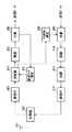
次いで、基地局装置101の構成について説明する。図2は、本発明の実施の形態1に係る基地局装置の構成を示す要部ブロック図である。なお、基地局装置101は、多重部202〜送信電力調節部205の送信系統および逆拡散部210〜分離部212の受信系統を、自局のセル内に収容可能な移動局装置数分だけ具備するが、ここでは説明の便宜上、それぞれ一系統のみ示すものとする。
【0040】
図2において、拡散コード報知部201は、現在通信中にある移動局装置に割り当てられている拡散コードを示す情報を各移動局装置へ報知する。多重部202は、拡散コードを示す情報を送信データに多重する。変調部203は、送信データに所定の変調処理を施す。拡散部204は、送信データを各移動局装置に割り当てられている拡散コードで拡散する。送信電力調節部205は、送信データの送信電力を調節する。送信RF部206は、送信データに対して周波数変換等の所定の無線処理を施す。共用器207は、アンテナ208を介して送受信される信号を送信と受信とに分離する。
【0041】
受信RF部209は、受信信号に対して周波数変換等の所定の無線処理を施す。逆拡散部210は、受信信号を各移動局装置に割り当てられている拡散コードで逆拡散する。復調部211は、受信信号に対して所定の復調処理を施す。分離部212は、復調された信号を、受信データと他の移動局装置に干渉を与える原因となっている移動局装置(以下、「干渉局」という。)を示す情報(以下、「干渉局情報」という。)とに分離する。制御部213は、干渉局への送信データの送信電力と伝送レートを制御する。
【0042】
次いで、移動局装置A102および移動局装置B103の構成について説明する。図3は、本発明の実施の形態1に係る移動局装置の構成を示す要部ブロック図である。なお、移動局装置A102および移動局装置B103は、同一の構成となる。
【0043】
図3において、共用器302は、アンテナ301を介して送受信される信号を送信と受信とに分離する。受信RF部303は、受信信号に対して周波数変換等の所定の無線処理を施す。逆拡散部304は、受信信号を自局に割り当てられている拡散コードおよび現在基地局装置と通信中である他の移動局装置に割り当てられている拡散コード(以下、「他局の拡散コード」という。)で逆拡散する。復調部305は、受信信号に対して所定の復調処理を施す。分離部306は、復調された信号を、受信データと他局の拡散コードを示す情報とに分離する。拡散コード指定部307は、逆拡散部304に対して他局の拡散コードを指定する。
【0044】
干渉局検出部308は、逆拡散結果より、自局に対して干渉を与える原因となっている他の移動局装置(つまり、干渉局)を検出する。多重部309は、干渉局情報を送信データに多重する。変調部310は、送信データに所定の変調処理を施す。拡散部311は、送信データを自局に割り当てられている拡散コードで拡散する。送信RF部312は、送信データに対して周波数変換等の所定の無線処理を施す。
【0045】
次いで上記構成を有する基地局装置および移動局装置の動作について説明する。まず、図2に示す基地局装置101において、拡散コード報知部201が、拡散コードAを示す情報および拡散コードBを示す情報を多重部202へ出力する。すなわち、拡散コード報知部201は、各移動局装置が干渉局として調査すべき移動局装置を示す情報を、各移動局装置へ報知する。換言すれば、拡散コード報知部201は、各移動局装置が自局にとっての干渉局となる可能性のある移動局装置を示す情報を、各移動局装置へ報知する。このように、基地局装置101が移動局装置を示す情報(ここでは、拡散コード)を各移動局装置に報知するので、各移動局装置では調査対象となる他局を絞り込むことができるので、干渉局の検出に要する時間を短くすることができる。
【0046】
多重部202では、送信データに拡散コードAを示す情報および拡散コードBを示す情報が多重され、多重後のデータが変調部203へ出力される。
【0047】
拡散コードAを示す情報および拡散コードBを示す情報が多重されたデータは、変調部203で所定の変調処理を施され、拡散部204で拡散される。このとき、移動局装置A102宛ての送信データは拡散コードAで拡散され、移動局装置B103宛ての送信データは拡散コードBで拡散される。そして、拡散後の送信データは、送信電力調節部205で送信電力が調節される。送信電力の調節方法については後述する。
【0048】
送信電力を調節された送信データは、送信RF部206で所定の無線処理を施された後、共用器207およびアンテナ208を介して各移動局装置へ送信される。
【0049】
次いで、図3に示す移動局装置A102および移動局装置B103において、アンテナ301および共用器302を介して受信された信号は、受信RF部303で所定の無線処理が施され、逆拡散部304へ出力される。
【0050】
逆拡散部304では、受信信号がまず自局に割り当てられている拡散コードで逆拡散される。すなわち、移動局装置A102では拡散コードAで受信信号が逆拡散され、移動局装置B103では拡散コードBで受信信号が逆拡散される。
【0051】
逆拡散された信号は、復調部305で所定の復調処理を施され、分離部306へ出力される。分離部306では、復調された信号が、受信データと拡散コードAを示す情報および拡散コードBを示す情報とに分離される。そして、拡散コードAを示す情報および拡散コードBを示す情報が拡散コード指定部307へ出力される。
【0052】
拡散コード指定部307では、上記拡散コードを示す情報に従って、他局の拡散コードが逆拡散部304へ指定される。つまり、移動局装置A102では、自局に割り当てられている拡散コードが拡散コードAであるので、他局の拡散コードは拡散コードA以外の拡散コード、すなわち拡散コードBであると判断され、拡散コードBが拡散コード指定部307より逆拡散部304へ指定される。同様に、移動局装置B103では、拡散コードAが拡散コード指定部307より逆拡散部304へ指定される。
【0053】
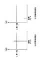
次いで、逆拡散部304では、他局の拡散コードを使用して受信信号が逆拡散される。すなわち、移動局装置A102では受信信号が拡散コードBで逆拡散され、移動局装置B103では受信信号が拡散コードAで逆拡散される。今ここでは、これらの逆拡散結果(すなわち、相関値)がそれぞれ図4に示すようになるものとする。図4は、本発明の実施の形態1に係る移動局装置での逆拡散結果の一例を示す図である。
【0054】
今ここでは、図4(a)に示すように、移動局装置A102では受信信号と拡散コードBとの相関値が所定のしきい値以上となり、図4(b)に示すように、移動局装置B103では受信信号と拡散コードAとの相関値が所定のしきい値よりも小さくなったものとする。これらの相関値は、干渉局検出部308へ出力される。
【0055】
そして、干渉局検出部308では、所定のしきい値と逆拡散部304から出力された相関値の大きさが比較され、相関値が所定のしきい値以上となる拡散コードが割り当てられている移動局装置が自局にとっての干渉局であるとして検出される。
【0056】
つまり、移動局装置A102では、図4(a)に示すように受信信号と拡散コードBとの相関値の大きさが所定のしきい値以上となるので、移動局装置B103が自局にとっての干渉局であると干渉局検出部308によって検出される。そして、移動局装置B103を示す情報が干渉局情報として多重部309へ出力されて、送信データと多重される。
【0057】
また、移動局装置B103では、図4(b)に示すように受信信号と拡散コードAとの相関値の大きさが所定のしきい値より小さくなるので、移動局装置A102が自局にとっての干渉局であるとは検出されない。よって、以下の説明では、移動局装置A102から送信される干渉局情報が多重されたデータに着目して説明する。
【0058】
なお、干渉局検出部308に設定される相関値の大きさのしきい値は、回線品質等に従って適応的に変化させることも可能である。
【0059】
移動局装置A102では、干渉局情報が多重されたデータが、変調部310で所定の変調処理を施され、拡散部311で拡散コードAにより拡散され、送信RF部312で所定の無線処理を施された後、共用器302およびアンテナ301を介して基地局装置101へ送信される。
【0060】
次いで、図2に示す基地局装置101において、アンテナ208および共用器207を介して受信された信号は、受信RF部209で所定の無線処理が施され、逆拡散部210で拡散コードAにより逆拡散され、復調部211で所定の復調処理を施される。復調された信号は、分離部212へ出力される。
【0061】
分離部212では、復調された信号が、受信データと干渉局情報、すなわち移動局装置B103を示す情報とに分離される。そして、移動局装置B103を示す情報が制御部213へ出力される。
【0062】
制御部213では、干渉局情報に従って送信データの送信電力と伝送レートが制御される。すなわち、干渉局情報より干渉局が移動局装置B103であると判断できるため、制御部213が、拡散部204と送信電力調節部205を制御することにより、移動局装置B103宛ての送信データの送信電力を減少させるとともに伝送レートを低下させる。つまり、本実施の形態に係る基地局装置では、干渉局情報で示される干渉局がそのまま、送信電力を減少させる対象の移動局装置となる。
【0063】
送信電力を減少させるとともに伝送レートを低下させるには、具体的には例えば以下のようにする。すなわち、制御部213は、拡散部204へ移動局装置B103宛ての送信データに対する拡散率を前回送信時の2倍にする指示をして、伝送レートを前回送信時の2分の1にする。また、これと同時に、制御部213は、送信電力調節部205へ移動局装置B103宛ての送信データに対する増幅率を前回送信時の2分の1にする指示をして、送信電力を前回送信時の2分の1にする。この指示に従って、拡散部204が拡散コードBの拡散率を前回送信時の2倍にして送信データを拡散するとともに、送信電力調節部205が拡散コードBで拡散された送信データの送信電力を前回送信時の2分の1にする。
【0064】
これにより、移動局装置A102にとっての干渉局である移動局装置B103宛ての送信データの送信電力が減少するため、移動局装置A102に対する干渉量が直接的に減少する。
【0065】
なお、伝送レートを低下させることなく送信電力のみを減少させる方法も考えられるが、本実施の形態に係る基地局装置では、通信品質を維持するために送信電力の減少分に相当する分だけ伝送レートを低下させる構成とした。
【0066】
また、本実施の形態に係る基地局装置では、送信電力を減少させる別の方法として、変調多値数を減少させることにより伝送レートを低下させ、伝送レート低下分に相当する分だけ送信電力を減少させる方法を採ることもできる。この場合、基地局装置の構成は図5に示すようになる。図5は、本発明の実施の形態1に係る基地局装置の別の概略構成を示す要部ブロック図である。
【0067】
図5において、制御部214は、干渉局情報に従って送信データの変調多値数と送信電力を制御する。すなわち、干渉局情報によって判断される干渉局に対応させて、制御部214が、変調部203と送信電力調節部205とを制御することにより、干渉局宛ての送信データの変調多値数を減少させるとともに送信電力を減少させる。
【0068】
具体的には、例えば、制御部214は、変調部203へ干渉局宛ての送信データに対しては変調多値数を前回送信時の2分の1にする指示をして、伝送レートを前回送信時の2分の1にする。また、これと同時に、制御部214は、送信電力調節部205へ干渉局宛ての送信データに対しては、伝送レートの低下量に応じて増幅率を前回送信時より所定量だけ下げる指示をして、送信電力を前回送信時より所定量だけ減少させる。この指示に従って、変調部203が、例えば、前回送信時にQPSKで変調していたものを今回送信時にはBPSKで変調するというように、変調多値数を2分の1にして干渉局宛ての送信データを変調するとともに、送信電力調節部205が干渉局宛ての送信データの送信電力を前回送信時より所定量だけ減少させる。
【0069】
また、本実施の形態に係る基地局装置では、送信電力を減少させる別の方法として、送信電力自体を変更せずに、送信データを間欠的に送信することにより伝送レートを低下させて平均的な送信電力を減少させる方法を採ることもできる。この場合、基地局装置の構成は図6に示すようになる。図6は、本発明の実施の形態1に係る別の基地局装置の概略構成を示す要部ブロック図である。
【0070】
図6において、制御部215は、干渉局情報に従って送信データの送信間隔をを制御する。すなわち、干渉局情報によって判断される干渉局に対応させて、制御部215が、多重部202で行われるフレーム作成処理を制御することにより、干渉局宛ての送信データの送信間隔を制御する。具体的には、制御部215からの制御に従って多重部202が、干渉局宛ての送信データを、例えばフレームの前半だけに格納して出力したり、フレーム内の所定のスロットのみに格納して出力したりする。
【0071】
このように干渉局宛ての送信データを間欠的に送信することにより、瞬時的な送信電力は減少しないが、間欠部分が生じることにより平均的な送信電力は減少する。また、間欠部分では干渉となる信号が送信されないので、間欠部分での干渉は無くなる。よって、平均的に見て干渉量が減少する。
【0072】
なお、干渉キャンセラを移動局装置に搭載して干渉信号を除去する様々な方法が従来開示されている。ところが、干渉キャンセラの装置規模は比較的大きくなるため、干渉キャンセラを移動局装置に搭載するのは現実的には困難である。しかし、本実施の形態によれば、移動局装置の構成は図3に示すように簡易であるので、本実施の形態に係る移動局装置を実現することは現実的に十分可能である。よって、干渉信号を除去するための構成としては、本実施の形態に係る移動局装置の方が、干渉キャンセラを備えた移動局装置よりも適しているといえる。
【0073】
また、本実施の形態では、干渉局に対する送信データの送信電力を減少させるのではなく、干渉局に対するデータの送信自体を打ち切る構成としてもよい。
【0074】
また、本実施の形態では、以下に示すような方法を採ることによっても、干渉を除去することができる。すなわち、基地局装置の上位にある制御局装置が、干渉局を、干渉局が現在位置するセルまたはセクタから、隣接するセルまたはセクタにハンドオーバさせる処理を行うことにより、干渉を除去することができる。
【0075】
また、セル間またはセクタ間でハンドオーバ中にある移動局装置が一方のセルまたはセクタにおいて干渉局と検出された場合に、基地局装置の上位にある制御局装置が、その一方のセルまたはセクタにおいて干渉局の回線を切断することにより、その一方のセルまたはセクタにおける干渉を除去することができる。このような処理を行うと、他方のセルまたはセクタにおいては干渉局として検出されない移動局装置の通信回線を、他方のセルまたはセクタにおいて維持することができる。
【0076】
また、基地局装置が、各移動局装置に対して指向性を形成して信号を送信することにより干渉を除去することができる。例えば、基地局装置が、送信アンテナの指向性を変化させ、大きな干渉を受けている移動局装置が位置する方向にヌル点を形成して、その方向に干渉信号を送信しないようにする(ヌルステアリング)。または、基地局装置が、各移動局装置に対して鋭い指向性を形成して信号を送信する(ビームステアリング)。
【0077】
また、本実施の形態では、基地局装置が移動局装置を示す情報を各移動局装置に報知する構成とした。しかし、本実施の形態では、移動局装置を示す情報を報知することなく、各移動局装置が独自に、他局に割り当てられると考え得るすべての拡散コードについて相関値を求める構成としてもよい。但し、この構成を採ると干渉局の検出に要する時間は、移動局装置を示す情報を報知する構成に比べ長くなる。
【0078】
このように本実施の形態に係る基地局装置、移動局装置および送信電力制御方法によれば、干渉を受けている移動局装置に対する送信信号の送信電力を増加させて干渉量を相対的に小さくするのではなく、干渉の原因となっている移動局装置に対する送信信号の送信電力を減少させることにより干渉量を直接的に減少させるため、移動局装置相互に与える干渉量が増加することを防止することができる。
【0079】
よって、本実施の形態に係る基地局装置、移動局装置および送信電力制御方法によれば、基地局装置が自セル内に収容できる移動局装置数が減少していくことを防止することができ、システム容量が減少してしまうことを防止することができる。
【0080】
(実施の形態2)
本発明の実施の形態2に係る基地局装置は、実施の形態1に係る基地局装置とほぼ同一の構成を有し、複数の干渉局情報を比較することにより、複数の移動局装置に干渉を与えている干渉局をシステム容量の減少に大きな影響を与えている移動局装置として特定し、その特定した移動局装置に対する送信電力を減少させる点において異なる。
【0081】
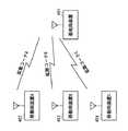
図7は、本発明の実施の形態2に係る基地局装置が移動局装置と通信を行う無線通信システムの概念図である。図7において、基地局装置401は、移動局装置A402、移動局装置B403および移動局装置C404と通信中である。
【0082】
また、移動局装置A402には拡散コードAが割り当てられ、移動局装置B403には拡散コードBが割り当てられ、移動局装置C404には拡散コードCが割り当てられている。すなわち、基地局装置401と移動局装置A402との間で送受信されるデータは拡散コードAで拡散されており、基地局装置401と移動局装置B403との間で送受信されるデータは拡散コードBで拡散されており、基地局装置401と移動局装置C404との間で送受信されるデータは拡散コードCで拡散されている。
【0083】
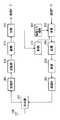
次いで、基地局装置401について説明する。図8は、本発明の実施の形態2に係る基地局装置の構成を示す要部ブロック図である。なお、実施の形態1と同一の構成には同一の符号を付し、詳しい説明は省略する。また、移動局装置A402、移動局装置B403および移動局装置C404の構成については、実施の形態1の図3に示す構成と同一になるため、説明を省略する。
【0084】
図8において、特定部501は、複数の干渉局情報を比較することにより、システム容量の減少に大きな影響を与えている移動局装置を特定する。
【0085】
ここで、各移動局装置での他局の拡散コードよる逆拡散結果が図9に示すようになるものとする。図9は、本発明の実施の形態2に係る移動局装置での逆拡散結果の一例を示す図である。
【0086】
今ここでは、図9(a)に示すように、移動局装置A402では、受信信号と拡散コードBとの相関値が所定のしきい値以上となり、受信信号と拡散コードCとの相関値が所定のしきい値よりも小さくなるものとする。また、図9(b)に示すように、移動局装置B403では、受信信号と拡散コードAとの相関値が所定のしきい値以上となり、受信信号と拡散コードCとの相関値が所定のしきい値よりも小さくなるものとする。また、図9(c)に示すように、移動局装置C404では、受信信号と拡散コードAとの相関値が所定のしきい値よりも小さくなり、受信信号と拡散コードBとの相関値が所定のしきい値以上となるものとする。
【0087】
よって、移動局装置A402からは移動局装置B403を示す情報が、移動局装置B403からは移動局装置A402を示す情報が、移動局装置C404からは移動局装置B403を示す情報が、それぞれ干渉局情報として基地局装置401へ送信される。
【0088】
図8に示す基地局装置401においては、分離部212で分離された干渉局情報が特定部501へ出力される。特定部501では、各移動局装置から送信された干渉局情報が比較されることにより、システム容量の減少に大きな影響を与えている移動局が特定される。すなわち、本実施の形態に係る基地局装置では、干渉局情報で示される干渉局がそのまま、送信電力を減少させる対象の移動局装置にはならない。
【0089】
具体的には、特定部501は、移動局装置A402からは移動局装置B403を示す情報が、移動局装置B403からは移動局装置A402を示す情報が、移動局装置C404からは移動局装置B403を示す情報が送信されたので、最も多くの数の移動局装置に干渉を与えている移動局装置B403を、システム容量の減少に最も大きな影響を与えている移動局装置として特定する。
【0090】
そして、特定部501が、移動局装置B103を示す情報を制御部213へ出力し、制御部213が、その情報に従って移動局装置B103宛ての送信データの送信電力を減少させ、伝送レートを低下させる。
【0091】
このように本実施の形態に係る基地局装置および送信電力制御方法によれば、複数の干渉局情報を比較することにより、複数の移動局装置に干渉を与えている干渉局をシステム容量の減少に大きな影響を与えている移動局装置として特定し、その特定した移動局装置に対する送信電力を減少させるため、システム容量の減少に大きな影響を与えている干渉ほど優先的に除去することができるので、干渉量の減少の効率を上げることができる。
【0092】
また、実施の形態に係る基地局装置および送信電力制御方法によれば、複数の干渉局情報に基づいて送信電力を減少させるべき移動局装置を特定するため、送信電力を減少させるべき移動局装置をより確実に特定することができるので、干渉量をより確実に減少させることができる。
【0093】
(実施の形態3)
本発明の実施の形態3に係る基地局装置は、実施の形態1および実施の形態2に係る基地局装置とほぼ同一の構成を有し、ある移動局装置から報告された干渉局情報に従って送信電力を減少させるべき移動局装置を決定してよいか否か各移動局装置に再度確認してから、送信電力を減少させるべき移動局装置を特定する点において異なる。
【0094】
図10は、本発明の実施の形態3に係る基地局装置の構成を示す要部ブロック図である。なお、実施の形態2と同一の構成には同一の符号を付し、詳しい説明は省略する。
【0095】
図10において、拡散コード報知部601は、実施の形態1および実施の形態2で説明した動作に加えて、分離部212から出力された干渉局情報で示される移動局装置に割り当てられている拡散コードを各移動局装置へ報知する。特定部602は、複数回干渉局として報告された移動局装置を送信電力を減少させるべき移動局装置として特定する。
【0096】
つまり、本実施の形態に係る基地局装置では、ある移動局装置から報告された干渉局情報に従って送信電力を減少させるべき移動局装置を特定してよいか否か、拡散コード報知部601によって各移動局装置に再度確認される。
【0097】
各移動局装置では、自局にとっての干渉局の検出が再び行われ、干渉局情報が改めて生成されて基地局装置へ送信される。
【0098】
基地局装置では、特定部602によって、再度報告された干渉局情報が参照されて、各移動局装置から複数回干渉局として報告された移動局装置が、送信電力を減少させるべき移動局装置として特定される。
【0099】
このように本実施の形態に係る基地局装置および送信電力制御方法によれば、ある移動局装置から報告された干渉局情報に従って送信電力を減少させるべき移動局装置を決定してよいか否か各移動局装置に再度確認してから、送信電力を減少させるべき移動局装置を特定するため、誤った干渉局情報に基づいて送信電力を減少させるべき移動局装置が特定されてしまう可能性を低くすることができる。つまり、本実施の形態に係る基地局装置および送信電力制御方法によれば、各移動局装置において複数回検出された干渉局を送信電力を減少させるべき移動局装置として特定するため、より確実な情報に基づいて送信電力を減少させるべき移動局装置を特定することができる。
【0100】
また、本実施の形態に係る基地局装置および送信電力制御方法によれば、他局の拡散コードでの拡散結果がしきい値近辺で上下する状況に移動局装置がある場合等にも、再度確認してから送信電力を減少させるべき移動局装置が最終的に特定されるため、より確実な情報に基づいて送信電力を減少させるべき移動局装置を特定することができる。
【0101】
なお、本願発明を、本発明者が先にした伝送レート制御方法に関する発明に適用することも可能である。この伝送レート制御方法に関する発明は、無線リソース層で設定された許容送信電力と、無線リソース層よりも下位の物理層で求められた平均送信電力とを比較して、平均送信電力が許容送信電力よりも大きいときに物理層より上位であり無線リソース層よりも下位である媒体アクセス層において伝送レートを下げるものである。この発明は、特願平11−111301号に記載されている。この内容は、すべてここに含めておく。この発明に本願発明を適用する際には、干渉局に対する許容送信電力の値を小さくするように制御する。よって、選択可能な伝送レートが必然的に低下するため、干渉局に対する送信電力を減少させることができる。
【発明の効果】
以上説明したように、本発明によれば、システム容量を減少させないように適切な送信電力制御を行うことができる。
【図面の簡単な説明】
【図1】本発明の実施の形態1に係る基地局装置と本発明の実施の形態1に係る移動局装置とが通信を行う無線通信システムの概念図
【図2】本発明の実施の形態1に係る基地局装置の構成を示す要部ブロック図
【図3】本発明の実施の形態1に係る移動局装置の構成を示す要部ブロック図
【図4】本発明の実施の形態1に係る移動局装置での逆拡散結果の一例を示す図
【図5】本発明の実施の形態1に係る基地局装置の別の概略構成を示す要部ブロック図
【図6】本発明の実施の形態1に係る別の基地局装置の概略構成を示す要部ブロック図
【図7】本発明の実施の形態2に係る基地局装置が移動局装置と通信を行う無線通信システムの概念図
【図8】本発明の実施の形態2に係る基地局装置の構成を示す要部ブロック図
【図9】本発明の実施の形態2に係る移動局装置での逆拡散結果の一例を示す図
【図10】本発明の実施の形態3に係る基地局装置の構成を示す要部ブロック図
【符号の説明】
201 拡散コード報知部
202 多重部
203 変調部
204 拡散部
205 送信電力調節部
212 分離部
213 制御部
304 逆拡散部
306 分離部
307 拡散コード指定部
308 干渉局検出部
309 多重部
214 制御部
215 制御部
501 特定部
601 拡散コード報知部
602 特定部[0001]
BACKGROUND OF THE INVENTION
The present invention relates to a base station apparatus, a mobile station apparatus, and a transmission power control method.
[0002]
[Prior art]
In a mobile communication system using the CDMA system, transmission power control is performed in order to solve a so-called perspective problem. The transmission power control is roughly classified into an open loop type transmission power control and a closed loop type transmission power control.
[0003]
Among these, when closed-loop transmission power control is applied to a downlink (a line from the base station to the mobile station), the mobile station and the base station operate as follows.
[0004]
That is, the mobile station measures SIR (Signal to Interference Ratio) indicating the quality of the received signal, and compares the measured SIR with the target SIR. When the measured SIR is larger than the target SIR, the mobile station sends an instruction to lower the transmission power to the base station, and when the measured SIR is less than the target SIR, the mobile station gives an instruction to increase the transmission power. Send to base station. The base station increases or decreases the transmission power according to this command.
[0005]
Thus, in closed-loop transmission power control performed on the downlink, the mobile station instructs the base station to increase or decrease the transmission power based on the amount of interference received by the mobile station.
[0006]
[Problems to be solved by the invention]
Here, in the CDMA system, since the base station communicates with a plurality of mobile stations at the same time in the same frequency band, an increase in transmission power for a certain mobile station increases the amount of interference with other mobile stations other than that mobile station. Cause it. In addition, the mobile station whose interference amount has increased sends a command to increase the transmission power to the base station in order to maintain the reception quality. When the base station increases the transmission power for the mobile station that transmitted the command, the amount of interference with other mobile stations other than the mobile station increases.
[0007]
When such a series of operations is repeated, the transmission power for all mobile stations gradually increases, and the amount of interference with other mobile stations also increases accordingly. If the amount of interference given to mobile stations gradually increases in this way, the amount of interference given to each other may increase unacceptably. As a result, the number of mobile stations that the base station can accommodate in its own cell is significantly reduced. That is, the system capacity is significantly reduced.
[0008]
The present invention has been made in view of such a point, and an object thereof is to provide a base station apparatus, a mobile station apparatus, and a transmission power control method capable of performing appropriate transmission power control so as not to reduce the system capacity. To do.
[0009]
[Means for Solving the Problems]
The base station apparatus of the present inventionInterference station information indicating an interfering station that is a mobile station that interferes with other mobile stations among a plurality of mobile stations in communicationReceiving means for receivingA transmission means for transmitting a signal to each of the plurality of mobile stations, and a signal transmitted to the interference station among signals transmitted from the transmission means in accordance with the interference station informationAnd a control means for reducing the transmission power of the transmission.
[0010]
According to this configuration, the transmission power of the transmission signal to the mobile station apparatus receiving the interference is not increased to relatively reduce the amount of interference, but the transmission signal of the transmission signal to the mobile station apparatus causing the interference is reduced. Since the amount of interference is directly reduced by reducing the transmission power, it is possible to prevent the amount of interference given to the mobile station apparatuses from increasing.
[0012]
The base station apparatus of the present inventionAssigned to each of the plurality of mobile stationsInformation indicating the spreading codeIn addition, it further comprises notification means for reporting to the plurality of mobile stations.Take the configuration.
[0013]
thisAccording to the configuration, since the base station device notifies each mobile station device of information (for example, a spreading code) indicating the mobile station device, each mobile station device can narrow down other stations to be investigated, so that interference occurs. The time required for station detection can be shortened.
[0015]
The base station apparatus of the present inventionThe control means reduces transmission power of a signal transmitted to the interference station that interferes with a plurality of mobile stations.Take the configuration.
[0016]
thisAccording to the configuration, in order to reduce the transmission power for the specified mobile station device by identifying an interference station that has interfered with a plurality of mobile station devices as a mobile station device that has a large influence on the reduction in system capacity Therefore, the interference that has a great influence on the reduction of the system capacity can be preferentially removed.
[0017]
The base station apparatus of the present inventionThe control means reduces transmission power of a signal transmitted to the interference station indicated multiple times by the interference station information received from the same mobile station.Take the configuration.
[0018]
According to this configuration, in order to identify an interference station detected multiple times in each mobile station device as a mobile station device whose transmission power should be reduced, the mobile station device whose transmission power should be reduced based on more reliable information. Can be identified.
[0019]
The base station apparatus of the present inventionSaidThe control meansWhile reducing the transmission power of the signal transmitted to the interfering station, the signal transmitted to the interfering stationA configuration for reducing the transmission rate is adopted.
[0020]
The base station apparatus of the present inventionSaidThe control meansOf signals transmitted to the interfering stationBy increasing the diffusion rateSaidA configuration for reducing the transmission rate is adopted.
[0021]
The base station apparatus of the present inventionSaidThe control meansReduce the modulation level of signals transmitted to the interfering stationBySaidA configuration for reducing the transmission rate is adopted.
[0022]
According to these configurations, since the transmission rate is reduced according to the decrease in transmission power, the communication quality can be maintained.
[0023]
The base station apparatus of the present inventionSaidThe control meansThe signal transmitted to the interference stationIntermittentlySendBySaidA configuration for reducing the transmission rate is adopted.
[0024]
According to this configuration, since an intermittent portion is generated in the transmission signal, the amount of interference can be reduced on average.
[0025]
The mobile station apparatus of the present inventionOther mobile stations that interfere withDetection means for detecting the interfering station and the detected interfering stationInterfering station information to base stationAnd a transmission means for transmitting.
[0026]
According to this configuration, the transmission power of the transmission signal to the mobile station apparatus receiving the interference is not increased to relatively reduce the amount of interference, but the transmission signal of the transmission signal to the mobile station apparatus causing the interference is reduced. Since the amount of interference is directly reduced by reducing the transmission power, it is possible to prevent the amount of interference given to the mobile station apparatuses from increasing.
[0029]
The mobile station apparatus of the present invention isDespreading means for despreading the received signal with a spreading code assigned to another mobile station in communication with the base station to obtain a correlation value between the spreading code and the received signal;The detection means isThe correlation value is greater than or equal to a threshold valueSpreading codeOther mobile stations that are assignedTheSaidA configuration for detecting as an interference station is adopted.
[0030]
According to this configuration, the transmission power of the transmission signal to the mobile station apparatus receiving the interference is not increased to relatively reduce the amount of interference, but the transmission signal of the transmission signal to the mobile station apparatus causing the interference is reduced. Since the amount of interference is directly reduced by reducing the transmission power, it is possible to prevent the amount of interference given to the mobile station apparatuses from increasing.
[0031]
The transmission power control method of the present invention includes:A transmission power control method used in a mobile communication system having a plurality of mobile stations and a base station communicating simultaneously with the plurality of mobile stations, wherein each of the plurality of mobile stations Detecting an interference station that is another mobile station that causes interference, and transmitting interference station information indicating the detected interference station to the base station,
Of the signals that the base station receives the interference station information and transmits from the base station to each of the plurality of mobile stations according to the interference station informationInterfering stationSignal to send toThe transmission power of was reduced.
[0032]
According to this method, the transmission power of the transmission signal to the mobile station apparatus receiving the interference is not increased to reduce the amount of interference relatively, but the transmission signal of the transmission signal to the mobile station apparatus causing the interference is reduced. Since the amount of interference is directly reduced by reducing the transmission power, it is possible to prevent the amount of interference given to the mobile station apparatuses from increasing.
[0035]
DETAILED DESCRIPTION OF THE INVENTION
In order to obtain the desired reception quality, the present inventor has a method of decreasing the transmission power of the interference signal in addition to the method of increasing the transmission power of the desired signal when the mobile station receives interference. Paying attention to this, by reducing the transmission power of the signal to the mobile station causing the interference, it is possible to obtain the desired reception quality at each mobile station and to reduce the amount of interference between the mobile stations. As a result, the present inventors have found that it is possible to prevent the system capacity from being reduced.
[0036]
That is, the gist of the present invention is not to relatively reduce the amount of interference by increasing the transmission power of the signal to the mobile station receiving the interference, but to transmit the signal to the mobile station causing the interference. The amount of interference is directly reduced by reducing the power.
[0037]
Embodiments of the present invention will be described below with reference to the drawings.
(Embodiment 1)
FIG. 1 is a conceptual diagram of a radio communication system in which a base station apparatus according to Embodiment 1 of the present invention and a mobile station apparatus according to Embodiment 1 of the present invention communicate. In FIG. 1, a
[0038]
Also, spreading code A is assigned to mobile station apparatus A102, and spreading code B is assigned to mobile station apparatus B103. That is, data transmitted / received between
[0039]
Next, the configuration of
[0040]
In FIG. 2, a spreading
[0041]
The
[0042]
Next, the configuration of mobile station apparatus A102 and mobile station apparatus B103 will be described. FIG. 3 is a principal block diagram showing the configuration of the mobile station apparatus according to Embodiment 1 of the present invention. Mobile station apparatus A102 and mobile station apparatus B103 have the same configuration.
[0043]
In FIG. 3, a
[0044]
The interference
[0045]
Next, operations of the base station apparatus and mobile station apparatus having the above-described configurations will be described. First, in
[0046]
In
[0047]
Data in which information indicating the spread code A and information indicating the spread code B are multiplexed is subjected to a predetermined modulation process by the
[0048]
The transmission data whose transmission power is adjusted is subjected to predetermined radio processing by the
[0049]
Next, in mobile
[0050]
In the
[0051]
The despread signal is subjected to predetermined demodulation processing by the
[0052]
In the spreading
[0053]
Next, the
[0054]
Now, as shown in FIG. 4 (a), in mobile station apparatus A102, the correlation value between the received signal and spreading code B is equal to or greater than a predetermined threshold value, and as shown in FIG. In apparatus B103, it is assumed that the correlation value between the received signal and spreading code A is smaller than a predetermined threshold value. These correlation values are output to the interference
[0055]
Interference
[0056]
That is, in the mobile station apparatus A102, the magnitude of the correlation value between the received signal and the spread code B is equal to or greater than a predetermined threshold as shown in FIG. The interference
[0057]
Further, in mobile station apparatus B103, as shown in FIG. 4 (b), the correlation value between the received signal and spreading code A is smaller than a predetermined threshold value. It is not detected to be an interfering station. Therefore, in the following description, description will be given focusing on data in which interference station information transmitted from mobile station apparatus A102 is multiplexed.
[0058]
Note that the threshold value of the correlation value set in the interference
[0059]
In the mobile station apparatus A102, the data on which the interference station information is multiplexed is subjected to predetermined modulation processing by the
[0060]
Next, in the
[0061]
In the
[0062]
The
[0063]
Specifically, for example, the following is performed in order to reduce the transmission power and the transmission rate. That is, the
[0064]
As a result, the transmission power of the transmission data addressed to the mobile station apparatus B103, which is an interference station for the mobile station apparatus A102, decreases, and the amount of interference with the mobile station apparatus A102 directly decreases.
[0065]
Although a method of reducing only the transmission power without reducing the transmission rate is also conceivable, the base station apparatus according to the present embodiment transmits only the amount corresponding to the decrease in transmission power in order to maintain communication quality. It was set as the structure which reduces a rate.
[0066]
Further, in the base station apparatus according to the present embodiment, as another method for reducing the transmission power, the transmission rate is reduced by reducing the number of modulation multi-values, and the transmission power is reduced by an amount corresponding to the transmission rate reduction. It is also possible to take a method of decreasing. In this case, the configuration of the base station apparatus is as shown in FIG. FIG. 5 is a principal block diagram showing another schematic configuration of the base station apparatus according to Embodiment 1 of the present invention.
[0067]
In FIG. 5, the
[0068]
Specifically, for example, the
[0069]
Further, in the base station apparatus according to the present embodiment, as another method for reducing the transmission power, the transmission data is intermittently transmitted without changing the transmission power itself, thereby reducing the transmission rate and averaging. It is also possible to reduce the transmission power. In this case, the configuration of the base station apparatus is as shown in FIG. FIG. 6 is a principal block diagram showing a schematic configuration of another base station apparatus according to Embodiment 1 of the present invention.
[0070]
In FIG. 6, the
[0071]
By transmitting transmission data addressed to the interference station intermittently in this way, the instantaneous transmission power is not reduced, but the average transmission power is reduced due to the occurrence of intermittent portions. In addition, since the signal that causes interference is not transmitted in the intermittent portion, interference in the intermittent portion is eliminated. Therefore, the amount of interference decreases on average.
[0072]
Various methods for removing an interference signal by mounting an interference canceller on a mobile station apparatus have been conventionally disclosed. However, since the apparatus scale of the interference canceller becomes relatively large, it is practically difficult to mount the interference canceller on the mobile station apparatus. However, according to the present embodiment, since the configuration of the mobile station apparatus is simple as shown in FIG. 3, it is practically possible to realize the mobile station apparatus according to the present embodiment. Therefore, it can be said that the mobile station apparatus according to the present embodiment is more suitable as a configuration for removing the interference signal than the mobile station apparatus provided with the interference canceller.
[0073]
Further, in the present embodiment, the transmission power of transmission data to the interference station may not be reduced, but the data transmission itself to the interference station may be terminated.
[0074]
In the present embodiment, interference can also be removed by adopting the following method. That is, the control station apparatus located above the base station apparatus can remove the interference by performing a process of handing over the interference station from the cell or sector where the interference station is currently located to the adjacent cell or sector. .
[0075]
In addition, when a mobile station apparatus that is performing handover between cells or sectors is detected as an interference station in one cell or sector, a control station apparatus that is higher than the base station apparatus By disconnecting the line of the interfering station, interference in one cell or sector can be removed. By performing such processing, the communication line of the mobile station apparatus that is not detected as an interference station in the other cell or sector can be maintained in the other cell or sector.
[0076]
In addition, the base station apparatus can remove interference by forming a directivity with respect to each mobile station apparatus and transmitting a signal. For example, the base station apparatus changes the directivity of the transmission antenna, forms a null point in the direction where the mobile station apparatus receiving large interference is located, and prevents the interference signal from being transmitted in that direction (null) Steering). Alternatively, the base station apparatus forms a sharp directivity with respect to each mobile station apparatus and transmits a signal (beam steering).
[0077]
Moreover, in this Embodiment, it was set as the structure which alert | reports the information which shows a base station apparatus to a mobile station apparatus to each mobile station apparatus. However, the present embodiment may be configured such that each mobile station device independently obtains a correlation value for all spreading codes that can be considered to be assigned to other stations without notifying information indicating the mobile station device. However, when this configuration is adopted, the time required to detect the interference station becomes longer than the configuration in which information indicating the mobile station device is broadcast.
[0078]
As described above, according to the base station apparatus, mobile station apparatus, and transmission power control method according to the present embodiment, the transmission power of the transmission signal for the mobile station apparatus receiving interference is increased to relatively reduce the amount of interference. Instead of reducing the amount of interference directly by reducing the transmission power of the transmission signal to the mobile station device causing the interference, it is possible to prevent the amount of interference given to the mobile station devices from increasing. can do.
[0079]
Therefore, according to the base station apparatus, mobile station apparatus and transmission power control method according to the present embodiment, it is possible to prevent the number of mobile station apparatuses that can be accommodated in the own cell from decreasing. Therefore, it is possible to prevent the system capacity from being reduced.
[0080]
(Embodiment 2)
The base station apparatus according to Embodiment 2 of the present invention has substantially the same configuration as the base station apparatus according to Embodiment 1, and interferes with a plurality of mobile station apparatuses by comparing a plurality of interference station information. This is different in that the interfering station that gives the signal is identified as a mobile station apparatus that has a large influence on the reduction in system capacity, and the transmission power for the identified mobile station apparatus is reduced.
[0081]
FIG. 7 is a conceptual diagram of a radio communication system in which a base station apparatus according to Embodiment 2 of the present invention communicates with a mobile station apparatus. In FIG. 7, the
[0082]
Also, spreading code A is assigned to mobile
[0083]
Next, the
[0084]
In FIG. 8, the identifying
[0085]
Here, it is assumed that the result of despreading by the spreading code of the other station in each mobile station apparatus is as shown in FIG. FIG. 9 is a diagram illustrating an example of a despreading result in the mobile station apparatus according to Embodiment 2 of the present invention.
[0086]
Now, as shown in FIG. 9 (a), in mobile station apparatus A402, the correlation value between the received signal and spreading code B is equal to or greater than a predetermined threshold value, and the correlation value between the received signal and spreading code C is It is assumed that it becomes smaller than a predetermined threshold value. Also, as shown in FIG. 9B, in mobile station apparatus B403, the correlation value between the received signal and spreading code A is equal to or greater than a predetermined threshold value, and the correlation value between the received signal and spreading code C is a predetermined value. It is assumed that it becomes smaller than the threshold value. Further, as shown in FIG. 9C, in the mobile station apparatus C404, the correlation value between the received signal and the spreading code A becomes smaller than a predetermined threshold value, and the correlation value between the received signal and the spreading code B becomes smaller. It shall be above a predetermined threshold.
[0087]
Therefore, information indicating the mobile station device B403 from the mobile station device A402, information indicating the mobile station device A402 from the mobile station device B403, and information indicating the mobile station device B403 from the mobile station device C404, respectively. Information is transmitted to the
[0088]
In the
[0089]
Specifically, the identifying
[0090]
Then, the identifying
[0091]
As described above, according to the base station apparatus and the transmission power control method according to the present embodiment, by comparing a plurality of pieces of interference station information, it is possible to reduce the system capacity of the interference stations that cause interference to the plurality of mobile station apparatuses. Therefore, it is possible to preferentially remove the interference that has a large influence on the reduction of the system capacity because the transmission power for the specified mobile station apparatus is reduced. , The efficiency of reducing the amount of interference can be increased.
[0092]
Further, according to the base station apparatus and the transmission power control method according to the embodiment, the mobile station apparatus whose transmission power is to be reduced is specified in order to identify the mobile station apparatus whose transmission power is to be reduced based on a plurality of pieces of interference station information. Can be identified more reliably, and the amount of interference can be reduced more reliably.
[0093]
(Embodiment 3)
The base station apparatus according to Embodiment 3 of the present invention has substantially the same configuration as the base station apparatus according to Embodiment 1 and Embodiment 2, and transmits according to the interference station information reported from a certain mobile station apparatus. It is different in that the mobile station apparatus whose power should be reduced is identified after confirming again with each mobile station apparatus whether or not the mobile station apparatus whose power should be reduced can be determined.
[0094]
FIG.10 is a principal block diagram showing the configuration of the base station apparatus according to Embodiment 3 of the present invention. In addition, the same code | symbol is attached | subjected to the structure same as Embodiment 2, and detailed description is abbreviate | omitted.
[0095]
10, in addition to the operations described in the first and second embodiments, the spreading
[0096]
That is, in the base station apparatus according to the present embodiment, whether or not the mobile station apparatus whose transmission power should be reduced according to the interference station information reported from a certain mobile station apparatus may be specified by spreading
[0097]
In each mobile station apparatus, the detection of the interference station for the own station is performed again, and the interference station information is newly generated and transmitted to the base station apparatus.
[0098]
In the base station apparatus, the mobile station apparatus reported as an interference station multiple times from each mobile station apparatus with reference to the interference station information reported again by the identifying
[0099]
Thus, according to the base station apparatus and transmission power control method according to the present embodiment, whether or not to determine a mobile station apparatus whose transmission power should be reduced according to interference station information reported from a certain mobile station apparatus is determined. After confirming again with each mobile station apparatus, the mobile station apparatus whose transmission power should be reduced is specified, and therefore, there is a possibility that the mobile station apparatus whose transmission power should be reduced is specified based on erroneous interference station information. Can be lowered. That is, according to the base station apparatus and the transmission power control method according to the present embodiment, the interference station detected multiple times in each mobile station apparatus is identified as the mobile station apparatus whose transmission power should be reduced, and therefore more reliable. Based on the information, it is possible to identify the mobile station apparatus whose transmission power should be reduced.
[0100]
In addition, according to the base station apparatus and the transmission power control method according to the present embodiment, even when the mobile station apparatus is in a situation where the spreading result of the spreading code of the other station goes up and down near the threshold, etc. Since the mobile station apparatus whose transmission power should be reduced after the confirmation is finally identified, the mobile station apparatus whose transmission power should be reduced can be identified based on more reliable information.
[0101]
The present invention can also be applied to an invention relating to a transmission rate control method previously performed by the present inventors. The invention relating to this transmission rate control method compares the allowable transmission power set in the radio resource layer with the average transmission power obtained in the physical layer lower than the radio resource layer, and the average transmission power is equal to the allowable transmission power. The transmission rate is lowered in the medium access layer, which is higher than the physical layer and lower than the radio resource layer when it is larger than the physical layer. This invention is described in Japanese Patent Application No. 11-111301. All this content is included here. When the present invention is applied to this invention, control is performed so as to reduce the value of the allowable transmission power for the interference station. Therefore, since the selectable transmission rate is inevitably reduced, the transmission power for the interference station can be reduced.
【The invention's effect】
As described above, according to the present invention, appropriate transmission power control can be performed without reducing the system capacity.
[Brief description of the drawings]
FIG. 1 is a conceptual diagram of a radio communication system in which a base station apparatus according to Embodiment 1 of the present invention and a mobile station apparatus according to Embodiment 1 of the present invention communicate with each other.
FIG. 2 is a principal block diagram showing a configuration of a base station apparatus according to Embodiment 1 of the present invention.
FIG. 3 is a principal block diagram showing a configuration of a mobile station apparatus according to Embodiment 1 of the present invention.
FIG. 4 is a diagram showing an example of a despreading result in the mobile station apparatus according to Embodiment 1 of the present invention.
FIG. 5 is a principal block diagram showing another schematic configuration of the base station apparatus according to Embodiment 1 of the present invention;
FIG. 6 is a principal block diagram showing a schematic configuration of another base station apparatus according to Embodiment 1 of the present invention;
FIG. 7 is a conceptual diagram of a radio communication system in which a base station apparatus according to Embodiment 2 of the present invention communicates with a mobile station apparatus.
FIG. 8 is a principal block diagram showing the configuration of a base station apparatus according to Embodiment 2 of the present invention.
FIG. 9 is a diagram showing an example of a despreading result in a mobile station apparatus according to Embodiment 2 of the present invention.
FIG. 10 is a principal block diagram showing the configuration of a base station apparatus according to Embodiment 3 of the present invention.
[Explanation of symbols]
201 Spreading code notification unit
202 Multiplexer
203 Modulator
204 Diffusion unit
205 Transmission power adjustment unit
212 Separation unit
213 Control unit
304 Despreading part
306 Separator
307 Spreading code designation part
308 Interference station detector
309 Multiplexer
214 Control unit
215 control unit
501 Specific part
601 Spreading code notification unit
602 Specific part
Claims (11)
Translated fromJapanese前記複数の移動局の各々へ信号を送信する送信手段と、
前記干渉局情報に従って、前記送信手段から送信される信号のうち前記干渉局へ送信される信号の送信電力を減少させる制御手段と、
を具備することを特徴とする基地局装置。Receiving means for receivinginterference station information indicating an interference station that is a mobile station that interferes with other mobile stations among a plurality of mobile stations in communication ; and
Transmitting means for transmitting a signal to each of the plurality of mobile stations;
Control means for reducing transmission power ofa signal transmitted to the interference station among signals transmitted from the transmission means in accordance with the interference station information ;
A base station apparatus comprising:
をさらに具備することを特徴とする請求項1記載の基地局装置。Informing means for informing the plurality of mobile stations of information indicatinga spreading codeassigned to each of theplurality of mobile stations,
The base station apparatus according toclaim 1, further comprising:
ことを特徴とする請求項1記載の基地局装置。The control means reduces transmission power of a signal transmitted to the interference station that causes interference to a plurality of mobile stations;
The base station apparatus according toclaim 1 .
ことを特徴とする請求項1記載の基地局装置。The control means reduces transmission power of a signal transmitted to the interference station indicated multiple times by the interference station information received from the same mobile station.
The base station apparatus according toclaim 1 .
ことを特徴とする請求項1記載の基地局装置。The control meansreduces the transmission power of the signal transmitted to the interference station and decreases the transmission rate of thesignal transmitted to the interference station.
The base station apparatus according toclaim 1 .
ことを特徴とする請求項5記載の基地局装置。The control means reducesthe transmission rate by increasing the spreading factorof the signal to be transmitted to the interferingstation,
The base station apparatus according toclaim 5 .
ことを特徴とする請求項5記載の基地局装置。The control means reducesthe transmission rateby reducing the modulation level of the signal to be transmitted to the interferingstation,
The base station apparatus according toclaim 5 .
ことを特徴とする請求項5記載の基地局装置。The control means reducesthe transmission rateby transmittinga signal to be transmitted to the interfering stationintermittently,
The base station apparatus according toclaim 5 .
検出された干渉局を示す干渉局情報を基地局へ送信する送信手段と、
を具備することを特徴とする移動局装置。Detecting means for detecting an interfering station thatis another mobile stationthat interferes with the own station;
Transmitting meansfor transmittingto the base station interference station information indicating the detected interference station;
A mobile station apparatus comprising:
前記検出手段は、前記相関値がしきい値以上となる拡散コードが割り当てられている他の移動局を前記干渉局として検出する、
ことを特徴とする請求項9記載の移動局装置。Despreading means for despreading a received signal with a spreading code assigned to another mobile station in communication with the base station to obtain a correlation value between the spreading code and the received signal;
It said detection means detects theother mobile stations spread codeswhich the correlation value is equal to or greater than a threshold valueis assigned asthe interferingstation,
The mobile station apparatus according toclaim 9 .
前記複数の移動局の各々が、自局に対して干渉を与える他の移動局である干渉局を検出し、検出した干渉局を示す干渉局情報を前記基地局へ送信し、
前記基地局が、前記干渉局情報を受信し、前記干渉局情報に従って、前記基地局から前記複数の移動局の各々へ送信する信号のうち前記干渉局へ送信する信号の送信電力を減少させる、
ことを特徴とする送信電力制御方法。A transmission power control method used in a mobile communication system having a plurality of mobile stations and a base station communicating simultaneously with the plurality of mobile stations,
Each of the plurality of mobile stations detectsan interference station thatis another mobile station that interferes with the mobile station, and transmitsinterference station information indicating the detected interference station to thebase station ,
The base station receives the interference station information, and reduces transmission power ofa signal transmitted to the interference stationamong signals transmitted from the base station to each of the plurality of mobile stations according to the interference station information.
A transmission power control method characterized by the above.
Applications Claiming Priority (1)
| Application Number | Priority Date | Filing Date | Title |
|---|---|---|---|
| PCT/JP2001/010208WO2003044988A1 (en) | 2001-11-22 | 2001-11-22 | Base station device, mobile station device and transmission power controlling method |
Publications (2)
| Publication Number | Publication Date |
|---|---|
| JP2001339342A JP2001339342A (en) | 2001-12-07 |
| JP3607854B2true JP3607854B2 (en) | 2005-01-05 |
Family
ID=28080680
Family Applications (1)
| Application Number | Title | Priority Date | Filing Date |
|---|---|---|---|
| JP2000157166AExpired - Fee RelatedJP3607854B2 (en) | 2001-11-22 | 2000-05-26 | Base station apparatus, mobile station apparatus, and transmission power control method |
Country Status (6)
| Country | Link |
|---|---|
| US (1) | US7167676B2 (en) |
| EP (1) | EP1353455A4 (en) |
| JP (1) | JP3607854B2 (en) |
| CN (1) | CN1258268C (en) |
| AU (1) | AU2002224073A1 (en) |
| WO (1) | WO2003044988A1 (en) |
Families Citing this family (29)
| Publication number | Priority date | Publication date | Assignee | Title |
|---|---|---|---|---|
| EP2426826A1 (en)* | 2002-03-25 | 2012-03-07 | InterDigital Technology Corporation | Method and apparatus for blind code detection |
| US8213553B2 (en) | 2004-04-12 | 2012-07-03 | The Directv Group, Inc. | Method and apparatus for identifying co-channel interference |
| US7672285B2 (en) | 2004-06-28 | 2010-03-02 | Dtvg Licensing, Inc. | Method and apparatus for minimizing co-channel interference by scrambling |
| JP2008500747A (en)* | 2004-04-12 | 2008-01-10 | ザ・ディレクティービー・グループ・インコーポレイテッド | Method and apparatus for minimizing co-channel interference |
| US7161988B2 (en) | 2004-04-12 | 2007-01-09 | The Directv Group, Inc. | Method and apparatus for minimizing co-channel interference |
| US8355748B2 (en) | 2004-05-28 | 2013-01-15 | Panasonic Corporation | Multi-mode control station, radio communication system, radio station, and radio communication control method |
| AU2005253330A1 (en)* | 2004-06-07 | 2005-12-22 | Nec Corporation | Method and system for determining residence within service area in mobile communication network |
| CN101835283B (en)* | 2004-06-29 | 2012-07-11 | 夏普株式会社 | terminal device |
| WO2006005223A1 (en)* | 2004-07-12 | 2006-01-19 | Zte Corporation | The method of dynamic adjusting for the spreading factor in the wcdma system |
| US8396153B1 (en) | 2004-12-07 | 2013-03-12 | Adaptix, Inc. | Cooperative MIMO in multicell wireless networks |
| CN101116365A (en) | 2005-02-18 | 2008-01-30 | 富士通株式会社 | Base station and method for reducing interference in the base station |
| JP4738904B2 (en)* | 2005-06-08 | 2011-08-03 | 京セラ株式会社 | Base station apparatus, parameter changeable mobile station apparatus selection method, and program |
| DE602005015721D1 (en)* | 2005-06-15 | 2009-09-10 | Alcatel Lucent | Uplink interference coordination method in monofrequency networks, base station and mobile network therefor |
| US7257376B2 (en) | 2005-06-30 | 2007-08-14 | Adaptix, Inc. | Systems and methods for making channel assignments to reduce interference and increase capacity of wireless networks |
| US8700082B2 (en)* | 2006-01-05 | 2014-04-15 | Qualcomm Incorporated | Power control utilizing multiple rate interference indications |
| US8958752B2 (en)* | 2006-05-10 | 2015-02-17 | Alcatel Lucent | Method of managing interference in a wireless communication system |
| US7949315B2 (en)* | 2007-09-25 | 2011-05-24 | Broadcom Corporation | Power consumption management and data rate control based on transmit power and method for use therewith |
| US8228809B1 (en) | 2007-12-21 | 2012-07-24 | Adaptix, Inc. | Intelligent mode switching in communication networks |
| US8258942B1 (en) | 2008-01-24 | 2012-09-04 | Cellular Tracking Technologies, LLC | Lightweight portable tracking device |
| US8504091B2 (en)* | 2008-02-01 | 2013-08-06 | Qualcomm Incorporated | Interference mitigation for control channels in a wireless communication network |
| US8599705B2 (en) | 2008-02-01 | 2013-12-03 | Qualcomm Incorporated | Interference management based on enhanced pilot measurement reports |
| ES2353445T3 (en) | 2008-02-15 | 2011-03-02 | Telefonaktiebolaget Lm Ericsson (Publ) | METHODS, DEVICES AND SYSTEMS FOR PROCESSING A SIGNAL IN THE PRESENCE OF NARROW BAND INTERFERENCES. |
| US8170488B2 (en)* | 2008-03-11 | 2012-05-01 | Intel Corporation | Mitigation of internetwork interference |
| JP5199005B2 (en)* | 2008-09-29 | 2013-05-15 | 京セラ株式会社 | Mobile communication system, base station apparatus, and beat suppression method |
| US8412243B2 (en)* | 2008-12-05 | 2013-04-02 | Electronics And Telecommunications Research Institute | Power control method and apparatus for inter-cell interference removal |
| US8830849B2 (en)* | 2010-01-11 | 2014-09-09 | Qualcomm Incorporated | Method and apparatus for detecting transmission signals |
| JP5283652B2 (en)* | 2010-03-23 | 2013-09-04 | 富士通株式会社 | Wireless communication system, interference control method thereof, and base station |
| US9398585B2 (en) | 2011-11-07 | 2016-07-19 | Qualcomm Incorporated | Methods and apparatus for proximity detection |
| CN108123748B (en)* | 2016-11-30 | 2020-10-09 | 中国移动通信有限公司研究院 | A communication method, device and network |
Family Cites Families (11)
| Publication number | Priority date | Publication date | Assignee | Title |
|---|---|---|---|---|
| FI107854B (en)* | 1994-03-21 | 2001-10-15 | Nokia Networks Oy | A method for eliminating interference in a CDMA cellular network |
| GB2288517A (en)* | 1994-04-05 | 1995-10-18 | Roke Manor Research | Channel selection in a CDMA cellular mobile radio system |
| US5649303A (en)* | 1994-09-02 | 1997-07-15 | Motorola, Inc. | Method and apparatus for reducing interference among communication systems |
| JP3200547B2 (en)* | 1995-09-11 | 2001-08-20 | 株式会社日立製作所 | CDMA mobile communication system |
| JP3214466B2 (en)* | 1998-04-07 | 2001-10-02 | 日本電気株式会社 | Mobile communication system, communication control method therefor, base station and mobile station used for the same |
| JP2000049663A (en)* | 1998-04-17 | 2000-02-18 | Matsushita Electric Ind Co Ltd | Wireless communication device and transmission rate control method |
| JP3477372B2 (en) | 1998-07-03 | 2003-12-10 | 株式会社エヌ・ティ・ティ・ドコモ | Transmission power control method in mobile communication system |
| FI108696B (en)* | 1998-10-21 | 2002-02-28 | Nokia Corp | Procedures and systems for mobile telecommunications |
| US6968201B1 (en) | 1999-10-06 | 2005-11-22 | Lucent Technologies, Inc. | Method and apparatus for controlling reverse link interference rise and power control instability in a wireless system |
| US6850499B2 (en)* | 2001-01-05 | 2005-02-01 | Qualcomm Incorporated | Method and apparatus for forward power control in a communication system |
| US6771934B2 (en)* | 2001-06-19 | 2004-08-03 | Telcordia Technologies, Inc. | Methods and systems for reducing interference across coverage cells |
- 2000
- 2000-05-26JPJP2000157166Apatent/JP3607854B2/ennot_activeExpired - Fee Related
- 2001
- 2001-11-22EPEP01274769Apatent/EP1353455A4/ennot_activeWithdrawn
- 2001-11-22AUAU2002224073Apatent/AU2002224073A1/ennot_activeAbandoned
- 2001-11-22CNCNB018230466Apatent/CN1258268C/ennot_activeExpired - Lifetime
- 2001-11-22USUS10/466,525patent/US7167676B2/ennot_activeExpired - Lifetime
- 2001-11-22WOPCT/JP2001/010208patent/WO2003044988A1/ennot_activeCeased
Also Published As
| Publication number | Publication date |
|---|---|
| WO2003044988A1 (en) | 2003-05-30 |
| EP1353455A4 (en) | 2009-11-18 |
| CN1258268C (en) | 2006-05-31 |
| EP1353455A1 (en) | 2003-10-15 |
| US20040062218A1 (en) | 2004-04-01 |
| AU2002224073A1 (en) | 2003-06-10 |
| CN1493120A (en) | 2004-04-28 |
| WO2003044988A9 (en) | 2003-12-11 |
| JP2001339342A (en) | 2001-12-07 |
| US7167676B2 (en) | 2007-01-23 |
Similar Documents
| Publication | Publication Date | Title |
|---|---|---|
| JP3607854B2 (en) | Base station apparatus, mobile station apparatus, and transmission power control method | |
| US5987326A (en) | Transmit power reduction for a high speed CDMA link in soft handoff | |
| KR100551113B1 (en) | Forward link transmission method and system for CDMA using steerable distributed antenna | |
| US6167240A (en) | System and method relating to cellular communication systems | |
| US7227850B2 (en) | Cellular radio communication system with frequency reuse | |
| KR100270454B1 (en) | A method of controlling transmit power during soft handover in a code division multiple access mobile communication system | |
| US6788737B1 (en) | Communication terminal apparatus, base station apparatus and communication method | |
| EP1182801A1 (en) | Mobile station apparatus and method for controlling transmission power | |
| US7613476B2 (en) | Method and apparatus for path imbalance reduction in networks using high speed data packet access (HSDPA) | |
| JPH11340948A (en) | Power control method at time of call capture in cdma mobile communication system | |
| CN1398462A (en) | Mobile communication system | |
| EP1480364B1 (en) | Communication device used in cdma | |
| EP0991204B1 (en) | A transmission power control method using a pilot symbol pattern | |
| JP2954086B2 (en) | Mobile communication system | |
| JP3526243B2 (en) | Base station apparatus and line quality deterioration prevention method | |
| KR20040101051A (en) | Transmission rate determining method and base station equipment employing the same, terminal equipment and communication system | |
| US6904013B2 (en) | Error handling within power amplifier modules in wireless base-station | |
| US20040105382A1 (en) | Radio reception apparatus | |
| KR20000035247A (en) | Cdma transmission power control capable of preventing call disconnection and degradation of capacity of subscribers | |
| WO2000024221A1 (en) | Coverage detection and indication in multimedia radiocommunication systems | |
| EP1447932A1 (en) | Wireless receiver | |
| HK1072869B (en) | Transfer rate determination method, base station device utilizing the same, terminal device and communication system | |
| JP2001358637A (en) | Spread spectrum communication system having interference wave carrier detecting function | |
| HK1025003B (en) | A method of and apparatus for controlling handoff in a communication system |
Legal Events
| Date | Code | Title | Description |
|---|---|---|---|
| A131 | Notification of reasons for refusal | Free format text:JAPANESE INTERMEDIATE CODE: A131 Effective date:20031224 | |
| A521 | Request for written amendment filed | Free format text:JAPANESE INTERMEDIATE CODE: A523 Effective date:20040220 | |
| TRDD | Decision of grant or rejection written | ||
| A01 | Written decision to grant a patent or to grant a registration (utility model) | Free format text:JAPANESE INTERMEDIATE CODE: A01 Effective date:20041005 | |
| A61 | First payment of annual fees (during grant procedure) | Free format text:JAPANESE INTERMEDIATE CODE: A61 Effective date:20041008 | |
| R150 | Certificate of patent or registration of utility model | Free format text:JAPANESE INTERMEDIATE CODE: R150 | |
| FPAY | Renewal fee payment (event date is renewal date of database) | Free format text:PAYMENT UNTIL: 20071015 Year of fee payment:3 | |
| FPAY | Renewal fee payment (event date is renewal date of database) | Free format text:PAYMENT UNTIL: 20081015 Year of fee payment:4 | |
| FPAY | Renewal fee payment (event date is renewal date of database) | Free format text:PAYMENT UNTIL: 20091015 Year of fee payment:5 | |
| FPAY | Renewal fee payment (event date is renewal date of database) | Free format text:PAYMENT UNTIL: 20091015 Year of fee payment:5 | |
| FPAY | Renewal fee payment (event date is renewal date of database) | Free format text:PAYMENT UNTIL: 20101015 Year of fee payment:6 | |
| FPAY | Renewal fee payment (event date is renewal date of database) | Free format text:PAYMENT UNTIL: 20111015 Year of fee payment:7 | |
| FPAY | Renewal fee payment (event date is renewal date of database) | Free format text:PAYMENT UNTIL: 20121015 Year of fee payment:8 | |
| FPAY | Renewal fee payment (event date is renewal date of database) | Free format text:PAYMENT UNTIL: 20131015 Year of fee payment:9 | |
| S111 | Request for change of ownership or part of ownership | Free format text:JAPANESE INTERMEDIATE CODE: R313113 | |
| S533 | Written request for registration of change of name | Free format text:JAPANESE INTERMEDIATE CODE: R313533 | |
| R350 | Written notification of registration of transfer | Free format text:JAPANESE INTERMEDIATE CODE: R350 | |
| LAPS | Cancellation because of no payment of annual fees |