JP3607593B2 - Partition wall structure - Google Patents
Partition wall structureDownload PDFInfo
- Publication number
- JP3607593B2 JP3607593B2JP2000334762AJP2000334762AJP3607593B2JP 3607593 B2JP3607593 B2JP 3607593B2JP 2000334762 AJP2000334762 AJP 2000334762AJP 2000334762 AJP2000334762 AJP 2000334762AJP 3607593 B2JP3607593 B2JP 3607593B2
- Authority
- JP
- Japan
- Prior art keywords
- floor
- partition wall
- wall
- base plate
- support
- Prior art date
- Legal status (The legal status is an assumption and is not a legal conclusion. Google has not performed a legal analysis and makes no representation as to the accuracy of the status listed.)
- Expired - Fee Related
Links
- 238000005192partitionMethods0.000titleclaimsdescription283
- 239000000463materialSubstances0.000claimsdescription348
- 229920001971elastomerPolymers0.000claimsdescription60
- 239000005060rubberSubstances0.000claimsdescription60
- 230000001681protective effectEffects0.000claimsdescription40
- 230000002829reductive effectEffects0.000claimsdescription32
- 239000006260foamSubstances0.000claimsdescription21
- 239000004033plasticSubstances0.000claimsdescription19
- 229920003023plasticPolymers0.000claimsdescription18
- 238000010276constructionMethods0.000claimsdescription16
- 239000011810insulating materialSubstances0.000claimsdescription14
- 230000035939shockEffects0.000claimsdescription13
- 239000007787solidSubstances0.000claimsdescription13
- 230000000750progressive effectEffects0.000claimsdescription10
- 239000000126substanceSubstances0.000claimsdescription5
- 238000009408flooringMethods0.000description33
- 239000002245particleSubstances0.000description24
- 230000000694effectsEffects0.000description23
- 239000002023woodSubstances0.000description20
- 230000000052comparative effectEffects0.000description19
- 238000013016dampingMethods0.000description16
- 239000000853adhesiveSubstances0.000description15
- 230000001070adhesive effectEffects0.000description15
- 239000011120plywoodSubstances0.000description15
- XEEYBQQBJWHFJM-UHFFFAOYSA-NIronChemical compound[Fe]XEEYBQQBJWHFJM-UHFFFAOYSA-N0.000description12
- 230000002411adverseEffects0.000description12
- -1polyethylenePolymers0.000description11
- 238000005259measurementMethods0.000description8
- 239000002184metalSubstances0.000description8
- 229910052751metalInorganic materials0.000description8
- 238000009434installationMethods0.000description7
- 238000000034methodMethods0.000description7
- 239000004698PolyethyleneSubstances0.000description6
- 239000004567concreteSubstances0.000description6
- 230000006866deteriorationEffects0.000description6
- 229910052742ironInorganic materials0.000description6
- 229920000573polyethylenePolymers0.000description6
- 229920005989resinPolymers0.000description6
- 239000011347resinSubstances0.000description6
- 229920002725thermoplastic elastomerPolymers0.000description6
- 239000005062PolybutadieneSubstances0.000description5
- 229920005549butyl rubberPolymers0.000description5
- 239000002174Styrene-butadieneSubstances0.000description4
- 230000006872improvementEffects0.000description4
- 239000004745nonwoven fabricSubstances0.000description4
- 229920002857polybutadienePolymers0.000description4
- 229920000642polymerPolymers0.000description4
- 229920003048styrene butadiene rubberPolymers0.000description4
- JOYRKODLDBILNP-UHFFFAOYSA-NEthyl urethaneChemical compoundCCOC(N)=OJOYRKODLDBILNP-UHFFFAOYSA-N0.000description3
- 238000006073displacement reactionMethods0.000description3
- 239000005038ethylene vinyl acetateSubstances0.000description3
- 238000002474experimental methodMethods0.000description3
- 238000003780insertionMethods0.000description3
- 230000037431insertionEffects0.000description3
- 238000009413insulationMethods0.000description3
- 238000010030laminatingMethods0.000description3
- 239000007788liquidSubstances0.000description3
- 229920001200poly(ethylene-vinyl acetate)Polymers0.000description3
- 229920000728polyesterPolymers0.000description3
- 230000009467reductionEffects0.000description3
- RRHGJUQNOFWUDK-UHFFFAOYSA-NIsopreneChemical compoundCC(=C)C=CRRHGJUQNOFWUDK-UHFFFAOYSA-N0.000description2
- 239000004743PolypropyleneSubstances0.000description2
- 239000004793PolystyreneSubstances0.000description2
- 229910000639Spring steelInorganic materials0.000description2
- 230000002159abnormal effectEffects0.000description2
- 229920001893acrylonitrile styrenePolymers0.000description2
- 230000008901benefitEffects0.000description2
- 230000003139buffering effectEffects0.000description2
- 239000004568cementSubstances0.000description2
- 239000002657fibrous materialSubstances0.000description2
- 229920001821foam rubberPolymers0.000description2
- 230000005484gravityEffects0.000description2
- 229910052602gypsumInorganic materials0.000description2
- 239000010440gypsumSubstances0.000description2
- 238000002955isolationMethods0.000description2
- 229920002647polyamidePolymers0.000description2
- 239000004417polycarbonateSubstances0.000description2
- 229920001155polypropylenePolymers0.000description2
- 229920002223polystyrenePolymers0.000description2
- 229920002635polyurethanePolymers0.000description2
- 239000004814polyurethaneSubstances0.000description2
- 229920000915polyvinyl chloridePolymers0.000description2
- 239000004800polyvinyl chlorideSubstances0.000description2
- 239000000843powderSubstances0.000description2
- 230000002265preventionEffects0.000description2
- SCUZVMOVTVSBLE-UHFFFAOYSA-Nprop-2-enenitrile;styreneChemical compoundC=CC#N.C=CC1=CC=CC=C1SCUZVMOVTVSBLE-UHFFFAOYSA-N0.000description2
- 239000000758substrateSubstances0.000description2
- 229920005992thermoplastic resinPolymers0.000description2
- 229920001187thermosetting polymerPolymers0.000description2
- OEPOKWHJYJXUGD-UHFFFAOYSA-N2-(3-phenylmethoxyphenyl)-1,3-thiazole-4-carbaldehydeChemical compoundO=CC1=CSC(C=2C=C(OCC=3C=CC=CC=3)C=CC=2)=N1OEPOKWHJYJXUGD-UHFFFAOYSA-N0.000description1
- 239000004709Chlorinated polyethyleneSubstances0.000description1
- 229920001875EbonitePolymers0.000description1
- LFQSCWFLJHTTHZ-UHFFFAOYSA-NEthanolChemical compoundCCOLFQSCWFLJHTTHZ-UHFFFAOYSA-N0.000description1
- YCKRFDGAMUMZLT-UHFFFAOYSA-NFluorine atomChemical compound[F]YCKRFDGAMUMZLT-UHFFFAOYSA-N0.000description1
- 241000238631HexapodaSpecies0.000description1
- 239000004640Melamine resinSubstances0.000description1
- 229920000877Melamine resinPolymers0.000description1
- 239000004677NylonSubstances0.000description1
- 229930182556PolyacetalNatural products0.000description1
- 239000004952PolyamideSubstances0.000description1
- 239000004962Polyamide-imideSubstances0.000description1
- 239000004695Polyether sulfoneSubstances0.000description1
- 239000004697PolyetherimideSubstances0.000description1
- 239000004642PolyimideSubstances0.000description1
- 239000004721Polyphenylene oxideSubstances0.000description1
- 239000004372Polyvinyl alcoholSubstances0.000description1
- XUIMIQQOPSSXEZ-UHFFFAOYSA-NSiliconChemical compound[Si]XUIMIQQOPSSXEZ-UHFFFAOYSA-N0.000description1
- PPBRXRYQALVLMV-UHFFFAOYSA-NStyreneNatural productsC=CC1=CC=CC=C1PPBRXRYQALVLMV-UHFFFAOYSA-N0.000description1
- XSQUKJJJFZCRTK-UHFFFAOYSA-NUreaChemical compoundNC(N)=OXSQUKJJJFZCRTK-UHFFFAOYSA-N0.000description1
- 229920001807Urea-formaldehydePolymers0.000description1
- 229920006311Urethane elastomerPolymers0.000description1
- BZHJMEDXRYGGRV-UHFFFAOYSA-NVinyl chlorideChemical compoundClC=CBZHJMEDXRYGGRV-UHFFFAOYSA-N0.000description1
- 238000010521absorption reactionMethods0.000description1
- 229920000800acrylic rubberPolymers0.000description1
- 229920000122acrylonitrile butadiene styrenePolymers0.000description1
- 230000002238attenuated effectEffects0.000description1
- 238000005452bendingMethods0.000description1
- 230000005540biological transmissionEffects0.000description1
- DQXBYHZEEUGOBF-UHFFFAOYSA-Nbut-3-enoic acid;etheneChemical compoundC=C.OC(=O)CC=CDQXBYHZEEUGOBF-UHFFFAOYSA-N0.000description1
- NTXGQCSETZTARF-UHFFFAOYSA-Nbuta-1,3-diene;prop-2-enenitrileChemical compoundC=CC=C.C=CC#NNTXGQCSETZTARF-UHFFFAOYSA-N0.000description1
- MTAZNLWOLGHBHU-UHFFFAOYSA-Nbutadiene-styrene rubberChemical compoundC=CC=C.C=CC1=CC=CC=C1MTAZNLWOLGHBHU-UHFFFAOYSA-N0.000description1
- 239000004202carbamideSubstances0.000description1
- 229920002301cellulose acetatePolymers0.000description1
- 230000008859changeEffects0.000description1
- YACLQRRMGMJLJV-UHFFFAOYSA-NchloropreneChemical compoundClC(=C)C=CYACLQRRMGMJLJV-UHFFFAOYSA-N0.000description1
- 239000011248coating agentSubstances0.000description1
- 238000000576coating methodMethods0.000description1
- 238000004939cokingMethods0.000description1
- 239000002131composite materialSubstances0.000description1
- 150000001875compoundsChemical class0.000description1
- 229920001577copolymerPolymers0.000description1
- 230000007547defectEffects0.000description1
- 238000013461designMethods0.000description1
- 238000010586diagramMethods0.000description1
- 238000007598dipping methodMethods0.000description1
- 229920005558epichlorohydrin rubberPolymers0.000description1
- 239000003822epoxy resinSubstances0.000description1
- 230000005713exacerbationEffects0.000description1
- 230000001747exhibiting effectEffects0.000description1
- 239000011737fluorineSubstances0.000description1
- 229910052731fluorineInorganic materials0.000description1
- 239000006261foam materialSubstances0.000description1
- 238000005187foamingMethods0.000description1
- PCHJSUWPFVWCPO-UHFFFAOYSA-NgoldChemical compound[Au]PCHJSUWPFVWCPO-UHFFFAOYSA-N0.000description1
- 239000010931goldSubstances0.000description1
- 229910052737goldInorganic materials0.000description1
- 229920002681hypalonPolymers0.000description1
- 239000012212insulatorSubstances0.000description1
- 229920000554ionomerPolymers0.000description1
- JEIPFZHSYJVQDO-UHFFFAOYSA-Niron(III) oxideInorganic materialsO=[Fe]O[Fe]=OJEIPFZHSYJVQDO-UHFFFAOYSA-N0.000description1
- 239000000113methacrylic resinSubstances0.000description1
- 239000000203mixtureSubstances0.000description1
- 239000004570mortar (masonry)Substances0.000description1
- 231100000989no adverse effectToxicity0.000description1
- NJPPVKZQTLUDBO-UHFFFAOYSA-NnovaluronChemical compoundC1=C(Cl)C(OC(F)(F)C(OC(F)(F)F)F)=CC=C1NC(=O)NC(=O)C1=C(F)C=CC=C1FNJPPVKZQTLUDBO-UHFFFAOYSA-N0.000description1
- 229920001778nylonPolymers0.000description1
- 230000001151other effectEffects0.000description1
- 239000005011phenolic resinSubstances0.000description1
- 229920001643poly(ether ketone)Polymers0.000description1
- 229920000636poly(norbornene) polymerPolymers0.000description1
- 229920002492poly(sulfone)Polymers0.000description1
- 229920000058polyacrylatePolymers0.000description1
- 229920006122polyamide resinPolymers0.000description1
- 229920002312polyamide-imidePolymers0.000description1
- 229920005668polycarbonate resinPolymers0.000description1
- 239000004431polycarbonate resinSubstances0.000description1
- 229920000647polyepoxidePolymers0.000description1
- 229920000570polyetherPolymers0.000description1
- 229920006393polyether sulfonePolymers0.000description1
- 229920001601polyetherimidePolymers0.000description1
- 229920001721polyimidePolymers0.000description1
- 229920001195polyisoprenePolymers0.000description1
- 229920000098polyolefinPolymers0.000description1
- 229920006324polyoxymethylenePolymers0.000description1
- 229920001955polyphenylene etherPolymers0.000description1
- 239000005077polysulfideSubstances0.000description1
- 229920001021polysulfidePolymers0.000description1
- 150000008117polysulfidesPolymers0.000description1
- 239000004810polytetrafluoroethyleneSubstances0.000description1
- 229920001343polytetrafluoroethylenePolymers0.000description1
- 229920005749polyurethane resinPolymers0.000description1
- 229920002451polyvinyl alcoholPolymers0.000description1
- 230000008569processEffects0.000description1
- 230000009257reactivityEffects0.000description1
- 238000011160researchMethods0.000description1
- 238000007789sealingMethods0.000description1
- 239000010703siliconSubstances0.000description1
- 229910052710siliconInorganic materials0.000description1
- 229920002379silicone rubberPolymers0.000description1
- 239000004945silicone rubberSubstances0.000description1
- 239000011343solid materialSubstances0.000description1
- 238000000638solvent extractionMethods0.000description1
- 230000003068static effectEffects0.000description1
- 239000011115styrene butadieneSubstances0.000description1
- 125000003011styrenyl groupChemical group[H]\C(*)=C(/[H])C1=C([H])C([H])=C([H])C([H])=C1[H]0.000description1
- 238000012360testing methodMethods0.000description1
- 229920006230thermoplastic polyester resinPolymers0.000description1
- 238000012546transferMethods0.000description1
- 229920006337unsaturated polyester resinPolymers0.000description1
- 239000011800void materialSubstances0.000description1
- 239000004636vulcanized rubberSubstances0.000description1
- 235000012773wafflesNutrition0.000description1
- XLYOFNOQVPJJNP-UHFFFAOYSA-NwaterSubstancesOXLYOFNOQVPJJNP-UHFFFAOYSA-N0.000description1
- 238000004804windingMethods0.000description1
Images


Landscapes
- Building Environments (AREA)
Description
Translated fromJapanese【0001】
【発明の属する技術分野】
本発明は、建築物の床上に、間仕切り壁が固定支持され、床上空間が仕切られている、間仕切り壁構造に関する。
【0002】
【従来の技術】
間仕切り壁は、床基版にボルトを立てて、そこに間仕切り壁下枠をナットで固定したり、予め床を形成しておいて、床に間仕切り壁下枠を固定することによって設置されている。
【0003】
【発明が解決しようとする課題】
本発明者は、建築物が床衝撃を受けた時、特に重量床衝撃音が、床基版単独で示す重量床衝撃音の値よりも悪化することを見出した。
【0004】
また、本発明者は、その傾向が、戸建住宅や低層集合住宅の様な柔構造建築物で強く現われることを見出した。
【0005】
本発明者の研究によれば、前述した間仕切り壁の固定方法は、何れも、間仕切り壁による重量床衝撃音の悪化を防止することが出来なかった。
【0006】
本発明は、重量床衝撃音が著しく低減される間仕切り壁構造を得ることを課題とする。
また、本発明は、間仕切り壁の高さ調整が容易で、高さ調整後の変位が防止され、ガタツキやゆるみによる異音の発生が防止される、間仕切り壁構造を得ることを課題とする。
【0007】
【課題を解決するための手段】
本発明は、床基版と、前記床基版上の床材と、間仕切り壁と、天井板と、天井板受け桟とを備えている、間仕切り壁構造であって、前記床材が複数の貫通孔を有しており、前記各貫通孔が、前記間仕切り壁の長さ方向に、互いに離間して設けられており、前記各貫通孔の間に、床貫通開口が設けられており、前記間仕切り壁の下端部が前記各貫通孔及び前記床貫通開口を覆うように前記床材上に設けられており、前記間仕切り壁が、一対の壁板と前記各壁板の間に設けられる下枠材及び上枠材とを有しており、前記貫通孔内の少なくとも一部に、10〜150Hzの固有振動数を有する壁支持材が設けられており、前記壁支持材が、ゴム弾性体、プラスチック弾性体及びバネ弾性体からなる群より選ばれた少なくとも1種の弾性体からなり、前記壁支持材が前記床基版によって支持されており、前記壁支持材が前記下枠材を支持しており、前記上枠材上に前記天井板が設けられており、前記天井板上に前記天井受け桟が設けられており、前記上枠材が前記天井板受け桟に固定されている、間仕切り壁構造に係るものである。
【0008】
本発明では、複数の前記貫通孔が、前記間仕切り壁の長さ方向に、互いに離間して設けられており、前記間仕切り壁の下端部が前記各貫通孔を覆うように前記床材上に設けられている。また、本発明では、前記各貫通孔の間に、床貫通開口が設けられている。
【0009】
本発明者は、重量床衝撃音に与える間仕切り壁の悪影響を抑え、本来の床基版の性能を保持するため、種々の間仕切り壁構造を検討した。
【0010】
多くの実験の結果、本発明者は、床基版と間仕切り壁の下枠材との間又は間仕切り壁の直下の床材と床基版との間に、所定の壁支持材を介在させ、かかる壁支持材の固有振動数を、10〜150Hzとすることで、重量床衝撃音が著しく低減されることを見出した。
【0011】
また、本発明者は、柔構造建築物で間仕切り壁の悪影響を排除すれば、剛構造でも間仕切り壁の悪影響を排除する事ができることを突き止めた。
【0012】
本発明は、本発明者が、間仕切り壁の悪影響による重量床衝撃音の増悪を解明し、かかる間仕切り壁の悪影響を排除することによって、床本来の防音性能が保持されることに基づくものである。
【0013】
本発明によれば、床基版と間仕切り壁の下枠材との間又は間仕切り壁の直下の床材と床基版との間に、10〜150Hzの固有振動数を示す所定の壁支持材を介在させているので、間仕切り壁の重量床衝撃音に与える悪影響が抑えられ、重量床衝撃音が著しく低減する。
【0014】
本発明は、重量床衝撃音に悪化影響を与えない間仕切り壁の支持構造及び支持方法に関する発明であり、その利用分野は、建築物全般にわたる。
【0015】
【発明の実施の形態】
本発明の実施の形態を説明する。
以下、本発明の構成部材を説明すると共にその作用を説明する。
本発明でいう床基版とは、床躯体そのものが含まれる。床躯体は、高層集合住宅等では、一般的なRC床版、ボイドスラブ、ワッフルスラブ、戸建住宅や低層集合住宅では、床梁間に架設されるALC床版、PC床版、押出セメント床版、根太と板材を組み合わせた木質床パネル等を例示する事が出来る。
【0016】
中高層集合住宅は、一般的にRC造であり、現場打設されたコンクリートを金鏝押えする為、必然的に、工場生産される床版と比べると不陸が生じてしまう床版である。
【0017】
かかる床基版は、現場打ちコンクリートを、例えば、その表面を金鏝押さえした場合には、不陸が比較大となるが、床厚を十分にすれば、一般的に、重量床衝撃音に対して良い性能を示す。
【0018】
また、かかる床基版は、工場生産される一定寸法の床基版が少なくないので、特に二重床等では、高さ調整が不要となるメリットがある。しかし、ALC床版、PC床版、押出セメント床版、木床パネル等は、RC床版に比べ軽量なため、重量床衝撃音に劣る傾向がある。
【0019】
本発明にかかる床材は、床基版に直接設けてよく、床基版に床支持材を介在させて設けてもよい。かかる床材には、床下地、床仕上材等が含まれ、これらを含む各種板状材を積層して形成することができる。
【0020】
床下地材は、パーチクルボード、合板、遮音シート、石膏ボード、鉄板等を組合せて、ビスや接着剤で一体化して曲げ剛性を高くすればよい。床材は、床下地材の上に、床仕上材をビス、釘、接着剤等で一体化して形成する。材質は、床材に一般的に使用されている物であれば何でも良い。
【0021】
床仕上げ材は、重量床衝撃音にほとんど関係なく、軽量床衝撃音は床支持材や本発明にかかる壁支持材によって十分低減でき、特に、防音仕様のものを使う必要はない。
【0022】
重量床衝撃音は、床基版本体の性能に左右されが、二重床の様に、床基版上に床支持材で浮かせた床は、床仕上げ材によって、重量床衝撃音が若干改善される傾向がある。その反面、間仕切り壁を設置した時の重量床衝撃音の悪化傾向は、床仕上げ材によってより一層大きく影響される。
【0023】
本発明にかかる壁支持材が、床基版と間仕切り壁の下枠との間に設けられる場合、かかる床材には貫通孔が設けられる。
【0024】
かかる貫通孔は、間仕切り壁の下端部が挿入できる幅で、溝状に形成することができる。また、間仕切り壁の下端部を床材上に固定する場合には、間仕切り壁の下端部で覆われるような複数の孔を、間仕切り壁の長さ方向に互いに離間させて設けることができる。
【0025】
本発明にかかる壁支持材を、床材の貫通孔内の少なくとも一部に設置し、床材で間仕切り壁を支える場合には、貫通孔は間仕切り壁の厚さよりも小さくする事が必要である。
【0026】
本発明では、二重床に於いて、壁支持材を設ける貫通孔とは別に、貫通孔の間に、床貫通口を設けることができる。
【0027】
かかる床貫通口は、重量床衝撃音を改善することができ、間仕切り壁による重量床衝撃音の悪化を改善する。
【0028】
壁支持材を設置した貫通孔と貫通孔との間に床貫通口を設け、開口した状態にする事により、重量床衝撃を受けた時の床下空間の空気の逃げ道が出来、重量床衝撃音が改善できる。かかる場合、特に問題となる63Hzや125Hzという低周波音を有効に低減することができる。
【0029】
この時、開口のまま残す事に抵抗があれば、網状物等の通気性のある物で開口部をカバーする事で、虫等の床下からの移動を防止しても、重量床衝撃音の低減効果は変わらない。
【0030】
床貫通口の形状及び寸法等は、特に制限されず、貫通孔と同様のものでもよいが、開口は、間仕切り壁厚よりも小さく、出来れば、下枠材の幅以内にし、開口数も、壁支持材の間で、1〜3個と残しておくのがよい。かかる状態で床貫通口を設ければ、床材強度を損なうことなく、重量床衝撃音を効率的に低減できるからである。
【0031】
また、床貫通口の開口面積は、10mm径以上の大きさがよい。この大きさであれば空気流れによる異音が発生することもない。
【0032】
さらに、床貫通口の開口部はより広い部分に分散した方が良いので、間仕切り壁の下部の一部だけでなく、全長にわたって点在させるとよい。
【0033】
なお、床貫通口は、1ケの穴が大きすぎたり、穴数が多すぎると、間仕切りの欠陥となるだけでなく、間仕切り壁の荷重での沈下も起り易くなるので、注意を要する。
【0034】
本発明にかかる間仕切り壁は、一対の壁板とこれらの各壁板の間に設けられる下枠材及び上枠材とを有する。本発明では、かかる間仕切り壁であれば、種々の材質のものを用いることができる。
【0035】
床上空間を仕切る間仕切り壁は、上下の枠材の他、縦枠材で骨組を作り、両側の面に石膏ボード等板材を固定したパネル状物であってよい。
【0036】
本発明では、間仕切り壁は、下枠材に後述する壁支持材を固定し、上枠材に天井板を挟んで天井受け桟を固定する。間仕切り壁の縦枠材は、壁の柱、間柱に固定することができる。
【0037】
本発明にかかる間仕切り壁の下枠材は、壁支持材で直接支持してもよいし、壁支持材の上に設けられた台板等で直接支持してもよく、直接的には、壁支持材の上の床材で支持してもよい。
【0038】
本発明では、壁支持材に台板を設けて、台板と床材とを固定し、台板と間仕切り壁の下枠材とを固定支持することができる。
【0039】
また、本発明では、間仕切り壁の壁板は、床材との間に隙間を設け、直接床の振動を間仕切り壁の壁板に入力させない様に施工上の注意が必要である。間仕切り壁の隙間は、幅木でカバーすれば美観(感)上の問題は解消できる。
【0040】
本発明にかかる間仕切り壁の上枠材には、その上に天井板が設けられており、その天井板の上には、天井受け桟が設けられている。間仕切り壁の上枠材は、天井受け桟に固定される。
【0041】
本発明では、間仕切り壁の上枠材と天井板との間、間仕切り壁の下枠材と台板との間及び壁支持材と床基版との間の少なくとも1箇所に、振動絶縁材を設ける事で、騒音低減効果をより一層高めることができる。
【0042】
かかる振動絶縁材は、特に制限されず、ゴムやプラスチックのソリッド、発泡体、それ等の組合せを使えばよく、他にも、不織布、フェルト等の繊維質のもの等も好適な例として用いられる。
【0043】
次に、本発明にかかる間仕切り壁の支持を行う壁支持材について説明する。
本発明にかかる壁支持材は、床基版と間仕切り壁の下枠との間又は間仕切り壁の直下の床材と床基版との間に設置される。かかる壁支持材は、10〜150Hzの固有振動数を有し、ゴム弾性体及びバネ弾性体からなる群より選ばれた少なくとも1種の弾性体からなる。
【0044】
本発明では、かかる壁支持材によって、間仕切り壁の重量床衝撃音に与える悪影響が抑えられ、重量床衝撃音が著しく低減する。
【0045】
壁支持材の固有振動数が10Hz未満の時は、125Hzでの改善量が不足すると共に、変位量が大きくなり好ましくない。逆に、固有振動数が150Hzを超えると、63Hzの改善量が不足する。
【0046】
かかる壁支持材は、ゴム硬度が20(JIS−K−6253)以下の硬質ゴム、軟質発泡体及び繊維状物質からなる群より選ばれた少なくとも1種の材質を組み合わせることで、250Hz以上の騒音低減に有効となるだけでなく、予め圧縮され易くなり、高さ調節を不要とする効果も生じ、施工簡略化にも役立ち、床鳴り防止にも役立つ。
【0047】
壁支持材は、ゴムを用いるゴム弾性体やプラスチック弾性体、金属バネ、空気バネ、液体封入バネ等を用いるバネ弾性体を、単体若しくは併用したものである。
【0048】
本発明では、ゴム弾性体として、種々のゴムを、単独若しくは併用してソリッド、発泡体又はそれらの複合体として用いることができる。ゴムとしては、NR、IR、SBR、NBR、BR、CR、11R、EPT、ポリノルボーネンゴム、ウレタンゴム、多硫化ゴム、クロルスルホン化ポリエチレン、塩素化ポリエチレン、エピクロルヒドリンゴム、アクリルゴム、シリコンゴム、フッ素ゴム等のゴムや各種再生ゴムを例示することができる。
【0049】
また、本発明では、ゴム弾性体のゴムとして、ゴム類似物質を用いることができる。かかるゴム類似物質としては、ハードセグメントをスチレン、ソフトセグメントをポリブタジエン、ポリイソプレン、水素添加ポリブタジエンとしたポリスチレン系熱可塑性エラストマー(以下TPEと略記する)、ハードセグメントをポリエチレン又はポリプロプレンとし、ソフトゼグメントをエチレンプロピレン共重合ゴムとしたポリオレフィンTPE、ハードセグメント、ソフトセグメント共にポリ塩化ビニルとしたポリ塩化ビニル系TPE、ハードセグメントをポリウレタン樹脂ソフトセグメントをポリエーテル又はポリエステエル系TPE、ハードセグメントをポリアミド、ソフトセグメントをポリエーテル又はポリエステルとしたポリアミド系TPE、ハードセングメントをシンジオタクチック−1,2−ブタジエン、ソフトセグメントをアタクチック−1,2−ブタジエンとしたTPE、常温反応性液状ゴムとしてポリブタジエン、クロロプレン、イソプレン、スチレンブタジエン、アクリロニトリルブタジエン等の主鎖骨格に末端反応基を1分子当り2ヶ以上有するポリマーを前記末端反応基と反応性を有する化合物を硬化反応して得られたゴムが例示できる。
【0050】
本発明にかかるゴムは、ゴム粉末やポリマー粉末と併用する事により、ゴムの動特性を改善する事もでき、コスト面でも有利になる。
【0051】
本発明にかかるプラスチック弾性体は、熱可塑性樹脂、熱硬化性樹脂、エンジニアリング樹脂に大別され、熱可塑性樹脂としては、ポリエチレン、ポリプロピレン、ポリ−4−メチルポンテン−1、アイオノマー、塩化ビニル、ポリ塩化ビニリデン、ポリスチレン、アクリロニトリル−スチレン共重合体、アクリロニトリル−スチレン共重合体へのポリブタジエンの混合物(ABS樹脂)、メタクリル樹脂、ポリビニルアルコール、エチレン酢酸ビニル共重合体、セルロースアセテートプラスチック等を例示できる。
【0052】
熱硬化性樹脂としては、フェノール樹脂、ユリア・メラミン樹脂、エポキシ樹脂、ポリウレタン樹脂、不飽和ポリエステル樹脂、シリコン樹脂等を例示することができる。
【0053】
エンジニアリング樹脂としては、ポリアミド樹脂、ポリアセタール樹脂、ポリカーボネート樹脂、ポリフェニレンエーテル、熱可塑性ポリエステル樹脂、ポリテトラフルオロエチレン、ポリスルホン、ポリエーテルイミド、ポリエーテルスルホン、ポリエーテルケトン、ポリアミドイミド、ポリイミド等を例示できる。
【0054】
空気バネは、空気を封入したフィルムと、常温反応性液状ゴムとの併用物や空気封入ゴムを例示することができる。液体封入ゴムは、水、高級アルコール等をゴム内に封入したゴムをいい、空気バネと共に固有振動数を低減させる効果がある。
【0055】
金属バネは、コイルバネ、皿バネ、重ねバネ、バネ鋼等の上下に、ゴムやプラスチックを部分的に設けてバネ鋼等のバネ特性を利用するものが例示できる。
【0056】
前記のゴム、金属バネ、空気バネ、液体封入バネ等は、単体若しくは併用して用い、線形バネ特性、プログレッシブバネ特性、デグレッシブバネ特性、定荷重バネ特性等を適宜使用し、併用して緩衝性、変位量を調整し、固有振動数を10〜150Hzに設定する事により、間仕切り壁による重量床衝撃音の悪化を防止することができる。
【0057】
特に、金属バネは、線形性や温度変化による影響を受け難い長所があるが、減衰要素が少ない欠点を有するので、他種のゴムや空気バネ、液体封入バネの制振要素を加える事で良好な特性を付与する事ができる。
【0058】
固有振動数(f0)の設定は、通常、外力周波数(f)の1/3に選べばよいので、f/f0≒3となる。壁支持材は、間仕切り壁重量と、それを支持する壁支持材の個数と、1個当りの設定受圧面積とにより、荷重最小値を求め、1ヶ当りの床載荷荷重設定値と間仕切り壁荷重の合計を荷重最大値として静バネ定数を求め、その時のヒステリシス曲線より対角線の勾配を動的係数とすればよい。また、振動伝達率(τ)は、損失係数をηとすると次式で示される。
【数1】
ここで、損失係数は大きいほど、共振ピークは抑制されるが、防振域の振動伝達特性は悪化するので、0.05≦η≦0.5の損失係数が良い。0.05未満の損失係数では、緩衝材自体の制振性能が不足し、制動減衰が遅くなるため、好ましくなく、損失係数が0.5を越えると、前記の通り振動伝達特性が却って悪化するので好ましくない。
【0060】
壁支持材は、間仕切り壁の下部のすべてを同じ固有振動数に設定する必要はなく、複数の固有振動数の壁支持材を独立して支持することもできる。また、かかる壁支持材は、床に固定することにより、当初より圧縮応力をかけて用いることができる。
【0061】
また、かかる壁支持材には、その上下の少なくとも一方に板状材を設け、板状材に複数の制振及びバネ要素を並列に固定したものを用いると、1つ当りの壁支持材の床基版への接地面積を増すことができ、衝撃力及び間仕切り壁荷重の分散効果を増すことができる。この場合、重量床衝撃音の悪化を抑えるだけでなく、改善もできる。
【0062】
また、壁支持材で、上下に板状材を設けたタイプは、特に、床基版の不陸吸収効果に優れ、床基版に当接する側に、ゴムや高分子シート又はそれらの発泡体シートを積層しておく事により、より一層不陸吸収効果に優れ、床鳴り防止効果も発揮できる。また、床基版がモルタル仕上げやコンクリートの場合は、板状材による防湿効果が期待できる。
【0063】
本発明にかかる壁支持材は、床基版上に、複数の床支持材が設けられており、各床支持材が互いに離間しており、各床支持材によって床材が支持されている二重床に用いることができる。
【0064】
かかる床材を支える床支持材は、ゴム台座と、支柱と、台板とを備える床支持脚等、種々のものを用いることができるが、本発明にかかる壁支持材と同様のものを用いることができる。
【0065】
通常、二重床は、床基版と床材の下面ともに高さが高いので、床支持材の上又は下、又はその上下に支柱を設けて、この支柱により高さを調整することが出来る。
【0066】
支柱には、ゴムや高分子シートやそれ等の発泡体を積層した保護カバーが被覆され、不陸吸収、床鳴り防止、防湿を行う。
【0067】
支柱は、木、金属、プラスチック等を使用でき、床支持材との接触面が床支持材の押圧面と同寸かそれよりやや大きい事が望ましい。
【0068】
重量衝撃音が改善できる床支持材は、上下の少なくとも一方に板状材を設け、その板状材に、複数の制振及びバネ要素を並列に固定した物とするのがよい。
【0069】
かかる床支持材は、1つの床支持材内で、比較的大きな板状材の面積で衝撃を受け、その板状材の下の複数の制振要素又はバネ要素に、その衝撃力が分散吸収されるので、衝撃力は、床基版に伝わる時点で大きく減衰され、その結果、重量床衝撃音を大きく改善できる。
【0070】
制振要素及びバネ要素は、各種ゴムのリソッド、発泡体、金属バネのうち複数種類を組み合わせ、衝撃を受けて変位したり、復元したりする過程で、各々の制振要素、バネ要素の効果を使うことが望ましい。
【0071】
本発明にかかる床支持材は、重量床衝撃音の低減に対しては、床基版に当接する床支持材の部分は、プラスチック脚よりゴム脚の方がよい。
【0072】
本発明にかかる二重床を施工するには、床先行工法で床材を全面に施行してから間仕切り壁を設置することもでき、床後行工法により壁支持材で間仕切り壁を支えた後、床材を施工してもよい。
【0073】
床先行工法の場合は、予め墨線で、床材上に間仕切り壁の設置位置を決める。
【0074】
本発明にかかる壁支持材は、間仕切り壁設置位置の床材部分に、何か所か点状に又は連続させて貫通孔を設けて、かかる貫通孔の下から間仕切り壁を支えるようにする。
【0075】
本発明にかかる壁支持材は、床支持材と同様にして、壁支持材と間仕切り壁の下枠材又は床基版との間に、下枠材を支えるか又は床基版に支えられる台板と、台板を支えるか又は台板に支えられる支持棒とを設けることができる。かかる支持棒によって壁支持材と台板との間の高さが調節される。
【0076】
台板は、ネジ、釘、接着剤等で、床や間仕切り壁の下枠材と固定し得る材質であれば、特に制約はない。台板に好適な材質として、パーチクルボード、合板等の木質板、プラスチック板金属板等を挙げることができる。
【0077】
また、台板は、間仕切壁下枠幅と同等又は少し小さ目であればよく、平面形状は正方形でもよいが、間仕切り壁の重量、天井受け桟の強度等を考慮して、長方形にして広い面積で受けてもよい。
【0078】
二重床では、床基版として、一定寸法の工場生産品であるALC床版、PC床版、押出中空セメント、床版、木質床パネル等を用いれば、完全に高さ調整は不要であり、現場打ちコンクリートの金ゴテ仕上面のような比較的不陸が大きい床基版であっても、高さ調整はほとんどの場合不要である。特に、床基版が現場打設コンクリートの場合は、床支持材に高さ調節機能を備えさせれば、床基版の不陸精度があまり問われなくなる。
【0079】
このため、壁支持材には、高さ調節のためのネジ溝又はネジ山を有する支持棒と支持棒と螺合するネジ山又はネジ溝を有する受けナット付合板を設ける事が望ましい。
【0080】
本発明では、支持棒には、螺合部に圧縮がかかるような厚さの保護カバーを被覆しておき、螺合部のがたつき、振動によるゆるみを防止することが望ましい。
【0081】
つまり、二重床においては、床や壁の支持材の数が多くなる。このため、支持材の高さ調整を螺合により行う場合、調整作業時間の短縮を図り、高さ調整を容易にするため、螺合部を簡単に回せる、ゆるい設計が好ましい。
【0082】
ところが、施行後は、螺合部を接着剤で固定しておかないと、振動によるガタツキ音やゆるみが生じてしまい、高さ調整が狂い、床鳴り等の不具合が生じる。
【0083】
そのため、螺合部には、接着剤による固着を行うのが好ましい。しかし、螺合部の数が多いため、固着忘れや、施行手間が問題となる。
【0084】
本発明にかかる支持棒の保護カバーは、螺合部に保護カバーの圧縮力が作用するため、がたつき、ゆるみが生じない。
【0085】
本発明にかかる保護カバーは、ゴム、プラスチック等のソリッド、発泡体、それ等の組み合せた材質で、支持棒の外周に囲着する形状であればよい。
【0086】
かかる保護カバーは、予定設定高さに合せて、多小長くすることにより、ナット部や壁支持材を押し上る力が働き、保護カバーが圧縮され、螺合部のガタツキやゆるみを防止することができる。保護カバーの他の効果としては、貫通孔と支持棒の擦れによる床鳴りの防止、支持棒の防錆効果もある。
【0087】
なお、かかる保護カバーは、床基版によってはネジ部を有する場合があり、このときの螺合部のガタツキ等を防止することもできる。
【0088】
本発明にかかる保護カバーは、パイプ状であっても、パイプ状のものの二重構造であってもよく、また、帯状物を螺旋状に巻いたもの、螺旋状にかつ筒状に巻いたものや、塗布、ディツピング処理等で得るものでもよい。
【0089】
本発明では、壁支持材を、ゴム又はプラスチックのソリッド及び発泡体からなる群より選ばれた少なくとも1種の物質から形成し、かかる壁支持材と間仕切り壁の下枠材又は床基版との間に、下枠材を支えるか又は床基版に支えられる台板と、この台板を支えるか又は台板に支えられる支持棒とを設ける場合、この支持棒の一端又は両端に縮径部を設け、この縮径部を壁支持材又は台板に挿入し固定して、壁支持材と台板との間の高さを調節することができる。
【0090】
また、本発明では、かかる支持棒の一端又は両端に、支持棒の径よりも大きな径を有するストッパー部を設け、この支持棒を、ストッパー部まで壁支持材又は台板に挿入し固定して、壁支持材と台板との間の高さを調節することができる。
【0091】
かかる壁支持材で構成される間仕切り壁構造は、壁支持材で間仕切り壁を支持する際、高さ調整が容易になり、高さ調整が微調整程度で済むようになる。
【0092】
かかる間仕切り壁の支持では、高さの微調整後に、壁支持材と支持棒又は支持棒と台板との間の螺合部のガタツキが防止され、振動による螺合部のゆるみを防止でき、螺合部を接着剤によって固着する作業を不要とする。
【0093】
床基版が現場打設されたコンクリート床版の場合は、表面を人手により金鏝仕上を行う為、多少の不陸は避けられない。また、床先行の場合、床材に貫通孔を設けて、壁支持材を床基版に当接させるので、貫通孔は、床仕上の美観上、間仕切壁の下枠材の幅より小さくする。かかる場合には、壁支持材は、床基版への接地面積がおのずと小さくなり、不陸吸収にも限度が生じる。
【0094】
したがって、かかる場合、間仕切り壁の支持では、一部不陸を吸収しきれない部分が生じることを、想定して高さの微調整ができる壁支持材のタイプが望ましい。この場合でも、壁支持材には不陸吸収作用があるので、高さ調整は微調整ですみ、しかも、壁支持材の設置は間仕切り壁の下部だけであるので、調整手間は非常に低減できる。
【0095】
かかる場合に用いる壁支持材は、ゴム、プラスチックのソリッド又は発泡体を好適に用いることができ、ゴム又はプラスチックの材質については、前述したものを含め、種々の材質のものを用いることができる。
【0096】
また、かかる場合に用いる支持棒は、壁支持材又は台板の中に一定量以上沈み込まないように固定されるならば、種々のものを用いることができる。かかる支持棒には、その周囲を保護カバーで囲着したものを用いることができる。
【0097】
保護カバーは、前述したものと同様の材質、形状等ものを用いることができ、支持棒等が貫通孔に擦れて生じる床鳴り等を防止できることは、前述の通りである。
【0098】
本発明では、壁支持材と支持棒又は支持棒と台板との間をガタツキ等なく固定するのに、支持棒の一端又は両端に縮径部を設け、縮径部を壁支持材又は台板に挿入し固定することで行うことができる。
【0099】
縮径部は、支持棒自体に設けることもでき、支持棒の径よりも小さい径であれば、支持棒の一端又は両端に支持棒とは異なるものを設けることもできる。
【0100】
また、本発明では、支持棒の一端又は両端に、支持棒の径よりも大きな径を有するストッパー部を設け、支持棒をストッパー部まで壁支持材又は台板に挿入して、壁支持材と支持棒又は支持棒と台板との間を固定することができる。
【0101】
ストッパー部は、支持棒自体に設けることができ、その場合、支持棒の末端から所定の間隔を離して、支持棒の径よりも大きな径を有する突出部とすることができる。
【0102】
また、ストッパー部は、支持棒の縮径部に嵌め込まれるワッシャーのようなものでもよく、縮径部の径よりも大きな内径で、支持棒の径より大きい外径のものを用いることができる。
【0103】
縮径部やストッパー部は、支持棒の固定部として働く。縮径部は、支持棒の径よりも小さい径の部分であるので、縮径部を壁支持材や台板に挿入すると、支持棒の径の部分で、壁支持材や台板が固定される。
【0104】
ストッパー部は、支持棒の径よりも大きい径の部分であるので、支持棒の端部を壁支持材や台板に挿入すると、ストッパー部の部分で壁支持材や台板が固定される。
【0105】
このように、縮径部やストッパー部は、支持棒を壁支持材や台板に所定量以上侵入させないので、支持棒が床基版や間仕切り壁下枠材に接触するのを防止できる。
【0106】
また、ストッパー部は、支持棒の径よりも大きい径の部分であるので、壁支持材や台板を、支持棒自体で支持される面積よりも、より一層大きい面積で支持することができる。
【0107】
縮径部やストッパー部の材質は、特に制限されず、支持棒と同様のものでよく、金属、プラスチック、木材等が好適に用いられる。
【0108】
かかる支持棒が高さ調整ネジ部を有する場合は、台板は中央部に貫通穴が設けられ、その貫通穴に調整ネジ部と螺合する受けナットを固定する構成とすることができる。
【0109】
本発明では、かかる受ナットの一部を、ストッパー部として用いることができる。かかる受けナットの台板の下部に露出する面に、台板の貫通穴より大きい径のストッパー部を設けて、支持棒が受けナットと共に、所定量以上台板内に侵入しないようにしておくことが好ましい。
【0110】
本発明では、壁支持材上部にランナーを固定し、このランナーに、間仕切り壁の下枠材を固定支持することができる。
【0111】
図面を参照して、本発明をより一層詳細に説明する。
図1は、本発明にかかる1例の間仕切り壁構造の要部垂直断面図である。図2は、本発明にかかる他の例の間仕切り壁構造の要部垂直断面図である。図3は、本発明にかかる更に他の例の間仕切り壁構造の要部垂直断面図である。図4は、本発明にかかる更に他の例の間仕切り壁構造の要部垂直断面図である。図5は、本発明にかかる更に他の例の間仕切り壁構造の要部垂直断面図である。図6は、本発明の1例の間仕切り壁構造で用いた床材の平面図である。
【0112】
図1は、床基版に予じめ間仕切壁を設けた壁先行工法に於ける間仕切り壁構造の例図である。
【0113】
図1に示すように、本発明にかかる一例の間仕切り壁構造1は、床基版2と、床基版2上の床材3と、間仕切り壁4と、天井板5と、天井板受け桟6とを備える。
【0114】
間仕切り壁構造1では、床材3が貫通孔3aを有しており、間仕切り壁4が、一対の壁板4a,4bと各壁板4a,4bの間に設けられる下枠材4c及び上枠材4dとを有している。
【0115】
本発明では、貫通孔3a内の少なくとも一部に、10〜150Hzの固有振動数を有する壁支持材7を設ける。壁支持材7は、ゴム弾性体、プラスチック弾性体及びバネ弾性体からなる群より選ばれた少なくとも1種の弾性体からなる。
【0116】
壁支持材7は床基版2によって支持されており、壁支持材7は下枠材4cを支持しており、上枠材4d上に天井板5が設けられており、天井板5上に天井受け桟6が設けられており、上枠材4dが天井板受け桟6に固定されている。
【0117】
図1に示すように、間仕切り壁構造1は、垂直断面で見た時、間仕切り壁4の下端部4eが、貫通孔3aに挿入されている。
【0118】
図2は、直貼り床の床先行工法において、床材に貫通孔を設け、その中に床支持材を設置し、床支持材によって間仕切り壁の下枠材を支える例図である。
【0119】
図2の間仕切り壁構造11が、図1の間仕切り壁構造と異なる点は、複数の貫通孔13aが、間仕切り壁14の長さ方向に、互いに離間して設けられており、間仕切り壁14の下端部14eが各貫通孔13aを覆うように床材13上に設けられていることである。
【0120】
間仕切り壁構造11では、床基版12、床材13、間仕切り壁14、天井板15、天井板受け桟16、壁板14a,14b、下枠材14c、上枠材14d及び壁支持材17は、図1と同様のものでよく、説明を省略する。
【0121】
図3は、二重床の床先行工法に於いて、複数の制振要素又はバネ要素で床材を支え、床材に貫通孔を設けた後、その貫通孔の下側に間仕切り壁の壁支持材を設けた例図である。
【0122】
図3の間仕切り壁構造21が、図1の間仕切り壁構造と異なる点は、図2の場合と同様に、複数の貫通孔23aが、間仕切り壁24の長さ方向に、互いに離間して設けられており、間仕切り壁24の下端部24eが各貫通孔23aを覆うように床材23上に設けられていることである。
【0123】
さらに、図3の間仕切り壁構造21では、図1のものと異なり、垂直断面で見た時、床基版22上に、複数の床支持材28が設けられており、各床支持材28が互いに離間し、床材23を支えている。
【0124】
間仕切り壁構造21では、各床支持材28は、板状材29a,29bと複数の衝撃緩衝部材30a,30b,30cとを備えており、板状材29a,29bが、それぞれ、床基版22及び床材23に接しており、各衝撃緩衝部材30a,30b,30cが板状材29aと板状材29bとの間に配置されており、各衝撃緩衝部材30a,30b,30cが互いに離間している。
【0125】
なお、図示してはいないが、本発明では、板状材は、床基版及び床材の少なくとも一方に接しており、各衝撃緩衝部材が板状材と床材との間又は板状材と床基版との間に配置されていてもよい。
【0126】
また、間仕切り壁構造21では、各衝撃緩衝部材30a,30b,30cはバネ特性を有しており、かかるバネ特性は、線形バネ特性、プログレッシブバネ特性、デグレッシブバネ特性及び定荷重バネ特性からなる群より選ぶことができる。これらの複数の衝撃緩衝部材30a,30b,30cは、少なくとも2種のバネ特性を有している。
【0127】
壁支持材27と下枠材24cとの間には、下枠材24cを支える台板31と、台板31を支える支持棒32とが設けられており、支持棒32によって壁支持材27と台板31との間の高さが調節されている。
【0128】
なお、図示してはいないが、本発明では、台板と支持棒とを、壁支持材と床基版との間に配置し、台板を床基版で支え、支持棒を台板で支えて、支持棒で壁支持材を支えることができる。また、支持棒には、台板や壁支持材との間で生じるがたつきや異音発生を防止する保護カバーを周囲に囲着することができる。
【0129】
間仕切り壁構造21では、間仕切り壁24、天井板25、天井板受け桟26、壁板24a,24b、上枠材24d及び壁支持材27は、図1と同様のものでよく、これらの説明は省略する。
【0130】
図4は、複数の制振要素又はバネ要素から形成されている床支持材で床材を支え、壁支持材も、床支持材と同様に、複数の制振要素又はバネ要素から形成されている、間仕切り壁構造の例図である。
【0131】
図4の間仕切り壁構造41が、図3の間仕切り壁構造と異なる点は、壁支持材47が、壁用板状材49a,49bと複数の壁用衝撃緩衝部材50a,50b,50cとを備えており、壁用板状材49a,49bが、それぞれ、床基版42及び下枠材44cに接しており、各壁用衝撃緩衝部材50a,50b,50cが壁用板状材49aと下枠材44cとの間でしかも、壁用板状材49bと床基版42との間に配置されていることである。
【0132】
各壁用衝撃緩衝部材50a,50b,50cは、互いに離間しており、各壁用衝撃緩衝部材50a,50b,50cは、バネ特性を有しており、これらのバネ特性が、線形バネ特性、プログレッシブバネ特性、デグレッシブバネ特性及び定荷重バネ特性からなる群より選ばれており、複数の壁用衝撃緩衝部材50a,50b,50cは、少なくとも2種のバネ特性を有している。
【0133】
なお、図示してはいないが、本発明では、壁用板状材は、床基版及び下枠材の少なくとも一方に接していればよく、各壁用衝撃緩衝部材は、壁用板状材と下枠材との間又は壁用板状材と床基版との間に配置されていてもよい。
【0134】
間仕切り壁構造41では、床基版42、床材43、間仕切り壁44、天井板45、天井板受け桟46、壁板44a,44b、下枠材44c、上枠材44d、貫通孔43a及び床支持材48は、図3と同様のものでよく、これらの説明は省略する。
【0135】
図5は、二重床の床先行工法に於ける、床材を敷設する前に、壁支持材を予じめ設置しておき、床を形成した後に、壁支持材の上に間仕切り壁を設置した例図である。
【0136】
この例の間仕切り壁構造61は、床基版62と、床基版62上の複数の床支持材68と、各床支持材68上の床材63と、間仕切り壁64と、天井板65と、天井板受け桟66とを備えている。
【0137】
間仕切り壁構造61は、各床支持材68が、間仕切り壁構造61を垂直断面で見た時、互いに離間しており、間仕切り壁64が、一対の壁板64a,64bと各壁板64a,64bの間に設けられる下枠材64c及び上枠材64dとを有している。
【0138】
間仕切り壁構造61では、下枠材64cは、床材63上に固定されており、間仕切り壁64の直下の床材63と床基版62との間に、10〜150Hzの固有振動数を有する壁支持材67が設けられている。
【0139】
壁支持材67は、ゴム弾性体、プラスチック弾性体及びバネ弾性体からなる群より選ばれた少なくとも1種の弾性体からなり、壁支持材67は、床基版62によって支持され、壁支持材67は、床材63を支持している。
【0140】
上枠材64d上には、天井板65が設けられており、天井板65上には、天井受け桟66が設けられており、上枠材64dは天井板受け桟66に固定されている。
【0141】
図6は、間仕切り壁設置部の貫通孔の配置を示す平面図であり、間仕切り壁の支持材が設置される貫通孔の間に、床貫通口を開口状態のままで残した例図である。
【0142】
図6に示すように、床材73には、複数の貫通孔73aの間に、床貫通開口73bが設けられている。なお、貫通孔73aの部分は、台板81によって支えられる。
【0143】
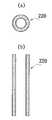
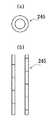
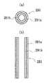
図7は、本発明にかかる一例の支持棒の断面図である。図8は、本発明にかかる他の例の支持棒の断面図である。図9は、本発明にかかる一例の支持棒と受けナットの組み合わせを示す断面図である。
【0144】
図7に示すように、本発明にかかる一例の支持棒82には、その一端に縮径部82aが設けられ、他端に突出部82bを有するストッパー部82cが設けられている。
【0145】
また、この例の支持棒82の縮径部82aには、ワッシャー83が挿入されており、支持棒82の周囲には、保護カバー84が被覆されている。
【0146】
この例では、縮径部82aに挿入されているワッシャー83がストッパー部として働き、縮径部82aの突端82dが壁支持材又は台板に挿入され、支持棒82はワッシャー83で固定される。また、突出部82bは、ストッパー部82cまで、壁支持材又は台板に挿入され、固定される。
【0147】
図8に示すように、本発明にかかる他の例の支持棒85には、両端に突出部85a及び85bを有するストッパー部85c及び85dが設けられている。支持棒85は、保護カバー86で覆われている。突出部85a及び85bは、それぞれ、ストッパー部85c及び85dまで、壁支持材又は台板に挿入され、固定される。
【0148】
図9に示すように、本発明にかかる一例の支持棒87と受けナット88の組み合わせでは、支持棒87と受けナット88とを用いる。支持棒87の一端には、縮径部87aが設けられ、支持棒87の他端には、ネジ部87bが設けられており、受けナット88はネジ部87bと螺合する。
【0149】
受けナット88には、台板89の中央部に設けられる貫通穴89aに挿入される突出部88aと、貫通穴89aの表面89bを覆う鍔部88bとが設けられている。
【0150】
受けナット88の鍔部88bは、受けナット88と螺合した支持棒87が台板89に所定量以上侵入しないようにするストッパー部として働く。
【0151】
支持棒87の周囲には、異なる材質からなる、例えば、外側がソリッドゴム層90aで、内側が発泡体層90bからなる保護カバー90が設けられる。
【0152】
【実施例】
本発明を、図面を参照して、実施例に基づいて説明する。
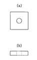
図10(a)は、参考例1にかかる壁支持材の平面図であり、図10(b)は、(a)の壁支持材の断面図である。図11(a)は、参考例2にかかる壁支持材の平面図であり、図11(b)は、(a)の壁支持材の断面図である。図12(a)は、参考例3にかかる壁支持材の平面図であり、図12(b)は、(a)の壁支持材の断面図である。図13(a)は、参考例4にかかる壁支持材の平面図であり、図13(b)は、(a)の壁支持材の断面図である。図14(a)は、参考例4にかかる壁支持材の平面図であり、図14(b)は、(a)の壁支持材の側面図である。
【0153】
図15は、参考例6にかかる間仕切り壁構造の要部垂直断面図である。図16(a)は、参考例6にかかる壁支持材の平面図であり、(b)は、(a)の壁支持材の断面図である。図17は、参考例6にかかる保護カバーの横断面図であり、(b)は、(a)の保護カバーの縦断面図である。
【0154】
図18は、参考例7にかかる間仕切り壁構造の要部垂直断面図である。図19(a)は、参考例7にかかる壁支持材の平面図であり、(b)は、(a)の壁支持材の断面図である。図20は、参考例7にかかる保護カバーの横断面図であり、(b)は、(a)の保護カバーの縦断面図である。
【0155】
図21は、参考例8にかかる間仕切り壁構造の要部垂直断面図である。図22(a)は、参考例8にかかる壁支持材の平面図であり、(b)は、(a)の壁支持材の断面図である。
【0156】
図23は、実施例2にかかる間仕切り壁構造の要部垂直断面図である。図24は、参考例9にかかる間仕切り壁構造の要部垂直断面図である。図25は、参考例9にかかる保護カバーの横断面図であり、(b)は、(a)の保護カバーの縦断面図である。
【0157】
図26は、比較例3にかかる壁構造の要部垂直断面図である。
【0158】
参考例1
図1に示すような間仕切り壁構造を施工する。
床開口部が3.7m×1.85mの床に、短辺600mm、長辺1800mm、厚み100mmのALC床版6枚を床基版2として設置する。
【0159】
上下階同位置に、間仕切り壁取付用ボルト101を、間仕切り壁長さ3.6mに450mmピッチで、床基版上、接着剤102により設置し、ボルト位置に、中央穴を有する50mm角10mm厚の、固有振動数60Hzの表1に示した壁支持材を設ける。なお、この例で用いた壁支持材の形状を、図10(a)及び(b)に示す。
【0160】
間仕切り壁4の下枠材4cをナット103で固定する。間仕切り壁4の上枠材4dは、非加硫ブチルゴム2mm厚シート104と天井板5を挟んで、天井受け桟6にビス固定する。
【0161】
次に、予じめ、間仕切り壁4が設置された床基版2に、15mm厚パーチクルボード105をDACビス固定で敷き並べ、その上に12cm厚フローリング材106をフロアーネイルで下地パーチクルボード105へ固定する。間仕切り壁4と床材3との隙間は、幅木107で塞ぐ。
【0162】
得られた間仕切り壁構造を、重量床衝撃音の測定に供試した。重量床衝撃音は、JIS−A−1418によって測定した。結果を表2に示す。
【0163】
参考例2
図2に示すような間仕切り壁構造を施工する。
参考例1と同様、ALC床版を床基板とし、パーチクルボード15mm厚をDACビスでALC床版に固定し敷き並べ、その上に12mm厚フローリング材をフロアーネイルで固定する。
【0164】
次に、間仕切り壁設置位置に墨線を打ち、間仕切り壁3.6mに、450mmピッチで55mmφの貫通孔を設ける。
【0165】
上底40mmφ、下底50mmφ、高さ25mmφの加硫ゴムと50mmφ、5mm高さのEPT発泡体を積層して、壁支持材を作製し、この壁支持材を貫通孔内に設置する。壁支持材の構成を、表1、図11(a)及び(b)に示す。
【0166】
その上から、間仕切り壁を設置し、下枠材を床材にビス固定した。次に、間仕切り壁の上枠材は、天井板を挟んで天井受け桟にビス固定するが、この際に、振動絶縁材として10倍発泡ポリエチレン2mm厚シート108を天井板15と上枠材14dとの間に介在させる。
【0167】
得られた間仕切り壁構造を重量床衝撃音の測定に供試した。得られた結果を表2に示す。
【0168】
参考例3
図3に示すような間仕切り壁構造を施工する。
床基版22をALC床版とし、床支持材28には、上下に板材29a,29bを設け、複数の制振要素30a,30c及びバネ要素30bを並列で固定した物を、接着剤109としてのウレタンコーキングで床基版22に固定する。
【0169】
床支持材28は、ALC床版の短辺方向に芯/芯600mmピッチ、長辺方向に芯/芯450mmピッチで配置した。床支持材28の上に、20mm厚のパーチクルボード110を隙間なく敷き並べ、床支持材28の上板29bにパーチクルボード110をビス固定する。
【0170】
次に、8mm厚の遮音材111、15mm厚のパーチクルボード112を敷き並べ、20mm厚のパーチクルボード110にビス固定する。次に、12mm厚のフローリング材113をフロアーネイルで固定して形成する。
【0171】
次に、間仕切り壁設置位置で、3.6m長さ、450mmピッチで、貫通孔23aを設ける。
【0172】
固有振動数130HzのSBRゴムを壁支持材27とし、その上下を板状材114a,114bで挟み、ストッパー115としてのワッシャー115a,115bを上下に設けた支持棒32を壁支持材27の上に固定し、支持棒32の上部に台板31を設け、間仕切り壁24の下枠材24cを台板31に固定する。なお、壁支持材27の構成を、表1、図11(a)及び(b)に示す。
【0173】
間仕切り壁の上枠材24dと天井板25との間には、振動絶縁材116として、2mm厚の不織布を貼り、上枠材を天井受け桟26に固定する。
【0174】
得られた間仕切り壁構造を重量床衝撃音の測定に供試した。得られた結果を表2に示す。
【0175】
参考例4
図4に示すような間仕切り壁構造41を施工する。
基本的に、参考例3の間仕切り壁構造と同様であるが、壁支持材47として、上下の板状材49a,49bの間に、4ケのゴム製制振要素50a,50cとそれらの中央に円錘状バネ要素50bを並列に設けた50mm角の壁支持材を用いる。壁支持材47の構成を、表1、図12(a)及び(b)に示す。
【0176】
この壁支持材47には、支持棒117と台板118を設ける。支持棒117には、その上下に、ストッパー119としてのワッシャー119a,119bを設ける。
【0177】
壁支持材47と支持棒117と台板118とを一体化して、貫通孔43a内に設置し、板状材49aを床基版42に接着剤120を用いて固定し、板状材49bを間仕切り壁の下枠材44cにビス固定する。
【0178】
次に、間仕切り壁の上枠材44dと天井板45との間に、振動絶縁材121としての2mm厚不織布を設け、上枠材44dを天井受け桟46にビス固定する。
【0179】
得られた間仕切り壁構造を重量床衝撃音の測定に供試した。得られた結果を表2に示す。
【0180】
参考例5
図5に示すような間仕切り壁構造61を施工する。
床基版を100mm厚のALC床版とし、床支持材68を市販の二重床支持脚とする。床支持材68には、ゴム脚122と鉄製ネジ付支持棒123と台板124とを設け、ゴム脚122には、ストッパー125としてのワッシャーを設け、台板124には、下側から受けナット126を嵌め込み、粘着剤で固定する。鉄製ネジ付支持棒123には、予じめソリッドゴムと発泡ゴムの積層パイプを保護カバー127として固着する。
【0181】
間仕切り壁の壁支持材67としては、60mm角、30mm厚の固有振動数20Hzの表1に示した壁支持材67の上下に木製の60mm角、35mm厚の板状材128a,128bを接着し、間仕切り壁36m長さ当り450mmピッチで、床基版62に、接着剤129としてのウレタンコーキングで接着固定する。なお、壁支持材67の構成を、表1、図13(a)及び(b)に示す。
【0182】
【表1】
床支持材68で、600mm幅×1800mm長さ×20mm厚のパーチクルボード130を幅方向600mmピッチ、長さ方向1800mmピッチで支持する。
【0184】
この時、床支持材68は、T字形又はパーチ長辺の各2辺で、パーチクルボード130を支持できる様にし、台板124上に突き出る受けナット126の径以上に、各パーチクルボード130を離間させる。
【0185】
パーチクルボード130上に、8mm厚の遮音材131を隙間なく敷き並べ、その上に、9mm厚のパーチクルボード131を隙間なく敷き並べ、ビス固定する。パーチクルボード132の上に、12mm厚のフローリング材132を、フロアーネイルで固定する。
【0186】
次に、間仕切り壁支持材67の上に、間仕切り壁64を設置し、下枠材64cと床材63とをビス固定し、上枠材64d上に天井65を設け、上枠材64dを天井受け桟66にビス固定する。
【0187】
得られた間仕切り壁構造を重量床衝撃音の測定に供試した。得られた結果を表2に示す。
【0188】
実施例1
参考例4の実験終了後に間仕切り壁を除去し、図6に示すようにして、壁支持材を設置した貫通孔の間に、ほぼ等分間隔で、450mm穴ピッチに対して2ケの40mmφの床貫通口を設ける。
【0189】
開口状態のままで、間仕切り壁の下枠材と壁支持材上の台板をビス固定した。次いで、間仕切り壁の上枠材の上に、2mm厚の不織布を振動絶縁材として設けて、その上に天井板を設け、上枠材を天井受け桟にビス固定する。
【0190】
得られた間仕切り壁構造を重量床衝撃音の測定に供試した。得られた結果を表2に示す。
【0191】
参考例6
図15に示すような間仕切り壁構造201を施工する。
床支持材202は、300mm角、5.5mm厚合板203の上に円錐台状の柔軟なゴム204を4個固定し、中央に座金で固定した円錐状バネ205を固定し、その上に225mm角、9mm厚の合板206を円錐台状の柔軟なゴム204に固定一体化して作製する。
【0192】
床基版207としては、約3.7mm×1.85mmの開口部を有する床に設置する、短辺600mm、長辺1800mm、厚み100mmのALC床版を用いる。
【0193】
ALC床版207には、短辺方向芯/芯600mmピッチ、長辺方向芯/芯450mmピッチで、床支持材202の合板203を90mm長さのDACビスで固定する。
【0194】
床材208としては、床支持材207の上に、909mm幅×1818mm長さ×20mm厚のパーチクルボード209を並べ、ビスで床支持材207の上板206に固定し、比重3.2、厚み6mmの450mm幅×900mm長さの遮音マット210を敷き並べ、その上に、909mm幅×1818mm長さ×9mm厚のパーチクルボード211を並べ、ビスで20mm厚パーチクルボード209に固定し、303幅×1818mm長さ×12mm厚のフローリング材212を釘止め固定して形成する。
【0195】
床施工部の長手方向に、間仕切り壁213を3.6mm設置するように、間仕切り壁213の中心相当部に墨線を打ち、芯/芯450mmピッチで50mmの貫通孔214をあける。
【0196】
壁支持材215は、図16(a)及び(b)に示す、SBR加硫ソリッドゴム216とEPT発泡ゴム体217の積層品25mm径25mm厚を使用した。図16(a)及び(b)に示すように、ゴム216には、支持棒を差し込むための差し込み孔216aを設ける。
【0197】
支持棒218は、図7に示すようなものを用いる。支持棒218は、10mm径、92mm長さの鉄製とし、下部を8mm径に縮径して、縮径部218aを設ける。縮径部218aには、ストッパー部219として25mm径のワッシャーを差し込む。
【0198】
また、支持棒218には、3mm厚で20mm径に拡径したストッパー部218bを設ける。支持棒218の縮径部218aにワッシャーを差し込む前に、図17に示すEPT発泡ゴムパイプを保護カバー220として差し込む。この支持棒218にはネジ部は設けない。
【0199】
台板221は、合板12mm厚60mm角とし、中央に9mm径の貫通穴を設け、10mm径の支持棒218の突出部218cをストッパー部218bまで圧入固定する。
【0200】
壁支持材215及び支持棒218を貫通孔に差し込み、台板221と床材208をネジ釘で固定し、間仕切り壁213の下枠材213aと台板221を木ネジで固定し、間仕切り壁213の上枠材を、天井板を挟んで、天井受け桟に木ネジで固定する。間仕切り壁213の縦枠材は、間柱と木ネジで固定する。間仕切り壁は、上下階の平面で同位置に設置して、重量床衝撃音を測定した。結果を、表3に示す。
【0201】
参考例7
図18に示すような間仕切り壁構造231を施工する。
ALC床版を床基版232とする。床基版232上の床支持材233として、300mm角9mm厚の合板を、上板234とし、4ケの円錐台状の柔軟なゴム235を接着固定し、中央に座金に固定した円錐状バネ236を合板237にビス固定し、先端に異音防止カバーをつけて、ウレタンコーキングで接着する。
【0202】
床支持材233上に、参考例1と同様に床材238を設けて、床材238に貫通孔238aを作製する。
【0203】
壁支持材240は、図19(a)及び(b)に示すものを用いる。図19に示すように、壁支持材240は、円錐台状で、上底20mm径、下底40mm径、高さ20mmのEPT/IIRソリッドゴム241とEPT/IIRブチルゴム発泡体242を40mm厚でソリッドの下面に積層した物とする。
【0204】
支持棒243は、鉄製で10mmφで、上下に台板244や壁支持材240への差し込み代243a,243bを残して、20mm径3mm厚のストッパー部243c,243dが設けてあり、それらのストッパーの間に、図20(a)及び(b)に示すような、6.6−ナイロン製の帯状物を螺旋状に巻いて成形した保護カバー245を設ける。
【0205】
台板244としては、60mm幅×90mm長さ×12mm厚合板の中央に9mm径の貫通穴244aをあけ、その中に、支持棒243を圧入して固定し、壁を支持する。
【0206】
参考例6と同様に、貫通孔238aに壁支持材240及び支持棒243を差し込み、台板244と床材238を木ネジで固定する。
【0207】
間仕切り壁245の下枠材245aと合板244の間に、振動絶縁材246として、EPT発泡体60mm幅×90mm長さ×2mm厚を設け、木ネジで下枠材245aと合板244とを固定し、間仕切り壁245の上枠材245bの全面に、60mm幅×2mm厚のEPT発泡体246を設けて、その上に、天井板247を設けて、天井受け桟248にネジ釘で固定する。
【0208】
間仕切り壁245の縦枠材と間柱の間に、EPT発泡体60mm幅、2mm厚を敷き、木ネジで固定する。得られた間仕切り壁構造231の重量床衝撃音を測定し、結果を表3に示す。
【0209】
参考例8
図21に示すような間仕切り壁構造251を施工する。
この例では、基本的には、参考例6で試験した床を使用するが、参考例6の床支持材の上下を逆転させ、床基版に接する面には合板を設けず、床材に接する面にのみ合板を設けた床支持材252を用い、更に、図22に示すような壁支持材253を用いる。
【0210】
壁支持材253では、内径9mm、外径23mmの二層構造パイプ状の内側硬度35、外側硬度50の各々のソリッドゴム254,255で、高さ23mmのものと、エチレン酢酸ビニルの20倍発泡2mm厚シート256を積層した物に、支持棒差し込み穴257を設けて用いる。
【0211】
支持棒258、台板259は、共に参考例7で用いた物を用いる。間仕切り壁260の下枠材260aと台板258は、2mm厚50mm幅の非加硫ブチルゴムシート261を挟んで木ネジで固定する。
【0212】
間仕切り壁の上枠材は、天井板を挟んで、天井受け桟に木ネジで固定する。間仕切り壁の縦枠材と間柱を木ネジで固定する。得られた間仕切り壁構造の重量床衝撃音を測定した。結果を表3に示す。
【0213】
実施例2
この例では、基本的には、参考例8で試験した床を使用するが、参考例6で使用した床支持材及び壁支持材を用いる。また、図23に示すように、床材271の貫通孔271aの間の中央に、50mm径の床貫通口272を1ケづつ計8ケ設け、開口状態のまま、間仕切り壁の下枠材を台板206に木ネジで固定する。
【0214】
間仕切り壁の上枠材は、天井板を挟んで、天井受け桟に固定し、間仕切り壁の縦枠材は、間柱に木ネジで固定する。得られた間仕切り壁構造の重量床衝撃音を測定し、結果を表3に示した。
【0215】
参考例9
図24に示すような間仕切り壁構造281を施工する。
約3.7m ×1.85m の開口部を有する床に、短辺900mm長辺1800mm厚さ150mmの金ゴム仕上RC床版を4枚を並べて、床基版282を設置する。
【0216】
その上に、参考例6で用いた床支持材202を、RC床版の短辺方向で600mmピッチ、長辺方向で450mmピッチで、RC床版と床支持材202の下板203を接着剤で固定する。
【0217】
床支持材202の上に、909mm幅×1818mm長さ×20mm厚のパーチクルボード283を並べ、ビスで床支持材202の上板206に固定し、比重3.2、厚み6mmの450mm幅×900mm長さの遮音マット284を敷き並べ、その上に、909mm幅×1818mm長さ×9mm厚のパーチクルボード285を並べてビスで20mm厚パーチクルボード283に固定する。次に、303mm幅×1818mm長さ×12mm厚のフローリング材286を釘止め固定して床材287を形成した。
【0218】
床施工部の長手方向に、3.6mの間仕切り壁288を設置できるように、間仕切り壁288の中心相当部に墨線を打ち、芯/芯450mmピッチで50mmの貫通孔287aを床材287にあける。
【0219】
壁支持材289は、参考例6と同じにし、支持棒としては、図9に示すような支持棒290を用いる。支持棒290は、鉄製で、支持棒290の上部20mm長さのみネジ部290aを設け、支持棒290の天端部に、ネジを回すためのマイナス溝がある。
【0220】
保護カバーは、図25に示すような保護カバー291を用いる。保護カバー291は、外側ソリッドゴムEPT291a/内側発泡体EPT291b積層パイプを用いる。
【0221】
保護カバー291は、支持棒290の下部のストッパー部219からネジ部290aの10mmのところまで入れた。参考例6と同様に、支持棒の下部のストッパー部219は、支持棒10mm径を8mm径に縮径して、25mm径のワッシャーを差し込んで作製する。
【0222】
台板292は、60mm角12mm厚の合板とし、中央に13.5径の貫通穴を設けて、外径15mm受け部2mm厚30mm径の受けナット293を圧入固定する。
【0223】
受けナット293は、支持棒290のネジ部290aと螺合し、床面との隙間を2mmにして、木ネジで床材287に固定する。
【0224】
間仕切り壁288の下枠材288aと台板292を、2mm厚ゴムシート294を挟んで、木ネジで固定し、間仕切り壁288の上枠材288bに60mm幅2mm厚のポリエチレン発泡体295を取り付け、天井板296を挟んで、天井受け桟296に木ネジで固定する。
【0225】
間仕切り壁288の縦枠材と間柱の間に、60mm幅×2mm厚ポリエチレン発泡体を挟んで、縦枠材と間柱とを木ネジで固定する。得られた間仕切り壁構造の重量衝撃音を測定し、結果を表3に示した。
【0226】
参考例10
参考例9の床基版と床材を使用するが、壁支持材が参考例7と同じで、参考例9と同じ支持棒及び受けナット付台板を使用して、床材の貫通孔に差し込み、台板と床材の隙間が約2mmとなるように高さ調整ネジで調整し、台板と床材を木ネジで固定する。
【0227】
次いで、間仕切り壁の下枠材と台板を木ネジで固定し、間仕切り壁の上枠材を天井板と天井受け桟にネジ釘で固定する。間仕切り壁の縦枠材と間柱とを木ネジで固定する。得られた間仕切り壁構造の重量床衝撃音を測定し、表3に示した。
【0228】
比較例1
参考例2のように、直貼床をALC床版上に形成し、貫通孔及び壁支持材を設けないで、直接、間仕切り壁の下枠材を直貼床にビス固定し、間仕切り壁の上枠材を、天井板を挟んだ状態で、天井受け桟にビス固定して、壁構造を施工し、この壁構造を重量床衝撃音の測定に供試した。結果を表2に示す。
【0229】
比較例2
比較例1の実験終了後に、比較例1に用いた間仕切り壁を上下階共に取り外して供試した。重量床衝撃音の測定結果を、表2に示した。
【0230】
【表2】
比較例3
図26に示すような壁構造301を施工する。
参考例6の床支持材202で支えられた、貫通孔を明ける前の床208に、間仕切り壁302の下枠材302aを直接床208にビスで固定し、間仕切り壁301の上枠材を天井板と天井受け桟に固定し、間仕切り壁301縦枠を間柱に固定した。得られた壁構造の重量床衝撃音を測定し、表3に示した。
【0232】
【表3】
参考例1は、ALC床基版上に、予じめ壁支持材で支持した間仕切り壁を設けた壁先行工法に於ける、間仕切り壁の支持をした例である。比較例2は、ALC床基版上に床を施工し床上に間仕切り壁を設けていない例である。比較例1は、ALC床基版に床を施工し、床上に壁支持材を設けずに、間仕切り壁を設けた例である。
【0234】
表2に示すように、比較例1の壁構造は、比較例2のものと比べ、63Hzで4dB、125Hzで5dB、間仕切り壁を設ける事で悪化している。参考例1の間仕切り壁構造は、比較例2のものと比べ、ほとんど63Hz、125Hzで変化していない。つまり、間仕切り壁による悪化を防止している事が判る。
【0235】
参考例2の間仕切り壁構造は、ALC床基版上に床を施工し、床に貫通穴を設けて、床基版上に壁支持材を設けて、間仕切り壁を支持した例である。この例では、63Hz、125Hzでの悪化は認められず、比較例2とほぼ同等の結果となっている。つまり、間仕切り壁による悪化は見られない。
【0236】
参考例5の間仕切り壁構造は、ALC床基版上に、市販の二重床と遮音材を施工し、間仕切り壁直下の床下をの緩衝材で支持した例である。比較例2の壁構造と比べ、63Hz、125Hz共3dBの改善効果が見られた。
【0237】
参考例3の間仕切り壁構造は、AC床基板上に上下板材間に、複数の制振要素及びバネ要素を並列で設けた床支持材上に、床を形成し、床に貫通孔を設けて、間仕切り壁の壁支持材を、固有振動数130Hzとした例である。この例のものは、比較例2と比べ、63Hzで8dB、125Hzで3dB改善できている。
【0238】
参考例4の間仕切り壁構造は、床支持材、間仕切り壁支持材を共に上下板材間に複数の制振要素及びバネ要素を並列で設けた物で支持した例である。比較例2と比べて、63Hzで9dB、125Hzで6dBと非常に大きく改善できている。
【0239】
実施例1の間仕切り壁構造は、参考例4と同じ床支持、間仕切り壁支持であるが、壁支持材設置間に床貫通口を各2ケ所づつ設け、開口状態のままで、間仕切り壁を取付けた例である。参考例4よりもさらに改善でき、比較例2と比べ、63Hzで11dB、125Hzで10dB改善され、非常に大きな改善効果がある事が判る。
【0240】
また、施工面では、参考例3の間仕切り壁構造では、支持棒が保護カバーで覆われているので、台板と支持棒又は支持棒と壁支持材の螺合部で、保護カバーが螺合部を押し、螺合部のガタツキ、ユルミが防止されて、異音の発生がなくなった。また、螺合部の接着剤による固着作業は不要であった。
【0241】
参考例6の間仕切り構造は、ALC床版を床基版とし、床基版上に床支持材を固定し、その上にパーチクルボード、遮音材、パーチクルボードを積層固定し、フローリング材を釘止めして、床を作り、間仕切り壁設置部に貫通孔を設け、間仕切り壁の壁支持材を床に固定し、台板に間仕切り壁の下枠材を固定し、間仕切り壁の上枠材を天井板とともに天井受け桟に固定し、間仕切り壁の縦枠材を間柱に固定して、間仕切り壁を設置した例である。
【0242】
参考例6では、施工時の高さ調整は不要であった。同一床構成の比較例3と比べ、明らかに良くなっており、間仕切り壁での悪影響は解消されて、目標のLH −55はクリアーできている。比較例3より従来の乾式二重床と衝撃緩衝パットを使用した床は重量衝撃音の低減で明らかに相違することが判る。
【0243】
参考例7は、参考例6の床と同一構成で壁支持材、支持棒、台板が1ケ当りの面積が1.5倍になり、間仕切壁の枠と台板、天井受け桟、間柱との間にEPT発泡体を振動絶縁材として使った例である。施工時の高さ調整は、不要であった。参考例6よりも少し良い結果が得られ、LH −55をクリアーしている。
【0244】
参考例8では、参考例6及び7と比べ、床を支持する床支持材を、下板のないタイプとした点と、壁支持材が硬度の異なる二層構造パイプとEVA発泡体の積層品である点と、間仕切り壁との振動絶縁が下枠材と台板のみとなった点が相違している。この例では、施工時の高さ調整は不要であった。この場合も低周波音の低減が大きく、間仕切り壁の悪影響がないことが判る。また、2dB許容ではあるが、LH −55をクリアーしている。
【0245】
実施例2の間仕切り壁構造は、参考例6と相違して、床の貫通孔穴を各壁支持材の設置部の間に各1個計8個開口のまま設けた例である。この例では、施工時の高さ調整は不要であった。参考例6よりも更に2dB良くなり、工夫次第では、LH −50も可能性があるレベルになった。
【0246】
参考例9の間仕切り壁構造は、床基版を150mm厚RC床版とした例である。床支持材や床構成は参考例6と同じである。壁支持材は参考例6と同じであるが、支持棒上部には高さ微調整のネジを設け、台板は受ナットを設け、保護カバーにより螺合部のガタツキゆるみは無く、螺合部固着用接着剤は使う必要がなかった。間仕切り壁の下枠材と台板との間に、EPT発泡体を振動絶縁材として設け、間仕切り壁の上枠材と天井受け桟、間仕切り壁の縦枠材と間柱の間に発泡ポリエチレンを振動絶縁材として設けた例である。また、高さ調整は、8ケ所中1ケ所で行った。
【0247】
参考例9は、床基版自体の性能もよいこともあって、LH −50をクリアーしている。間仕切り壁による悪影響は受けていないと判断できる。
【0248】
参考例10は、参考例9と同じ床基版に同じ床が形成され、壁支持材は参考例7と同じであり、支持棒、台板は参考例9と同じである。保護カバーにより螺合部のガタツキ、ゆるみはなく、接着剤による固着は不要であった。また、間仕切り壁の各枠との振動絶縁は行っていない。高さ調整は不要であった。
【0249】
その結果、参考例10では、重量床緩衝音も参考例9と同様LH −50をクリアーしている。間仕切り壁による悪影響は受けていないと判断できる。
【0250】
以上のように、本発明の間仕切り壁構造は、床工法にとらわれる事なく、間仕切り壁が、床基版本来の防音性を悪化させる事がない事が判る。
【0251】
また、本発明の間仕切り壁構造は、床支持、壁支持を板材に複数の制振要素又はバネ要素を並列で設けて支持する事で、間仕切壁を設置しても、重量床衝撃音を悪化させることなく、却って大幅に改善できる。
【0252】
さらに、本発明の間仕切り壁構造は、床貫通口を、間仕切り壁の下部に開口状態のままで設ける事で、重量床衝撃音をより一層改善できる。
【0253】
本発明の間仕切り壁構造は、住居空間を仕切る間仕切り壁構造として、広く使用できる。
【0254】
【発明の効果】
本発明の間仕切り壁構造によれば、床基版と間仕切り壁の下枠材との間又は間仕切り壁の直下の床材と床基版との間に、10〜150Hzの固有振動数を示す所定の壁支持材を介在させ、所定の貫通孔及び貫通孔の間の床貫通開口を設けているので、間仕切り壁の重量床衝撃音に与える悪影響が抑えられ、重量床衝撃音が著しく低減する。
【図面の簡単な説明】
【図1】本発明にかかる1例の間仕切り壁構造の要部垂直断面図である。
【図2】本発明にかかる他の例の間仕切り壁構造の要部垂直断面図である。
【図3】本発明にかかる更に他の例の間仕切り壁構造の要部垂直断面図である。
【図4】本発明にかかる更に他の例の間仕切り壁構造の要部垂直断面図である。
【図5】本発明にかかる更に他の例の間仕切り壁構造の要部垂直断面図である。
【図6】本発明の1例の間仕切り壁構造で用いた床材の平面図である。
【図7】本発明にかかる一例の支持棒の断面図である。
【図8】本発明にかかる他の例の支持棒の断面図である。
【図9】本発明にかかる一例の支持棒と受けナットの組み合わせを示す断面図である。
【図10】(a)は、参考例1にかかる壁支持材の平面図であり、(b)は、(a)の壁支持材の断面図である。
【図11】(a)は、参考例2にかかる壁支持材の平面図であり、(b)は、(a)の壁支持材の断面図である。
【図12】(a)は、参考例3にかかる壁支持材の平面図であり、(b)は、(a)の壁支持材の断面図である。
【図13】(a)は、参考例4にかかる壁支持材の平面図であり、(b)は、(a)の壁支持材の断面図である。
【図14】(a)は、参考例4にかかる壁支持材の平面図であり、(b)は、(a)の壁支持材の側面図である。
【図15】参考例6にかかる間仕切り壁構造の要部垂直断面図である。
【図16】(a)は、参考例6にかかる壁支持材の平面図であり、(b)は、(a)の壁支持材の断面図である。
【図17】参考例6にかかる保護カバーの横断面図であり、(b)は、(a)の保護カバーの縦断面図である。
【図18】参考例7にかかる間仕切り壁構造の要部垂直断面図である。
【図19】参考例7にかかる壁支持材の平面図であり、(b)は、(a)の壁支持材の断面図である。
【図20】参考例7にかかる保護カバーの横断面図であり、(b)は、(a)の保護カバーの縦断面図である。
【図21】参考例8にかかる間仕切り壁構造の要部垂直断面図である。
【図22】(a)は、参考例8にかかる壁支持材の平面図であり、(b)は、(a)の壁支持材の断面図である。
【図23】実施例2にかかる間仕切り壁構造の要部垂直断面図である。
【図24】参考例9にかかる間仕切り壁構造の要部垂直断面図である。
【図25】参考例9にかかる保護カバーの横断面図であり、(b)は、(a)の保護カバーの縦断面図である。
【図26】比較例3にかかる壁構造の要部垂直断面図である。[0001]
BACKGROUND OF THE INVENTION
The present invention relates to a partition wall structure in which a partition wall is fixedly supported on a floor of a building and a space on the floor is partitioned.
[0002]
[Prior art]
The partition wall is installed by setting bolts on the floor base plate and fixing the partition wall lower frame with nuts thereto, or by previously forming a floor and fixing the partition wall lower frame to the floor. .
[0003]
[Problems to be solved by the invention]
The present inventor has found that when a building is subjected to a floor impact, particularly the heavy floor impact sound is worse than the value of the heavy floor impact sound indicated by the floor base plate alone.
[0004]
The present inventor has also found that the tendency appears strongly in flexible structures such as detached houses and low-rise apartments.
[0005]
According to the inventor's research, none of the above-described partition wall fixing methods has been able to prevent deterioration of heavy floor impact sound due to the partition wall.
[0006]
An object of the present invention is to obtain a partition wall structure in which heavy floor impact noise is significantly reduced.
It is another object of the present invention to obtain a partition wall structure that is easy to adjust the height of the partition wall, prevents displacement after the height adjustment, and prevents noise due to rattling or loosening.
[0007]
[Means for Solving the Problems]
The present invention is a partition wall structure comprising a floor base plate, a floor material on the floor base plate, a partition wall, a ceiling plate, and a ceiling plate receiving bar, wherein the floor material ispluralHas a through hole,The through holes are provided apart from each other in the length direction of the partition wall, a floor through opening is provided between the through holes, and the lower end portion of the partition wall is the It is provided on the floor material so as to cover the through hole and the floor through opening,The partition wall has a pair of wall plates and a lower frame member and an upper frame member provided between the wall plates, and has a natural frequency of 10 to 150 Hz in at least a part of the through hole. A wall support is provided, and the wall support is made of at least one elastic body selected from the group consisting of a rubber elastic body, a plastic elastic body, and a spring elastic body, and the wall support material is the floor base. Supported by a plate, the wall support material supports the lower frame material, the ceiling plate is provided on the upper frame material, and the ceiling receiving bar is provided on the ceiling plate. The upper frame member is fixed to the ceiling plate receiving bar, and relates to a partition wall structure.
[0008]
The present inventionThen,The plurality of through holes are provided apart from each other in the length direction of the partition wall, and a lower end portion of the partition wall is provided on the floor material so as to cover each through hole. In the present invention, a floor through opening is provided between the through holes..
[0009]
The present inventor examined various partition wall structures in order to suppress the adverse effect of the partition wall on the heavy floor impact sound and maintain the performance of the original floor base plate.
[0010]
As a result of many experiments, the inventor intervenes a predetermined wall support material between the floor base plate and the lower frame material of the partition wall or between the floor material immediately below the partition wall and the floor base plate, It has been found that the heavy floor impact sound is remarkably reduced by setting the natural frequency of the wall support material to 10 to 150 Hz.
[0011]
Further, the present inventor has found that if the adverse effect of the partition wall is eliminated in the flexible structure building, the adverse effect of the partition wall can be eliminated even in the rigid structure.
[0012]
The present invention is based on the fact that the present inventor elucidates the exacerbation of heavy floor impact sound due to the adverse effect of the partition wall and maintains the original soundproof performance of the floor by eliminating the adverse effect of the partition wall. .
[0013]
According to the present invention, the predetermined wall support material exhibiting a natural frequency of 10 to 150 Hz between the floor base plate and the lower frame material of the partition wall or between the floor material immediately below the partition wall and the floor base plate. Therefore, the adverse effect of the partition wall on the heavy floor impact sound is suppressed, and the heavy floor impact sound is significantly reduced.
[0014]
The present invention relates to a partition wall support structure and a support method that do not adversely affect heavy floor impact sound, and the field of use thereof covers all buildings.
[0015]
DETAILED DESCRIPTION OF THE INVENTION
An embodiment of the present invention will be described.
Hereinafter, the components of the present invention will be described and the operation thereof will be described.
The floor base plate as used in the present invention includes the floor frame itself. In the case of high-rise apartments, the floor frame is a general RC floor slab, void slab, waffle slab. A wooden floor panel combining a joist and a board material can be exemplified.
[0016]
Middle- and high-rise apartment buildings are generally RC structures, and are slabs that inevitably cause unevenness compared to factory-produced floor slabs because they hold the concrete placed on-site.
[0017]
Such a floor base plate has a relatively large unevenness when, for example, the surface of the cast-in-place concrete is pressed down with a hammer, but if the floor thickness is sufficient, generally it will be a heavy floor impact sound. It shows good performance.
[0018]
In addition, such a floor base plate has a certain number of floor base plates that are produced in the factory, so that there is an advantage that height adjustment is not necessary particularly in a double floor or the like. However, ALC floor slabs, PC floor slabs, extruded cement floor slabs, wooden floor panels, and the like are lighter than RC floor slabs, and therefore tend to be inferior to heavy floor impact sounds.
[0019]
The floor material according to the present invention may be provided directly on the floor base plate, or may be provided with a floor support material interposed in the floor base plate. Such floor materials include floor foundations, floor finishing materials, and the like, and can be formed by laminating various plate-like materials containing these materials.
[0020]
The floor base material may be a combination of particle board, plywood, sound insulation sheet, gypsum board, iron plate, etc., and integrated with screws or adhesive to increase the bending rigidity. The flooring material is formed by integrating a floor finishing material with a screw, a nail, an adhesive or the like on a floor base material. Any material may be used as long as it is generally used for flooring.
[0021]
The floor finish material has almost no relation to the heavy floor impact sound, and the light floor impact sound can be sufficiently reduced by the floor support material or the wall support material according to the present invention, and it is not particularly necessary to use a soundproof specification.
[0022]
The heavy floor impact sound depends on the performance of the floor base plate body, but the floor floor material floated on the floor base plate with a floor support material, like the double floor, slightly improves the heavy floor impact sound. Tend to be. On the other hand, the tendency of the heavy floor impact sound to deteriorate when the partition wall is installed is more greatly influenced by the floor finishing material.
[0023]
When the wall support material according to the present invention is provided between the floor base plate and the lower frame of the partition wall, the floor material is provided with a through hole.
[0024]
Such a through hole can be formed in a groove shape with a width that allows the lower end of the partition wall to be inserted. Moreover, when fixing the lower end part of a partition wall on a flooring, several holes which are covered with the lower end part of a partition wall can be provided mutually spaced apart in the length direction of the partition wall.
[0025]
When the wall support material according to the present invention is installed in at least a part of the through hole of the floor material and the partition wall is supported by the floor material, the through hole needs to be smaller than the thickness of the partition wall. .
[0026]
In the present invention, in the double floor, a floor through-hole can be provided between the through-holes in addition to the through-hole in which the wall support material is provided.
[0027]
Such a floor through-hole can improve the heavy floor impact sound and improve the deterioration of the heavy floor impact sound due to the partition wall.
[0028]
By providing a floor through opening between the through hole with the wall support material and the through hole, the air can escape from the underfloor space when a heavy floor impact is received. Can be improved. In such a case, particularly problematic low frequency sound of 63 Hz or 125 Hz can be effectively reduced.
[0029]
At this time, if there is resistance in leaving the openings open, cover the openings with a breathable object such as a net-like material to prevent heavy floor impact sound even if the insects are prevented from moving under the floor. The reduction effect does not change.
[0030]
The shape and dimensions of the floor through-hole are not particularly limited and may be the same as the through-hole, but the opening is smaller than the partition wall thickness, preferably within the width of the lower frame material, and the number of openings is also It is better to leave 1 to 3 between the wall supports. This is because if the floor through-hole is provided in such a state, the heavy floor impact sound can be efficiently reduced without impairing the flooring material strength.
[0031]
Further, the opening area of the floor through-hole is preferably 10 mm or more. If it is this magnitude | size, the noise by an air flow will not generate | occur | produce.
[0032]
Furthermore, since it is better to disperse the openings of the floor through-holes in a wider part, it is preferable that the floor through-holes are scattered not only at a part of the lower part of the partition wall but also over the entire length.
[0033]
Note that if the floor through-hole is too large or the number of holes is too large, not only will it become a partition defect, but it will also be liable to sink due to the load on the partition wall.
[0034]
The partition wall according to the present invention includes a pair of wall plates and a lower frame member and an upper frame member provided between these wall plates. In this invention, if it is this partition wall, the thing of a various material can be used.
[0035]
The partition wall that partitions the space above the floor may be a panel-like object in which a frame is made of a vertical frame material in addition to the upper and lower frame materials, and a plate material such as a gypsum board is fixed to both sides.
[0036]
In the present invention, the partition wall fixes a wall support member, which will be described later, to the lower frame member, and fixes the ceiling receiving bar with the ceiling plate sandwiched between the upper frame member. The vertical frame member of the partition wall can be fixed to a wall column or a column.
[0037]
The lower frame material of the partition wall according to the present invention may be directly supported by a wall support material, or may be directly supported by a base plate or the like provided on the wall support material. You may support by the flooring on a support material.
[0038]
In this invention, a base plate can be provided in a wall support material, a base plate and a flooring can be fixed, and a base plate and the lower frame material of a partition wall can be fixedly supported.
[0039]
In the present invention, the wall plate of the partition wall is provided with a gap between the floor material and it is necessary to pay attention to the construction so that the vibration of the floor is not directly input to the wall plate of the partition wall. If the gap between the partition walls is covered with a skirting board, the aesthetic problem can be solved.
[0040]
A ceiling plate is provided on the upper frame member of the partition wall according to the present invention, and a ceiling receiving bar is provided on the ceiling plate. The upper frame material of the partition wall is fixed to the ceiling receiving bar.
[0041]
In the present invention, the vibration insulating material is provided in at least one place between the upper frame material of the partition wall and the ceiling plate, between the lower frame material of the partition wall and the base plate, and between the wall support material and the floor base plate. By providing, the noise reduction effect can be further enhanced.
[0042]
Such a vibration insulating material is not particularly limited, and a rubber or plastic solid, a foam, or a combination thereof may be used. In addition, a non-woven fabric, a fibrous material such as felt is also used as a suitable example. .
[0043]
Next, the wall support material which supports the partition wall concerning this invention is demonstrated.
The wall support material according to the present invention is installed between the floor base plate and the lower frame of the partition wall or between the floor material immediately below the partition wall and the floor base plate. Such a wall support member has a natural frequency of 10 to 150 Hz and is made of at least one elastic body selected from the group consisting of a rubber elastic body and a spring elastic body.
[0044]
In the present invention, such a wall support member suppresses an adverse effect on the heavy floor impact sound of the partition wall, and remarkably reduces the heavy floor impact sound.
[0045]
When the natural frequency of the wall supporting material is less than 10 Hz, the amount of improvement at 125 Hz is insufficient and the amount of displacement becomes large, which is not preferable. Conversely, when the natural frequency exceeds 150 Hz, the improvement amount of 63 Hz is insufficient.
[0046]
Such a wall support material has a noise of 250 Hz or more by combining at least one material selected from the group consisting of hard rubber having a rubber hardness of 20 (JIS-K-6253) or less, soft foam, and fibrous material. Not only is it effective for reduction, it also becomes easy to compress in advance, and there is an effect that height adjustment is unnecessary, which helps to simplify the construction and also helps to prevent floor noise.
[0047]
The wall support member is a single or combined use of a rubber elastic body using rubber, a plastic elastic body, a metal spring, an air spring, a liquid sealing spring, or the like.
[0048]
In this invention, various rubber | gum can be used as a solid, a foam, or those composites as a rubber elastic body individually or in combination. As rubber, NR, IR, SBR, NBR, BR, CR, 11R, EPT, polynorbornene rubber, urethane rubber, polysulfide rubber, chlorosulfonated polyethylene, chlorinated polyethylene, epichlorohydrin rubber, acrylic rubber, silicone rubber, Examples thereof include rubbers such as fluorine rubber and various recycled rubbers.
[0049]
In the present invention, a rubber-like substance can be used as the rubber of the rubber elastic body. Such rubber-like substances include polystyrene-based thermoplastic elastomer (hereinafter abbreviated as TPE) in which the hard segment is styrene, the soft segment is polybutadiene, polyisoprene, and hydrogenated polybutadiene, and the hard segment is polyethylene or polypropylene. Polyolefin TPE with ethylene propylene copolymer rubber, polyvinyl chloride TPE with hard segment and soft segment polyvinyl chloride, polyurethane segment with hard segment, polyurethane segment soft segment with polyester or polyester TPE, hard segment with polyamide, soft Polyamide-based TPE with a polyether or polyester segment, hard segment with syndiotactic-1,2-butadiene, soft A polymer having 2 or more terminal reactive groups per molecule in the main chain skeleton such as polybutadiene, chloroprene, isoprene, styrene butadiene, acrylonitrile butadiene, etc. A rubber obtained by curing a compound having reactivity with the terminal reactive group can be exemplified.
[0050]
When the rubber according to the present invention is used in combination with rubber powder or polymer powder, the dynamic characteristics of the rubber can be improved, which is advantageous in terms of cost.
[0051]
The plastic elastic body according to the present invention is roughly classified into a thermoplastic resin, a thermosetting resin, and an engineering resin. Examples of the thermoplastic resin include polyethylene, polypropylene, poly-4-methylponten-1, ionomer, vinyl chloride, poly Examples thereof include vinylidene chloride, polystyrene, acrylonitrile-styrene copolymer, a mixture of polybutadiene to acrylonitrile-styrene copolymer (ABS resin), methacrylic resin, polyvinyl alcohol, ethylene vinyl acetate copolymer, and cellulose acetate plastic.
[0052]
Examples of the thermosetting resin include phenol resin, urea / melamine resin, epoxy resin, polyurethane resin, unsaturated polyester resin, and silicon resin.
[0053]
Examples of the engineering resin include polyamide resin, polyacetal resin, polycarbonate resin, polyphenylene ether, thermoplastic polyester resin, polytetrafluoroethylene, polysulfone, polyetherimide, polyethersulfone, polyetherketone, polyamideimide, and polyimide.
[0054]
Examples of the air spring include a combination of a film enclosing air and a room temperature reactive liquid rubber, and air-sealed rubber. Liquid encapsulated rubber refers to rubber in which water, higher alcohol, or the like is encapsulated in rubber, and has an effect of reducing the natural frequency together with an air spring.
[0055]
Examples of the metal spring include a coil spring, a disc spring, a lap spring, a spring steel, and the like that use rubber characteristics such as spring steel by partially providing rubber or plastic.
[0056]
The rubbers, metal springs, air springs, liquid-enclosed springs, etc. are used alone or in combination, and linear spring characteristics, progressive spring characteristics, progressive spring characteristics, constant load spring characteristics, etc. are used as appropriate and buffered together. By adjusting the characteristics and the amount of displacement and setting the natural frequency to 10 to 150 Hz, it is possible to prevent the heavy floor impact sound from being deteriorated by the partition wall.
[0057]
Metal springs, in particular, have the advantage that they are not easily affected by linearity and temperature changes, but they have the disadvantage that there are few damping elements. Special characteristics can be imparted.
[0058]
Natural frequency (f0) Is usually set to 1/3 of the external force frequency (f), so f / f0≒ 3. For the wall support material, obtain the minimum load value based on the partition wall weight, the number of wall support materials that support it, and the set pressure-receiving area per unit, and the floor load setting value and partition wall load per unit. The static spring constant may be obtained by using the sum of the values as the maximum load value, and the gradient of the diagonal line may be used as the dynamic coefficient from the hysteresis curve at that time. Further, the vibration transmissibility (τ) is expressed by the following equation when the loss coefficient is η.
[Expression 1]
Here, as the loss factor is larger, the resonance peak is suppressed, but the vibration transfer characteristic in the vibration isolation region is deteriorated, so that a loss factor of 0.05 ≦ η ≦ 0.5 is good. If the loss factor is less than 0.05, the damping performance of the cushioning material itself is insufficient and braking damping becomes slow. Therefore, when the loss factor exceeds 0.5, the vibration transmission characteristics deteriorate as described above. Therefore, it is not preferable.
[0060]
It is not necessary for the wall support material to set all the lower portions of the partition walls to the same natural frequency, and it is also possible to independently support the wall support materials having a plurality of natural frequencies. Moreover, this wall support material can be used by applying compressive stress from the beginning by fixing to a floor.
[0061]
In addition, when a plate-like material is provided on at least one of the upper and lower sides of the wall support material and a plurality of vibration damping and spring elements are fixed in parallel to the plate-like material, the wall support material per one is used. The contact area to the floor base plate can be increased, and the effect of dispersing impact force and partition wall load can be increased. In this case, not only the deterioration of the heavy floor impact sound can be suppressed but also improved.
[0062]
In addition, the wall support material provided with plate-like members on the top and bottom is particularly excellent in the non-land absorbing effect of the floor base plate, and on the side in contact with the floor base plate, a rubber or polymer sheet or a foam thereof. By laminating sheets, the effect of absorbing unevenness is further improved and the effect of preventing floor noise can be exhibited. In addition, when the floor base plate is mortar finish or concrete, a moisture-proof effect by the plate-like material can be expected.
[0063]
In the wall support material according to the present invention, a plurality of floor support materials are provided on a floor base plate, the respective floor support materials are separated from each other, and the floor material is supported by each floor support material. Can be used for heavy beds.
[0064]
As the floor support material for supporting the floor material, various materials such as a floor support leg including a rubber pedestal, a column, and a base plate can be used, but the same material as the wall support material according to the present invention is used. be able to.
[0065]
Usually, the double floor has a high height on both the floor base plate and the bottom surface of the floor material, so that a column can be provided above or below the floor support material or above and below it, and the height can be adjusted by this column. .
[0066]
The support is covered with a protective cover made by laminating rubber, a polymer sheet, or a foamed material thereof to absorb unevenness, prevent floor noise and prevent moisture.
[0067]
The support can be made of wood, metal, plastic, etc., and the contact surface with the floor support material is preferably the same size as or slightly larger than the pressing surface of the floor support material.
[0068]
The floor support material that can improve the weight impact sound is preferably provided with a plate-like material on at least one of the upper and lower sides, and a plurality of vibration damping and spring elements fixed to the plate-like material in parallel.
[0069]
Such a floor support material receives an impact with a relatively large plate-like material area within one floor support material, and the impact force is distributed and absorbed by a plurality of damping elements or spring elements under the plate-like material. Therefore, the impact force is greatly attenuated when it is transmitted to the floor base plate, and as a result, the heavy floor impact sound can be greatly improved.
[0070]
The vibration damping element and spring element are a combination of various types of rubber sods, foams, and metal springs, and in the process of being displaced and restored upon impact, the effect of each damping element and spring element It is desirable to use
[0071]
In the floor support material according to the present invention, the portion of the floor support material that comes into contact with the floor base plate is preferably a rubber leg rather than a plastic leg for reducing heavy floor impact sound.
[0072]
In order to construct a double floor according to the present invention, the partition wall can be installed after the floor material has been applied to the entire surface by the floor advance construction method, and after the partition wall is supported by the wall support material by the floor follow-up method. You may install flooring.
[0073]
In the case of the floor advance method, the installation position of the partition wall on the floor material is determined in advance with a black line.
[0074]
The wall support material according to the present invention is provided with a through-hole in some place or in the form of a dot in the floor material portion at the partition wall installation position so as to support the partition wall from below the through-hole.
[0075]
In the same manner as the floor support material, the wall support material according to the present invention supports the lower frame material or is supported by the floor base plate between the wall support material and the lower frame material or floor base plate of the partition wall. A plate and a support bar that supports or is supported by the base plate can be provided. Such a support bar adjusts the height between the wall support and the base plate.
[0076]
The base plate is not particularly limited as long as it is a material that can be fixed to the lower frame material of the floor or the partition wall with screws, nails, adhesive, or the like. Examples of suitable materials for the base plate include a wooden board such as a particle board and a plywood board, and a plastic board metal board.
[0077]
In addition, the base plate may be equal to or slightly smaller than the partition wall lower frame width, and the planar shape may be a square, but in consideration of the weight of the partition wall, the strength of the ceiling receiving bar, etc., it is rectangular and has a wide area. You may receive it at.
[0078]
With double floors, if you use ALC floor slabs, PC floor slabs, extruded hollow cement, floor slabs, wood floor panels, etc., which are factory-produced products of a certain size, you do not need to adjust the height completely. Even in the case of floor base plates with relatively large unevenness, such as gold-plated surfaces of cast-in-place concrete, height adjustment is unnecessary in most cases. In particular, in the case where the floor base plate is cast-in-place concrete, if the floor support material is provided with a height adjusting function, the unevenness accuracy of the floor base plate is not much questioned.
[0079]
For this reason, it is desirable to provide the wall support material with a support bar having a thread groove or a thread for adjusting the height and a plywood with a receiving nut having a thread or a thread groove to be screwed with the support bar.
[0080]
In the present invention, it is desirable that the support rod is covered with a protective cover having such a thickness that the screwing portion is compressed to prevent the screwing portion from rattling and loosening due to vibration.
[0081]
That is, in the double floor, the number of floor and wall supports increases. For this reason, when the height of the support member is adjusted by screwing, a loose design in which the screwing part can be easily turned is preferable in order to shorten the adjustment work time and facilitate height adjustment.
[0082]
However, after the operation, if the screwed portion is not fixed with an adhesive, a rattling sound or looseness will occur due to vibrations, resulting in inadequate height adjustment and problems such as floor noise.
[0083]
Therefore, it is preferable that the screwed portion is fixed by an adhesive. However, since there are a large number of screwing portions, forgetting to stick and troublesome work are problematic.
[0084]
In the protective cover of the support rod according to the present invention, since the compressive force of the protective cover acts on the threaded portion, rattling and loosening do not occur.
[0085]
The protective cover according to the present invention may be formed of a solid material such as rubber or plastic, a foamed material, or a combination thereof, and may have a shape that surrounds the outer periphery of the support bar.
[0086]
Such a protective cover is made to be slightly larger or smaller according to the preset height, so that the force that pushes up the nut part and the wall support works, and the protective cover is compressed to prevent rattling and loosening of the screwing part. Can do. Other effects of the protective cover include prevention of floor noise due to rubbing between the through hole and the support rod, and rust prevention effect of the support rod.
[0087]
Such a protective cover may have a threaded portion depending on the floor base plate, and it is possible to prevent rattling of the threaded portion at this time.
[0088]
The protective cover according to the present invention may be in the form of a pipe or a double structure of a pipe-shaped object, or a spirally wound belt-shaped object, or a spirally-wound cylinder Alternatively, it may be obtained by coating, dipping, or the like.
[0089]
In the present invention, the wall support material is formed from at least one substance selected from the group consisting of a solid or foam of rubber or plastic, and the wall support material and the lower frame material or floor base plate of the partition wall. In the case where a base plate that supports the lower frame material or is supported by the floor base plate and a support bar that supports the base plate or is supported by the base plate, a reduced diameter portion is provided at one or both ends of the support rod. , And the reduced diameter portion can be inserted into and fixed to the wall support member or the base plate to adjust the height between the wall support member and the base plate.
[0090]
Further, in the present invention, a stopper portion having a diameter larger than the diameter of the support rod is provided at one end or both ends of the support rod, and the support rod is inserted and fixed to the wall support material or the base plate up to the stopper portion. The height between the wall support and the base plate can be adjusted.
[0091]
In the partition wall structure constituted by such a wall support material, when the partition wall is supported by the wall support material, the height adjustment becomes easy, and the height adjustment can be performed with a fine adjustment level.
[0092]
In the support of the partition wall, after fine adjustment of the height, rattling of the screwed portion between the wall support material and the support rod or the support rod and the base plate is prevented, and loosening of the screwed portion due to vibration can be prevented. There is no need to fix the screwed portion with an adhesive.
[0093]
In the case of a concrete slab where the floor slab is cast in the field, the surface is manually finished with gold, so some unevenness is inevitable. Also, in the case of floor advancement, a through hole is provided in the flooring material and the wall support material is brought into contact with the floor base plate. . In such a case, the wall support material naturally has a small contact area with the floor base plate, and there is a limit to non-land absorption.
[0094]
Therefore, in such a case, it is desirable to use a type of wall support material that can be finely adjusted in height assuming that a part of the partition wall cannot be completely absorbed in supporting the partition wall. Even in this case, since the wall support material has a non-land absorbing function, the height adjustment is fine adjustment, and since the wall support material is installed only at the lower part of the partition wall, the adjustment work can be greatly reduced. .
[0095]
As the wall support material used in such a case, rubber, plastic solid or foam can be suitably used, and various materials including those described above can be used as the material of rubber or plastic.
[0096]
Moreover, the support rod used in such a case can use various things, if it is fixed so that it may not sink more than a fixed amount in a wall support material or a base plate. As such a support rod, a support rod surrounded by a protective cover can be used.
[0097]
As described above, the protective cover can be made of the same material, shape, and the like as described above, and can prevent flooring and the like caused by rubbing of the support rod or the like in the through hole.
[0098]
In the present invention, in order to fix the wall support material and the support rod or between the support rod and the base plate without rattling, a reduced diameter portion is provided at one end or both ends of the support rod, and the reduced diameter portion is provided on the wall support material or the stand. This can be done by inserting and fixing to a plate.
[0099]
The reduced diameter portion can also be provided on the support rod itself, and if the diameter is smaller than the diameter of the support rod, one end or both ends of the support rod can be different from the support rod.
[0100]
In the present invention, a stopper portion having a diameter larger than the diameter of the support rod is provided at one or both ends of the support rod, and the support rod is inserted into the wall support material or the base plate up to the stopper portion, It is possible to fix the support bar or between the support bar and the base plate.
[0101]
The stopper portion can be provided on the support rod itself, and in this case, the stopper portion can be a protrusion having a diameter larger than the diameter of the support rod at a predetermined distance from the end of the support rod.
[0102]
Further, the stopper portion may be a washer fitted into the reduced diameter portion of the support rod, and may have an inner diameter larger than the diameter of the reduced diameter portion and an outer diameter larger than the diameter of the support rod.
[0103]
The reduced diameter portion and the stopper portion serve as a fixing portion for the support rod. Since the reduced diameter portion is a portion having a diameter smaller than the diameter of the support rod, when the reduced diameter portion is inserted into the wall support material or the base plate, the wall support material or the base plate is fixed at the diameter portion of the support rod. The
[0104]
Since the stopper portion is a portion having a diameter larger than the diameter of the support rod, when the end portion of the support rod is inserted into the wall support material or the base plate, the wall support material or the base plate is fixed at the portion of the stopper portion.
[0105]
As described above, the reduced diameter portion and the stopper portion do not allow the support rod to enter the wall support material or the base plate more than a predetermined amount, so that the support rod can be prevented from coming into contact with the floor base plate or the partition wall lower frame material.
[0106]
Further, since the stopper portion is a portion having a diameter larger than the diameter of the support bar, the wall support member and the base plate can be supported in an area larger than the area supported by the support bar itself.
[0107]
The material of the reduced diameter portion and the stopper portion is not particularly limited, and may be the same as that of the support rod, and metal, plastic, wood, etc. are preferably used.
[0108]
When such a support bar has a height adjusting screw portion, the base plate can be provided with a through hole in the center portion, and a receiving nut that is screwed into the adjusting screw portion can be fixed to the through hole.
[0109]
In the present invention, a part of the receiving nut can be used as the stopper portion. A stopper part having a diameter larger than the through hole of the base plate is provided on the surface exposed to the lower part of the base plate of the receiving nut so that the support bar and the receiving nut do not enter the base plate more than a predetermined amount. Is preferred.
[0110]
In the present invention, a runner can be fixed to the upper portion of the wall support material, and the lower frame material of the partition wall can be fixedly supported on the runner.
[0111]
The present invention will be described in more detail with reference to the drawings.
FIG. 1 shows the present invention.TakeIt is a principal part vertical sectional view of the partition wall structure of one example. FIG. 2 illustrates the present invention.TakeIt is a principal part vertical sectional view of the partition wall structure of another example. FIG. 3 illustrates the present invention.TakeIt is a principal part vertical sectional view of the partition wall structure of still another example. FIG. 4 shows the present invention.TakeIt is a principal part vertical sectional view of the partition wall structure of still another example. FIG. 5 shows the present invention.TakeIt is a principal part vertical sectional view of the partition wall structure of still another example. FIG. 6 illustrates the present invention.1It is a top view of the flooring used by the partition wall structure of an example.
[0112]
FIG. 1 is an example of a partition wall structure in a wall advance construction method in which a partition wall is provided in advance on a floor base plate.
[0113]
As shown in FIG.TakeAn example
[0114]
In the
[0115]
In this invention, the
[0116]
The
[0117]
As shown in FIG. 1, when the
[0118]
FIG. 2 is an example of a floor prior construction method for a directly pasted floor in which a through hole is provided in the floor material, a floor support material is installed therein, and the lower frame material of the partition wall is supported by the floor support material.
[0119]
The
[0120]
In the
[0121]
FIG. 3 shows a double-floor floor advancement method in which a floor material is supported by a plurality of damping elements or spring elements, a through hole is provided in the floor material, and a partition wall is formed below the through hole. It is an example figure which provided the support material.
[0122]
The
[0123]
Further, in the
[0124]
In the
[0125]
Although not shown in the drawings, in the present invention, the plate-shaped material is in contact with at least one of the floor base plate and the floor material, and each shock absorbing member is between the plate-shaped material and the floor material or the plate-shaped material. And a floor base plate.
[0126]
Moreover, in the
[0127]
Between the
[0128]
Although not shown, in the present invention, the base plate and the support bar are disposed between the wall support material and the floor base plate, the base plate is supported by the floor base plate, and the support bar is the base plate. The wall support can be supported by a support bar. In addition, the support bar can be surrounded by a protective cover that prevents rattling and abnormal noise from occurring between the base plate and the wall support material.
[0129]
In the
[0130]
FIG. 4 shows that a floor support is formed by a floor support formed from a plurality of damping elements or spring elements, and a wall support is formed from a plurality of damping elements or spring elements in the same manner as the floor support. It is an example figure of the partition wall structure which is.
[0131]
The
[0132]
The wall shock-absorbing
[0133]
In addition, although not illustrated, in the present invention, the wall plate-like material may be in contact with at least one of the floor base plate and the lower frame material, and each wall shock absorbing member is a wall plate-like material. And the lower frame member or between the wall plate-like member and the floor base plate.
[0134]
In the
[0135]
Fig. 5 shows that the wall support material is pre-installed before the floor material is laid in the double-floor advanced method. After the floor is formed, the partition wall is placed on the wall support material. It is the example figure installed.
[0136]
The
[0137]
In the
[0138]
In the
[0139]
The
[0140]
A
[0141]
FIG. 6 is a plan view showing the arrangement of the through-holes in the partition wall installation part, and is an example diagram in which the floor through-hole is left open between the through-holes in which the partition wall support material is installed. .
[0142]
As shown in FIG. 6, the floor material 73 is provided with a floor through opening 73b between the plurality of through holes 73a. The portion of the through hole 73a is supported by the base plate 81.
[0143]
FIG. 7 is a cross-sectional view of an example support bar according to the present invention. FIG. 8 is a cross-sectional view of another example support rod according to the present invention. FIG. 9 is a cross-sectional view showing an example of a combination of a support bar and a receiving nut according to the present invention.
[0144]
As shown in FIG. 7, an example of the
[0145]
Further, a
[0146]
In this example, the
[0147]
As shown in FIG. 8, the
[0148]
As shown in FIG. 9, the
[0149]
The receiving nut 88 is provided with a protruding
[0150]
The
[0151]
Around the
[0152]
【Example】
The present invention will be described based on examples with reference to the drawings.
FIG. 10 (a)referenceIt is a top view of the wall support material concerning Example 1, FIG.10 (b) is sectional drawing of the wall support material of (a). FIG. 11 (a)referenceIt is a top view of the wall support material concerning Example 2, FIG.11 (b) is sectional drawing of the wall support material of (a). FIG. 12 (a)referenceIt is a top view of the wall support material concerning Example 3, FIG.12 (b) is sectional drawing of the wall support material of (a). FIG. 13 (a)referenceIt is a top view of the wall support material concerning Example 4, FIG.13 (b) is sectional drawing of the wall support material of (a). FIG.referenceIt is a top view of the wall support material concerning Example 4, FIG.14 (b) is a side view of the wall support material of (a).
[0153]
FIG.referenceExample6It is a principal part vertical sectional view of the partition wall structure concerning. FIG. 16 (a)referenceExample6It is a top view of the wall support material concerning, and (b) is sectional drawing of the wall support material of (a). FIG.referenceExample6It is a cross-sectional view of the protective cover concerning, (b) is a longitudinal cross-sectional view of the protective cover of (a).
[0154]
FIG.referenceExample7It is a principal part vertical sectional view of the partition wall structure concerning. FIG. 19 (a)referenceExample7It is a top view of the wall support material concerning, and (b) is sectional drawing of the wall support material of (a). FIG.referenceExample7It is a cross-sectional view of the protective cover concerning, (b) is a longitudinal cross-sectional view of the protective cover of (a).
[0155]
FIG.referenceExample8It is a principal part vertical sectional view of the partition wall structure concerning. FIG. 22 (a)referenceExample8It is a top view of the wall support material concerning, and (b) is sectional drawing of the wall support material of (a).
[0156]
FIG. 23 shows an example.2It is a principal part vertical sectional view of the partition wall structure concerning. FIG.referenceExample9It is a principal part vertical sectional view of the partition wall structure concerning. FIG.referenceExample9It is a cross-sectional view of the protective cover concerning, (b) is a longitudinal cross-sectional view of the protective cover of (a).
[0157]
FIG. 26 is a vertical sectional view of main parts of a wall structure according to Comparative Example 3.
[0158]
A partition wall structure as shown in FIG. 1 is constructed.
Six ALC floor slabs having a short side of 600 mm, a long side of 1800 mm, and a thickness of 100 mm are installed as a
[0159]
At the same position on the upper and lower floors, the partition
[0160]
The
[0161]
Next, in advance, a 15 mm
[0162]
The obtained partition wall structure was used for measurement of heavy floor impact sound. The heavy floor impact sound was measured according to JIS-A-1418. The results are shown in Table 2.
[0163]
A partition wall structure as shown in FIG. 2 is constructed.
referenceAs in Example 1, an ALC floor slab is used as a floor substrate, a
[0164]
Next, a black line is drawn at the partition wall installation position, and a through hole of 55 mmφ is provided at a pitch of 450 mm in the partition wall 3.6 m.
[0165]
A vulcanized rubber having an upper base of 40 mmφ, a lower base of 50 mmφ, and a height of 25 mmφ and an EPT foam of 50 mmφ and 5 mm height are laminated to produce a wall support material, and this wall support material is installed in the through hole. The structure of the wall support is shown in Table 1 and FIGS. 11 (a) and 11 (b).
[0166]
From there, a partition wall was installed, and the lower frame material was screwed to the flooring material. Next, the upper frame member of the partition wall is screw-fixed to the ceiling receiving bar with the ceiling plate interposed therebetween. At this time, the
[0167]
The obtained partition wall structure was used for measurement of heavy floor impact sound. The obtained results are shown in Table 2.
[0168]
referenceExample 3
A partition wall structure as shown in FIG. 3 is constructed.
The
[0169]
The
[0170]
Next, a
[0171]
Next, the through-
[0172]
An SBR rubber having a natural frequency of 130 Hz is used as the
[0173]
Between the
[0174]
The obtained partition wall structure was used for measurement of heavy floor impact sound. The obtained results are shown in Table 2.
[0175]
referenceExample 4
A
fundamentally,referenceAlthough it is the same as the partition wall structure of Example 3, four
[0176]
The
[0177]
The
[0178]
Next, a 2 mm-thick nonwoven fabric is provided as the
[0179]
The obtained partition wall structure was used for measurement of heavy floor impact sound. The obtained results are shown in Table 2.
[0180]
referenceExample 5
A
The floor base plate is an ALC floor slab having a thickness of 100 mm, and the
[0181]
As the
[0182]
[Table 1]
The
[0184]
At this time, the
[0185]
An 8 mm-thick
[0186]
Next, the
[0187]
The obtained partition wall structure was used for measurement of heavy floor impact sound. The obtained results are shown in Table 2.
[0188]
Example1
referenceAfter the experiment of Example 4 was completed, the partition walls were removed, and as shown in FIG. 6, two 40 mmφ floors with a pitch of 450 mm at intervals of approximately equal intervals between the through holes in which the wall supporting materials were installed. Provide a through hole.
[0189]
In the open state, the lower frame material of the partition wall and the base plate on the wall support material were screw-fixed. Next, a 2 mm thick non-woven fabric is provided as a vibration insulating material on the upper frame member of the partition wall, a ceiling plate is provided thereon, and the upper frame member is screw-fixed to the ceiling receiving bar.
[0190]
The obtained partition wall structure was used for measurement of heavy floor impact sound. The obtained results are shown in Table 2.
[0191]
referenceExample6
A
The
[0192]
As the
[0193]
The
[0194]
As the
[0195]
In order to install the
[0196]
As the
[0197]
As the
[0198]
Further, the
[0199]
The
[0200]
The
[0201]
referenceExample7
A
The ALC floor slab is referred to as a
[0202]
On the
[0203]
As the
[0204]
The
[0205]
As the
[0206]
referenceExample6Similarly, the
[0207]
Between the
[0208]
Between the vertical frame member of the
[0209]
referenceExample8
A
In this example, basicallyreferenceExample6Use the floor tested inreferenceExample6A
[0210]
In the
[0211]
The
[0212]
The upper frame material of the partition wall is fixed to the ceiling receiving bar with wood screws across the ceiling plate. Fix the vertical frame material of the partition wall and the studs with wood screws. The heavy floor impact sound of the obtained partition wall structure was measured. The results are shown in Table 3.
[0213]
Example2
In this example, basicallyreferenceExample8Use the floor tested inreferenceExample6The floor support material and wall support material used in the above are used. Further, as shown in FIG. 23, a total of eight 50 mm diameter floor through
[0214]
The upper frame member of the partition wall is fixed to the ceiling receiving bar with the ceiling plate interposed therebetween, and the vertical frame member of the partition wall is fixed to the stud with wood screws. The heavy floor impact sound of the obtained partition wall structure was measured, and the results are shown in Table 3.
[0215]
referenceExample9
A
On the floor having an opening of about 3.7 m × 1.85 m, four RC rubber slabs with a short side of 900 mm, a long side of 1800 mm and a thickness of 150 mm are arranged side by side, and a
[0216]
in addition,referenceExample6The RC floor slab and the
[0217]
A
[0218]
In order to be able to install a
[0219]
Wall support 289 isreferenceExample6As a support rod, a support rod 290 as shown in FIG. 9 is used. The support bar 290 is made of iron, and is provided with a
[0220]
As the protective cover, a
[0221]
The
[0222]
The
[0223]
The receiving
[0224]
The
[0225]
A 60 mm width × 2 mm thick polyethylene foam is sandwiched between the vertical frame member of the
[0226]
referenceExample10
referenceExample9Floor base and flooring, but wall supportreferenceExample7Same asreferenceExample9Using the same support bar and base plate with a receiving nut, insert it into the through hole of the floor material, and adjust it with the height adjusting screw so that the gap between the base plate and the floor material is about 2 mm. Is fixed with wood screws.
[0227]
Next, the lower frame member and the base plate of the partition wall are fixed with wood screws, and the upper frame member of the partition wall is fixed to the ceiling plate and the ceiling receiving bar with screw nails. The vertical frame material of the partition wall and the stud are fixed with wood screws. The heavy floor impact sound of the partition wall structure obtained was measured and shown in Table 3.
[0228]
Comparative Example 1
referenceAs in Example 2, the direct pasting floor is formed on the ALC floor slab, and the lower frame material of the partition wall is directly screwed to the direct pasting floor without providing the through hole and the wall support material. The frame material was fixed to a ceiling receiving bar with a ceiling plate interposed therebetween, and a wall structure was constructed. This wall structure was used for measurement of heavy floor impact sound. The results are shown in Table 2.
[0229]
Comparative Example 2
After the experiment of Comparative Example 1, the partition wall used in Comparative Example 1 was removed from the upper and lower floors for a test. The measurement results of the heavy floor impact sound are shown in Table 2.
[0230]
[Table 2]
Comparative Example 3
A
referenceExample6The
[0232]
[Table 3]
[0234]
As shown in Table 2, the wall structure of Comparative Example 1 is worse than that of Comparative Example 2 by providing partition walls at 4 Hz at 63 Hz and 5 dB at 125 Hz.referenceThe partition wall structure of Example 1 is almost unchanged at 63 Hz and 125 Hz as compared with that of Comparative Example 2. That is, it can be seen that deterioration due to the partition wall is prevented.
[0235]
referenceThe partition wall structure of Example 2 is an example in which a floor is constructed on an ALC floor base plate, a through hole is provided in the floor, a wall support material is provided on the floor base plate, and the partition wall is supported. In this example, no deterioration was observed at 63 Hz and 125 Hz, and the results were almost the same as those of Comparative Example 2. That is, no deterioration due to the partition wall is observed.
[0236]
referenceThe partition wall structure of Example 5 is an example in which a commercially available double floor and a sound insulating material are constructed on an ALC floor base plate, and the floor beneath the partition wall is supported by a cushioning material. Compared with the wall structure of Comparative Example 2, an improvement effect of 3 dB was observed for both 63 Hz and 125 Hz.
[0237]
referenceThe partition wall structure of Example 3 is formed by forming a floor on a floor support material in which a plurality of vibration damping elements and spring elements are provided in parallel between upper and lower plate members on an AC floor substrate, and providing a through hole in the floor. This is an example in which the partition wall support material is set to a natural frequency of 130 Hz. Compared with Comparative Example 2, this example can improve 8 dB at 63 Hz and 3 dB at 125 Hz.
[0238]
referenceThe partition wall structure of Example 4 is an example in which both the floor support material and the partition wall support material are supported by an object in which a plurality of damping elements and spring elements are provided in parallel between the upper and lower plate members. Compared with the comparative example 2, it can be greatly improved to 9 dB at 63 Hz and 6 dB at 125 Hz.
[0239]
Example1The partition wall structure isreferenceIn this example, the floor support and the partition wall support are the same as in Example 4, but two floor through-holes are provided between the wall support members, and the partition wall is attached in the open state.referenceCompared with Comparative Example 2, it can be further improved as compared with Example 4. It can be seen that there is an improvement effect of 11 dB at 63 Hz and 10 dB at 125 Hz.
[0240]
In terms of construction,referenceIn the partition wall structure of Example 3, since the support bar is covered with the protective cover, the protective cover pushes the screwed part at the screwed part of the base plate and the support bar or the support bar and the wall support member, and the screwed part The rattle and urumi were prevented, and no abnormal noise was generated. Further, the fixing work with the adhesive at the screwing portion is not necessary.
[0241]
referenceExample6The partition structure uses an ALC floor slab as a floor base plate, a floor support material is fixed on the floor base plate, a particle board, a sound insulating material, and a particle board are laminated and fixed on the floor base plate, and flooring materials are secured with nails. The partition wall installation part is provided with a through hole, the partition wall support material is fixed to the floor, the partition wall lower frame material is fixed to the base plate, and the partition wall upper frame material together with the ceiling plate This is an example in which the partition wall is installed by fixing the vertical frame material of the partition wall to the stud.
[0242]
referenceExample6Then, height adjustment at the time of construction was unnecessary. Compared with the comparative example 3 of the same floor configuration, it is clearly improved, the adverse effect on the partition wall is eliminated, and the target LH-55 can be cleared. It can be seen from Comparative Example 3 that the conventional dry double floor and the floor using the shock absorbing pad are clearly different in reducing the weight impact sound.
[0243]
referenceExample7IsreferenceExample6With the same construction as the floor, the area of the wall support material, support bar, and base plate is 1.5 times larger, and the EPT foam is placed between the partition wall frame and the base plate, the ceiling receiving bar, and the pillar. It is an example used as a vibration insulating material. It was not necessary to adjust the height during construction.referenceExample6A slightly better result is obtained, clearing LH-55.
[0244]
referenceExample8ThenreferenceExample6as well as7The floor support material that supports the floor is a type that does not have a lower plate, the wall support material is a laminate of two-layer structure pipes and EVA foam having different hardness, and the vibration between the partition walls The difference is that only the bottom frame and the base plate are insulated. In this example, height adjustment at the time of construction was unnecessary. Also in this case, the low-frequency sound is greatly reduced, and it can be seen that there is no adverse effect of the partition wall. In addition, although 2 dB is allowed, LH-55 is cleared.
[0245]
Example2The partition wall structure isreferenceExample6This is an example in which a through-hole hole in the floor is provided with a total of 8 openings between each wall support member installation portion. In this example, height adjustment at the time of construction was unnecessary.referenceExample6It was 2 dB better than that, and depending on the idea, LH-50 was also at a possible level.
[0246]
referenceExample9The partition wall structure is an example in which the floor base plate is a 150 mm thick RC floor slab. Floor supports and floor configurationsreferenceExample6Is the same. Wall support materialreferenceExample6Same as, except that the top of the support bar is provided with a fine adjustment screw, the base plate is provided with a receiving nut, and there is no looseness of the screwed part by the protective cover, and it is necessary to use an adhesive for fixing the screwed part There was no. EPT foam is provided as a vibration insulator between the lower frame material of the partition wall and the base plate, and the foamed polyethylene is vibrated between the upper frame material of the partition wall and the ceiling receiving bar, and between the vertical frame material and the pillars of the partition wall. It is an example provided as an insulating material. Moreover, height adjustment was performed in 1 place in 8 places.
[0247]
referenceExample9The LH-50 is clear because the performance of the floor base plate itself is good. It can be judged that the partition wall has not been adversely affected.
[0248]
referenceExample10IsreferenceExample9The same floor is formed on the same floor base and the wall support isreferenceExample7The support bar and base plate are the same asreferenceExample9Is the same. There was no rattling or loosening of the threaded portion due to the protective cover, and fixing with an adhesive was unnecessary. Moreover, vibration isolation with each frame of the partition wall is not performed. No height adjustment was necessary.
[0249]
as a result,referenceExample10Then, heavy weight floor buffering soundreferenceExample9Clears LH-50 as well. It can be judged that the partition wall has not been adversely affected.
[0250]
As described above, it is understood that the partition wall structure of the present invention is not restricted by the floor construction method, and that the partition wall does not deteriorate the original soundproofing property of the floor base plate.
[0251]
In addition, the partition wall structure of the present invention deteriorates heavy floor impact sound even when a partition wall is installed by supporting floor support and wall support by providing a plurality of damping elements or spring elements in parallel on a plate material. On the contrary, it can be greatly improved.
[0252]
Furthermore, the partition wall structure of the present invention can further improve the heavy floor impact sound by providing the floor through-hole in the opened state in the lower part of the partition wall.
[0253]
The partition wall structure of the present invention can be widely used as a partition wall structure for partitioning a residential space.
[0254]
【The invention's effect】
According to the partition wall structure of the present invention, the predetermined frequency showing a natural frequency of 10 to 150 Hz between the floor base plate and the lower frame material of the partition wall or between the floor material immediately below the partition wall and the floor base plate. Intervening wall support materialProvide a floor through opening between the predetermined through hole and the through holeTherefore, the adverse effect of the partition wall on the heavy floor impact sound is suppressed, and the heavy floor impact sound is remarkably reduced.
[Brief description of the drawings]
FIG. 1 shows the present invention.TakeIt is a principal part vertical sectional view of the partition wall structure of one example.
FIG. 2 shows the present invention.TakeIt is a principal part vertical sectional view of the partition wall structure of another example.
FIG. 3 shows the present invention.TakeIt is a principal part vertical sectional view of the partition wall structure of still another example.
FIG. 4 shows the present invention.TakeIt is a principal part vertical sectional view of the partition wall structure of still another example.
FIG. 5 shows the present invention.TakeIt is a principal part vertical sectional view of the partition wall structure of still another example.
FIG. 6 shows the present invention.1It is a top view of the flooring used by the partition wall structure of an example.
FIG. 7 is a cross-sectional view of an example support bar according to the present invention.
FIG. 8 is a cross-sectional view of another example support rod according to the present invention.
FIG. 9 is a cross-sectional view showing an example of a combination of a support bar and a receiving nut according to the present invention.
FIG. 10 (a)referenceIt is a top view of the wall support material concerning Example 1, (b) is sectional drawing of the wall support material of (a).
FIG. 11 (a)referenceIt is a top view of the wall support material concerning Example 2, (b) is sectional drawing of the wall support material of (a).
FIG. 12 (a)referenceIt is a top view of the wall support material concerning Example 3, (b) is sectional drawing of the wall support material of (a).
FIG. 13 (a)referenceIt is a top view of the wall support material concerning Example 4, (b) is sectional drawing of the wall support material of (a).
FIG. 14 (a)referenceIt is a top view of the wall support material concerning Example 4, (b) is a side view of the wall support material of (a).
FIG. 15referenceExample6It is a principal part vertical sectional view of the partition wall structure concerning.
FIG. 16 (a)referenceExample6It is a top view of the wall support material concerning, and (b) is sectional drawing of the wall support material of (a).
FIG. 17referenceExample6It is a cross-sectional view of the protective cover concerning, (b) is a longitudinal cross-sectional view of the protective cover of (a).
FIG. 18referenceExample7It is a principal part vertical sectional view of the partition wall structure concerning.
FIG. 19referenceExample7It is a top view of the wall support material concerning, and (b) is sectional drawing of the wall support material of (a).
FIG. 20referenceExample7It is a cross-sectional view of the protective cover concerning, (b) is a longitudinal cross-sectional view of the protective cover of (a).
FIG. 21referenceExample8It is a principal part vertical sectional view of the partition wall structure concerning.
FIG. 22 (a)referenceExample8It is a top view of the wall support material concerning, and (b) is sectional drawing of the wall support material of (a).
FIG. 23 Example2It is a principal part vertical sectional view of the partition wall structure concerning.
FIG. 24referenceExample9It is a principal part vertical sectional view of the partition wall structure concerning.
FIG. 25referenceExample9It is a cross-sectional view of the protective cover concerning, (b) is a longitudinal cross-sectional view of the protective cover of (a).
FIG. 26 is a vertical sectional view of the main part of a wall structure according to Comparative Example 3;
Claims (7)
Translated fromJapanese前記床材が複数の貫通孔を有しており、前記各貫通孔が、前記間仕切り壁の長さ方向に、互いに離間して設けられており、前記各貫通孔の間に、床貫通開口が設けられており、前記間仕切り壁の下端部が前記各貫通孔及び前記床貫通開口を覆うように前記床材上に設けられており、前記間仕切り壁が、一対の壁板と前記各壁板の間に設けられる下枠材及び上枠材とを有しており、前記貫通孔内の少なくとも一部に、10〜150Hzの固有振動数を有する壁支持材が設けられており、前記壁支持材が、ゴム弾性体、プラスチック弾性体及びバネ弾性体からなる群より選ばれた少なくとも1種の弾性体からなり、前記壁支持材が前記床基版によって支持されており、前記壁支持材が前記下枠材を支持しており、前記上枠材上に前記天井板が設けられており、前記天井板上に前記天井受け桟が設けられており、前記上枠材が前記天井板受け桟に固定されていることを特徴とする、間仕切り壁構造。A partition wall structure comprising a floor base plate, a floor material on the floor base plate, a partition wall, a ceiling plate, and a ceiling plate receiving bar,
The floor material has aplurality of through holes, thethrough holes are provided apart from each other in the length direction of the partition wall, and a floor through opening is provided between the through holes. A lower end portion of the partition wall is provided on the floor material so as to cover the through holes and the floor through opening, and the partition wall is interposed between a pair of wall plates and the wall plates. It has a lower frame material and an upper frame material provided, a wall support material having a natural frequency of 10 to 150 Hz is provided in at least a part of the through hole, the wall support material, It consists of at least one elastic body selected from the group consisting of a rubber elastic body, a plastic elastic body, and a spring elastic body, the wall support material is supported by the floor base plate, and the wall support material is the lower frame A ceiling plate is provided on the upper frame material. A partition wall structure, wherein the ceiling receiving bar is provided on the ceiling plate, and the upper frame member is fixed to the ceiling plate receiving bar.
Priority Applications (1)
| Application Number | Priority Date | Filing Date | Title |
|---|---|---|---|
| JP2000334762AJP3607593B2 (en) | 2000-11-01 | 2000-11-01 | Partition wall structure |
Applications Claiming Priority (1)
| Application Number | Priority Date | Filing Date | Title |
|---|---|---|---|
| JP2000334762AJP3607593B2 (en) | 2000-11-01 | 2000-11-01 | Partition wall structure |
Publications (2)
| Publication Number | Publication Date |
|---|---|
| JP2002138597A JP2002138597A (en) | 2002-05-14 |
| JP3607593B2true JP3607593B2 (en) | 2005-01-05 |
Family
ID=18810618
Family Applications (1)
| Application Number | Title | Priority Date | Filing Date |
|---|---|---|---|
| JP2000334762AExpired - Fee RelatedJP3607593B2 (en) | 2000-11-01 | 2000-11-01 | Partition wall structure |
Country Status (1)
| Country | Link |
|---|---|
| JP (1) | JP3607593B2 (en) |
Families Citing this family (13)
| Publication number | Priority date | Publication date | Assignee | Title |
|---|---|---|---|---|
| JP4568098B2 (en)* | 2004-11-29 | 2010-10-27 | 積水化学工業株式会社 | Partition wall mounting structure and building |
| JP5737895B2 (en)* | 2010-10-01 | 2015-06-17 | 早川ゴム株式会社 | Partition structure |
| FR3012692B1 (en)* | 2013-10-29 | 2017-09-15 | Alstom Technology Ltd | SUPPORT STRUCTURE COMPRISING A VIBRATION DAMPER PILLAR |
| GB201505735D0 (en)* | 2015-04-02 | 2015-05-20 | Conybeare Nigel P | Wall system |
| JP6788449B2 (en)* | 2016-09-12 | 2020-11-25 | 株式会社熊谷組 | building |
| KR101754932B1 (en)* | 2016-09-30 | 2017-07-06 | 주식회사 삼성조경 | Method and structure of installing wooden column on a cornerstone and summerhouse having the same |
| KR101931909B1 (en)* | 2018-05-09 | 2018-12-21 | 장석훈 | Floating construction method for earthquake-resistant design of structure |
| JP7217195B2 (en)* | 2019-04-24 | 2023-02-02 | 大成建設株式会社 | Double floor construction method |
| JP7439538B2 (en)* | 2020-01-29 | 2024-02-28 | 積水ハウス株式会社 | Sound insulation structure for partition walls |
| CN112095841B (en)* | 2020-09-23 | 2021-04-16 | 青岛腾远设计事务所有限公司 | Shockproof connecting device of wallboard |
| CN112160448B (en)* | 2020-10-09 | 2021-08-20 | 山东平安亿佳建材股份有限公司 | Concrete composite wall board member |
| CN112814196B (en)* | 2021-02-03 | 2025-05-13 | 唐山昱邦新型建材有限公司 | Adjustable assembled building wall |
| CN113494203B (en)* | 2021-07-05 | 2022-07-08 | 昌达建筑科技有限公司 | Portable wallboard floor connection structure |
- 2000
- 2000-11-01JPJP2000334762Apatent/JP3607593B2/ennot_activeExpired - Fee Related
Also Published As
| Publication number | Publication date |
|---|---|
| JP2002138597A (en) | 2002-05-14 |
Similar Documents
| Publication | Publication Date | Title |
|---|---|---|
| JP3607593B2 (en) | Partition wall structure | |
| WO2002053860A1 (en) | Soundproof floor structure, soundproof floor material, and method of constructing soundproof floor structure | |
| JPH0314505Y2 (en) | ||
| JP2001214551A (en) | Sound insulating composite system for space parting surface | |
| JP3477072B2 (en) | Building floor structure | |
| JP2001146811A (en) | Soundproof floor structure | |
| KR20240050237A (en) | Flooring module for construction absorbing vibration and noise | |
| KR200453109Y1 (en) | Floor shock sound prevention structure of building | |
| JP2003239425A (en) | Shock isolator | |
| JPH0120434Y2 (en) | ||
| JPH0222420Y2 (en) | ||
| JP4302052B2 (en) | Beam structure and soundproof material for beams | |
| JP3167926B2 (en) | Floor slab structure | |
| JP4090835B2 (en) | Soundproof floor structure | |
| JPH0448259Y2 (en) | ||
| KR102629113B1 (en) | Floating floor structure to reduce floor impact sound | |
| WO1997033051A1 (en) | Sound deadening panels | |
| JPH01192952A (en) | floating floor structure | |
| JPH01137065A (en) | Floor foundation material | |
| JPH0874378A (en) | Structural materials and structural materials | |
| JP2557562Y2 (en) | Floating floor structure | |
| JPH02289758A (en) | Floor panel for placed floor | |
| JPH02274945A (en) | Vibration absorbing panel | |
| JPH0359263A (en) | Floor structure | |
| JPH0245369Y2 (en) |
Legal Events
| Date | Code | Title | Description |
|---|---|---|---|
| A131 | Notification of reasons for refusal | Free format text:JAPANESE INTERMEDIATE CODE: A131 Effective date:20040615 | |
| A521 | Written amendment | Free format text:JAPANESE INTERMEDIATE CODE: A523 Effective date:20040730 | |
| TRDD | Decision of grant or rejection written | ||
| A01 | Written decision to grant a patent or to grant a registration (utility model) | Free format text:JAPANESE INTERMEDIATE CODE: A01 Effective date:20040914 | |
| A61 | First payment of annual fees (during grant procedure) | Free format text:JAPANESE INTERMEDIATE CODE: A61 Effective date:20041007 | |
| R150 | Certificate of patent or registration of utility model | Free format text:JAPANESE INTERMEDIATE CODE: R150 | |
| A521 | Written amendment | Free format text:JAPANESE INTERMEDIATE CODE: A523 Effective date:20040730 | |
| FPAY | Renewal fee payment (event date is renewal date of database) | Free format text:PAYMENT UNTIL: 20071015 Year of fee payment:3 | |
| FPAY | Renewal fee payment (event date is renewal date of database) | Free format text:PAYMENT UNTIL: 20081015 Year of fee payment:4 | |
| FPAY | Renewal fee payment (event date is renewal date of database) | Free format text:PAYMENT UNTIL: 20091015 Year of fee payment:5 | |
| FPAY | Renewal fee payment (event date is renewal date of database) | Free format text:PAYMENT UNTIL: 20091015 Year of fee payment:5 | |
| FPAY | Renewal fee payment (event date is renewal date of database) | Free format text:PAYMENT UNTIL: 20121015 Year of fee payment:8 | |
| FPAY | Renewal fee payment (event date is renewal date of database) | Free format text:PAYMENT UNTIL: 20151015 Year of fee payment:11 | |
| R250 | Receipt of annual fees | Free format text:JAPANESE INTERMEDIATE CODE: R250 | |
| LAPS | Cancellation because of no payment of annual fees |