JP3607259B2 - 3D linear processing equipment - Google Patents
3D linear processing equipmentDownload PDFInfo
- Publication number
- JP3607259B2 JP3607259B2JP2002113918AJP2002113918AJP3607259B2JP 3607259 B2JP3607259 B2JP 3607259B2JP 2002113918 AJP2002113918 AJP 2002113918AJP 2002113918 AJP2002113918 AJP 2002113918AJP 3607259 B2JP3607259 B2JP 3607259B2
- Authority
- JP
- Japan
- Prior art keywords
- axis
- machining
- speed
- workpiece
- rotation
- Prior art date
- Legal status (The legal status is an assumption and is not a legal conclusion. Google has not performed a legal analysis and makes no representation as to the accuracy of the status listed.)
- Expired - Lifetime
Links
- 238000003754machiningMethods0.000claimsdescription96
- 230000015654memoryEffects0.000description27
- 239000000463materialSubstances0.000description21
- 238000005520cutting processMethods0.000description17
- 238000000034methodMethods0.000description15
- 239000013256coordination polymerSubstances0.000description8
- 230000010355oscillationEffects0.000description5
- 230000004044responseEffects0.000description5
- 238000010586diagramMethods0.000description4
- 210000000078clawAnatomy0.000description3
- 230000000694effectsEffects0.000description3
- 238000009434installationMethods0.000description3
- 230000003287optical effectEffects0.000description3
- 238000001514detection methodMethods0.000description2
- 230000005484gravityEffects0.000description2
- 230000001678irradiating effectEffects0.000description2
- 229910001209Low-carbon steelInorganic materials0.000description1
- 238000005553drillingMethods0.000description1
- 239000002184metalSubstances0.000description1
- 229910052751metalInorganic materials0.000description1
- 239000007787solidSubstances0.000description1
- 229910001220stainless steelInorganic materials0.000description1
- 239000010935stainless steelSubstances0.000description1
- 230000001360synchronised effectEffects0.000description1
Images


Classifications
- B—PERFORMING OPERATIONS; TRANSPORTING
- B23—MACHINE TOOLS; METAL-WORKING NOT OTHERWISE PROVIDED FOR
- B23K—SOLDERING OR UNSOLDERING; WELDING; CLADDING OR PLATING BY SOLDERING OR WELDING; CUTTING BY APPLYING HEAT LOCALLY, e.g. FLAME CUTTING; WORKING BY LASER BEAM
- B23K26/00—Working by laser beam, e.g. welding, cutting or boring
- B23K26/08—Devices involving relative movement between laser beam and workpiece
- B23K26/0869—Devices involving movement of the laser head in at least one axial direction
- B23K26/0876—Devices involving movement of the laser head in at least one axial direction in at least two axial directions
- B23K26/0884—Devices involving movement of the laser head in at least one axial direction in at least two axial directions in at least in three axial directions, e.g. manipulators, robots
- G—PHYSICS
- G05—CONTROLLING; REGULATING
- G05B—CONTROL OR REGULATING SYSTEMS IN GENERAL; FUNCTIONAL ELEMENTS OF SUCH SYSTEMS; MONITORING OR TESTING ARRANGEMENTS FOR SUCH SYSTEMS OR ELEMENTS
- G05B2219/00—Program-control systems
- G05B2219/30—Nc systems
- G05B2219/39—Robotics, robotics to robotics hand
- G05B2219/39578—Axis wrist
- G—PHYSICS
- G05—CONTROLLING; REGULATING
- G05B—CONTROL OR REGULATING SYSTEMS IN GENERAL; FUNCTIONAL ELEMENTS OF SUCH SYSTEMS; MONITORING OR TESTING ARRANGEMENTS FOR SUCH SYSTEMS OR ELEMENTS
- G05B2219/00—Program-control systems
- G05B2219/30—Nc systems
- G05B2219/45—Nc applications
- G05B2219/45041—Laser cutting
Landscapes
- Engineering & Computer Science (AREA)
- Physics & Mathematics (AREA)
- Optics & Photonics (AREA)
- Plasma & Fusion (AREA)
- Mechanical Engineering (AREA)
- Robotics (AREA)
- Laser Beam Processing (AREA)
- Numerical Control (AREA)
Description
Translated fromJapanese【0001】
【発明の属する技術分野】
本発明は、パイプなどの長尺材の3次元加工を行なうことが出来る、レーザ加工機、プラズマ切断加工機、ガス切断加工機などの3次元線状加工装置に関する。
【従来の技術】
従来、この種の3次元線状加工装置としては、レーザ光を照射するトーチの方向をワークに対して3次元的に調整自在となった3次元レーザ加工機が提案されている。このような3次元レーザ加工機は、トーチを直線・円弧状に移動駆動させる直線・円弧補間指令や、ワークを回転させる円筒補間指令によりワークを立体的に加工出来るが、加工すべきワークの断面形状が、例えばコーナーを有す異形状である場合、上述した直線・円弧補間指令と、円筒補間指令とは同時に制御されないため、該コーナーを通過する加工経路においてトーチのワークに対する送り速度を一定とすることが出来ず、加工による切断面にむらなどが生じる不都合が生じ、むらのない切断面を維持し、かつ上記加工経路に沿った連続的な異形材の加工が困難であった。そのため上述した異形材の加工は、ワークの各加工面をごとに加工しなければならず、その分作業に手間が掛かり、加工の高速化の実現が困難であった。
【発明が解決しようとする課題】
そこで、CAD/CAM装置で作成された加工プログラムによる微小線分の補間指令を用いることにより、上述した異形材からなるワークにおいて、コーナーを通過する加工経路を連続的に加工する方法が知られている。
【0002】
しかし、こうした加工では、複雑な計算を行なうため多大な時間がかかり、かつ熟練も必要であった。またCAD/CAM装置を別途に必要があるばかりか、作成された加工プログラムのための膨大なメモリ容量を用意する必要が生じるので不都合であった。しかも、微小線分の補間指令を用いるため、その分加工速度が遅くなり、加工の高速化の実現が困難であった。
【0003】
本発明は、上記した事情に鑑み、加工による切断面をむらのない良好なものに維持しつつ、異形材などのワークの連続的な加工により加工の高速化を実現することが出来、CAD/CAM装置や加工プログラムのためのメモリ容量も必要なく好都合であり、しかも、熟練も要さず加工を簡単に実行することが出来る3次元線状加工装置を提供することを目的とするものである。
【課題を解決するための手段】
即ち本発明のうち第1の発明は、断面形状がコーナーを有するワーク(70)を第1の軸を中心に保持し得ると共に、該第1の軸を中心に第1の回転軸(C)方向に角度回転駆動自在に保持することの出来る回転保持駆動手段(10)が設けられ、該回転保持駆動手段(10)に保持された前記ワーク(70)に対して、前記第1及び互いに直交する第2及び第3の軸(X、Y、Z)方向に移動駆動自在及び、前記第2及び第3の軸を中心にした第2及び第3の回転軸(A、B)方向に角度回転駆動自在に設けられた加工部(26)を有する、3次元線状加工装置(1)において、
前記ワークの前記コーナーを加工する際の、始点(P1)、中間点(P2)及び終点(P3)及び送り速度が加工プログラム(PRO)中で指示された同時6軸円筒補間指令を実行する際に、前記ワークを前記第1の軸を中心に所定角度回転させ、前記ワークの加工すべきコーナーが、前記始点から中間点を経て終点まで、所定の回転半径を有する回転円弧上を移動するように、前記回転保持駆動手段を駆動制御する回転制御手段、前記加工部を、前記所定の回転半径を有する前記回転円弧上を、前記加工すべきコーナーの回転と同期する形で移動するように、駆動制御する、加工部制御手段、及び、前記加工部(26)のワークに対する送り速度が前記加工プログラム(PRO)中で指示された送り速度(Fr)となるように、前記第1、第2及び第3の回転軸方向の角速度(ωa、ωb、ωc)及び、前記第1、第2及び第3の軸方向の移動速度(Fx、Fy、Fz)を演算する軸速度演算手段(57、59)を設け、
該軸速度演算手段(57、59)により演算された前記第1、第2及び第3の回転方向の角速度(ωa、ωb、ωc)及び、前記第1、第2及び第3の軸方向の移動速度(Fx、Fy、Fz)に基づいて、前記第1、第2及び第3の軸(X、Y、Z)及び前記第1、第2及び第3の回転軸(A、B、C)を同時に制御して、前記ワークの前記コーナーに対する加工を実行する加工実行手段(55、56)を設けて構成される。
【0004】
また本発明のうち第2の発明は、前記軸速度演算手段(57、59)により、演算された前記第1、第2及び第3の回転軸方向の角速度(ωa、ωb、ωc)及び、前記第1、第2及び第3の軸方向の移動速度(Fx、Fy、Fz)が、各軸について設定された所定の上限値(ωamax、ωbmax、ωcmax、Fzmax、Famax、Fbmax)を超えるか否かを判定する、上限速度判定手段(61)を設け、
前記上限速度判定手段(61)により、前記第1、第2及び第3の回転軸方向の角速度(ωa、ωb、ωc)及び、前記第1、第2及び第3の軸方向の移動速度(Fx、Fy、Fz)が、各軸について設定された所定の上限値(ωamax、ωbmax、ωcmax、Fxmax、Fymax、Fzmax)を超えるものと判定された場合に、前記上限値を超えると判定された速度を、補正する速度補正手段(63)を設け、
前記加工実行手段(55、56)は、前記速度補正手段(63)により補正された速度(ωamdf、ωbmdf、ωcmdf、Fxmdf、Fymdf、Fzmdf)で前記ワーク(70)の前記コーナーに対する加工を実行する。
【0005】
また本発明のうち第3の発明は、前記3次元線状加工装置は、レーザ加工機(1)であり、
前記速度補正手段(63)により前記各軸の速度(ωa、ωb、ωc、Fx、Fy、Fz)が補正された場合に、前記レーザ加工機(1)の前記加工部(26)から射出されるレーザ光(RZ)のレーザ出力条件を変更するレーザ出力条件変更手段(66)を設けて構成される。
【0006】
なお、括弧内の番号などは、図面における対応する要素を示す便宜的なものであり、従って、本記述は図面上の記載に限定拘束されるものではない。
【0007】
【発明の効果】
以上説明したように本発明のうち第1の発明は、加工実行手段は、軸速度演算手段により演算された第1、第2及び第3の回転方向の角速度及び、第1、第2及び第3の軸方向の移動速度に基づいて、第1、第2及び第3の軸及び第1、第2及び第3の回転軸を同時に制御して、ワークに対する加工を実行するので、断面形状がコーナーを有す異形状からなるワークであっても、コーナーを通過する加工経路に沿って連続的に加工することが出来、従来のようにワークの各加工面ごとに加工する必要がなく、加工の高速化を実現することが出来る。更に加工部のワークに対する送り速度が加工プログラム中で指示された送り速度となるように、同時6軸円筒補間指令を実行するので、加工の高速化を実現するものでありながら、切断面をむらのない良好なものに加工することが出来る。そして同時6軸円筒補間指令は、始点、中間点及び終点及び送り速度を、加工プログラム中で指示することにより実行されるので、CAD/CAM装置や加工プログラムのためのメモリ容量も別途に必要とせず、また熟練を必要とせず簡単に加工することが出来る。
【0008】
また本発明のうち第2の発明は、加工実行手段が、上限速度判定手段の判定に基づき、速度補正手段により補正された速度でワークに対する加工を実行するので、第1の発明による効果に加えて、各回転方向の角速度、及び軸方向の移動速度が所定の上限値を超えた場合であっても、コーナーを通過する加工経路に沿った連続的な加工を正確に実行することが出来る。
【0009】
また本発明のうち第3の発明は、レーザ出力条件変更手段が、速度補正手段により各軸の速度が補正された場合に、レーザ出力条件を変更することより、第1の発明による効果に加えて、補正された各軸の速度に応じたレーザ出力条件を設定することが出来、切断面をむらのない良好なものに確実に加工することが出来る。
【0010】
【発明の実施の形態】
図1は、本発明が適用されるレーザ加工機の一例を示す全体斜視図、図2は、図1のレーザ加工機におけるチャック付近を示す側面図、図3は、図1のレーザ加工機における加工ヘッド本体部分の拡大断面図、図4は、図1のレーザ加工機における制御装置を示したブロック図、図5は、レーザ加工機を用いて加工を行う際の処理の流れを示すフローチャート、図6は、送り速度制御プログラムを示すフローチャート、図7は、本発明により切断加工する長方形断面の長尺材の断面図、図8は、コードパラメータ入力画面をイメージ化した図、図9は、本発明による長方形状断面の長尺材の加工制御例で、(a)は、加工制御を説明する長方形状断面の長尺材の模式斜視図、(b)は、(a)の加工制御を説明する図2のA方向矢視図、(c)は、(a)の加工を実行する加工プログラムの一部を示す図、図10は、本発明による三角形断面の長尺材の加工制御例で、(a)は、加工制御を説明する三角形断面の長尺材の模式斜視図、(b)は、(a)の加工制御を説明する図2のA方向矢視図である。
【0011】
本発明が適用されるレーザ加工機1(三次元線状加工機)は、図1に示すように例えばパイプ加工用NCN装置(NC切断機)であり、ワーク設置装置1a、レーザ照射装置1b、及び制御装置1cからなり、ワーク設置装置1aの上方にレーザ照射装置1bが配設されると共に、制御装置1cはワーク設置装置1a及びレーザ照射装置1bに付設されている。
【0012】
ワーク設置装置1aは、図1に示すようにベース2、テーブル3を備えている。ベース2はレーザ加工機1を床に固定させ、その上面にテーブル3が配置されている。テーブル3は水平なワーク設置面3aを有しており、ベース2に対して図1ないし図3に示す矢印G、H方向(X軸方向)に移動自在に設けられている。またワーク設置面3aにはチャック装置9が固定されている。
【0013】
チャック装置9は、図2に示すようにチャック10を有しており、チャック10は、上記X軸と平行なC軸を中心として、矢印R、S方向に角度回転駆動・位置決め自在に設けられている。チャック10にはC軸を中心として同心円状に、かつ略々等角度の間隔に複数の爪10aが配設されている。即ち、複数の爪10aは例えば丸パイプや角パイプなどの長尺部材からなるワーク70の一端の外周を把握自在に設けられており、回転軸C(ワーク70の回転軸)をX軸に平行となる形でワーク70を着脱自在に保持する。つまりワーク70は、チャック10と共にC軸を中心に角度回転駆動・位置決め自在に設置されている。
【0014】
次いでレーザ照射装置1bは、図1に示すようにコラム5、サドル6、加工ヘッド本体11を備えている。コラム5は、X軸方向に移動自在である上記テーブル3に干渉することがないように、テーブル3を跨ぐ形でベース2に固定・配設されている。またコラム5は、X軸方向に直角かつ水平な矢印J、K方向(Y軸方向)に沿ったサドル用レール5a、5aを有しており、サドル6は、サドル用レール5a、5aを介しベース2に対してY軸方向に移動駆動自在に設けられている。なお、上述したようにベース2がX軸方向に移動する構成例を示したが、サドル6がベース2に対して、X軸、及びY軸方向に相対的に移動駆動出来るものであればこれに限らず、例えばサドル6がX軸、及びY軸方向に移動自在であって、ベース2が固定された構成などであってもよい。
【0015】
更にコラム5は、レーザ光を出力する不図示のレーザ発振器を有しており、レーザ発振器と、サドル6とは、図1に示すようにサドル6によるY方向の移動に併せて移動・伸縮自在な、適当なレーザ光路管7により接続されている。更にレーザ光路管7は、レーザ光路管7と同様に形成されたサドル用光路管15を介して、サドル6の内部に設けられた加工ヘッド本体11に接続されている。
【0016】
なお、上述したレーザ発振器は、金属などからなるワーク70の切断、穴あけなどの加工が可能な所定出力のレーザ光を安定して照射出来るものであればいずれのものであってもよく、例えばCO2レーザ、YAGレーザ、エキシマレーザなどのいずれも本発明に適用することが出来る。
【0017】
加工ヘッド本体11は、図2及び図3に示すようにスリーブ部材12、先端部材20、トーチ26を有しており、X軸及びY軸方向に直角に、つまり図1ないし図3に示す矢印L、M方向(Z軸方向)に、サドル6に対して移動駆動自在に設けられている。つまり加工ヘッド本体11は、サドル6及びコラム5を介して、ベース2に対してZ軸方向に移動駆動自在に設けられている。
【0018】
スリーブ部材12は、図3に示すように外スリーブ12a及び内スリーブ12bからなり、円筒形からなる内スリーブ12bが、外スリーブ12aに入れ子状に挿入されている。外スリーブ12aは、図3に示すようにZ軸方向と平行なA軸を中心として、加工ヘッド本体11に対し矢印N、O方向に角度回転駆動自在に設けられている。
【0019】
また内スリーブ12bも、同様に、外スリーブ12aに対し矢印N、O方向に角度回転駆動自在に設けられていると共に、内スリーブ12bの下端(図3の紙面下側)外周には、傘歯車12cが形成されており、該傘歯車12cは、後述する先端部材20に形成された傘歯車21aと、モータなどからなる不図示の駆動装置の動力が先端部材20側に出力されるように噛合している。
【0020】
また、外スリーブ12aの下方(図3の紙面下側)内部には、第1ミラー13が、図3に示すようにレーザ光路RKを直角に屈曲させて、加工ヘッド本体11に進入したレーザ光RZを先端部材20側に反射し得るように、ミラー13の反射面13aを所定角度にして配設されている。
【0021】
先端部材20は、図3に示すように円筒部21、トーチ取付け部22、ミラー取付け部25、及びカートリッジ装着部30からなり、ミラー取付け部25の側部(図3の紙面左側)にカートリッジ装着部30を介して円筒部21が形成され、更にミラー取付け部25の下部(同図の紙面下側)にトーチ取付け部22が、伸延形成された形で設けられている。
【0022】
円筒部21は、その端部(同図の紙面左側)に傘歯車21aが形成されており、傘歯車21aが上述した外スリーブ12aの側部(同図の紙面右側)に形成された開口部17に挿入された形で、ボールベアリング16を介して外スリーブ12aと角度回転自在に連結されている。そして傘歯車21aは、上述したように内スリーブ12bの傘歯車12cと、A軸に対して直角に回転自在になるように噛合されている。つまり先端部材20は、図2及び図3に示すようにX軸と平行なB軸を中心として、外スリーブ12aに対して矢印P、Q方向に角度回転駆動自在に設けられている。またトーチ取付け部22には、トーチ先端部26aが下向き(図3の紙面下側)になるようにトーチ26が配設されている。つまりトーチ26も、先端部材20と共にB軸を中心として角度回転駆動自在に設けられている。なお、レーザ加工機1の構成として、上述したようにX、Y、Z、A、B、C軸方向に移動・回転駆動する一例を示したが、角度回転駆動・位置決め自在であるワーク70に対し、トーチ26を3次元的に移動・回転駆動出来るものであればこれに限らず、いずれにものであってよい。
【0023】
また、ミラー取付け部25の内部には、第2ミラー23が、図3に示すようにレーザ光路RKを直角に屈曲させて、外スリーブ12a側から進入したレーザ光RZをトーチ先端部26aから照射し得るように、ミラー23の反射面23aを所定角度にして配設されている。
【0024】
カートリッジ装着部30には、集光レンズ33及び集光レンズ33を固定するレンズフレーム32からなるレンズカートリッジ31が着脱自在に設けられており、レンズカートリッジ31は、レーザ光RZを集光レンズ33により所定位置に集光し得るように、カートリッジ装着部30内に形成された図3に示すレーザ光路RK上に設けられている。
【0025】
またレーザ加工機1の制御装置1cは、図4に示すように主制御部40を有しており、主制御部40にはバス線44を介して、キーボード41、ディスプレイ42、システムプログラムメモリ43、プログラム作成制御部45、画像制御部46、画像データメモリ47、ワークデータメモリ49、立体データ作成部50、立体データメモリ51、プログラム作成部52、加工プログラムメモリ53、加工制御部55、駆動制御部56、加工データ演算制御部57、加工データ演算部59、加工データメモリ60、速度クランプ判定部61、駆動条件メモリ62、速度補正部63、レーザ条件設定部65、レーザ発振制御部66などが接続されている。なお、駆動制御部56には制御軸であるX、Y、Z、A、B、C軸を、それぞれ駆動する駆動モータ76A、76B、76C、76D、76E、76Fが接続されている。
【0026】
レーザ加工機1は以上のように構成されており、該レーザ加工機1における加工制御は、後述する加工プログラムPROの作成と、作成された加工プログラムPROの実行による加工とからなる。該加工プログラムPROは、図5に示すように後述するワークデータWDの入力(ステップSTP1)、及び立体データRDの作成(ステップSTP2)に基づき作成される(ステップSTP3)。また、こうして作成された加工プログラムPROに基づいて、駆動モータ76A、76B、76C、76D、76E、76Fを適宜駆動することにより、上述したテーブル3、コラム5、サドル6、外スリーブ12a、内スリーブ12b、チャック10(以下、単に「移動部3、5、6、12a、12b、10」という。)を、X、Y、Z、A、B、C軸方向にそれぞれ移動・回転させ、ワーク70に対するトーチ26の相対位置を変化させながら異形材からなるワーク70にレーザを照射させることにより、ワーク70を所望の三次元的形状に加工する(ステップSTP4)。上記加工制御において、図7に示すように面S12、S23、S34、S41で囲まれ、かつコーナー半径RcからなるコーナーC1、C2、C3、C4を有す長方形断面の角パイプ(長尺材)を、異形材の一例とした切断加工制御について、以下に説明する。
【0027】
オペレータ(作業者)は上記加工制御にあたり、まずレーザ加工機1にワーク70を設置することによりワーク70の位置決めを行う。具体的には、図2に示すようにワーク70の一端を複数の爪10aにより保持させてワーク70を設置する際、ワーク70の回転中心をC軸にできるだけ一致させると共に、切断加工を開始する面の平行出しを行う。例えば図7に示すように、ワーク70の回転中心CT(長方形断面の重心)をC軸に対してズレがないようにすると共に、切断加工を開始する面(例えば面S12)が水平になるように(つまりY軸と平行になるように)、ワーク70の位置決めを行う。なお、上記位置決めはオペレータが行うものに限られず、加工プログラムPROに上記ズレの補正や平行出しを自動設定する処理を予め設定していてもよい。例えば、該ズレ量を所定のセンサにより検出し、該検出結果に基づき上記各移動部3、5、6、12a、12b、10の移動などを補正する処理を加工プログラムPROに設定してもよく、更にXY平面から面S12上の複数点(点を結ぶ線がC軸と平行とならない2以上の点)までの距離を所定の距離センサにより検出し、該検出結果に基づきチャック10を所定角度回転させて行う平行出しを自動設定してもよい。
【0028】
次いでオペレータは、制御装置1cが備える不図示の起動スイッチを介して起動指令を入力し、この指令を受けた主制御部40はシステムプログラムメモリ43からシステムプログラムSYSを読み込む。主制御部40はこれ以降、読み込まれた該システムプログラムSYSに従って、図5に示すステップSTP1ないしSTP4の処理を進める。
【0029】
更にオペレータは、キーボード41を介して加工プログラムPRO作成の指令CM1を入力する。該指令CM1は主制御部40に伝送され、これを受けた主制御部40はプログラム作成制御部45に加工プログラムPROの作成を指令する。そしてプログラム作成制御部45は、加工プログラムPROの作成にあたり、上述するワークデータWDの入力、及び立体データRDの作成を行う。
【0030】
ステップSTP1において、プログラム作成制御部45が、まず画像制御部46に不図示のワークデータ入力画面WDNの表示を指令する。ここでワークデータWDとは、ワーク70の材質(例えば軟鋼、ステンレスなど)、形状(例えば長方形、三角形、L字形、半円形など断面形状)、寸法(例えばコーナー半径Rc、板厚Dp、パイプ縦寸法Hp、パイプ横寸法Wp)などをいい、ワークデータ入力画面WDNは、オペレータに対し該ワークデータWDの入力を促す内容を示す画面からなる。上記指令を受けた画像制御部46は、画像データメモリ47に格納されているワークデータ入力画面WDNを呼び出しディスプレイ42に表示する。ワークデータ入力画面WDNが表示されるとオペレータは、ワークデータ入力画面WDNに従い上述したワークデータWDをキーボード41を介して入力し、該入力されたワークデータWDはプログラム作成制御部45を介してワークデータメモリ49に格納される。なお、コーナー半径Rcが比較的小さく、例えば略々0などの場合(いわゆるコーナーの角が立っている場合)、プログラム作成制御部45は予め設定したコーナー半径Rcの下限値をコーナー半径Rcとしてワークデータメモリ49に格納する。
【0031】
ステップSTP2において、上記ワークデータWDの入力が完了すると、プログラム作成制御部45が画像制御部46にコードパラメータ入力画面CPNの表示を指令する。ここでコードパラメータCPとは、オペレータによる所望の加工形状に必要な各寸法をいい、更にコードパラメータ入力画面CPNは、例えば図8に示すように、オペレータに対し該コードパラメータCPの入力を促す内容を示す画面からなり、該必要な各寸法の名称として「パイプ縦寸法Hp」、「パイプ横寸法Wp」、「切断角度Q」、「切断長さLc」などが表示されている。上記指令を受けた画像制御部46は、画像データメモリ47に格納されているコードパラメータ入力画面CPNを呼び出しディスプレイ42に表示する。コードパラメータ入力画面CPNが表示されるとオペレータは、コードパラメータ入力画面CPNに従い上述した必要な各寸法の名称に応じた数値をキーボード41を介して入力し、該入力されたコードパラメータCPはプログラム作成制御部45を介して立体データメモリ51に格納される。なお、コードパラメータ入力画面CPNのうち、既にワークデータメモリ49に格納されているワークデータWDと重複するもの,例えば「パイプ縦寸法Hp」、「パイプ横寸法Wp」に関しては、プログラム作成制御部45がワークデータメモリ49から呼び出して画像制御部46に伝送し、画像制御部46は伝送された「パイプ縦寸法Hp」、「パイプ横寸法Wp」を、図8に示すように対応する項目に予め表示してもよい。
【0032】
上記コードパラメータCPの入力が完了すると、プログラム作成制御部45は立体データ作成部50に立体データRDの作成を指令する。ここで立体データRDとは、ワークデータWD及びコードパラメータCPに基づき、オペレータによる所望の加工形状を具体化(つまり三次元空間で座標化)したものをいう。上記指令を受けた立体データ作成部50は、ワークデータメモリ49からワークデータWD、更に立体データメモリ51からコードパラメータCPを呼び出し、立体データRDを作成する。そして、該作成した立体データRDを立体データメモリ51に格納すると共に、画像制御部46に該立体データRDを伝送する。これを受けた画像制御部46は、例えばワーク70の長手方向(C軸方向)に対し直角に切断された加工形状(直線L12、L23、L34、L41で囲まれた切断面からなる加工形状)を、例えば図9(a)に示すような形でディスプレイ42に表示する。オペレータは表示された立体データRDを見て所望の加工形状であることを確認し、立体データRDの作成は完了する。
【0033】
また、上記表示された立体データRDが所望の加工形状でないとオペレータが判断した場合、オペレータによる所定入力によりプログラム作成制御部45は、画像制御部46にワークデータ入力画面WDNまたはコードパラメータ入力画面CPNをディスプレイ42に表示させ、オペレータは所望の加工形状となるようにワークデータWDまたはコードパラメータCPを再度入力する。なお立体データRDの作成について、上述したワークデータWD及びコードパラメータCPの入力による一例を示したが、立体データRDを作成出来るものであればこれに限らずいずれのものであってもよく、例えばCAD/CAM装置などで作成した加工形状のデータを制御装置1cに入力してもよく、また縦・横寸法Hp、Wpなどの所定寸法や、トーチ先端部26aがワーク70上を移動する経路(加工経路)をティーチングによって制御装置1cに入力してもよい。
【0034】
ステップSTP2において上記立体データRDの作成が完了すると、ステップSTP3に入り、プログラム作成制御部45はプログラム作成部52に対してオペレータが入力したデータ(ワークデータWD及び立体データRD)に基づいて加工プログラムPROを作成(生成)するように指令し、例えば、図9(c)に示す加工プログラムPROを作成する。
【0035】
この加工プログラムPROは、まず、ブロックのN001で、位置P1の各制御軸における座標位置(以下、単に「各制御座標位置」という)Xp1、Yp1、Zp1、Ap1、Bp1、Cp1まで直線補間指令(G01)で加工することを指示しており、その際の送り速度Frは、5、000mm/minである。次のブロックのN002及びN003では、図9(b)に示すようにワーク70の矢印R方向への回転角度(C軸回転角度)をθ2だけ回転させると共に、トーチ先端部26aを、該ワーク70の回転動作に同期させた形で矢印R方向に回転半径Rrで移動させて、ワーク70のコーナーC2を切断する同時6軸円筒補間指令(G12)が指示されている。
【0036】
以後、加工プログラムPROには、面S23を加工するための直線補間指令(G01)、更にコーナーC3を加工するための前述と同様の同時6軸円筒補間指令(G12)が、プログラム作成部52により生成されており、次いで面S34を加工するための直線補間指令(G01)、更にコーナーC4を加工するための前述と同様の同時6軸円筒補間指令(G12)が全て生成されているが、ここでは、本発明の要部であるコーナー部分の同時6軸円筒補間について詳細に説明する関係上、加工プログラムPROの他のブロックに関しての説明は省略する。しかし、同時6軸円筒補間に関する以後の説明は、他のコーナーC3、C4、C1においても同様に有効であることは勿論である。
【0037】
即ち、加工プログラムPROの同時6軸円筒補間指令においては、ブロックのN002で円筒補間を行う際の中間通過位置P2の各制御座標位置Xp1、Yp2、Zp2、Ap1、Bp1、Cp2と、ブロックのN003で同時6軸円筒補間を行う終点位置P3の各制御座標位置Xp1、Yp3、Zp3、Ap1、Bp1、Cp3が指示されている。これにより、ブロックのN002では、直線補間指令が終了したC軸座標位置Cp1から、C軸を、従ってワーク70を矢印R方向にC軸座標位置Cp2まで回転し、同時にトーチ26をY軸及びZ軸方向にYp2、Zp2まで移動させて加工を行なう指令をする。更にC軸座標位置Cp2を通過すると、ブロックのN003では、当該位置Cp2から、C軸を、従ってワーク70を矢印R方向にC軸座標位置Cp3まで回転し、同時にトーチ26をY軸及びZ軸方向にYp3、Zp3まで移動させて加工を行なう指令をする。
【0038】
ステップSTP3で、上記のような同時6軸円筒補間指令を含む加工プログラムPROが、プログラム作成制御部45により生成されたところで、当該加工プログラムPPOは、加工プログラムメモリ53に格納される。
【0039】
加工プログラムPROが生成されると、図5のステップSTP4に入り、オペレータはキーボード41を操作して、主制御部40に対して加工プログラムPROに基づく加工を開始する指令CM2を入力し、加工制御部55は、該加工プログラムPROに基づいて駆動制御部56を介し、各制御軸の駆動モータ76A、76B、76C、76D、76E、76Fを駆動制御して、加工プログラムPROに指示された加工をワーク70に対して行う。
【0040】
この際、加工プログラムPRO中で、前述の同時6軸円筒補間指令(G12)が指令されていた場合には、主制御部40は、図5に示すステップSTP4に入り、当該同時6軸円筒補間指令を実行する際に必要な加工データKDを演算するように、加工データ演算制御部57に対して指令する。これを受けて加工データ演算制御部57は、加工データ演算部59に加工データKDの演算を指令する。ここで加工データKDとは、同時6軸円筒補間指令を実行する際において、各移動部3、5、6、12a、12b、10の駆動制御に必要なデータをいい、加工データ演算部59は、例えば図9(c)に示す加工プログラムPROのブロックN002及びN003の同時6軸円筒補間指令を実行する際に、チャック10がC軸を中心に回転する角速度(C軸角速度ωc)と、トーチ26が移動・回転するX、Y、Z、A、B軸の各制御軸の速度とを演算する。ここで更に、上記同時6軸円筒補間指令を実行する際の、制御装置1c側での処理について図7及び図9に沿って具体的に説明する。
【0041】
例えば、ワーク70が図9(a)、(b)に示すように面S12をZ軸L方向に向いて水平に(同図(b)に示す初期状態71に)位置決めされており、コーナーC1部分からワーク70に対する切断加工を開始するものとする。また図9(c)のブロックN001に示すように、加工プログラムPROには、オペレータにより、トーチ26のワーク70に対する送り速度(相対速度)として、送り速度Frが入力・指示されている。
【0042】
まず、コーナーC1、C2間において直線補間指令(G01)が実行される。つまりトーチ26は、コーナーC1、C2を結ぶ図9(a)、(b)に示す直線L12上をコーナーC1からY軸K方向に送り速度Frで移動し、該トーチ26から射出されるレーザ光線RZにより、ワーク70は該直線L12に沿って切断される。
【0043】
トーチ26がコーナーC2(始点位置P1)に達すると、上記直線L12における直線補間指令(G01)に続いて同時6軸円筒補間指令(G12)が実行される。同時6軸円筒補間指令の実行は、具体的にはトーチ先端部26aが、始点位置P1(制御座標位置XP1、YP1、ZP1、AP1、BP1、CP1)に達すると、つまり図7に示すコーナーC2を形成するコーナー円弧CA2(同図に示す直線L12とコーナー円弧CA2とが繋がる位置P10)に達すると、加工制御部55は、駆動制御部56を介してC軸駆動モータ76Fを回転駆動させ、ワーク70(つまりチャック10)のR方向への回転を開始させる。これにより、ワーク70のコーナーC2は、図9(b)に示す回転半径Rrの回転円弧RA2(同図(b)に示す太線矢印)上を移動する。その際ワーク70は、上記相対速度が加工プログラム中で指示された送り速度Frとなるように、C軸角速度ωcで回転駆動される。
【0044】
こうして、例えばワーク70が、図9(b)に示すように、C軸回転角θ1だけ回転すると(同図(b)に示す中間状態72になると)、上記回転円弧RA2に沿って移動したコーナーC2は、中間通過位置P2(制御座標位置XP1、YP2、ZP2、AP1、BP1、CP2)に位置することとなる。この際、トーチ先端部26aも、その移動と同期する形で上記位置P2に移動・位置するように、加工制御部55は、加工プログラムPROのブロックN002に指示された通りに、駆動制御部56を介して、Y軸駆動モータ76B、及びZ軸駆動モータ76Cを移動駆動させ、トーチ先端部26aの位置を中間通過位置P2(制御座標位置Xp1、Yp2、Zp2、Ap1、Bp1、Cp2)となるように制御する。
【0045】
中間通過位置P2を通過した後、加工制御部55は、加工プログラムPROのブロックのN003における同時6軸円筒補間指令の終点指示に基づいて、更にC軸駆動モータ76Fを駆動して、ワーク70を矢印R方向にC軸回転角がθ2(π/2)となるように(図9(b)に示す最終状態73になるように)、回転駆動すると共に、Y軸駆動モータ76B、及びZ軸駆動モータ76Cを移動駆動させ、トーチ先端部26aの位置及びコーナーC2が終点位置P3(制御座標位置XP1、YP3、ZP3、AP1、BP1、CP3)に達するまで、所定の送り速度Frで駆動制御する。すると、トーチ先端部26aは図7に示すコーナー円弧CA2と直線L23とが繋がる位置P11に達し、ワーク70は面S23がZ軸L方向に向いて水平にとなった状態となる(つまりコーナーC2に対する同時6軸円筒補間が完了する)。これによりコーナーC2(コーナー円弧CA2)は位置PC10からP11にかけて切断される。
【0046】
コーナーC2部分の切断が完了すると、再びコーナーC2、C3間において指令(G01)が実行される。つまりレーザ光RZは、上述した直線L12と同様にY軸K方向に送り速度FrでL23上を移動し、該直線L23に沿ってワーク70を切断する。
【0047】
そして、レーザ光RZがコーナーC3に達すると(つまり直線L23の切断が完了すると)、次いでコーナーC3(コーナー円弧CA3)を上述した同時6軸円筒補間指令(G12)によりワーク70を回転させながら切断し、以下同様に直線補間指令(G10)と同時6軸円筒補間指令(G12)とを交互に繰り返しながら、直線L34、コーナーC4(コーナー円弧CA4)、直線L41、コーナーC1(コーナー円弧CA1)の加工経路に沿って、ワーク70にレーザ光RZを途切れることなく連続的に照射させて切断し、上記加工制御が完了する。
【0048】
なお、上記説明した同時6軸円筒補間指令は、Y、Z、C軸方向の駆動制御による角パイプの簡単な加工例であるが、駆動制御する方向をY、Z、C軸に限るものでなく、X軸駆動モータ76Aを介したテーブル5によるX軸方向の駆動制御、A軸駆動モータ76Dを介した外スリーブ12aによるA軸方向の駆動制御、及びB軸駆動モータ76Eを介した内スリーブ12bによるB軸方向の駆動制御を、ワーク70の加工形状に応じて併用し、トーチ26の5軸方向(X、Y、Z、A、B軸方向)の移動・回転駆動制御と、チャック10のC軸方向の回転駆動制御とを同時に行うことが出来ることは勿論のことである。
【0049】
なおステップSTP4において演算するC軸角速度ωcは、トーチ先端部26aがコーナー円弧CA1、CA2、CA3、CA4上を送り速度Frで移動する際に、必要となるC軸角速度ωcであり、加工制御部55は、同時6軸円筒補間指令に際して、トーチ26の5軸方向(X、Y、Z、A、B軸方向)とチャック10のC軸方向への回転駆動制御の結果、トーチ26のワーク70に対する送り速度(相対速度)が、加工プログラムPROで指示された送り速度Fr(図9(c)の場合、Fr=5、000mm/min)となるように制御しなければならない。
【0050】
そこで、主制御部40は、同時6軸円筒補間指令を実行する際には、加工データ演算制御部57に図6に示す送り速度制御プログラムFCPを実行させ、同時6軸円筒補間指令を実行する際の上記相対速度を制御する。
【0051】
即ち、送り速度制御プログラムFCPにおいて、ステップSTP101で、加工データ演算制御部57は加工データ演算部59に、同時6軸円筒補間指令を実行する際にワーク70をC軸中心に回転させる際の、回転半径Rrの演算を指令し、これを受けて加工データ演算部59は、加工プログラムPROを作成した際に、オペレータが入力したワークデータWDから回転半径Rrを演算する。なお、本実施例におけるワーク70は上述したように角パイプなので、回転中心CT(C軸)は該長方形断面の重心、つまり対角線の中心となり、いずれのコーナーC1、C2、C3、C4の回転半径Rrも同じ値となるが、断面形状がL字形などの異形材の場合、回転半径Rrは各コーナー毎に異なる値となるので各コーナー毎に回転半径Rrを演算する。
【0052】
次いで、加工データ演算制御部57は、ステップSTP102で、加工プログラムPROで指定された送り速度Frを制御すべき送り速度として設定し、ステップSTP103で、加工データ演算制御部57は加工データ演算部59に、当該送り速度Frを実現するためのC軸角速度ωc、及びC軸以外の各制御軸の速度(各軸速度)を演算する指令をする。これを受けて加工データ演算部59は、X、Y、Z、A、B、C軸の各軸の速度、即ち移動速度Fx、Fy、Fz、及び角速度ωa、ωb、ωcを演算する。この際には、C軸の回転によるワーク70の回転駆動と、C軸以外の制御軸が同時に移動・回転駆動されることにより、トーチ26のワーク70に対する送り速度(相対速度)が、ステップSTP102で設定された送り速度Frとなるように、C軸角速度ωc及びC軸以外の各軸速度Fx、Fy、Fz、ωa、ωbを演算する。そして演算された各軸速度Fx、Fy、Fz、ωa、ωb、ωcは加工データメモリ60に格納される。
【0053】
更に加工データ演算部59は、加工プログラムPROで指定された送り速度Frを実現するためにステップSTP103で、演算したC軸角速度ωc及びC軸以外の各制御軸の速度Fx、Fy、Fz、ωa、ωbが、各制御軸の制御限界速度(所定の上限値)を超えるか否かをステップSTP105及びSTP106で判定する。
【0054】
即ち、ステップSTP105においては、加工データ演算制御部57は速度クランプ判定部61に上記C軸角速度ωcがC軸最大角速度ωcmaxより小さいか否かの判定を指令する。これを受けて速度クランプ判定部61は、加工データメモリ60からC軸角速度ωcと、駆動条件メモリ62からC軸最大角速度ωcmax(例えば、加工精度が維持される最大のC軸角速度ωcで、デフォルト値)とを呼び出し、C軸角速度ωcがC軸最大角速度ωcmaxより小さいか否かを判定する。C軸角速度ωcがC軸最大角速度ωcmaxより大きいと(ステップSTP105のNo)、速度クランプ判定部61は該判定結果を加工データ演算制御部57に伝送し、これを受けた加工データ演算制御部57は、速度補正部63にC軸角速度ωcの補正(クランプ)と共に、送り速度Frの補正(クランプ)を指令する。なお、C軸角速度ωcがC軸最大角速度ωcmaxより大きい場合とは、例えばオペレータにより比較的大きな送り速度Frが入力された場合や、角パイプのコーナー半径Rcが比較的小さい場合などにおいて、C軸最大角速度ωcmaxを超えてしまうような場合である。
【0055】
ステップSTP106においては、上記補正の指令を受けた速度補正部63は、まず上述同様C軸角速度ωc及びC軸最大角速度ωcmaxを呼び出し、C軸最大角速度ωcmax以下の所定値(例えばC軸最大角速度ωcmax)をC軸補正角速度ωcmdfとする。また速度補正部63は、該C軸補正角速度ωcmdfに基づき、送り速度Frを補正送り速度Frmdfに補正する。
【0056】
上述した補正が完了すると速度補正部63は、加工データ演算制御部57に上記補正されたC軸角速度ωcmdf、及び当該補正されたC軸角速度ωcmdfに対応して補正された補正送り速度Frmdfを伝送する。これを受けた加工データ演算制御部57は、画像制御部46に送り速度Frが補正されたことをオペレータに示す画面の表示を指令し、画像制御部46が該画面をディスプレイ42を介して表示し、更にステップSTP107に進む。
【0057】
なお、ステップSTP105で、C軸角速度ωcがC軸最大角速度ωcmaxより小さいと判定された場合(ステップSTP105のYes)には、速度クランプ判定部61は、C軸角速度ωcを補正することなく、該判定結果を加工データ演算制御部57に伝送し、同様にステップSTP107に進む。
【0058】
ステップSTP107においては、加工データ演算制御部57は速度クランプ判定部61に、ステップSTP103で演算決定されたC軸以外の制御軸の速度Fx、Fy、Fz、ωa、ωbが、各軸最大速度Fxmax、Fymax、Fzmax、ωamax、ωbmax(例えば加工精度が維持される最大の各制御軸の速度Fx、Fy、Fz、ωa、ωb)より小さいか否かの判定を指令する。速度クランプ判定部61は、上述同様データメモリ55、57から各軸速度Fx、Fy、Fz、ωa、ωbと、各軸最大速度Fxmax、Fymax、Fzmax、ωamax、ωbmaxとを呼び出し、X軸移動速度FxがX軸最大移動速度Fxmaxより小さいか否か、Y軸移動速度FyがY軸最大移動速度Fymaxより小さいか否か、Z軸移動速度FzがZ軸最大移動速度Fzmaxより小さいか否か、A軸角速度ωaがA軸最大角速度ωamaxより小さいか否か、及びB軸角速度ωbがB軸最大角速度ωbmaxより小さいか否かを判定する。各軸速度Fx、Fy、Fz、ωa、ωbが少なくとも1つでも各軸最大速度Fxmax、Fymax、Fzmax、ωamax、ωbmaxより大きいと(ステップSTP107のNo)、速度クランプ判定部61は該判定結果を加工データ演算制御部57に伝送し、これを受けた加工データ演算制御部57は、ステップSTP104に入り、速度補正部63に各軸最大速度を超えた各軸速度Fx、Fy、Fz、ωa、ωbの補正(クランプ)と共に、送り速度Fr(既にステップSTP105で、補正されている場合も含む)の補正(クランプ)を行う。
【0059】
ステップSTP104においては、上記補正の指令を受けた速度補正部63は、最大速度を超えた補正の必要な各軸速度(所定の上限値を超えると判定された速度)、例えばY軸移動速度FyをY軸最大移動速度Fymax以下の所定値(例えばY軸最大移動速度Fymax)に設定されたY軸補正移動速度Fymdfとする処理を行う。または速度補正部63は、上記Y軸補正移動速度Fymdfに基づき、送り速度Frを補正する。
【0060】
こうして、上述した補正が完了すると速度補正部63は、加工データ演算制御部57に上記C軸補正角速度ωcmdf、補正送り速度Frmdfを伝送する。これを受けて加工データ演算制御部57は、上述と同様に画像制御部46に送り速度Frが補正されたことをオペレータに示す画面をディスプレイ42を介し表示させ、ステップSTP108に進む。
【0061】
一方、各軸速度Fx、Fy、Fz、ωa、ωbがいずれの各軸最大速度Fxmax、Fymax、Fzmax、ωamax、ωbmaxより小さいと(ステップSTP107のYes)、速度クランプ判定部61は、各軸速度の補正をすることなく、該判定結果を加工データ演算制御部57に伝送し、同様にステップSTP108に進む。
【0062】
ステップ108において、主制御部40はレーザ条件設定部65にレーザ条件の設定を指令する。これを受けたレーザ条件設定部65は、変更補正された各軸の送り速度に応じてレーザ出力条件を演算し、レーザ発振制御部66に出力する。レーザ発振制御部66は、直ちに、同時6軸円筒補間指令を実行する際のレーザ出力条件を、レーザ条件設定部65に設定された条件に変更して、同時6軸円筒補間指令を実行する。これにより、同時6軸円筒補間指令を実行する際にトーチ26から供給されるレーザ光RZは、送り速度制御プログラムFCPにより修正された送り速度Frに適合する形で補正されるので、ワーク70に対するコーナーC2の切断は良好な状態で行われる。なお、各軸速度Fx、Fy、Fz、ωa、ωb、ωcが補正されなかった場合には、ステップSTP108によるレーザ出力条件の変更は行われず、レーザ発振制御部66は、加工プログラムPROで設定された加工条件に基づいたレーザ出力条件での運転を継続する。
【0063】
こうして、同時6軸円筒補間指令を実行する際に、主制御部40は送り速度制御プログラムFCPを実行し、トーチ26のワーク70に対する送り速度(相対速度)が、加工プログラムPROで指定された送り速度Frとなるように各制御軸の速度を演算決定して、当該演算決定された速度に基づいて各制御軸を同時に制御する。同時に、当該演算決定された速度が、各制御軸について設定された所定の上限速度を超えるような場合には、適宜補正されて実行され、同時6軸円筒補間指令は、適切に実行される。
【0064】
なお、上述の実施例は、断面が長方形のワーク70に対して、同時6軸円筒補間指令によりそのコーナーを加工する場合について述べたが、ワーク70の断面形状は、長方形に限らず、図10に示す三角形でも、多角形でも良いことは勿論である。なお、図10においては、図9で説明した部分と同一の部分に同一の符号を付して、図10に関する説明は省略する。
【0065】
以上のように本実施例におけるレーザ加工機1では、トーチ26の5軸方向(X、Y、Z、A、B軸方向)の移動・回転駆動制御と、チャック10のC軸方向の回転駆動制御とを同期させて同時に制御するので、断面形状がコーナーを有す異形状からなるワーク70であっても、コーナーを通過する加工経路に沿って連続的に加工することが出来、従来のようにワーク70の各加工面ごとに加工する必要がなくなり、加工の高速化を実現することが出来る。更にトーチ26のワーク70に対する送り速度(相対速度)が、加工プログラムPRO中で指示された送り速度Frとなるように、同時6軸円筒補間指令を実行するので、加工の高速化を実現するものでありながら、切断面をむらのない良好なものに加工することが出来る。そして上記同時6軸円筒補間指令は、始点P1、中間点P2及び終点P3及び送り速度を、加工プログラム中で指示することにより実行されるので、CAD/CAM装置やCAD/CAM装置による加工プログラムのためのメモリ容量も別途に必要とせず、また熟練を必要とせず簡単に加工することが出来る。また、補正された各軸速度ωamdf、ωbmdf、ωcmdf、Fxmdf、Fymdf、Fzmdfでワーク70に対する加工を実行するので、各回転方向の角速度ωa、ωb、ωc及び軸方向の移動速度Fx、Fy、Fzが所定の上限値を超えた場合であっても、上記コーナーを通過する加工経路に沿った連続的な加工を正確に実行することが出来る。
【0066】
なお、上述した本実施のレーザ加工機1において、長方形断面や三角形断面のパイプについての簡単な切断加工例を示したが、切断面にコーナーを有するものであればいずれのワーク70についても本発明を適用することが出来、例えば、五角形、六角形などの多角形断面や、半円形状断面などの直線と曲線が組み合わされたもののみならず、L字形断面などのように切断面のコーナーの内角が鈍角の場合であっても、同様に適用することが出来る。また、ワーク70はパイプなどの長尺材に限らず、切断面にコーナーを有するものであれば、軸心方向の長さが長くなくても適用することが出来ることは勿論である。
【0067】
また、上述した本実施において、三次元線状加工機の一例としてレーザ加工機を示したが、三次元にワークを加工出来るものであればいずれのものであってもよく、例えば三次元プラズマ切断加工機、三次元ガス切断加工機などの加工機においても本発明を適用することが出来る。
【図面の簡単な説明】
【図1】図1は、本発明が適用されるレーザ加工機の一例を示す全体斜視図である。
【図2】図2は、図1のレーザ加工機におけるチャック付近を示す側面図である。
【図3】図3は、図1のレーザ加工機における加工ヘッド本体部分の拡大断面図である。
【図4】図4は、図1のレーザ加工機における制御装置を示したブロック図である。
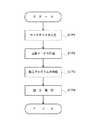
【図5】図5は、レーザ加工機を用いて加工を行う際の処理の流れを示すフローチャートである。
【図6】図6は、送り速度制御プログラムを示すフローチャートである。
【図7】図7は、本発明により切断加工する長方形断面の長尺材の断面図である。
【図8】図8は、コードパラメータ入力画面をイメージ化した図である。
【図9】図9は、本発明による長方形状断面の長尺材の加工制御例で、(a)は、加工制御を説明する長方形状断面の長尺材の模式斜視図、(b)は、(a)の加工制御を説明する図2のA方向矢視図、(c)は、(a)の加工を実行する加工プログラムの一部を示す図である。
【図10】図10は、本発明による三角形断面の長尺材の加工制御例で、(a)は、加工制御を説明する三角形断面の長尺材の模式斜視図、(b)は、(a)の加工制御を説明する図2のA方向矢視図である。
【符号の説明】
1……3次元線状加工装置(レーザ加工機)
10……回転保持駆動手段(チャック)
26……加工部(トーチ)
55……加工実行手段(加工制御部)
59……軸速度演算手段(加工データ演算部)
61……上限速度判定手段(速度クランプ判定部)
63……速度補正手段(速度補正部)
66……レーザ出力条件変更手段(レーザ発振制御部)
70……ワーク
A、B……第2及び第3の回転軸(A、B軸)
C……第1の回転軸(C軸)
Fr……送り速度
P1……始点(始点位置)
P2……中間点(中間通過位置)
P3……終点(終点位置)
PRO……加工プログラム
RZ……レーザ光
ωa、ωb、ωc……第1、第2及び第3の回転軸方向の角速度(A軸角速度、B軸角速度、C軸角速度、)
Fx、Fy、Fz……第1、第2及び第3の軸方向の移動速度(X軸移動速度、Y軸移動速度、Z軸移動速度)
X、Y、Z……第1及び互いに直交する第2及び第3の軸(X、Y、Z軸)ωamax、ωbmax、ωcmax、Fxmax、Fymax、Fzmax……所定の上限値(A軸最大角速度、B軸最大角速度、C軸最大角速度、X軸最大移動速度、Y軸最大移動速度、Z軸最大移動速度)
ωamdf、ωbmdf、ωcmdf、Fxmdf、Fymdf、Fzmdf……補正された速度(A軸補正角速度、B軸補正角速度、C軸補正角速度、X軸補正移動速度、Y軸補正移動速度、Z軸補正移動速度)[0001]
BACKGROUND OF THE INVENTION
The present invention relates to a three-dimensional linear processing apparatus such as a laser processing machine, a plasma cutting processing machine, and a gas cutting processing machine that can perform three-dimensional processing of a long material such as a pipe.
[Prior art]
Conventionally, as this type of three-dimensional linear processing apparatus, a three-dimensional laser processing machine has been proposed in which the direction of a torch for irradiating laser light can be adjusted three-dimensionally with respect to a workpiece. Such a three-dimensional laser processing machine can process a workpiece three-dimensionally by a linear / circular interpolation command for moving the torch in a linear / arc shape or a cylindrical interpolation command for rotating the workpiece. For example, when the shape is a different shape having a corner, the linear / circular interpolation command and the cylindrical interpolation command described above are not controlled at the same time, so that the feed speed of the torch to the workpiece is constant in the machining path passing through the corner. Inconveniences such as unevenness in the cut surface due to processing have occurred, and it has been difficult to maintain a non-uniform cut surface and continuously process the deformed material along the processing path. For this reason, the above-described processing of the deformed material has to process each processed surface of the workpiece, which takes time and labor, and it is difficult to realize high-speed processing.
[Problems to be solved by the invention]
Therefore, there is known a method of continuously machining a machining path passing through a corner in a workpiece made of a deformed material described above by using an interpolation command of a minute line segment by a machining program created by a CAD / CAM device. Yes.
[0002]
However, such processing takes a lot of time and requires skill because of complicated calculations. In addition, it is inconvenient because a CAD / CAM device is required separately and a huge memory capacity for the created machining program needs to be prepared. In addition, since the interpolation command for the minute line segment is used, the machining speed is reduced by that amount, and it has been difficult to realize high-speed machining.
[0003]
In view of the above-described circumstances, the present invention can realize high-speed processing by continuously processing a workpiece such as a deformed material while maintaining a good cut surface by processing. An object of the present invention is to provide a three-dimensional linear processing apparatus that is convenient without requiring a memory capacity for a CAM apparatus or a processing program, and that can easily perform processing without requiring skill. .
[Means for Solving the Problems]
That is, the first invention of the present invention isCross-sectional shape has corners Rotation holding drive means that can hold the work (70) around the first axis and can hold the workpiece (70) so as to be angularly rotatable in the direction of the first rotation axis (C) around the first axis. 10) is provided in the second and third axis (X, Y, Z) directions orthogonal to the first and mutually with respect to the work (70) held by the rotation holding drive means (10). Freely moveable and angularly rotated in the direction of the second and third rotation axes (A, B) around the second and third axesFree drive In the three-dimensional linear processing apparatus (1) having the processing part (26) provided in
When machining the corner of the workpiece, When executing the simultaneous 6-axis cylindrical interpolation command in which the start point (P1), the intermediate point (P2), the end point (P3), and the feed rate are specified in the machining program (PRO),The workpiece is rotated by a predetermined angle around the first axis, and the corner to be machined of the workpiece moves on a rotating arc having a predetermined rotation radius from the start point to the end point through the intermediate point, Rotation control means for driving and controlling the rotation holding drive means, and drive control so that the machining portion moves on the rotating arc having the predetermined radius of rotation in synchronization with the rotation of the corner to be machined. Processing unit control means, and The angular velocities (ωa) in the first, second and third rotation axis directions so that the feed rate of the machining unit (26) to the workpiece becomes the feed rate (Fr) specified in the machining program (PRO). , Ωb, ωc) and axial speed calculating means (57, 59) for calculating the moving speeds (Fx, Fy, Fz) in the first, second and third axial directions,
Angular velocities (ωa, ωb, ωc) in the first, second, and third rotational directions calculated by the axial speed calculating means (57, 59) and in the first, second, and third axial directions Based on the moving speed (Fx, Fy, Fz), the first, second and third axes (X, Y, Z) and the first, second and third rotation axes (A, B, C) ) Simultaneously controlling the workpieceThe corner of Is provided with processing execution means (55, 56) for executing processing on the above.
[0004]
A second aspect of the present invention is the angular velocity (ωa, ωb, ωc) in the first, second, and third rotation axis directions calculated by the shaft speed calculating means (57, 59), and Whether the moving speeds (Fx, Fy, Fz) in the first, second, and third axial directions exceed predetermined upper limit values (ωamax, ωbmax, ωcmax, Fzmax, Famax, Fbmax) set for each axis An upper limit speed determination means (61) is provided for determining whether or not
By the upper limit speed determining means (61), the angular velocities (ωa, ωb, ωc) in the first, second and third rotational axis directions and the moving speeds in the first, second and third axial directions ( Fx, Fy, Fz) is determined to exceed the upper limit value when it is determined that the predetermined upper limit value (ωamax, ωbmax, ωcmax, Fxmax, Fymax, Fzmax) set for each axis is exceeded. Speed correction means (63) for correcting the speed is provided,
The processing execution means (55, 56) is the work (70) at the speed (ωamdf, ωbmdf, ωcmdf, Fxmdf, Fymdf, Fzmddf) corrected by the speed correction means (63).The corner of Execute processing for.
[0005]
Moreover, 3rd invention among this invention is a said laser processing machine (1), The said three-dimensional linear processing apparatus,
When the speed (ωa, ωb, ωc, Fx, Fy, Fz) of each axis is corrected by the speed correction means (63), the laser beam is emitted from the processing section (26) of the laser processing machine (1). The laser output condition changing means (66) for changing the laser output condition of the laser beam (RZ) is provided.
[0006]
Note that the numbers in parentheses are for the sake of convenience indicating the corresponding elements in the drawings, and therefore the present description is not limited to the descriptions on the drawings.
[0007]
【The invention's effect】
As described above, according to the first aspect of the present invention, the machining execution means is the first, second and third angular velocities in the first, second and third rotational directions calculated by the axial speed calculation means. Since the first, second, and third axes and the first, second, and third rotation axes are simultaneously controlled based on the movement speed in the axial direction of 3 to perform machining on the workpiece, the cross-sectional shape is Even workpieces with different shapes with corners can be processed continuously along the machining path that passes through the corners, and there is no need to machine each workpiece surface as in the past. Speeding up can be realized. Further, since the simultaneous 6-axis cylindrical interpolation command is executed so that the feed rate of the machining part to the workpiece becomes the feed rate instructed in the machining program, the cutting surface is uneven while realizing high-speed machining. It can be processed into a good one without any. The simultaneous 6-axis cylindrical interpolation command is executed by instructing the start point, intermediate point, end point, and feed speed in the machining program. Therefore, a separate memory capacity for the CAD / CAM device and machining program is also required. In addition, it can be easily processed without skill.
[0008]
In the second invention of the present invention, the machining execution means executes machining on the workpiece at a speed corrected by the speed correction means based on the determination of the upper limit speed determination means. In addition to the effects of the first invention, Thus, even if the angular velocity in each rotational direction and the moving velocity in the axial direction exceed a predetermined upper limit value, continuous machining along the machining path passing through the corner can be accurately executed.
[0009]
According to a third aspect of the present invention, the laser output condition changing means changes the laser output condition when the speed of each axis is corrected by the speed correction means, in addition to the effects of the first invention. Thus, it is possible to set the laser output condition according to the corrected speed of each axis, and it is possible to reliably process the cut surface with a good quality without unevenness.
[0010]
DETAILED DESCRIPTION OF THE INVENTION
1 is an overall perspective view showing an example of a laser processing machine to which the present invention is applied, FIG. 2 is a side view showing the vicinity of a chuck in the laser processing machine of FIG. 1, and FIG. 3 is in the laser processing machine of FIG. FIG. 4 is a block diagram showing a control device in the laser processing machine of FIG. 1, FIG. 5 is a flowchart showing a flow of processing when processing is performed using the laser processing machine, FIG. 6 is a flowchart showing a feed rate control program, FIG. 7 is a cross-sectional view of a long material having a rectangular cross section to be cut according to the present invention, FIG. 8 is an image of a code parameter input screen, and FIG. It is an example of processing control of the long material of the rectangular cross section by this invention, (a) is a model perspective view of the long material of the rectangular cross section explaining processing control, (b) is processing control of (a). A direction arrow view of FIG. 2 to explain, (c FIG. 10 is a diagram showing a part of a machining program for executing the machining of (a), FIG. 10 is an example of machining control of a long material having a triangular cross section according to the present invention, and (a) is a triangular cross section for explaining machining control. FIG. 2B is a schematic perspective view of the long material, and FIG. 2B is a view in the direction of the arrow A in FIG. 2 for explaining the processing control of FIG.
[0011]
The laser processing machine 1 (three-dimensional linear processing machine) to which the present invention is applied is, for example, a pipe machining NCN apparatus (NC cutting machine) as shown in FIG. 1, and includes a
[0012]
The
[0013]
The
[0014]
Next, the laser irradiation apparatus 1b includes a
[0015]
Further, the
[0016]
The laser oscillator described above may be any one as long as it can stably irradiate a laser beam with a predetermined output capable of processing such as cutting and drilling of the
[0017]
The processing head
[0018]
As shown in FIG. 3, the
[0019]
Similarly, the
[0020]
Further, below the
[0021]
As shown in FIG. 3, the
[0022]
The
[0023]
Inside the
[0024]
A
[0025]
As shown in FIG. 4, the control device 1 c of the
[0026]
The
[0027]
An operator (operator) first positions the
[0028]
Next, the operator inputs a start command via a start switch (not shown) provided in the control device 1 c, and the
[0029]
Further, the operator inputs a command CM1 for creating the machining program PRO via the
[0030]
In step STP1, the program
[0031]
In step STP2, when the input of the work data WD is completed, the program
[0032]
When the input of the code parameter CP is completed, the program
[0033]
When the operator determines that the displayed three-dimensional data RD is not a desired machining shape, the program
[0034]
When the creation of the three-dimensional data RD is completed in step STP2, the process enters step STP3, and the program
[0035]
The machining program PRO is a linear interpolation command (X001, Yp1, Zp1, Ap1, Bp1, Cp1) of coordinate positions (hereinafter simply referred to as “control coordinate positions”) at the position P1 at the block N001 at the block N001. G01) is instructed to process, and the feed speed Fr at that time is 5,000 mm / min. In the next blocks N002 and N003, as shown in FIG. 9B, the rotation angle (C-axis rotation angle) of the
[0036]
Thereafter, in the machining program PRO, a linear interpolation command (G01) for machining the surface S23 and a simultaneous 6-axis cylindrical interpolation command (G12) similar to the above for machining the corner C3 are provided by the
[0037]
That is, in the simultaneous 6-axis cylindrical interpolation command of the machining program PRO, each control coordinate position Xp1, Yp2, Zp2, Ap1, Bp1, Cp2 of the intermediate passing position P2 when performing cylindrical interpolation at block N002, and block N003. The control coordinate positions Xp1, Yp3, Zp3, Ap1, Bp1, and Cp3 of the end point position P3 at which simultaneous 6-axis cylindrical interpolation is performed are indicated. As a result, in block N002, the C-axis coordinate position Cp1 for which the linear interpolation command is completed is rotated from the C-axis, and thus the
[0038]
In step STP3, when the machining program PRO including the simultaneous 6-axis cylindrical interpolation command as described above is generated by the program
[0039]
When the machining program PRO is generated, step STP4 in FIG. 5 is entered, and the operator operates the
[0040]
At this time, if the above-described simultaneous 6-axis cylindrical interpolation command (G12) is instructed in the machining program PRO, the
[0041]
For example, as shown in FIGS. 9A and 9B, the
[0042]
First, a linear interpolation command (G01) is executed between the corners C1 and C2. That is, the
[0043]
When the
[0044]
Thus, for example, when the
[0045]
After passing the intermediate passage position P2, the
[0046]
When the cutting of the corner C2 portion is completed, the command (G01) is executed again between the corners C2 and C3. That is, the laser beam RZ moves on the L23 at the feed speed Fr in the Y-axis K direction similarly to the straight line L12 described above, and cuts the
[0047]
When the laser beam RZ reaches the corner C3 (that is, when the cutting of the straight line L23 is completed), the corner C3 (corner arc CA3) is then cut while rotating the
[0048]
The simultaneous 6-axis cylindrical interpolation command described above is a simple processing example of a square pipe by drive control in the Y, Z, and C axis directions, but the drive control direction is limited to the Y, Z, and C axes. In addition, the X-axis direction drive control by the table 5 via the
[0049]
Note that the C-axis angular velocity ωc calculated in step STP4 is the C-axis angular velocity ωc that is required when the
[0050]
Therefore, when executing the simultaneous 6-axis cylindrical interpolation command, the
[0051]
That is, in the feed speed control program FCP, in step STP101, the machining data
[0052]
Next, in step STP102, the machining data
[0053]
Further, in step STP103, the machining
[0054]
That is, in step STP105, the machining data
[0055]
In step STP106, the
[0056]
When the above correction is completed, the
[0057]
When it is determined in step STP105 that the C-axis angular velocity ωc is smaller than the C-axis maximum angular velocity ωcmax (Yes in step STP105), the speed
[0058]
In step STP107, the machining data
[0059]
In step STP104, the
[0060]
Thus, when the above-described correction is completed, the
[0061]
On the other hand, when each shaft speed Fx, Fy, Fz, ωa, ωb is smaller than any of the shaft maximum speeds Fxmax, Fymax, Fzmax, ωamax, ωbmax (Yes in step STP107), the speed
[0062]
In step 108, the
[0063]
Thus, when executing the simultaneous 6-axis cylindrical interpolation command, the
[0064]
In the above-described embodiment, a case is described in which a corner of a
[0065]
As described above, in the
[0066]
In the
[0067]
In the present embodiment described above, a laser processing machine is shown as an example of a three-dimensional linear processing machine. However, any laser processing machine may be used as long as it can process a workpiece in three dimensions, for example, three-dimensional plasma cutting. The present invention can also be applied to a processing machine such as a processing machine or a three-dimensional gas cutting processing machine.
[Brief description of the drawings]
FIG. 1 is an overall perspective view showing an example of a laser processing machine to which the present invention is applied.
FIG. 2 is a side view showing the vicinity of the chuck in the laser beam machine shown in FIG. 1;
FIG. 3 is an enlarged cross-sectional view of a processing head main body portion in the laser processing machine of FIG. 1;
4 is a block diagram showing a control device in the laser beam machine in FIG. 1. FIG.
FIG. 5 is a flowchart showing a flow of processing when processing is performed using a laser processing machine.
FIG. 6 is a flowchart showing a feed speed control program.
FIG. 7 is a cross-sectional view of an elongated material having a rectangular cross section to be cut according to the present invention.
FIG. 8 is an image of a code parameter input screen.
FIG. 9 is an example of processing control of a long material having a rectangular cross section according to the present invention. FIG. 9A is a schematic perspective view of a long material having a rectangular cross section for explaining the processing control, and FIG. FIG. 2A is a diagram showing a part of a machining program for executing the machining in FIG. 2A. FIG.
FIG. 10 is an example of processing control of a long material having a triangular cross section according to the present invention. FIG. 10A is a schematic perspective view of a long material having a triangular cross section for explaining the processing control, and FIG. It is an A direction arrow directional view of
[Explanation of symbols]
1 ... 3D linear processing equipment (laser processing machine)
10: Rotation holding drive means (chuck)
26 …… Processing part (torch)
55 …… Processing execution means (processing control unit)
59 …… Axis speed calculation means (machining data calculation section)
61 …… Upper limit speed judgment means (speed clamp judgment part)
63 …… Speed correction means (speed correction part)
66 …… Laser output condition changing means (laser oscillation control unit)
70 …… Work
A, B ... 2nd and 3rd axis of rotation (A, B axis)
C: 1st rotation axis (C axis)
Fr: Feeding speed
P1 …… Start point (start point position)
P2 …… Intermediate point (intermediate passage position)
P3 …… End point (end point position)
PRO …… Processing program
RZ ... Laser light
ωa, ωb, ωc: Angular velocities in the first, second and third rotation axis directions (A-axis angular velocity, B-axis angular velocity, C-axis angular velocity)
Fx, Fy, Fz: Movement speed in the first, second and third axial directions (X-axis movement speed, Y-axis movement speed, Z-axis movement speed)
X, Y, Z: first and second and third axes (X, Y, Z axes) orthogonal to each other, ωamax, ωbmax, ωcmax, Fxmax, Fymax, Fzmax ... predetermined upper limit value (A-axis maximum angular velocity , B-axis maximum angular velocity, C-axis maximum angular velocity, X-axis maximum travel speed, Y-axis maximum travel speed, Z-axis maximum travel speed)
ωamdf, ωbmdf, ωcmdf, Fxmdf, Fymdf, Fzmddf... corrected speed (A-axis corrected angular speed, B-axis corrected angular speed, C-axis corrected angular speed, X-axis corrected moving speed, Y-axis corrected moving speed, Z-axis corrected moving speed )
Claims (3)
Translated fromJapanese前記ワークの前記コーナーを加工する際の、始点、中間点及び終点及び送り速度が加工プログラム中で指示された同時6軸円筒補間指令を実行する際に、前記ワークを前記第1の軸を中心に所定角度回転させ、前記ワークの加工すべきコーナーが、前記始点から中間点を経て終点まで、所定の回転半径を有する回転円弧上を移動するように、前記回転保持駆動手段を駆動制御する回転制御手段、前記加工部を、前記所定の回転半径を有する前記回転円弧上を、前記加工すべきコーナーの回転と同期する形で移動するように、駆動制御する、加工部制御手段、及び、前記加工部のワークに対する送り速度が前記加工プログラム中で指示された送り速度となるように、前記第1、第2及び第3の回転軸方向の角速度及び、前記第1、第2及び第3の軸方向の移動速度を演算する軸速度演算手段を設け、
該軸速度演算手段により演算された前記第1、第2及び第3の回転方向の角速度及び、前記第1、第2及び第3の軸方向の移動速度に基づいて、前記第1、第2及び第3の軸及び前記第1、第2及び第3の回転軸を同時に制御して、ワークの前記コーナーに対する加工を実行する加工実行手段を設けて構成した、3次元線状加工装置。Rotation holding driving means capable of holdinga workpiecehaving a cross-sectional shape around a first axis, and capable of holding the workpiece so as to be angularly rotatable in the direction of the first rotation axis around the first axis. It is provided and can be driven to move in the second and third axial directions orthogonal to each other with respect to the workpiece held by the rotation holding driving means, and the second and third axes are the center. In a three-dimensional linear processing apparatus having a processing portion provided so as to becapable of angular rotationdrive in the second and third rotation axis directions
When executing the simultaneous 6-axis cylindrical interpolation command in whichthe start point, the intermediate point, the end point, and the feed rate are specified in the machining programwhen machining the corner of the workpiece , theworkpiece is centered on the first axis. Rotation for driving and controlling the rotation holding driving means so that a corner to be machined of the workpiece moves on a rotating arc having a predetermined rotation radius from the start point to the end point through the intermediate point. A control unit, a processing unit control unit for driving and controlling the processing unit so as to move on the rotating arc having the predetermined radius of rotation in synchronization with the rotation of the corner to be processed; and The first, second, and third angular velocities in the first, second, and third rotational axis directions, and the first, second, and third so that the feed rate of the machining unit to the workpiece becomes the feed rate that is instructed in the machining program. The shaft speed calculating means for calculating a moving speed of the axial provided,
Based on the angular velocities in the first, second and third rotational directions calculated by the axial speed calculating means and the moving speeds in the first, second and third axial directions, the first and second A three-dimensional linear machining apparatus comprising a machining execution means that simultaneously controls the third axis and the first, second, and third rotation axes to perform machining on thecorner of the workpiece.
前記上限速度判定手段により、前記第1、第2及び第3の回転軸方向の角速度及び、前記第1、第2及び第3の軸方向の移動速度が、各軸について設定された所定の上限値を超えるものと判定された場合に、前記上限値を超えると判定された速度を、補正する速度補正手段を設け、
前記加工実行手段は、前記速度補正手段により補正された速度で前記ワークの前記コーナーに対する加工を実行することを特徴とする、請求項1記載の3次元線状加工装置。The calculated angular velocities in the first, second, and third rotational axis directions and the moving speeds in the first, second, and third axial directions are set for each axis by the axial velocity calculating means. An upper limit speed determining means for determining whether or not a predetermined upper limit value is exceeded,
The upper limit speed determining means sets the angular speeds in the first, second and third rotation axis directions and the movement speeds in the first, second and third axis directions to predetermined upper limits set for each axis. When it is determined to exceed the value, a speed correction means for correcting the speed determined to exceed the upper limit value is provided,
2. The three-dimensional linear machining apparatus according to claim 1, wherein the machining execution unit performs machining on thecorner of the workpiece at a speed corrected by the speed correction unit.
前記速度補正手段により前記各軸の速度が補正された場合に、前記レーザ加工機の前記加工部から射出されるレーザ光のレーザ出力条件を変更するレーザ出力条件変更手段を設けて構成した、請求項2記載の3次元線状加工装置。The three-dimensional linear processing apparatus is a laser processing machine,
A laser output condition changing unit is provided to change a laser output condition of a laser beam emitted from the processing unit of the laser processing machine when the speed of each axis is corrected by the speed correction unit. Item 3. A three-dimensional linear processing apparatus according to item 2.
Priority Applications (4)
| Application Number | Priority Date | Filing Date | Title |
|---|---|---|---|
| JP2002113918AJP3607259B2 (en) | 2002-04-16 | 2002-04-16 | 3D linear processing equipment |
| EP03008257AEP1362667A1 (en) | 2002-04-16 | 2003-04-09 | Three-dimensional linear machining apparatus |
| CNB031218172ACN1259602C (en) | 2002-04-16 | 2003-04-10 | Three-D linear processing device |
| US10/412,907US6930275B2 (en) | 2002-04-16 | 2003-04-14 | Three dimensional linear machining apparatus |
Applications Claiming Priority (1)
| Application Number | Priority Date | Filing Date | Title |
|---|---|---|---|
| JP2002113918AJP3607259B2 (en) | 2002-04-16 | 2002-04-16 | 3D linear processing equipment |
Publications (2)
| Publication Number | Publication Date |
|---|---|
| JP2003308104A JP2003308104A (en) | 2003-10-31 |
| JP3607259B2true JP3607259B2 (en) | 2005-01-05 |
Family
ID=28786718
Family Applications (1)
| Application Number | Title | Priority Date | Filing Date |
|---|---|---|---|
| JP2002113918AExpired - LifetimeJP3607259B2 (en) | 2002-04-16 | 2002-04-16 | 3D linear processing equipment |
Country Status (4)
| Country | Link |
|---|---|
| US (1) | US6930275B2 (en) |
| EP (1) | EP1362667A1 (en) |
| JP (1) | JP3607259B2 (en) |
| CN (1) | CN1259602C (en) |
Families Citing this family (99)
| Publication number | Priority date | Publication date | Assignee | Title |
|---|---|---|---|---|
| US11026768B2 (en) | 1998-10-08 | 2021-06-08 | Align Technology, Inc. | Dental appliance reinforcement |
| US8204618B2 (en)* | 2008-03-24 | 2012-06-19 | Hypertherm, Inc. | Method and apparatus for operating an automated high temperature thermal cutting system |
| JP2005028423A (en)* | 2003-07-09 | 2005-02-03 | Disco Abrasive Syst Ltd | Laser processing method and laser processing apparatus |
| US9492245B2 (en) | 2004-02-27 | 2016-11-15 | Align Technology, Inc. | Method and system for providing dynamic orthodontic assessment and treatment profiles |
| DE102004011769B3 (en)* | 2004-03-09 | 2005-08-18 | Kuka Schweissanlagen Gmbh | Laser processing, especially welding vehicle bodies, body parts, involves deflecting laser beam essentially by moving manipulator hand axles by variable deflection angles, controlling variable power laser source depending on beam movements |
| JP2005334923A (en)* | 2004-05-26 | 2005-12-08 | Yamazaki Mazak Corp | Piercing method in laser beam machine |
| JP2006159254A (en)* | 2004-12-07 | 2006-06-22 | Disco Abrasive Syst Ltd | Laser processing equipment |
| US20060213884A1 (en)* | 2005-03-23 | 2006-09-28 | Button International Co., Ltd. | Multi-angular laser processing apparatus |
| JP2006341283A (en)* | 2005-06-09 | 2006-12-21 | Fanuc Ltd | Positioner for arc welding, and arc welding robot system |
| US7878805B2 (en) | 2007-05-25 | 2011-02-01 | Align Technology, Inc. | Tabbed dental appliance |
| US7767932B2 (en)* | 2007-06-29 | 2010-08-03 | Trumpf, Inc. | High dynamics laser processing machine |
| DE502007002940D1 (en)* | 2007-07-17 | 2010-04-08 | Trumpf Werkzeugmaschinen Gmbh | Mechanical arrangement for processing rod-like workpieces with a device for workpiece support |
| DE102007048121B4 (en)* | 2007-10-05 | 2013-09-19 | Alfing Kessler Sondermaschinen Gmbh | Clamping device for a machine tool with a flatness measurement |
| US8738394B2 (en) | 2007-11-08 | 2014-05-27 | Eric E. Kuo | Clinical data file |
| US8108189B2 (en) | 2008-03-25 | 2012-01-31 | Align Technologies, Inc. | Reconstruction of non-visible part of tooth |
| US8092215B2 (en) | 2008-05-23 | 2012-01-10 | Align Technology, Inc. | Smile designer |
| US9492243B2 (en) | 2008-05-23 | 2016-11-15 | Align Technology, Inc. | Dental implant positioning |
| US8172569B2 (en) | 2008-06-12 | 2012-05-08 | Align Technology, Inc. | Dental appliance |
| GB0814828D0 (en)* | 2008-08-14 | 2008-09-17 | In Situ Oilfield Services Ltd | Chuck device and method |
| US8152518B2 (en) | 2008-10-08 | 2012-04-10 | Align Technology, Inc. | Dental positioning appliance having metallic portion |
| EP2177299B1 (en)* | 2008-10-17 | 2013-07-31 | PRIMA INDUSTRIE S.p.A. | laser machine |
| US8292617B2 (en) | 2009-03-19 | 2012-10-23 | Align Technology, Inc. | Dental wire attachment |
| US20110015772A1 (en)* | 2009-07-14 | 2011-01-20 | Salazar Mario A | Measurement System |
| US8765031B2 (en) | 2009-08-13 | 2014-07-01 | Align Technology, Inc. | Method of forming a dental appliance |
| DE102009044316B4 (en)* | 2009-10-22 | 2015-04-30 | Ewag Ag | Method for producing a surface and / or edge on a blank and laser processing device for carrying out the method |
| WO2011104734A1 (en)* | 2010-02-26 | 2011-09-01 | Tube Tech Machinery S.R.L. | Method of and machine for cutting or welding pipes with contactless measuring of the distance between the latter and the surface of the pipe |
| US9241774B2 (en) | 2010-04-30 | 2016-01-26 | Align Technology, Inc. | Patterned dental positioning appliance |
| US9211166B2 (en) | 2010-04-30 | 2015-12-15 | Align Technology, Inc. | Individualized orthodontic treatment index |
| JP4847613B2 (en)* | 2010-05-10 | 2011-12-28 | ファナック株式会社 | Numerical controller for multi-axis machines |
| JP4813616B1 (en)* | 2010-07-12 | 2011-11-09 | ファナック株式会社 | Numerical control device for machine tool having speed control function during arc motion |
| CN102126082B (en)* | 2010-12-24 | 2013-08-21 | 陈乃奇 | Laser exposure cutter and laser-based three-dimensional direct exposure imaging method |
| ITMO20110045A1 (en)* | 2011-02-28 | 2012-08-29 | Fabbi S R L | AUTOMATIC CUTTER, PARTICULARLY FOR PALLET AND SIMILAR PLASTIC PROTECTIVE PACKAGING. |
| ITPN20110017A1 (en)* | 2011-03-21 | 2012-09-22 | Paracao E Servicos Lda | MACHINE FOR LASER PROCESSING OF FLAT ELEMENTS |
| US9314873B2 (en) | 2011-03-21 | 2016-04-19 | Electronics And Computer Highlights | Apparatus for laser working of flat elements |
| US9403238B2 (en)* | 2011-09-21 | 2016-08-02 | Align Technology, Inc. | Laser cutting |
| AU2015202747B2 (en)* | 2011-09-21 | 2016-06-23 | Align Technology, Inc. | Laser cutting system and method of laser cutting |
| DE102011116974A1 (en)* | 2011-10-26 | 2013-05-02 | Vollmer Werke Maschinenfabrik Gmbh | Device and method for producing a Führungsfase on a workpiece, in particular on a cutting tool |
| US9375300B2 (en) | 2012-02-02 | 2016-06-28 | Align Technology, Inc. | Identifying forces on a tooth |
| US9220580B2 (en) | 2012-03-01 | 2015-12-29 | Align Technology, Inc. | Determining a dental treatment difficulty |
| US9414897B2 (en) | 2012-05-22 | 2016-08-16 | Align Technology, Inc. | Adjustment of tooth position in a virtual dental model |
| CN105103066B (en) | 2013-04-12 | 2017-12-15 | 三菱电机株式会社 | Numerical control program editing device, numerical control program edit methods and program |
| JP6025652B2 (en)* | 2013-05-15 | 2016-11-16 | 株式会社アマダホールディングス | Laser processing method and laser processing program creation device |
| EP2865479A1 (en)* | 2013-10-22 | 2015-04-29 | Siemens Aktiengesellschaft | Method and system for generating a component using thermal spraying and laser fusing |
| CN103934528B (en)* | 2014-04-14 | 2016-02-10 | 上海交通大学 | A kind of six-axis linkage interpolating method for spark machined |
| WO2016038687A1 (en)* | 2014-09-09 | 2016-03-17 | 三菱電機株式会社 | Numerical control apparatus |
| US9610141B2 (en) | 2014-09-19 | 2017-04-04 | Align Technology, Inc. | Arch expanding appliance |
| US10449016B2 (en) | 2014-09-19 | 2019-10-22 | Align Technology, Inc. | Arch adjustment appliance |
| JP5992026B2 (en)* | 2014-10-24 | 2016-09-14 | 株式会社アマダホールディングス | LASER CUTTING METHOD, CONTROL DEVICE AND PROGRAMMING DEVICE IN LASER CUTTING MACHINE |
| US9744001B2 (en) | 2014-11-13 | 2017-08-29 | Align Technology, Inc. | Dental appliance with cavity for an unerupted or erupting tooth |
| US10504386B2 (en) | 2015-01-27 | 2019-12-10 | Align Technology, Inc. | Training method and system for oral-cavity-imaging-and-modeling equipment |
| JP6847865B2 (en) | 2015-06-22 | 2021-03-24 | エレクトロ サイエンティフィック インダストリーズ インコーポレーテッド | Multi-axis machine tool and how to control it |
| US11554000B2 (en) | 2015-11-12 | 2023-01-17 | Align Technology, Inc. | Dental attachment formation structure |
| US11931222B2 (en) | 2015-11-12 | 2024-03-19 | Align Technology, Inc. | Dental attachment formation structures |
| US11103330B2 (en) | 2015-12-09 | 2021-08-31 | Align Technology, Inc. | Dental attachment placement structure |
| US11596502B2 (en) | 2015-12-09 | 2023-03-07 | Align Technology, Inc. | Dental attachment placement structure |
| WO2017218947A1 (en) | 2016-06-17 | 2017-12-21 | Align Technology, Inc. | Intraoral appliances with sensing |
| US10383705B2 (en) | 2016-06-17 | 2019-08-20 | Align Technology, Inc. | Orthodontic appliance performance monitor |
| CA3030676A1 (en) | 2016-07-27 | 2018-02-01 | Align Technology, Inc. | Intraoral scanner with dental diagnostics capabilities |
| WO2018047823A1 (en)* | 2016-09-09 | 2018-03-15 | 三菱電機株式会社 | Laser machining device |
| CN117257492A (en) | 2016-11-04 | 2023-12-22 | 阿莱恩技术有限公司 | Method and apparatus for dental imaging |
| EP3547952B1 (en) | 2016-12-02 | 2020-11-04 | Align Technology, Inc. | Palatal expander |
| WO2018102770A1 (en) | 2016-12-02 | 2018-06-07 | Align Technology, Inc. | Force control, stop mechanism, regulating structure of removable arch adjustment appliance |
| AU2017366755B2 (en) | 2016-12-02 | 2022-07-28 | Align Technology, Inc. | Methods and apparatuses for customizing rapid palatal expanders using digital models |
| US11026831B2 (en) | 2016-12-02 | 2021-06-08 | Align Technology, Inc. | Dental appliance features for speech enhancement |
| US10548700B2 (en) | 2016-12-16 | 2020-02-04 | Align Technology, Inc. | Dental appliance etch template |
| US10779718B2 (en) | 2017-02-13 | 2020-09-22 | Align Technology, Inc. | Cheek retractor and mobile device holder |
| WO2018183358A1 (en) | 2017-03-27 | 2018-10-04 | Align Technology, Inc. | Apparatuses and methods assisting in dental therapies |
| US10613515B2 (en) | 2017-03-31 | 2020-04-07 | Align Technology, Inc. | Orthodontic appliances including at least partially un-erupted teeth and method of forming them |
| US11045283B2 (en) | 2017-06-09 | 2021-06-29 | Align Technology, Inc. | Palatal expander with skeletal anchorage devices |
| CN116942335A (en) | 2017-06-16 | 2023-10-27 | 阿莱恩技术有限公司 | Automatic detection of tooth type and eruption status |
| US10639134B2 (en) | 2017-06-26 | 2020-05-05 | Align Technology, Inc. | Biosensor performance indicator for intraoral appliances |
| US10885521B2 (en) | 2017-07-17 | 2021-01-05 | Align Technology, Inc. | Method and apparatuses for interactive ordering of dental aligners |
| CN111107806B (en) | 2017-07-21 | 2022-04-19 | 阿莱恩技术有限公司 | Jaw profile anchoring |
| EP4278957A3 (en) | 2017-07-27 | 2024-01-24 | Align Technology, Inc. | System and methods for processing an orthodontic aligner by means of an optical coherence tomography |
| CN110996842B (en) | 2017-07-27 | 2022-10-14 | 阿莱恩技术有限公司 | Tooth Staining, Transparency and Glazing |
| CN107262872B (en)* | 2017-08-08 | 2024-04-12 | 安庆帆盛机电科技有限公司 | Method for cutting holes on cylinder at one time |
| US12274597B2 (en) | 2017-08-11 | 2025-04-15 | Align Technology, Inc. | Dental attachment template tray systems |
| US11116605B2 (en) | 2017-08-15 | 2021-09-14 | Align Technology, Inc. | Buccal corridor assessment and computation |
| US11123156B2 (en) | 2017-08-17 | 2021-09-21 | Align Technology, Inc. | Dental appliance compliance monitoring |
| US12171575B2 (en) | 2017-10-04 | 2024-12-24 | Align Technology, Inc. | Intraoral systems and methods for sampling soft-tissue |
| US10813720B2 (en) | 2017-10-05 | 2020-10-27 | Align Technology, Inc. | Interproximal reduction templates |
| CN111565668B (en) | 2017-10-27 | 2022-06-07 | 阿莱恩技术有限公司 | Substitute occlusion adjusting structure |
| CN111295153B (en) | 2017-10-31 | 2023-06-16 | 阿莱恩技术有限公司 | Dental appliance with selective bite loading and controlled tip staggering |
| CN119235481A (en) | 2017-11-01 | 2025-01-03 | 阿莱恩技术有限公司 | Automatic treatment planning |
| US11534974B2 (en) | 2017-11-17 | 2022-12-27 | Align Technology, Inc. | Customized fabrication of orthodontic retainers based on patient anatomy |
| SI3488960T1 (en)* | 2017-11-23 | 2021-05-31 | Dallan S.P.A. | Apparatus for laser or plasma cutting of pieces of laminar material wound in coil |
| US11219506B2 (en) | 2017-11-30 | 2022-01-11 | Align Technology, Inc. | Sensors for monitoring oral appliances |
| US11432908B2 (en) | 2017-12-15 | 2022-09-06 | Align Technology, Inc. | Closed loop adaptive orthodontic treatment methods and apparatuses |
| US10980613B2 (en) | 2017-12-29 | 2021-04-20 | Align Technology, Inc. | Augmented reality enhancements for dental practitioners |
| US10813727B2 (en) | 2018-01-26 | 2020-10-27 | Align Technology, Inc. | Diagnostic intraoral tracking |
| US11937991B2 (en) | 2018-03-27 | 2024-03-26 | Align Technology, Inc. | Dental attachment placement structure |
| EP3773320B1 (en) | 2018-04-11 | 2024-05-15 | Align Technology, Inc. | Releasable palatal expanders |
| CN108733000B (en)* | 2018-06-21 | 2020-10-27 | 上海柏楚电子科技股份有限公司 | Large-breadth galvanometer processing system and control method |
| TWI704978B (en)* | 2018-09-26 | 2020-09-21 | 禾璟科技有限公司 | Computer programming products that can be applied to the grinder |
| US11389907B2 (en)* | 2018-12-03 | 2022-07-19 | Mitsubishi Electric Corporation | Laser machining apparatus and laser machining method |
| CN110286613B (en)* | 2019-05-13 | 2022-02-01 | 大族激光科技产业集团股份有限公司 | Double-shaft laser control system |
| JP7324696B2 (en)* | 2019-11-29 | 2023-08-10 | 株式会社アマダ | Laser processing method, processing program creation support program, and processing program creation support device |
| US20230297078A1 (en)* | 2020-08-25 | 2023-09-21 | Fanuc Corporation | Speed adjustment device |
| JP2024097181A (en)* | 2023-01-05 | 2024-07-18 | 株式会社 アルファー精工 | Encoder scale, its manufacturing method, manufacturing device, and control device using the encoder scale |
Family Cites Families (15)
| Publication number | Priority date | Publication date | Assignee | Title |
|---|---|---|---|---|
| IT1148370B (en)* | 1981-07-17 | 1986-12-03 | Fuji Tool & Die | THREE-DIMENSIONAL LASER CUTTING SYSTEM WITH THE REPRODUCTION METHOD |
| FR2556627B1 (en)* | 1983-12-16 | 1990-10-12 | Honda Motor Co Ltd | DRILL |
| DE3614082A1 (en)* | 1986-04-25 | 1987-10-29 | Elcede Gmbh | DEVICE AND METHOD FOR MAKING CUTS IN THE EXTERNAL SURFACES OF AT LEAST ONE BODY |
| US4908493A (en)* | 1988-05-31 | 1990-03-13 | Midwest Research Institute | Method and apparatus for optimizing the efficiency and quality of laser material processing |
| IL89484A (en)* | 1989-03-03 | 1992-08-18 | Nct Ltd Numerical Control Tech | System for automatic finishing of machined parts |
| US5225650A (en)* | 1989-07-14 | 1993-07-06 | Maho Aktiengesellschaft | Process and device for the manufacture of cavities in workpieces through laser beams |
| EP0407969B1 (en)* | 1989-07-14 | 1993-10-06 | MAHO Aktiengesellschaft | Process and device for manufacturing hollow spaces in workpieces using a laser beam |
| US5239159A (en)* | 1990-05-31 | 1993-08-24 | Fanuc Ltd. | Nozzle movement system for laser machining equipment |
| JPH04100689A (en)* | 1990-08-14 | 1992-04-02 | Tsubakimoto Chain Co | 5-axis table for laser processing machine |
| FR2681546B1 (en)* | 1991-09-20 | 1995-12-08 | Essilor Int | MULTI-AXIS DIGITAL CONTROL MACHINING METHOD AND MACHINE. |
| JPH05104366A (en)* | 1991-10-17 | 1993-04-27 | Fanuc Ltd | Combined machine tool |
| US5340962A (en)* | 1992-08-14 | 1994-08-23 | Lumonics Corporation | Automatic control of laser beam tool positioning |
| WO1995008416A1 (en)* | 1993-09-20 | 1995-03-30 | Massachusetts Institute Of Technology | Process for rapidly forming laminated dies and said dies |
| JP3071758B2 (en)* | 1998-05-20 | 2000-07-31 | ヤマザキマザック株式会社 | Three-dimensional laser beam machine and processing control method for processing program in three-dimensional laser beam machine |
| JP2001001174A (en) | 1999-06-23 | 2001-01-09 | Amada Wasino Co Ltd | Method for cutting pipe in laser beam machine and device therefor |
- 2002
- 2002-04-16JPJP2002113918Apatent/JP3607259B2/ennot_activeExpired - Lifetime
- 2003
- 2003-04-09EPEP03008257Apatent/EP1362667A1/ennot_activeWithdrawn
- 2003-04-10CNCNB031218172Apatent/CN1259602C/ennot_activeExpired - Fee Related
- 2003-04-14USUS10/412,907patent/US6930275B2/ennot_activeExpired - Lifetime
Also Published As
| Publication number | Publication date |
|---|---|
| CN1452036A (en) | 2003-10-29 |
| EP1362667A1 (en) | 2003-11-19 |
| JP2003308104A (en) | 2003-10-31 |
| US6930275B2 (en) | 2005-08-16 |
| US20030192867A1 (en) | 2003-10-16 |
| CN1259602C (en) | 2006-06-14 |
Similar Documents
| Publication | Publication Date | Title |
|---|---|---|
| JP3607259B2 (en) | 3D linear processing equipment | |
| JP5122833B2 (en) | Laser processing method and laser processing apparatus | |
| EP1943048B1 (en) | Laser processing robot control system, control method and control program medium | |
| JPH11320145A (en) | Three-dimensional laser processing machine, and control method for compiling processing program in three-dimensional laser processing machine | |
| JP3476288B2 (en) | Solid processing equipment using YAG cutting tool | |
| JP3746019B2 (en) | Laser processing machine | |
| JP7195110B2 (en) | Machine tools and controllers | |
| JP2004174709A (en) | Method and device for machining workpiece | |
| GB2447455A (en) | A support arrangement for a treatment device | |
| JP3599800B2 (en) | Spindle normal direction control method for numerically controlled machine tools | |
| WO2016038687A1 (en) | Numerical control apparatus | |
| EP2560786B1 (en) | Method and device for cutting openings in flat, concave or convex surfaces | |
| WO2003031110A1 (en) | Three-dimensional laser beam machine | |
| Hatwig et al. | An automated path planning system for a robot with a laser scanner for remote laser cutting and welding | |
| JP2005271148A (en) | Tool path data generation device and control device including the same | |
| JP6980504B2 (en) | Cutting method, cutting program, automatic generation program, control system, cutting device and manufacturing method of work material | |
| JP3424130B2 (en) | Laser processing machine | |
| JPH09327784A (en) | Interpolation device and interpolation method for numerical control device for laser processing machine | |
| JP2000339011A (en) | Three-dimensional linear finishing machine and production control method for machining program of the finishing machine | |
| JP2004174586A (en) | Numerical control device | |
| JP2019166578A (en) | Setting device for robot operation program, robot and robot control method | |
| KR20140040689A (en) | A method for working structural members | |
| JP4202305B2 (en) | 3D laser processing machine | |
| JP2872377B2 (en) | Laser processing machine with 3D automatic controller | |
| JP3578274B2 (en) | Numerically controlled machine tool |
Legal Events
| Date | Code | Title | Description |
|---|---|---|---|
| A977 | Report on retrieval | Free format text:JAPANESE INTERMEDIATE CODE: A971007 Effective date:20040621 | |
| A131 | Notification of reasons for refusal | Free format text:JAPANESE INTERMEDIATE CODE: A131 Effective date:20040629 | |
| A521 | Request for written amendment filed | Free format text:JAPANESE INTERMEDIATE CODE: A523 Effective date:20040825 | |
| TRDD | Decision of grant or rejection written | ||
| A01 | Written decision to grant a patent or to grant a registration (utility model) | Free format text:JAPANESE INTERMEDIATE CODE: A01 Effective date:20040928 | |
| A61 | First payment of annual fees (during grant procedure) | Free format text:JAPANESE INTERMEDIATE CODE: A61 Effective date:20041006 | |
| R150 | Certificate of patent or registration of utility model | Ref document number:3607259 Country of ref document:JP Free format text:JAPANESE INTERMEDIATE CODE: R150 Free format text:JAPANESE INTERMEDIATE CODE: R150 | |
| FPAY | Renewal fee payment (event date is renewal date of database) | Free format text:PAYMENT UNTIL: 20071015 Year of fee payment:3 | |
| FPAY | Renewal fee payment (event date is renewal date of database) | Free format text:PAYMENT UNTIL: 20081015 Year of fee payment:4 | |
| R250 | Receipt of annual fees | Free format text:JAPANESE INTERMEDIATE CODE: R250 | |
| FPAY | Renewal fee payment (event date is renewal date of database) | Free format text:PAYMENT UNTIL: 20091015 Year of fee payment:5 | |
| R250 | Receipt of annual fees | Free format text:JAPANESE INTERMEDIATE CODE: R250 | |
| FPAY | Renewal fee payment (event date is renewal date of database) | Free format text:PAYMENT UNTIL: 20101015 Year of fee payment:6 | |
| R250 | Receipt of annual fees | Free format text:JAPANESE INTERMEDIATE CODE: R250 | |
| FPAY | Renewal fee payment (event date is renewal date of database) | Free format text:PAYMENT UNTIL: 20111015 Year of fee payment:7 | |
| R250 | Receipt of annual fees | Free format text:JAPANESE INTERMEDIATE CODE: R250 | |
| FPAY | Renewal fee payment (event date is renewal date of database) | Free format text:PAYMENT UNTIL: 20111015 Year of fee payment:7 | |
| FPAY | Renewal fee payment (event date is renewal date of database) | Free format text:PAYMENT UNTIL: 20121015 Year of fee payment:8 | |
| R250 | Receipt of annual fees | Free format text:JAPANESE INTERMEDIATE CODE: R250 | |
| FPAY | Renewal fee payment (event date is renewal date of database) | Free format text:PAYMENT UNTIL: 20121015 Year of fee payment:8 | |
| FPAY | Renewal fee payment (event date is renewal date of database) | Free format text:PAYMENT UNTIL: 20131015 Year of fee payment:9 | |
| R250 | Receipt of annual fees | Free format text:JAPANESE INTERMEDIATE CODE: R250 | |
| R250 | Receipt of annual fees | Free format text:JAPANESE INTERMEDIATE CODE: R250 | |
| R250 | Receipt of annual fees | Free format text:JAPANESE INTERMEDIATE CODE: R250 | |
| R250 | Receipt of annual fees | Free format text:JAPANESE INTERMEDIATE CODE: R250 | |
| R250 | Receipt of annual fees | Free format text:JAPANESE INTERMEDIATE CODE: R250 | |
| R250 | Receipt of annual fees | Free format text:JAPANESE INTERMEDIATE CODE: R250 | |
| R250 | Receipt of annual fees | Free format text:JAPANESE INTERMEDIATE CODE: R250 | |
| R250 | Receipt of annual fees | Free format text:JAPANESE INTERMEDIATE CODE: R250 | |
| R250 | Receipt of annual fees | Free format text:JAPANESE INTERMEDIATE CODE: R250 | |
| R250 | Receipt of annual fees | Free format text:JAPANESE INTERMEDIATE CODE: R250 | |
| EXPY | Cancellation because of completion of term |