JP3607231B2 - High frequency heating balloon catheter - Google Patents
High frequency heating balloon catheterDownload PDFInfo
- Publication number
- JP3607231B2 JP3607231B2JP2001303112AJP2001303112AJP3607231B2JP 3607231 B2JP3607231 B2JP 3607231B2JP 2001303112 AJP2001303112 AJP 2001303112AJP 2001303112 AJP2001303112 AJP 2001303112AJP 3607231 B2JP3607231 B2JP 3607231B2
- Authority
- JP
- Japan
- Prior art keywords
- balloon
- frequency
- temperature
- shaft
- liquid
- Prior art date
- Legal status (The legal status is an assumption and is not a legal conclusion. Google has not performed a legal analysis and makes no representation as to the accuracy of the status listed.)
- Expired - Lifetime
Links
Images


Classifications
- A—HUMAN NECESSITIES
- A61—MEDICAL OR VETERINARY SCIENCE; HYGIENE
- A61B—DIAGNOSIS; SURGERY; IDENTIFICATION
- A61B18/00—Surgical instruments, devices or methods for transferring non-mechanical forms of energy to or from the body
- A61B18/04—Surgical instruments, devices or methods for transferring non-mechanical forms of energy to or from the body by heating
- A61B18/12—Surgical instruments, devices or methods for transferring non-mechanical forms of energy to or from the body by heating by passing a current through the tissue to be heated, e.g. high-frequency current
- A61B18/14—Probes or electrodes therefor
- A61B18/1492—Probes or electrodes therefor having a flexible, catheter-like structure, e.g. for heart ablation
- A—HUMAN NECESSITIES
- A61—MEDICAL OR VETERINARY SCIENCE; HYGIENE
- A61B—DIAGNOSIS; SURGERY; IDENTIFICATION
- A61B17/00—Surgical instruments, devices or methods
- A61B2017/00017—Electrical control of surgical instruments
- A61B2017/00022—Sensing or detecting at the treatment site
- A61B2017/00084—Temperature
- A—HUMAN NECESSITIES
- A61—MEDICAL OR VETERINARY SCIENCE; HYGIENE
- A61B—DIAGNOSIS; SURGERY; IDENTIFICATION
- A61B18/00—Surgical instruments, devices or methods for transferring non-mechanical forms of energy to or from the body
- A61B2018/00053—Mechanical features of the instrument of device
- A61B2018/00184—Moving parts
- A61B2018/00202—Moving parts rotating
- A61B2018/00208—Moving parts rotating actively driven, e.g. by a motor
- A—HUMAN NECESSITIES
- A61—MEDICAL OR VETERINARY SCIENCE; HYGIENE
- A61B—DIAGNOSIS; SURGERY; IDENTIFICATION
- A61B18/00—Surgical instruments, devices or methods for transferring non-mechanical forms of energy to or from the body
- A61B2018/00053—Mechanical features of the instrument of device
- A61B2018/00214—Expandable means emitting energy, e.g. by elements carried thereon
- A61B2018/0022—Balloons
- A—HUMAN NECESSITIES
- A61—MEDICAL OR VETERINARY SCIENCE; HYGIENE
- A61B—DIAGNOSIS; SURGERY; IDENTIFICATION
- A61B18/00—Surgical instruments, devices or methods for transferring non-mechanical forms of energy to or from the body
- A61B2018/00053—Mechanical features of the instrument of device
- A61B2018/00214—Expandable means emitting energy, e.g. by elements carried thereon
- A61B2018/00267—Expandable means emitting energy, e.g. by elements carried thereon having a basket shaped structure
- A—HUMAN NECESSITIES
- A61—MEDICAL OR VETERINARY SCIENCE; HYGIENE
- A61B—DIAGNOSIS; SURGERY; IDENTIFICATION
- A61B18/00—Surgical instruments, devices or methods for transferring non-mechanical forms of energy to or from the body
- A61B2018/00315—Surgical instruments, devices or methods for transferring non-mechanical forms of energy to or from the body for treatment of particular body parts
- A61B2018/00345—Vascular system
- A61B2018/00404—Blood vessels other than those in or around the heart
- A61B2018/00422—Angioplasty
- A—HUMAN NECESSITIES
- A61—MEDICAL OR VETERINARY SCIENCE; HYGIENE
- A61B—DIAGNOSIS; SURGERY; IDENTIFICATION
- A61B18/00—Surgical instruments, devices or methods for transferring non-mechanical forms of energy to or from the body
- A61B2018/00636—Sensing and controlling the application of energy
- A61B2018/00773—Sensed parameters
- A61B2018/00791—Temperature
- A61B2018/00821—Temperature measured by a thermocouple
Landscapes
- Health & Medical Sciences (AREA)
- Surgery (AREA)
- Life Sciences & Earth Sciences (AREA)
- Engineering & Computer Science (AREA)
- Heart & Thoracic Surgery (AREA)
- Medical Informatics (AREA)
- Otolaryngology (AREA)
- Plasma & Fusion (AREA)
- Physics & Mathematics (AREA)
- Biomedical Technology (AREA)
- Cardiology (AREA)
- Nuclear Medicine, Radiotherapy & Molecular Imaging (AREA)
- Molecular Biology (AREA)
- Animal Behavior & Ethology (AREA)
- General Health & Medical Sciences (AREA)
- Public Health (AREA)
- Veterinary Medicine (AREA)
- Media Introduction/Drainage Providing Device (AREA)
- Surgical Instruments (AREA)
- Electrotherapy Devices (AREA)
Description
Translated fromJapanese【0001】
【発明の属する技術分野】
本発明は、高周波加温バルーンカテーテルに係り、特に循環器疾患を治療するために用いられる高周波温熱治療用のバルーンカテーテルに関する。
【0002】
【従来の技術】
不整脈発生源や動脈硬化等の病変に対して、収縮自在なバルーンの内部に高周波通電用電極を配設し、ここから高周波電界を放射してバルーンと接触する組織を加温し治療する方法が発表されている(例えば、本出願人による特許第2538375号、特許第2510428号、特許第2574119号公報)。
【0003】
バルーンと接触する組織を加温し良好に治療するためには、組織をできるだけ均一の温度で加温する必要がある。
【0004】
【発明が解決しようとする課題】
バルーン内に配設された高周波通電用電極をバルーン内に完全に均一に配設することはできない。
【0005】
従来の高周波加温バルーンカテーテルでは、バルーン内に配設された電極の形状により不均一に加熱されることに基づき、また、バルーン内の液体中に熱の対流が生じることに基づき、バルーン内に温度むらが生じることが避けがたく、バルーンと接触する組織を均一の温度に加温できないという問題があった。
【0006】
そこで、本発明の目的は、上記従来技術の有する問題を解消し、バルーンと接触する組織をできるだけ均一に高周波加温して、患部を安全に至適温度で温熱治療することが可能な高周波加温バルーンカテーテルを提供することである。
【0007】
【課題を解決するための手段】
上記目的を達成するために、本発明の高周波加温バルーンカテーテルは、互いにスライド可能な外筒シャフトと内筒シャフトとからなるカテーテルシャフトと、膨張した状態で標的病変部に接触可能な形状を有する前記外筒シャフトの先端部と前記内筒シャフトの先端部近傍との間に設置された収縮膨張可能なバルーンと、体表面に配設される対極との間で高周波電力を伝送可能な前記バルーンの壁内又はバルーン内に配設された高周波通電用電極と、前記高周波通電用電極に電気的に接続されるリード線と、前記バルーン内の温度をモニター可能な温度センサーと、前記バルーン内に導入される液体の温度を前記バルーン内で均一化する温度均一化手段と、を備え、前記温度均一化手段は、前記液体を前記バルーン内で撹拌する撹拌手段であり、前記撹拌手段は、前記高周波通電用電極を回転可能に駆動する回動駆動手段を備えることを特徴とする。
【0008】
温度均一化手段によってバルーン内に導入される液体の温度を前記バルーン内で均一化することによって、バルーン内の液体が対流等により温度が不均一になることを防止でき、バルーンに接触する標的病変部の全体を均一な温度で高周波加熱することができる。また、バルーン内の液体の温度を均一にすることができるので、温度センサーによってモニターするバルーン内の温度と温度センサー高周波加熱される標的病変部の温度とを正確に一致させることが可能になり、標的病変部の温度を正確に制御することができる。
【0010】
撹拌手段によって、簡易にバルーン内の液体の温度を均一化することができる。
【0011】
また、前記内筒シャフトの先端部近傍に前記カテーテルシャフトの軸線に対し回転可能に配設された前部回転子と、前記外筒シャフトの先端部近傍に前記カテーテルシャフトの軸線に対し回転可能に配設された後部回転子と、前記リード線を高周波通電可能であって回転可能に保持する基部回転子と、を備え、前記高周波通電用電極は、前部回転子と前記後部回転子との間に互いに並列に接続されており、前記回動駆動手段は、前記高周波通電用電極、前記前部回転子、前記後部回転子、前記リード線及び前記基部回転子を回転可能に駆動することを特徴とする。
【0012】
撹拌手段が有する回動駆動手段によって、高周波通電用電極、前部回転子、後部回転子、リード線及び基部回転子を回転駆動することによって、高周波通電用電極を高周波通電可能である状態で回転駆動させることができる。この結果、均一な高周波通電を行うことができるとともに高周波通電用電極の回転による撹拌によってバルーン内の温度の均一化を図ることができる。
【0013】
また、前記高周波通電用電極は、前部回転子と前記後部回転子との間に互いに並列に接続された複数のスプライン状線部からなることを特徴とする。
【0014】
高周波通電用電極を簡易に構成できバルーン内に均一的に分布させることができる。
【0015】
また、前記高周波通電用電極を構成する前記スプライン状線部は、前記外筒シャフトと前記内筒シャフトとを互いにスライドさせて前記バルーンを膨張させると直線状の形状から前記バルーンの内壁面に沿った弓状形状に形状変化可能に形成されている
ことを特徴とする。
【0016】
高周波通電用電極を弓形形状にして回転させることによって、バルーン内の液体を効率的に撹拌することができるとともに、高周波電力の放射を均一的に行うことができる。
【0017】
また、前記リード線は螺旋状に形成されており、前記回動駆動手段は、前記リード線を回転させて、前記高周波通電用電極を回転させることを特徴とする。
【0018】
リード線が螺旋状に形成されているので、例えば一方向に回転させた場合に、回転駆動を止めるとその弾力性により反対方向に回転して元の状態に戻ることを可能にでき、簡易に回転を行うことができる。
【0019】
また、前記回動駆動手段は、所定回転数毎に回転方向を交互に変えて前記前部回転子、前記後部回転子、前記リード線及び前記基部回転子を回転させることを特徴とする。簡易な構成で回転方向を交互に変えて高周波通電用電極によってバルーン内の液体をを撹拌させることができる。
【0020】
また、互いにスライド可能な外筒シャフトと内筒シャフトとからなるカテーテルシャフトと、膨張した状態で標的病変部に接触可能な形状を有する前記外筒シャフトの先端部と前記内筒シャフトの先端部近傍との間に設置された収縮膨張可能なバルーンと、体表面に配設される対極との間で高周波電力を伝送可能な前記バルーンの壁内又はバルーン内に配設された高周波通電用電極と、前記高周波通電用電極に電気的に接続されるリード線と、前記バルーン内の温度をモニター可能な温度センサーと、前記バルーン内に導入される液体の温度を前記バルーン内で均一化する温度均一化手段と、を備え、前記温度均一化手段は、前記液体を前記バルーン内で撹拌する撹拌手段であり、前記撹拌手段は、前記外筒シャフトの内壁と前記内筒シャフトの外壁との間の流路に連通し前記バルーン内と連通する、前記外筒シャフトに連結された連結管と、前記連結管及び前記流路に満たされた液体に振動を印加する振動発生手段と、を備える、ことを特徴とする。
【0021】
振動発生手段によって連結管及び流路に満たされた液体に振動を印加し振動波をバルーン内の液体に伝搬させることにより、バルーン内の液体を撹拌し温度の均一化を図る。
【0022】
また、前記振動発生手段は、前記バルーン内の液体中に渦流が形成されるように、前記連結管及び前記流路に満たされた液体に振動を印加することを特徴とする。
【0023】
バルーン内の液体中に渦流を生成することにより効率的に温度の均一化を図ることができる。
【0024】
また、前記温度均一化手段は、前記バルーン内の前記液体の温度を均一化するように前記液体を前記バルーン内で潅流させる潅流手段であることを特徴とする。
【0025】
例えば温度一定にした液体を潅流手段によって潅流させることによって、バルーン内の液体の温度を均一化させることができる。
【0026】
また、前記バルーン内の前記内筒シャフトには、複数の小孔が形成されており、前記潅流手段は、前記内筒シャフト内へ前記液体を送入し、前記小孔から前記バルーン内に噴出した前記液体を前記外筒シャフトの内壁と前記内筒シャフトの外壁との間を経て吸引させる液体送り手段を備えることを特徴とする。
【0027】
液体送り手段によって、小孔から液体を噴出させることができるとともに、液体を外筒シャフトの内壁と内筒シャフトの外壁との間の流路を経て回収し潅流させることができる。
【0028】
また、前記高周波通電用電極は、前記バルーン内の前記内筒シャフトの外壁の回りに螺旋状に巻設されていることを特徴とする。
【0029】
高周波通電用電極を、バルーン内に簡易に配設することができ、効率的に高周波加熱を行うことができる。
【0030】
また、前記バルーンは抗血栓性であり耐熱性であり弾力性であるレジンよりなることを特徴とする。
【0031】
バルーンに要求される特性を必要十分に満たすことができる。
【0032】
【発明の実施の形態】
以下に本発明に係る肺静脈高周波加温バルーンカテーテルの実施の形態を添付した図面を参照して説明する。
【0033】
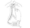
まず、図1乃至図4を参照して第1の実施の形態について説明する。図1及び図2に示すように(図2の左側部分Bは図1の右側部分Aにつながる)、バルーンカテーテル1は、互いにスライド可能な外筒シャフト2と内筒シャフト3とからなるカテーテルシャフト4と、膨張した状態で標的病変部に接触可能な形状を有する外筒シャフト2の先端部と内筒シャフト3の先端部近傍との間に設置された収縮膨張可能なバルーン6と、バルーン6内に配設され高周波通電用電極8と、高周波通電用電極8に電気的に接続されるリード線10と、バルーン6内の温度をモニターするためにバルーン4内に配設された熱電対12と、バルーン6内に導入される液体の温度をバルーン6内で均一化する温度均一化手段としての撹拌手段14とを備えている。
【0034】
内筒シャフト3の内側にはカテーテルシャフト4を案内するためのガイドワイヤ16が挿通して設けられている。カテーテルシャフト4の軸線はガイドワイヤ16にほぼ一致している。
【0035】
内筒シャフト4のバルーン6内にある先端部近傍にはカテーテルシャフト4の軸線に対し回転可能に配設された前部回転子20が配設されており、外筒シャフト2内の先端部近傍にはカテーテルシャフト4の軸線に対し回転可能に配設された後部回転子21が配設されている。
【0036】
高周波通電用電極8は、前部回転子20と後部回転子21との間に互いに並列に接続された複数のスプライン状線部8aから構成されている。高周波通電用電極8を構成するスプライン状線部8aは、外筒シャフト2と内筒シャフト3とを互いにスライドさせてバルーン6を膨張させると、直線状の形状から、図1に示すようにバルーン6の内壁面に沿った弓状形状に形状変化可能に形成されている。
【0037】
外筒シャフト2の後端部の近傍にはカテーテルシャフト4の軸線に対し回転可能に基部回転子23が配設されている。基部回転子23の一端にはリング体24が設けられ、他端近傍にはリング電極25が設けられ、リング体24とリング電極25の間には回転駆動用の歯車26が設けられている。リング電極25の外側にはパンタグラフ状の端子29が設けられており、リング電極25は端子29に接触を保持しながら回転可能である。
【0038】
外筒シャフト2の端部には雄ねじ31が形成されており、フランジ32がOリング27、27を介在させて雄ねじ31に取り付けられる。Oリング27、27は、基部回転子23が回転可能に基部回転子23の外周面にゆるく締め付けられており、外筒シャフト2の内壁と基部回転子23の外周面との間の隙間から液体が漏れないようにする。このようにして、基部回転子23と外筒シャフト2との間、および基部回転子23と内筒シャフト3との間の隙間をパッキングを有することにより、水漏れ防止活栓の機能が果たされる。
【0039】
前部回転子20と後部回転子21と基部回転子23の内側には内筒シャフト3が貫通している。
【0040】
基部回転子23の端部には雄ねじ31が形成されており、フランジ34がOリング28を介在させて雄ねじ33に取り付けられる。Oリング28は、内筒シャフト3の外周面と基部回転子23の内壁との間の隙間から液体がが漏れないようにする。
【0041】
リード線10は、螺旋状に形成されている。リード線10の一端は後部回転子21に接続され、他端側は基部回転子23のリング体24に接続されるとともにリング電極25に接続されている。リング電極25の外側の端子29は、高周波発生器40に電気的に接続されている。高周波発生器40によってリード線10を介して高周波通電用電極8に高周波電力が供給される。
【0042】
高周波発生器40によって、例えば13.56MHzの高周波電力が高周波通電用電極8と対極板53との間に供給され、例えば、バルーン6の直径が約2.5cmの場合には200W乃至400Wの高周波電力が供給される。高周波通電用電極8と体表面の対極板53との間に高周波通電すると、バルーン6と接触する組織18は高周波誘電可熱をともなった容量型加熱により焼灼され、この結果、いわゆる高周波誘導型加熱の原理に従って異なる誘電率を有する誘電体が接触する部分が加熱され、バルーン6と接触する組織18が加熱され焼灼される。
【0043】
歯車26の近傍には、内部に歯車36,37を収納したギアボックス35とモータ38が配設されている。モータ38によって歯車36,37を介して減速されて歯車26が駆動される。モータ38は、所定の回数だけ一方向に回転するように制御してもよいが、時計方向と反時計方向とを交互に例えば2回転ずつ回動するように制御してもよい。
【0044】
リード線10はある程度の剛性の有する材料で形成されている。モータ38によって歯車26を介して基部回転子23が回動駆動されると、リード線10がリング体24に接続されていることによってモータ38による回転エネルギーはリード線10に伝達可能であり、これによって、後部回転子21と前部回転子20が回動駆動され、高周波通電用電極8を回転させることができる。
【0045】
モータ38が所定の回数だけ一方向にリード線10を回転させる場合、リード線10を螺旋状に巻かれた方向と反対方向に回転させるようにする。所定回転数だけ回転させた後にモータ38の駆動を解除することにより、リード線10は元に状態に戻るように逆方向に回転する。このようにモータ38の駆動をON/OFFすることにより、高周波通電用電極8は時計方向と反時計方向とを交互に回転する。
【0046】
また、モータ38が時計方向と反時計方向とを交互に例えば2回転ずつ回転するように制御される場合には、リード線10を螺旋状ではなく直線状に形成しバネ弾性を有する材料で構成することによって、高周波通電用電極8を時計方向と反時計方向とに交互に回転させることができる。
【0047】
このように、温度均一化手段としての撹拌手段14は、高周波通電用電極8を回転駆動するために、前部回転子20、後部回転子21、基部回転子23及びモータ38等から構成されている。
【0048】
上述のように、リード線10は、モータ38による回転エネルギーを高周波通電用電極8に伝達するとともに、高周波発生器40による高周波電力を高周波通電用電極8に伝達する。
【0049】
外筒シャフト2の後端部近傍には、分岐管51が設けられており、分岐管51は空気抜き用部と造影剤注入用部との二方栓に形成されている。分岐管51を空気抜き用部に切り替えてバルーン6内の空気を抜いた後、造影剤注入用部に切り替えてバルーン6を膨張させるために生理食塩水等の液体がバルーン内に導入される。
【0050】
内筒シャフト3は2ルーメンを有し、1つのルーメンはガイドワイアー16や薬液注入用であり、もう一方のルーメンはバルーン6内の内筒シャフト3の中央に設置された温度センサーとしての熱電対12からの情報をつたえる導線を設けるものでる。
【0051】
バルーン6内も液体の温度は内筒シャフト3内に設けられた熱電対12によって検出される。熱電対12は内筒シャフト3内を通ってカテーテルシャフト4外に導かれ、温度計42に接続され、温度計42によってモニターしたバルーン6内の温度が表示される。
【0052】
バルーン6は、抗血栓性を有するとともに耐熱性であって弾力性を有するレジンで形成されている。図1に示すバルーン6は、膨張した状態でバスケット形状あるいはタマネギ形状を有する。
【0053】
高周波通電用電極8は等間隔に配設された数本から数十本のスプライン状線部8aで構成されている。内筒シャフト3と外筒シャフト2をスライドさせ前部回転子20と後部回転子21との間隔を短縮すると、スプライン状線部8aは直線状から弓状となり、スプライン状線部8aは全体としてバスケット形状あるいはタマネギ形状の高周波通電用電極8を形成する。スプライン状線部8aは、形状記憶合金によって形成することによって、直線状の形状と弓状形状との間で確実が形状変化が可能になる。
【0054】
スプライン状線部8aの先端部および後端部は樹脂コーティングされており、これによって、スプライン状線部8aの先端部および後端部が過度に高周波加熱されることを防止する。
【0055】
高周波発生器40によってMHz以上(例えば13.56MHz)の周波数帯の高周波電力を供給することにより、患者の背部の体表面に配設される対極板53(図3参照)と高周波通電用電極8との間で容量型高周波加熱を生じさせることができる。
【0056】
バスケット形状の高周波通電用電極8は螺旋状のリード線10によって基部回転子23のリング電極25に接続され、回転するリング電極25と高周波発生器40からの導線末端部との間はパンタグラフ状の端子29を介して常時接触しており、高周波通電用電極8に高周波電流が供給される。高周波通電用電極8が回転することによって、高周波通電用電極8が固定されている場合に比べて、均等な高周波電界を周囲に対して放射することができる。
【0057】
モータ38による回転はギアボックス35を介して減速され、歯車26を介して基部回転子23に伝達され、基部回転子23の回転はリード線10を介して後部回転子21に伝達され、バルーン6内のスプライン状線部8aを回転させる。膨張したバルーン6内を満たす液体はこの回転により攪拌され、バルーン6内において対流熱により生じる温度むらを無くし、温度の均一化を図ることができる。このように、バルーン6内の液体を攪拌することによってバルーン6の中心部温度とバルーン6の周辺部温度とバルーン6と接触する組織18の温度とをほぼ同一にすることができる。これによって、モニターするバルーン6の中心部温度を温度計42によって表示し、表示された温度を参照することによって、表示された温度をバルーン6と接触する組織18の正確な温度として把握することができる。
【0058】
バルーン6内の内筒シャフト3の中央部に配設した熱電対12によって、高周波通電用電極8に高周波電力を通電中の温度をモニターし、バルーン6内の液体が至適温度になるように、フィードバック回路によって高周波発生器40の出力を調節する。これによって、バルーン6と接触する組織18を至適温度で加温することができる。
【0059】
このように、回転するバスケット形状の高周波通電用電極8により、より均一な高周波電界の放射を可能にするとともに、バルーン6内の液体を攪拌することによってバルーン6の液体の温度を均一化しバルーン6と接触する組織18の温度を正確に得ることが可能になる。
【0060】
次に、上述したバルーンカテーテル1を心房細動治療用の肺静脈に適用し、電気的隔離用のバルーンとして使用する例について説明する。
【0061】
図3はバルーンカテーテル1による肺静脈17の肺静脈口17aの周囲の心房19側の組織18をアブレーション(灼熱)する場合を示す。
【0062】
施行法としては、バルーン6内を外筒シャフト2の分岐管51の注入口より何度も生理食塩水で注入吸引をくりかえして空気抜きを行う。
【0063】
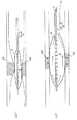
図4(a)に示すように、バルーンカテーテル1を肺静脈17の血管へ挿入する時はバルーン6を収縮させながら内筒シャフト3をスライドさせて前方に限界までおしだす。このとき前部回転子20と後部回転子21との間もひろがるので、スプライン状線部8aも弓形から直線状形状となり、バルーン6の径は最小となる。この状態でバルーン6を血管内へ挿入する。バルーンカテーテル1を操作して、標的組織18に近づけたところで、図4(b)に示すように内筒シャフト3をひきながらバルーン6に分岐管51から造影剤と生理食塩水を注入して拡張させると、前部回転子20と後部回転子21との間の間隔も短縮するのでスプライン状線部8aは弓状となり、高周波通電用電極8は全体としてバルーン6内にバスケット型を形成する。さらにカテーテル1を細かく操作してバルーンを標的組織18に接触させる。
【0064】
次に、モータ38の電源をいれると、ギアボックス35を介して減速された回転が基部回転子23につたわる。この回転エネルギーはカテーテルシャフト4内をとおるラセン状リード線10を介して外筒シャフト3の先端部の後部回転子21につたわり、バルーン6内のバスケット型の高周波通電用電極8が回転し、バルーン6内の液体を攪拌する。
【0065】
次に、高周波発生器40より周波数の高い、例えば13.56MHzの高周波電流を背部の対極板53とカテーテル1のバスケット型の高周波通電用電極8へつながるリング電極25との間に供給する。高周波電流は回転するリング電極25と接触する端子29を介して供給される。
【0066】
バルーン6内を回転するバスケット型の高周波通電用電極8に高周波電流が流れると、誘電過熱をともなう容量型加熱が生じ、バルーン6およびバルーン6と接触する組織18が高周波加熱される。バルーン6内温度分布は通常であれば,対流熱により上が高く下が低いが、バルーン6内の液体はバスケット型の高周波通電用電極8の回転により攪拌されて、均一な温度となる。
【0067】
また、バルーン6内に電極が固定されていると電極位置によって温度分布にむらが生じるが、本実施形態では高周波通電用電極8は回転しているので、周囲に対してより均一な高周波電界を放射することができる。
【0068】
これらのためバルーン6内だけでなくバルーンと接触する組織もより均一に高周波加温される。
【0069】
スプライン状線部8aの集まる回転子20,21の近傍では、より過熱するおそれがあるが、回転子20,21自体を樹脂やセラミックなどの誘電係数の低い物質で形成することや、スプラインの一部を樹脂コーティングすることや内筒内を冷却水で環流することによって、過熱を防ぐことができる。
【0070】
このように、肺静脈17周囲の心房19側を円周状に均等にアブレーションすることにより、肺静脈17を電気的に隔離して肺静脈起源の心房細動を安全に治療することができる。
【0071】
次に、本発明の他の第2の実施形態について説明する。
【0072】
本実施形態に係るバルーンカテーテル1は、バルーン6内に導入される液体の温度をバルーン6内で均一化する温度均一化手段は、バルーン6内の液体の温度を均一化するように液体をバルーン6内で潅流させる潅流手段60で構成されている。
【0073】
バルーン6内の内筒シャフト3の先端部近傍には、複数の小孔ノズル64が形成されている。潅流手段60は、内筒シャフト3内へ送る液体の温度を例えば37℃に温度制御する温度制御手段66と、温度制御手段66で温度制御された液体を内筒シャフト3内へ送入し、小孔ノズル64からバルーン6内に噴出した液体を外筒シャフト2の内壁先端部と内筒シャフト2の外壁との間を経て吸引させる液体送り手段62を備えている。バルーン6は、膨張した状態でラグビーボール状の形状を有する。
【0074】
高周波通電用電極8はバルーン6内の内筒シャフト3の外周に巻設されている。高周波通電用電極8にリード線10を介して高周波発生器40から高周波電流が供給される。高周波通電用電極8に供給される高周波電力は、熱電対12によって温度をモニターしながら前述の実施例と同様に制御される。
【0075】
図5に示すように、温度制御手段66によって例えば37℃に温度制御された潅流液体70は、バルーン6内の内筒シャフト3内を通る間に加熱され、複数の小孔ノズル64からは44℃の液体として噴出され、バルーン6内でほぼ均一に43.5℃なり、外筒シャフト2の内壁先端部と内筒シャフト2の外壁との間の端部では43℃になる。このようにして、潅流手段60によって潅流液体70を潅流させることによってバルーン6内の液体の温度はほぼ43.5℃の温度に均一化される。
【0076】
図5に示すバルーンカテーテル1を図7に示すように動脈硬化病変部68に対し適用した例を以下に説明する。
【0077】
図6(a)に示すようにバルーン6の収縮した状態で大腿動脈より挿入されたバルーンカテーテル1は、頚動脈病変部68にバルーン6を接触させる。この位置で外筒シャフト2の分岐管51より造影剤と生食を注入すると、図6(b)に示すように、バルーン6は膨張し狭窄部を拡張する。この状態で、高周波通電用電極8と背部の対極板53との間で13.56MHzの高周波通電を開始する。
【0078】
また、潅流手段60によって、例えば37℃に温度制御した潅流流体70を内筒シャフト3のルーメンを介して加圧注入すると、バルーン6内の内筒シャフト3先端部の小孔ノズル64より同心円状に高周波加温された温水が噴出し,バルーン6内を環流してバルーン6内温度を均一化した後外筒シャフト2のルーメンより排出される。バルーン6の温度を43.5℃に設定して20分以上加温すると、バルーン6と接触する動脈硬化病変部68内のマクロファージなどの炎症細胞はアポトーシスをおこして、動脈硬化病変の安定化につながる。次にバルーン6を収縮させて、バルーンカテーテル1を抜去する。
【0079】
以上のように、本実施の形態によれば、均等に至適温度に組織68を加温できるため、動脈硬化病変部68を例えば43℃で20分以上加温することで、内皮細胞のような正常組織に影響をあたえず、不安定化因子であるマクロファージなどの炎症細胞のアポトーシスをおこし、動脈硬化病変部68を安定化させることができる。
【0080】
また、ガンの局所的な温熱療法にも適応することができ、例えば、ガン細胞も20分以上の43℃の加温により抑制ないし消滅することが確認されている。
【0081】
図8は、さらに他の実施形態を示す図である。
【0082】
本実施形態に係るバルーンカテーテル1は、バルーン6内に導入される液体の温度をバルーン6内で均一化する温度均一化手段は、液体をバルーン内で撹拌する撹拌手段80である。
【0083】
撹拌手段80は、外筒シャフト2の内壁と内筒シャフト3の外壁との間の流路83に連通する連結管82と、連結管82内及び流路83に満たされた液体に振動を印加する振動発生ポンプ等の振動発生手段81とを備えている。連結管82は、外筒シャフト2に分岐して連結されている。連結管82内の液体は流路83の液体及びバルーン6内の液体に連通しており、振動発生手段81によって例えば約1Hzの振動を印加すると、連結管82内の液体は流路83の液体には振動波86が伝搬する。この結果、バルーン6内の液体には渦流85を生じさせることができる。渦流85はバルーン6内をランダムな方向に形成され、バルーン6内の液体の温度の均一化を図ることができる。この結果、血管内の挿入されたバルーン6内の液体の温度の均一化を図ることができる。これによって、組織68に形成されたアテロームを至適温度で加温することが可能になる。
【0084】
振動発生手段81としては、連結管82内の液体に接触する振動面を有するダイアフラグポンプ等を採用することができる。
【0085】
高周波加熱については、図5に示す場合と同様にに内筒シャフト3に螺旋状に巻かれた高周波通電用電極8によって行われる。
【0086】
バルーン6を適度の弾性を有する材料で形成することにより、振動発生手段81による振動を振動波86を介して、バルーン6内の液体に好適な渦流を生成することができる。
【0087】
【発明の効果】
以上説明したように、本発明の構成によれば、バルーンと接触する組織を均等に至適温度で高周波加温することができる。この結果、血栓形成や組織の蒸散による潰瘍化なく、貫壁性の壊死層を三次元的に安全に形成することができる。これによって、全ての肺静脈のアイソレーションや線状焼灼によるブロックラインによる心房粗動の治療が安全確実となり、,心房細動の根治治療が可能となる。
【0088】
また。均等に至適温度に組織を加温できるため、例えば、動脈硬化病変を所定温度に加温することで、内皮細胞のような正常組織に影響をあたえず、不安定化因子であるマクロファージなどの炎症細胞のアポトーシスをおこし、動脈硬化病変を安定化させることができる。
【図面の簡単な説明】
【図1】本発明の高周波加温バルーンカテーテルの一実施形態の一部を示す図。
【図2】図1に示すバルーンカテーテルの一部につながる部分を示し、図1の右側部に図2の左側部が続く。
【図3】バルーンカテーテルを心房細動治療用の肺静脈に適用し、電気的隔離用のバルーンとして使用する例を示す図。
【図4】バルーンを収縮した状態で肺静脈の血管へ挿入することを示す図(a)と、標的組織に近づけたところで、バルーンを膨張させた状態を示す図(b)。
【図5】本発明の高周波加温バルーンカテーテルの他の実施形態の一部を示す図。
【図6】バルーンを収縮した状態で大腿動脈より挿入することを示す図(a)と、標的組織に近づけたところで、バルーンを膨張させた状態を示す図(b)。
【図7】バルーンカテーテルを動脈硬化病変部に対し適用した例を説明する図。
【図8】本発明の高周波加温バルーンカテーテルの他の実施形態の一部を示す図。
【符号の説明】
1 バルーンカテーテル
2 外筒シャフト
3 内筒シャフト
4 カテーテルシャフト
6 バルーン
8 高周波通電用電極
8a スプライン状線部
10 リード線
12 温度センサー
14 撹拌手段
18 組織(標的病変部)
20 前部回転子
21 後部回転子
23 基部回転子
26 リング電極
38 モータ
40 高周波発生器
42 温度計
53 対極板
60 潅流手段
62 液体送り手段
64 小孔ノズル
66 温度制御手段
68 動脈硬化病変部
80 撹拌手段
81 振動発生ポンプ
82 連結管
83 流路
86 振動波[0001]
BACKGROUND OF THE INVENTION
The present invention relates to a high-frequency warming balloon catheter, and more particularly, to a high-frequency thermotherapy balloon catheter used for treating cardiovascular diseases.
[0002]
[Prior art]
There is a method for treating a lesion such as an arrhythmia source or arteriosclerosis by arranging a high-frequency energizing electrode inside a contractible balloon and radiating a high-frequency electric field from here to heat the tissue in contact with the balloon. (For example, Japanese Patent No. 2538375, Japanese Patent No. 2510428, and Japanese Patent No. 2574119 by the present applicant).
[0003]
In order to warm the tissue in contact with the balloon and treat it well, it is necessary to warm the tissue at as uniform a temperature as possible.
[0004]
[Problems to be solved by the invention]
The high-frequency energizing electrode disposed in the balloon cannot be disposed completely and uniformly in the balloon.
[0005]
In a conventional high-frequency warming balloon catheter, heat is generated unevenly due to the shape of the electrode disposed in the balloon, and heat convection is generated in the liquid in the balloon. There is a problem that temperature unevenness cannot be avoided, and the tissue in contact with the balloon cannot be heated to a uniform temperature.
[0006]
Accordingly, an object of the present invention is to eliminate the above-mentioned problems of the prior art, perform high-frequency heating that can heat the tissue in contact with the balloon as uniformly as possible and heat-treat the affected area safely at the optimum temperature. It is to provide a warm balloon catheter.
[0007]
[Means for Solving the Problems]
In order to achieve the above object, the high-frequency warming balloon catheter of the present invention has a catheter shaft composed of an outer tube shaft and an inner tube shaft that are slidable with each other, and a shape that can contact a target lesion in an expanded state. The balloon capable of transmitting high-frequency power between a contractible and inflatable balloon installed between the distal end portion of the outer cylindrical shaft and the vicinity of the distal end portion of the inner cylindrical shaft, and a counter electrode disposed on the body surface A high-frequency energizing electrode disposed in the wall of the balloon or in the balloon, a lead wire electrically connected to the high-frequency energizing electrode, a temperature sensor capable of monitoring the temperature in the balloon, and the balloon Temperature equalizing means for equalizing the temperature of the introduced liquid in the balloon;The temperature equalizing means is an agitating means for agitating the liquid in the balloon, and the agitating means includes a rotation driving means for driving the high-frequency energizing electrode to be rotatable. It is characterized by that.
[0008]
By equalizing the temperature of the liquid introduced into the balloon by the temperature equalizing means in the balloon, the temperature of the liquid in the balloon can be prevented from becoming non-uniform due to convection and the like, and the target lesion contacting the balloon The whole part can be heated at high frequency at a uniform temperature. In addition, since the temperature of the liquid in the balloon can be made uniform, it becomes possible to accurately match the temperature in the balloon monitored by the temperature sensor and the temperature of the target lesion that is heated by the high frequency sensor, The temperature of the target lesion can be accurately controlled.
[0010]
The temperature of the liquid in the balloon can be easily equalized by the stirring means.
[0011]
Further, a front rotor disposed in the vicinity of the distal end portion of the inner cylindrical shaft so as to be rotatable with respect to the axis of the catheter shaft, and a rotatable in the vicinity of the distal end portion of the outer cylindrical shaft with respect to the axis of the catheter shaft. A rear rotor that is disposed; and a base rotor that holds the lead wire in a high-frequency manner so that the lead wire can rotate, and the high-frequency current-carrying electrode includes a front rotor and a rear rotor. Connected in parallel with each other,The rotation driving means is The high-frequency energizing electrode, the front rotor, the rear rotor, the lead wire, and the base rotor are rotatably driven.
[0012]
The high frequency energizing electrode, the front rotor, the rear rotor, the lead wire, and the base rotor are driven to rotate by the rotation driving means of the agitating means, so that the high frequency energizing electrode can be rotated in a state where high frequency energization is possible It can be driven. As a result, uniform high-frequency energization can be performed, and the temperature in the balloon can be made uniform by stirring by rotation of the high-frequency energization electrode.
[0013]
In addition, the high-frequency energizing electrode includes a plurality of spline-like line portions connected in parallel to each other between the front rotor and the rear rotor.
[0014]
The high-frequency energizing electrode can be easily configured and can be uniformly distributed in the balloon.
[0015]
Further, the spline-like line portion constituting the high-frequency energizing electrode slides along the inner wall surface of the balloon from a linear shape when the balloon is inflated by sliding the outer cylinder shaft and the inner cylinder shaft with each other. It is formed so that the shape can be changed to an arcuate shape
It is characterized by that.
[0016]
By rotating the high-frequency energizing electrode into an arcuate shape, the liquid in the balloon can be efficiently stirred and high-frequency power can be radiated uniformly.
[0017]
Further, the lead wire is formed in a spiral shape, and the rotation driving means rotates the lead wire to rotate the high-frequency energizing electrode.
[0018]
Since the lead wire is formed in a spiral shape, for example, when it is rotated in one direction, if it stops rotating drive, it can rotate in the opposite direction due to its elasticity and can return to the original state easily. Rotation can be performed.
[0019]
In addition, the rotation driving means rotates the front rotor, the rear rotor, the lead wire, and the base rotor by alternately changing the rotation direction at every predetermined number of rotations. The liquid in the balloon can be agitated by the high-frequency energizing electrode by alternately changing the rotation direction with a simple configuration.
[0020]
Also, mutualA catheter shaft comprising a slidable outer tube shaft and an inner tube shaft, a distal end portion of the outer tube shaft and a vicinity of the distal end portion of the inner tube shaft having a shape capable of contacting a target lesion in an expanded state A high-frequency energizing electrode disposed in the wall of the balloon or in the balloon capable of transmitting a high-frequency power between a contractible and inflatable balloon disposed between and a counter electrode disposed on the body surface; A lead wire electrically connected to the electrode for high-frequency energization, a temperature sensor capable of monitoring the temperature in the balloon, and temperature uniformity for equalizing the temperature of the liquid introduced into the balloon in the balloon And the temperature equalizing means is a stirring means for stirring the liquid in the balloon, The agitating means communicates with a flow path between an inner wall of the outer cylinder shaft and an outer wall of the inner cylinder shaft, communicates with the inside of the balloon, and is connected to the outer cylinder shaft; Vibration generating means for applying vibration to the liquid filled in the flow path.
[0021]
By applying vibration to the liquid filled in the connecting pipe and the flow path by the vibration generating means and propagating the vibration wave to the liquid in the balloon, the liquid in the balloon is agitated to make the temperature uniform.
[0022]
The vibration generating means applies vibration to the liquid filled in the connection pipe and the flow path so that a vortex is formed in the liquid in the balloon.
[0023]
By generating a vortex in the liquid in the balloon, the temperature can be made uniform efficiently.
[0024]
Further, the temperature equalizing means is a perfusion means for perfusing the liquid in the balloon so as to equalize the temperature of the liquid in the balloon.
[0025]
For example, the temperature of the liquid in the balloon can be made uniform by perfusing liquid with a constant temperature by the perfusion means.
[0026]
A plurality of small holes are formed in the inner cylinder shaft in the balloon, and the perfusion means feeds the liquid into the inner cylinder shaft and ejects the liquid from the small holes into the balloon. The liquid feeding means for sucking the liquid through the space between the inner wall of the outer cylinder shaft and the outer wall of the inner cylinder shaft is provided.
[0027]
The liquid feeding means can eject the liquid from the small hole, and can collect and perfuse the liquid through a flow path between the inner wall of the outer cylinder shaft and the outer wall of the inner cylinder shaft.
[0028]
Further, the high-frequency energization electrode is spirally wound around an outer wall of the inner cylindrical shaft in the balloon.
[0029]
The high-frequency energizing electrode can be easily disposed in the balloon, and high-frequency heating can be performed efficiently.
[0030]
The balloon is made of a resin that is antithrombotic, heat resistant, and elastic.
[0031]
The characteristics required for the balloon can be satisfied sufficiently.
[0032]
DETAILED DESCRIPTION OF THE INVENTION
Embodiments of a pulmonary vein high-frequency warming balloon catheter according to the present invention will be described below with reference to the accompanying drawings.
[0033]
First, a first embodiment will be described with reference to FIGS. As shown in FIGS. 1 and 2 (the left portion B in FIG. 2 is connected to the right portion A in FIG. 1), the
[0034]
A
[0035]
In the vicinity of the distal end portion of the inner
[0036]
The high-
[0037]
A
[0038]
A
[0039]
The
[0040]
A
[0041]
The
[0042]
The
[0043]
In the vicinity of the
[0044]
The
[0045]
When the
[0046]
Further, when the
[0047]
As described above, the stirring means 14 as the temperature equalizing means includes the
[0048]
As described above, the
[0049]
A
[0050]
The
[0051]
The temperature of the liquid in the
[0052]
The
[0053]
The high-
[0054]
The front end portion and the rear end portion of the spline-
[0055]
By supplying high frequency power in a frequency band of MHz or higher (for example, 13.56 MHz) by the
[0056]
The basket-shaped high-
[0057]
The rotation by the
[0058]
A
[0059]
As described above, the rotating basket-shaped high-
[0060]
Next, an example in which the above-described
[0061]
FIG. 3 shows a case where the
[0062]
As an enforcement method, the inside of the
[0063]
As shown in FIG. 4A, when the
[0064]
Next, when the power source of the
[0065]
Next, a high-frequency current having a frequency higher than that of the high-
[0066]
When a high-frequency current flows through the basket-type high-
[0067]
In addition, when the electrode is fixed in the
[0068]
For this reason, not only the inside of the
[0069]
In the vicinity of the
[0070]
In this way, by uniformly ablating the side of the
[0071]
Next, another second embodiment of the present invention will be described.
[0072]
In the
[0073]
A plurality of
[0074]
The high
[0075]
As shown in FIG. 5, the
[0076]
An example in which the
[0077]
As shown in FIG. 6A, the
[0078]
Further, when the
[0079]
As described above, according to the present embodiment, the
[0080]
It can also be applied to local hyperthermia for cancer. For example, it has been confirmed that cancer cells are suppressed or disappeared by heating at 43 ° C. for 20 minutes or more.
[0081]
FIG. 8 is a diagram showing still another embodiment.
[0082]
In the
[0083]
The stirring means 80 applies vibrations to the connecting
[0084]
As the vibration generating means 81, a diaphragm pump or the like having a vibration surface in contact with the liquid in the connecting
[0085]
The high frequency heating is performed by the high
[0086]
By forming the
[0087]
【The invention's effect】
As described above, according to the configuration of the present invention, the tissue that comes into contact with the balloon can be heated at a high frequency evenly at the optimum temperature. As a result, a transmural necrotic layer can be safely formed in three dimensions without thrombosis or ulceration due to tissue evaporation. This makes it possible to safely and reliably treat atrial flutter by block lines using all pulmonary vein isolation and linear cauterization, and enables radical treatment of atrial fibrillation.
[0088]
Also. Since tissue can be uniformly heated to the optimum temperature, for example, by heating arteriosclerotic lesions to a predetermined temperature, normal tissues such as endothelial cells are not affected, and macrophages that are destabilizing factors It can induce apoptosis of inflammatory cells and stabilize arteriosclerotic lesions.
[Brief description of the drawings]
FIG. 1 shows a part of an embodiment of a high-frequency warming balloon catheter of the present invention.
2 shows a portion connected to a part of the balloon catheter shown in FIG. 1, and the right side of FIG. 1 is followed by the left side of FIG.
FIG. 3 is a view showing an example in which a balloon catheter is applied to a pulmonary vein for treating atrial fibrillation and used as a balloon for electrical isolation.
FIG. 4A is a diagram illustrating insertion into a pulmonary vein blood vessel in a deflated state, and FIG. 4B is a diagram illustrating a state in which the balloon is inflated when approaching a target tissue.
FIG. 5 is a view showing a part of another embodiment of the high-frequency warming balloon catheter of the present invention.
FIG. 6A is a diagram showing insertion from a femoral artery in a deflated state, and FIG. 6B is a diagram showing a state in which the balloon is inflated when approaching a target tissue.
FIG. 7 is a diagram illustrating an example in which a balloon catheter is applied to an arteriosclerotic lesion.
FIG. 8 is a view showing a part of another embodiment of the high-frequency warming balloon catheter of the present invention.
[Explanation of symbols]
1 Balloon catheter
2 Outer cylinder shaft
3 Inner cylinder shaft
4 Catheter shaft
6 Balloon
8 Electrode for high-frequency energization
8a Spline line part
10 Lead wire
12 Temperature sensor
14 Stirring means
18 tissues (target lesions)
20 Front rotor
21 Rear rotor
23 Base rotor
26 Ring electrode
38 motor
40 High frequency generator
42 Thermometer
53 Counter electrode
60 Perfusion means
62 Liquid feeding means
64 Small hole nozzle
66 Temperature control means
68 Arteriosclerotic lesion
80 Stirring means
81 Vibration generating pump
82 Connecting pipe
83 Flow path
86 Vibration wave
Claims (10)
Translated fromJapanese膨張した状態で標的病変部に接触可能な形状を有する前記外筒シャフトの先端部と前記内筒シャフトの先端部近傍との間に設置された収縮膨張可能なバルーンと、
体表面に配設される対極との間で高周波電力を伝送可能な前記バルーンの壁内又はバルーン内に配設された高周波通電用電極と、
前記高周波通電用電極に電気的に接続されるリード線と、
前記バルーン内の温度をモニター可能な温度センサーと、
前記バルーン内に導入される液体の温度を前記バルーン内で均一化する温度均一化手段と、
を備え、
前記温度均一化手段は、前記液体を前記バルーン内で撹拌する撹拌手段であり、
前記撹拌手段は、前記高周波通電用電極を回転可能に駆動する回動駆動手段を備える
ことを特徴とする高周波加温バルーンカテーテル。A catheter shaft comprising an outer tube shaft and an inner tube shaft slidable with respect to each other;
A contractible and inflatable balloon installed between the distal end portion of the outer cylindrical shaft and the vicinity of the distal end portion of the inner cylindrical shaft having a shape capable of contacting a target lesion in an expanded state;
A high-frequency energizing electrode disposed in the wall of the balloon or in the balloon capable of transmitting high-frequency power to and from a counter electrode disposed on the body surface;
A lead wire electrically connected to the high-frequency energizing electrode;
A temperature sensor capable of monitoring the temperature in the balloon;
Temperature equalizing means for equalizing the temperature of the liquid introduced into the balloon in the balloon;
Equipped witha,
The temperature uniformizing means is a stirring means for stirring the liquid in the balloon,
The high-frequency warming balloon catheter characterized in that theagitation unit includes a rotation drive unit that rotatably drives the high-frequency energization electrode .
前記外筒シャフトの先端部近傍に前記カテーテルシャフトの軸線に対し回転可能に配設された後部回転子と、
前記リード線を高周波通電可能であって回転可能に保持する基部回転子と、
を備え、
前記高周波通電用電極は、前部回転子と前記後部回転子との間に互いに並列に接続されており、
前記回動駆動手段は、
前記高周波通電用電極、前記前部回転子、前記後部回転子、前記リード線及び前記基部回転子を回転可能に駆動する
ことを特徴とする請求項2に記載の高周波加温バルーンカテーテル。A front rotor disposed in the vicinity of the distal end portion of the inner cylinder shaft so as to be rotatable with respect to the axis of the catheter shaft;
A rear rotor disposed so as to be rotatable with respect to the axis of the catheter shaft in the vicinity of the distal end portion of the outer cylinder shaft;
A base rotor for holding the lead wire in high-frequency electricity and rotatably;
With
The high-frequency energizing electrodes are connected in parallel between the front rotor and the rear rotor,
The rotation driving means is
The high-frequency warming balloon catheter according to claim 2, wherein the high-frequency energizing electrode, the front rotor, the rear rotor, the lead wire, and the base rotor are rotatably driven.
ことを特徴とする請求項2に記載の高周波加温バルーンカテーテル。3. The high-frequency warming balloon catheter according toclaim 2 , wherein the high-frequency energizing electrode includes a plurality of spline-like line portions connected in parallel with each other between the front rotor and the rear rotor. .
ことを特徴とする請求項3に記載の高周波加温バルーンカテーテル。The spline-like line portion constituting the high-frequency energizing electrode has a bow extending from a linear shape along the inner wall surface of the balloon when the balloon is inflated by sliding the outer cylinder shaft and the inner cylinder shaft with each other. 4. The high-frequency warming balloon catheter according toclaim 3 , wherein the high-frequency warming balloon catheter is formed so as to be changeable in shape.
前記回動駆動手段は、前記リード線を回転させて、前記高周波通電用電極を回転させることを特徴とする請求項2に記載の高周波加温バルーンカテーテル。The lead wire is formed in a spiral shape,
The high-frequency warming balloon catheter according toclaim 2 , wherein the rotation driving unit rotates the high-frequency energization electrode by rotating the lead wire.
ことを特徴とする請求項3に記載の高周波加温バルーンカテーテル。The rotation driving means rotates the front rotor, the rear rotor, the lead wire, and the base rotor by alternately changing the rotation direction at every predetermined number of rotations. The high-frequency warming balloon catheter described.
膨張した状態で標的病変部に接触可能な形状を有する前記外筒シャフトの先端部と前記内筒シャフトの先端部近傍との間に設置された収縮膨張可能なバルーンと、
体表面に配設される対極との間で高周波電力を伝送可能な前記バルーンの壁内又はバルーン内に配設された高周波通電用電極と、
前記高周波通電用電極に電気的に接続されるリード線と、
前記バルーン内の温度をモニター可能な温度センサーと、
前記バルーン内に導入される液体の温度を前記バルーン内で均一化する温度均一化手段と、
を備え、
前記温度均一化手段は、前記液体を前記バルーン内で撹拌する撹拌手段であり、
前記撹拌手段は、
前記外筒シャフトの内壁と前記内筒シャフトの外壁との間の流路に連通し前記バルーン内と連通する、前記外筒シャフトに連結された連結管と、
前記連結管及び前記流路に満たされた液体に振動を印加する振動発生手段と、
を備える、
ことを特徴とする高周波加温バルーンカテーテル。A catheter shaft comprising a slidable outer cylindrical shaft and the inner tube shaft each otherphysician,
A contractible and inflatable balloon installed between the distal end portion of the outer cylindrical shaft and the vicinity of the distal end portion of the inner cylindrical shaft having a shape capable of contacting a target lesion in an expanded state;
A high frequency current applying electrode disposed inthe wall of the balloon capable of transmitting high-frequency power ortheBalover downbetween the counter electrode disposed on the bodysurface,
A lead wire electrically connected to the high-frequency energizing electrode;
A temperature sensor capable of monitoring the temperature in the balloon;
Temperature equalizing means for equalizing the temperature of the liquid introduced into the balloon in the balloon;
With
The temperature uniformizing means is a stirring means for stirring the liquid in the balloon,
The stirring means includes
A connection pipe connected to the outer cylinder shaft, communicating with the flow path between the inner wall of the outer cylinder shaft and the outer wall of the inner cylinder shaft, and communicating with the inside of the balloon;
Vibration generating means for applying vibration to the liquid filled in the connecting pipe and the flow path;
Comprising
A high-frequency warming balloon catheter characterized by the above.
ことを特徴とする請求項7に記載の高周波加温バルーンカテーテル。The high-frequency wave according toclaim 7 , wherein the vibration generating means applies vibration to the liquid filled in the connection pipe and the flow path so that a vortex is formed in the liquid in the balloon. Warming balloon catheter.
ことを特徴とする請求項1または請求項7のいずれか1項に記載の高周波加温バルーンカテーテル。8. The high-frequency applying electrode according toclaim 1, wherein the high-frequency energizing electrode is spirally wound around an outer wall of the inner cylinder shaft in the balloon. 9. Warm balloon catheter.
ことを特徴とする請求項1または請求項7のいずれか1項に記載の高周波加温バルーンカテーテル。The high-frequency warming balloon catheter accordingto any one of claims 1 and 7, wherein the balloon is made of a resin that is antithrombotic, heat resistant, and elastic.
Priority Applications (7)
| Application Number | Priority Date | Filing Date | Title |
|---|---|---|---|
| JP2001303112AJP3607231B2 (en) | 2001-09-28 | 2001-09-28 | High frequency heating balloon catheter |
| DE2002605553DE60205553T2 (en) | 2001-09-28 | 2002-06-18 | Radiofrequency thermal balloon catheter |
| US10/173,107US6952615B2 (en) | 2001-09-28 | 2002-06-18 | Radiofrequency thermal balloon catheter |
| AT02013333TATE301970T1 (en) | 2001-09-28 | 2002-06-18 | THERMAL BALLOON CATHETER USING RADIO FREQUENCY |
| EP02013333AEP1297795B1 (en) | 2001-09-28 | 2002-06-18 | Radiofrequency thermal balloon catheter |
| CA002419228ACA2419228C (en) | 2001-09-28 | 2003-02-20 | Radiofrequency thermal balloon catheter |
| TW92103941ATW584552B (en) | 2001-09-28 | 2003-02-25 | Radiofrequency thermal balloon catheter |
Applications Claiming Priority (2)
| Application Number | Priority Date | Filing Date | Title |
|---|---|---|---|
| JP2001303112AJP3607231B2 (en) | 2001-09-28 | 2001-09-28 | High frequency heating balloon catheter |
| CA002419228ACA2419228C (en) | 2001-09-28 | 2003-02-20 | Radiofrequency thermal balloon catheter |
Publications (2)
| Publication Number | Publication Date |
|---|---|
| JP2003102850A JP2003102850A (en) | 2003-04-08 |
| JP3607231B2true JP3607231B2 (en) | 2005-01-05 |
Family
ID=33435794
Family Applications (1)
| Application Number | Title | Priority Date | Filing Date |
|---|---|---|---|
| JP2001303112AExpired - LifetimeJP3607231B2 (en) | 2001-09-28 | 2001-09-28 | High frequency heating balloon catheter |
Country Status (4)
| Country | Link |
|---|---|
| US (1) | US6952615B2 (en) |
| EP (1) | EP1297795B1 (en) |
| JP (1) | JP3607231B2 (en) |
| CA (1) | CA2419228C (en) |
Cited By (4)
| Publication number | Priority date | Publication date | Assignee | Title |
|---|---|---|---|---|
| WO2010113914A1 (en) | 2009-03-31 | 2010-10-07 | 東レ株式会社 | Shaft for balloon-equipped ablation catheter |
| WO2010113913A1 (en) | 2009-03-31 | 2010-10-07 | 東レ株式会社 | Stirring method and ablation catheter system with balloon |
| WO2010134503A1 (en) | 2009-05-21 | 2010-11-25 | 東レ株式会社 | Ablation catheter with balloon, and ablation catheter system with balloon |
| WO2013111341A1 (en)* | 2012-01-27 | 2013-08-01 | 有限会社日本エレクテル | Balloon catheter |
Families Citing this family (265)
| Publication number | Priority date | Publication date | Assignee | Title |
|---|---|---|---|---|
| US6488673B1 (en) | 1997-04-07 | 2002-12-03 | Broncus Technologies, Inc. | Method of increasing gas exchange of a lung |
| US7027869B2 (en) | 1998-01-07 | 2006-04-11 | Asthmatx, Inc. | Method for treating an asthma attack |
| US6634363B1 (en) | 1997-04-07 | 2003-10-21 | Broncus Technologies, Inc. | Methods of treating lungs having reversible obstructive pulmonary disease |
| US7425212B1 (en)* | 1998-06-10 | 2008-09-16 | Asthmatx, Inc. | Devices for modification of airways by transfer of energy |
| US7992572B2 (en) | 1998-06-10 | 2011-08-09 | Asthmatx, Inc. | Methods of evaluating individuals having reversible obstructive pulmonary disease |
| US7921855B2 (en) | 1998-01-07 | 2011-04-12 | Asthmatx, Inc. | Method for treating an asthma attack |
| US7198635B2 (en) | 2000-10-17 | 2007-04-03 | Asthmatx, Inc. | Modification of airways by application of energy |
| US8181656B2 (en)* | 1998-06-10 | 2012-05-22 | Asthmatx, Inc. | Methods for treating airways |
| US6702811B2 (en) | 1999-04-05 | 2004-03-09 | Medtronic, Inc. | Ablation catheter assembly with radially decreasing helix and method of use |
| US8251070B2 (en) | 2000-03-27 | 2012-08-28 | Asthmatx, Inc. | Methods for treating airways |
| US7104987B2 (en) | 2000-10-17 | 2006-09-12 | Asthmatx, Inc. | Control system and process for application of energy to airway walls and other mediums |
| US7756583B2 (en) | 2002-04-08 | 2010-07-13 | Ardian, Inc. | Methods and apparatus for intravascularly-induced neuromodulation |
| US7653438B2 (en) | 2002-04-08 | 2010-01-26 | Ardian, Inc. | Methods and apparatus for renal neuromodulation |
| US20140018880A1 (en) | 2002-04-08 | 2014-01-16 | Medtronic Ardian Luxembourg S.A.R.L. | Methods for monopolar renal neuromodulation |
| US8347891B2 (en) | 2002-04-08 | 2013-01-08 | Medtronic Ardian Luxembourg S.A.R.L. | Methods and apparatus for performing a non-continuous circumferential treatment of a body lumen |
| EP1515775A4 (en) | 2002-05-07 | 2010-03-03 | Oncostim Inc | Method and device for treating concer with electrical therapy in conjunction with chemotherapeutic agents and radiation therapy |
| JP4067976B2 (en)* | 2003-01-24 | 2008-03-26 | 有限会社日本エレクテル | High frequency heating balloon catheter |
| AU2004216229B2 (en)* | 2003-02-21 | 2010-12-09 | Electro-Cat, Llc | System and method for measuring cross-sectional areas and pressure gradients in luminal organs |
| US20040226556A1 (en) | 2003-05-13 | 2004-11-18 | Deem Mark E. | Apparatus for treating asthma using neurotoxin |
| DE202004021953U1 (en) | 2003-09-12 | 2013-06-19 | Vessix Vascular, Inc. | Selectable eccentric remodeling and / or ablation of atherosclerotic material |
| JP4391221B2 (en) | 2003-12-22 | 2009-12-24 | 有限会社日本エレクテル | High frequency heating balloon catheter |
| JP3892438B2 (en) | 2003-12-26 | 2007-03-14 | 株式会社日本メディックス | Heating balloon catheter device and its elastic tube device |
| KR20060115900A (en)* | 2004-01-06 | 2006-11-10 | 도레이 가부시끼가이샤 | Balun catheter |
| US8396548B2 (en) | 2008-11-14 | 2013-03-12 | Vessix Vascular, Inc. | Selective drug delivery in a lumen |
| US9713730B2 (en) | 2004-09-10 | 2017-07-25 | Boston Scientific Scimed, Inc. | Apparatus and method for treatment of in-stent restenosis |
| US20060089637A1 (en) | 2004-10-14 | 2006-04-27 | Werneth Randell L | Ablation catheter |
| US7949407B2 (en) | 2004-11-05 | 2011-05-24 | Asthmatx, Inc. | Energy delivery devices and methods |
| WO2006052940A2 (en) | 2004-11-05 | 2006-05-18 | Asthmatx, Inc. | Medical device with procedure improvement features |
| US20070093802A1 (en)* | 2005-10-21 | 2007-04-26 | Danek Christopher J | Energy delivery devices and methods |
| US8617152B2 (en) | 2004-11-15 | 2013-12-31 | Medtronic Ablation Frontiers Llc | Ablation system with feedback |
| US7201918B2 (en)* | 2004-11-16 | 2007-04-10 | Microvention, Inc. | Compositions, systems and methods for treatment of defects in blood vessels |
| US7468062B2 (en) | 2004-11-24 | 2008-12-23 | Ablation Frontiers, Inc. | Atrial ablation catheter adapted for treatment of septal wall arrhythmogenic foci and method of use |
| US7429261B2 (en)* | 2004-11-24 | 2008-09-30 | Ablation Frontiers, Inc. | Atrial ablation catheter and method of use |
| EP2438877B1 (en) | 2005-03-28 | 2016-02-17 | Vessix Vascular, Inc. | Intraluminal electrical tissue characterization and tuned RF energy for selective treatment of atheroma and other target tissues |
| EP2759276A1 (en) | 2005-06-20 | 2014-07-30 | Medtronic Ablation Frontiers LLC | Ablation catheter |
| AU2006268238A1 (en) | 2005-07-11 | 2007-01-18 | Medtronic Ablation Frontiers Llc | Low power tissue ablation system |
| US8657814B2 (en) | 2005-08-22 | 2014-02-25 | Medtronic Ablation Frontiers Llc | User interface for tissue ablation system |
| EP2010085A1 (en) | 2006-03-31 | 2009-01-07 | Breval S.R.L. | Device and method for the thermal ablation of tumors by means of high-frequency electromagnetic energy under overpressure conditions |
| WO2007113867A1 (en)* | 2006-03-31 | 2007-10-11 | Breval S.R.L. | Device and method for the controlled thermal ablation of tumors by means of high-frequency electromagnetic energy |
| US8019435B2 (en) | 2006-05-02 | 2011-09-13 | Boston Scientific Scimed, Inc. | Control of arterial smooth muscle tone |
| US20070287994A1 (en)* | 2006-06-12 | 2007-12-13 | Pankaj Amrit Patel | Endoscopically Introducible Expandable Bipolar Probe |
| US20070288001A1 (en)* | 2006-06-12 | 2007-12-13 | Pankaj Patel | Endoscopically introducible expandable cautery device |
| US20100114269A1 (en)* | 2006-06-28 | 2010-05-06 | Medtronic Cryocath Lp | Variable geometry balloon catheter and method |
| US9814511B2 (en) | 2006-06-28 | 2017-11-14 | Medtronic Cryocath Lp | Variable geometry cooling chamber |
| US9867530B2 (en) | 2006-08-14 | 2018-01-16 | Volcano Corporation | Telescopic side port catheter device with imaging system and method for accessing side branch occlusions |
| JP5559539B2 (en) | 2006-10-18 | 2014-07-23 | べシックス・バスキュラー・インコーポレイテッド | System that induces desirable temperature effects on body tissue |
| EP2455036B1 (en) | 2006-10-18 | 2015-07-15 | Vessix Vascular, Inc. | Tuned RF energy and electrical tissue characterization for selective treatment of target tissues |
| EP2076198A4 (en) | 2006-10-18 | 2009-12-09 | Minnow Medical Inc | Inducing desirable temperature effects on body tissue |
| US7931647B2 (en)* | 2006-10-20 | 2011-04-26 | Asthmatx, Inc. | Method of delivering energy to a lung airway using markers |
| JP4226040B2 (en)* | 2007-01-12 | 2009-02-18 | 有限会社日本エレクテル | High frequency heating balloon catheter system |
| US8496653B2 (en) | 2007-04-23 | 2013-07-30 | Boston Scientific Scimed, Inc. | Thrombus removal |
| US8641704B2 (en) | 2007-05-11 | 2014-02-04 | Medtronic Ablation Frontiers Llc | Ablation therapy system and method for treating continuous atrial fibrillation |
| US8235983B2 (en) | 2007-07-12 | 2012-08-07 | Asthmatx, Inc. | Systems and methods for delivering energy to passageways in a patient |
| EP2178442B1 (en) | 2007-07-12 | 2017-09-06 | Volcano Corporation | Catheter for in vivo imaging |
| WO2009009802A1 (en) | 2007-07-12 | 2009-01-15 | Volcano Corporation | Oct-ivus catheter for concurrent luminal imaging |
| US9596993B2 (en) | 2007-07-12 | 2017-03-21 | Volcano Corporation | Automatic calibration systems and methods of use |
| US20090043301A1 (en)* | 2007-08-09 | 2009-02-12 | Asthmatx, Inc. | Monopolar energy delivery devices and methods for controlling current density in tissue |
| US8483831B1 (en) | 2008-02-15 | 2013-07-09 | Holaira, Inc. | System and method for bronchial dilation |
| JP2011519699A (en) | 2008-05-09 | 2011-07-14 | インノブアトイブエ プルモナルイ ソルウトイオンス,インコーポレイティッド | Systems, assemblies and methods for treatment of bronchial trees |
| EP2326274B8 (en)* | 2008-08-20 | 2019-11-27 | Prostacare Pty Ltd | Catheter for treating tissue with non-thermal ablation |
| US9597145B2 (en) | 2008-08-20 | 2017-03-21 | Prostacare Pty Ltd | Non-thermal ablation system for treating tissue |
| JP4649506B2 (en)* | 2008-09-16 | 2011-03-09 | 有限会社日本エレクテル | High frequency heating balloon catheter |
| US9561066B2 (en) | 2008-10-06 | 2017-02-07 | Virender K. Sharma | Method and apparatus for tissue ablation |
| US9561068B2 (en) | 2008-10-06 | 2017-02-07 | Virender K. Sharma | Method and apparatus for tissue ablation |
| US9700365B2 (en) | 2008-10-06 | 2017-07-11 | Santa Anna Tech Llc | Method and apparatus for the ablation of gastrointestinal tissue |
| US10695126B2 (en) | 2008-10-06 | 2020-06-30 | Santa Anna Tech Llc | Catheter with a double balloon structure to generate and apply a heated ablative zone to tissue |
| US10064697B2 (en) | 2008-10-06 | 2018-09-04 | Santa Anna Tech Llc | Vapor based ablation system for treating various indications |
| US9795442B2 (en)* | 2008-11-11 | 2017-10-24 | Shifamed Holdings, Llc | Ablation catheters |
| US8295902B2 (en)* | 2008-11-11 | 2012-10-23 | Shifamed Holdings, Llc | Low profile electrode assembly |
| EP2355737B1 (en) | 2008-11-17 | 2021-08-11 | Boston Scientific Scimed, Inc. | Selective accumulation of energy without knowledge of tissue topography |
| EP2382933B1 (en) | 2008-12-19 | 2016-11-30 | Japan Electel Inc. | Balloon catheter system |
| JP5376579B2 (en)* | 2009-04-01 | 2013-12-25 | 有限会社日本エレクテル | High frequency heating balloon catheter system |
| EP2208506A1 (en) | 2009-01-16 | 2010-07-21 | Oncotherm Kft. | Intraluminar oncothermia catheter |
| WO2010093603A1 (en) | 2009-02-11 | 2010-08-19 | Boston Scientific Scimed, Inc. | Insulated ablation catheter devices and methods of use |
| US8551096B2 (en) | 2009-05-13 | 2013-10-08 | Boston Scientific Scimed, Inc. | Directional delivery of energy and bioactives |
| EP3106116B1 (en) | 2009-06-30 | 2018-08-01 | Boston Scientific Scimed, Inc. | Map and ablate open irrigated hybrid catheter |
| US11998266B2 (en) | 2009-10-12 | 2024-06-04 | Otsuka Medical Devices Co., Ltd | Intravascular energy delivery |
| WO2011056684A2 (en) | 2009-10-27 | 2011-05-12 | Innovative Pulmonary Solutions, Inc. | Delivery devices with coolable energy emitting assemblies |
| US8911439B2 (en) | 2009-11-11 | 2014-12-16 | Holaira, Inc. | Non-invasive and minimally invasive denervation methods and systems for performing the same |
| WO2011060200A1 (en) | 2009-11-11 | 2011-05-19 | Innovative Pulmonary Solutions, Inc. | Systems, apparatuses, and methods for treating tissue and controlling stenosis |
| WO2011126580A2 (en) | 2010-04-09 | 2011-10-13 | Minnow Medical, Inc. | Power generating and control apparatus for the treatment of tissue |
| US9192790B2 (en) | 2010-04-14 | 2015-11-24 | Boston Scientific Scimed, Inc. | Focused ultrasonic renal denervation |
| US9655677B2 (en)* | 2010-05-12 | 2017-05-23 | Shifamed Holdings, Llc | Ablation catheters including a balloon and electrodes |
| US8473067B2 (en) | 2010-06-11 | 2013-06-25 | Boston Scientific Scimed, Inc. | Renal denervation and stimulation employing wireless vascular energy transfer arrangement |
| US9084609B2 (en) | 2010-07-30 | 2015-07-21 | Boston Scientific Scime, Inc. | Spiral balloon catheter for renal nerve ablation |
| US9408661B2 (en) | 2010-07-30 | 2016-08-09 | Patrick A. Haverkost | RF electrodes on multiple flexible wires for renal nerve ablation |
| US9358365B2 (en) | 2010-07-30 | 2016-06-07 | Boston Scientific Scimed, Inc. | Precision electrode movement control for renal nerve ablation |
| US9155589B2 (en) | 2010-07-30 | 2015-10-13 | Boston Scientific Scimed, Inc. | Sequential activation RF electrode set for renal nerve ablation |
| US9463062B2 (en) | 2010-07-30 | 2016-10-11 | Boston Scientific Scimed, Inc. | Cooled conductive balloon RF catheter for renal nerve ablation |
| US8974451B2 (en) | 2010-10-25 | 2015-03-10 | Boston Scientific Scimed, Inc. | Renal nerve ablation using conductive fluid jet and RF energy |
| KR101912960B1 (en) | 2010-10-25 | 2018-10-29 | 메드트로닉 아르디언 룩셈부르크 에스에이알엘 | Catheter Appratuses having Multi-Electrode Arrays for Renal Neuromodulation and Associated Systems and Methods |
| US9220558B2 (en) | 2010-10-27 | 2015-12-29 | Boston Scientific Scimed, Inc. | RF renal denervation catheter with multiple independent electrodes |
| US9028485B2 (en) | 2010-11-15 | 2015-05-12 | Boston Scientific Scimed, Inc. | Self-expanding cooling electrode for renal nerve ablation |
| US9668811B2 (en) | 2010-11-16 | 2017-06-06 | Boston Scientific Scimed, Inc. | Minimally invasive access for renal nerve ablation |
| US9089350B2 (en) | 2010-11-16 | 2015-07-28 | Boston Scientific Scimed, Inc. | Renal denervation catheter with RF electrode and integral contrast dye injection arrangement |
| US9326751B2 (en) | 2010-11-17 | 2016-05-03 | Boston Scientific Scimed, Inc. | Catheter guidance of external energy for renal denervation |
| US9060761B2 (en) | 2010-11-18 | 2015-06-23 | Boston Scientific Scime, Inc. | Catheter-focused magnetic field induced renal nerve ablation |
| US9192435B2 (en) | 2010-11-22 | 2015-11-24 | Boston Scientific Scimed, Inc. | Renal denervation catheter with cooled RF electrode |
| US9023034B2 (en) | 2010-11-22 | 2015-05-05 | Boston Scientific Scimed, Inc. | Renal ablation electrode with force-activatable conduction apparatus |
| US20120157993A1 (en) | 2010-12-15 | 2012-06-21 | Jenson Mark L | Bipolar Off-Wall Electrode Device for Renal Nerve Ablation |
| US11141063B2 (en) | 2010-12-23 | 2021-10-12 | Philips Image Guided Therapy Corporation | Integrated system architectures and methods of use |
| US9089340B2 (en) | 2010-12-30 | 2015-07-28 | Boston Scientific Scimed, Inc. | Ultrasound guided tissue ablation |
| US11040140B2 (en) | 2010-12-31 | 2021-06-22 | Philips Image Guided Therapy Corporation | Deep vein thrombosis therapeutic methods |
| US9220561B2 (en) | 2011-01-19 | 2015-12-29 | Boston Scientific Scimed, Inc. | Guide-compatible large-electrode catheter for renal nerve ablation with reduced arterial injury |
| EP2665433B1 (en)* | 2011-01-19 | 2021-03-10 | Fractyl Laboratories Inc. | Devices for the treatment of tissue |
| US9943360B2 (en) | 2011-01-30 | 2018-04-17 | University Health Network | Coil electrode for thermal therapy |
| JP5759615B2 (en) | 2011-04-08 | 2015-08-05 | コヴィディエン リミテッド パートナーシップ | Iontophoretic catheter system and method for renal sympathetic denervation and iontophoretic drug delivery |
| WO2012148969A2 (en) | 2011-04-25 | 2012-11-01 | Brian Kelly | Apparatus and methods related to constrained deployment of cryogenic balloons for limited cryogenic ablation of vessel walls |
| WO2012166239A1 (en) | 2011-06-01 | 2012-12-06 | Boston Scientific Scimed, Inc. | Ablation probe with ultrasonic imaging capabilities |
| CN103813745B (en) | 2011-07-20 | 2016-06-29 | 波士顿科学西美德公司 | In order to visualize, be directed at and to melt transcutaneous device and the method for nerve |
| EP2734264B1 (en) | 2011-07-22 | 2018-11-21 | Boston Scientific Scimed, Inc. | Nerve modulation system with a nerve modulation element positionable in a helical guide |
| US9387031B2 (en) | 2011-07-29 | 2016-07-12 | Medtronic Ablation Frontiers Llc | Mesh-overlayed ablation and mapping device |
| US9360630B2 (en) | 2011-08-31 | 2016-06-07 | Volcano Corporation | Optical-electrical rotary joint and methods of use |
| WO2013040201A2 (en) | 2011-09-14 | 2013-03-21 | Boston Scientific Scimed, Inc. | Ablation device with multiple ablation modes |
| US9125668B2 (en) | 2011-09-14 | 2015-09-08 | Boston Scientific Scimed Inc. | Ablation device with multiple ablation modes |
| US9603659B2 (en) | 2011-09-14 | 2017-03-28 | Boston Scientific Scimed Inc. | Ablation device with ionically conductive balloon |
| WO2013055826A1 (en) | 2011-10-10 | 2013-04-18 | Boston Scientific Scimed, Inc. | Medical devices including ablation electrodes |
| US9420955B2 (en) | 2011-10-11 | 2016-08-23 | Boston Scientific Scimed, Inc. | Intravascular temperature monitoring system and method |
| EP2765940B1 (en) | 2011-10-11 | 2015-08-26 | Boston Scientific Scimed, Inc. | Off-wall electrode device for nerve modulation |
| US9364284B2 (en) | 2011-10-12 | 2016-06-14 | Boston Scientific Scimed, Inc. | Method of making an off-wall spacer cage |
| JP2013085619A (en)* | 2011-10-14 | 2013-05-13 | Nidec Copal Electronics Corp | Ablation catheter |
| EP2768568B1 (en) | 2011-10-18 | 2020-05-06 | Boston Scientific Scimed, Inc. | Integrated crossing balloon catheter |
| US9162046B2 (en) | 2011-10-18 | 2015-10-20 | Boston Scientific Scimed, Inc. | Deflectable medical devices |
| US8951251B2 (en) | 2011-11-08 | 2015-02-10 | Boston Scientific Scimed, Inc. | Ostial renal nerve ablation |
| WO2013074813A1 (en) | 2011-11-15 | 2013-05-23 | Boston Scientific Scimed, Inc. | Device and methods for renal nerve modulation monitoring |
| US9119632B2 (en) | 2011-11-21 | 2015-09-01 | Boston Scientific Scimed, Inc. | Deflectable renal nerve ablation catheter |
| JP6441679B2 (en) | 2011-12-09 | 2018-12-19 | メタベンション インコーポレイテッド | Therapeutic neuromodulation of the liver system |
| US9265969B2 (en) | 2011-12-21 | 2016-02-23 | Cardiac Pacemakers, Inc. | Methods for modulating cell function |
| US9028472B2 (en) | 2011-12-23 | 2015-05-12 | Vessix Vascular, Inc. | Methods and apparatuses for remodeling tissue of or adjacent to a body passage |
| JP2013132364A (en)* | 2011-12-26 | 2013-07-08 | Nippon Erekuteru:Kk | Balloon catheter |
| EP2797534A1 (en) | 2011-12-28 | 2014-11-05 | Boston Scientific Scimed, Inc. | Device and methods for nerve modulation using a novel ablation catheter with polymeric ablative elements |
| JP2015506209A (en) | 2011-12-28 | 2015-03-02 | ボストン サイエンティフィック サイムド,インコーポレイテッドBoston Scientific Scimed,Inc. | Ablation probe and ablation and ultrasound imaging system |
| US9050106B2 (en) | 2011-12-29 | 2015-06-09 | Boston Scientific Scimed, Inc. | Off-wall electrode device and methods for nerve modulation |
| JP2015506234A (en) | 2012-01-10 | 2015-03-02 | ボストン サイエンティフィック サイムド,インコーポレイテッドBoston Scientific Scimed,Inc. | Electrophysiology system |
| EP2809253B8 (en) | 2012-01-31 | 2016-09-21 | Boston Scientific Scimed, Inc. | Ablation probe with fluid-based acoustic coupling for ultrasonic tissue imaging |
| US10660703B2 (en) | 2012-05-08 | 2020-05-26 | Boston Scientific Scimed, Inc. | Renal nerve modulation devices |
| CN107374723B (en) | 2012-05-11 | 2020-08-28 | 美敦力Af卢森堡有限责任公司 | Catheter apparatus |
| WO2013184319A1 (en) | 2012-06-04 | 2013-12-12 | Boston Scientific Scimed, Inc. | Systems and methods for treating tissue of a passageway within a body |
| US9192426B2 (en)* | 2012-06-26 | 2015-11-24 | Covidien Lp | Ablation device having an expandable chamber for anchoring the ablation device to tissue |
| JP5500273B1 (en)* | 2012-07-05 | 2014-05-21 | 有限会社日本エレクテル | Balloon catheter system |
| US9592086B2 (en) | 2012-07-24 | 2017-03-14 | Boston Scientific Scimed, Inc. | Electrodes for tissue treatment |
| US10321946B2 (en) | 2012-08-24 | 2019-06-18 | Boston Scientific Scimed, Inc. | Renal nerve modulation devices with weeping RF ablation balloons |
| US9113911B2 (en) | 2012-09-06 | 2015-08-25 | Medtronic Ablation Frontiers Llc | Ablation device and method for electroporating tissue cells |
| CN104780859B (en) | 2012-09-17 | 2017-07-25 | 波士顿科学西美德公司 | Self-positioning electrode systems and methods for renal neuromodulation |
| US9370329B2 (en) | 2012-09-18 | 2016-06-21 | Boston Scientific Scimed, Inc. | Map and ablate closed-loop cooled ablation catheter |
| US9211156B2 (en) | 2012-09-18 | 2015-12-15 | Boston Scientific Scimed, Inc. | Map and ablate closed-loop cooled ablation catheter with flat tip |
| US10549127B2 (en) | 2012-09-21 | 2020-02-04 | Boston Scientific Scimed, Inc. | Self-cooling ultrasound ablation catheter |
| US10398464B2 (en) | 2012-09-21 | 2019-09-03 | Boston Scientific Scimed, Inc. | System for nerve modulation and innocuous thermal gradient nerve block |
| US10070827B2 (en) | 2012-10-05 | 2018-09-11 | Volcano Corporation | Automatic image playback |
| US11272845B2 (en) | 2012-10-05 | 2022-03-15 | Philips Image Guided Therapy Corporation | System and method for instant and automatic border detection |
| US20140100454A1 (en) | 2012-10-05 | 2014-04-10 | Volcano Corporation | Methods and systems for establishing parameters for three-dimensional imaging |
| US10568586B2 (en) | 2012-10-05 | 2020-02-25 | Volcano Corporation | Systems for indicating parameters in an imaging data set and methods of use |
| US9292918B2 (en) | 2012-10-05 | 2016-03-22 | Volcano Corporation | Methods and systems for transforming luminal images |
| CA2887421A1 (en) | 2012-10-05 | 2014-04-10 | David Welford | Systems and methods for amplifying light |
| US9858668B2 (en) | 2012-10-05 | 2018-01-02 | Volcano Corporation | Guidewire artifact removal in images |
| US9307926B2 (en) | 2012-10-05 | 2016-04-12 | Volcano Corporation | Automatic stent detection |
| US9286673B2 (en) | 2012-10-05 | 2016-03-15 | Volcano Corporation | Systems for correcting distortions in a medical image and methods of use thereof |
| US9367965B2 (en) | 2012-10-05 | 2016-06-14 | Volcano Corporation | Systems and methods for generating images of tissue |
| US9324141B2 (en) | 2012-10-05 | 2016-04-26 | Volcano Corporation | Removal of A-scan streaking artifact |
| CN104869930B (en) | 2012-10-10 | 2020-12-25 | 波士顿科学国际有限公司 | Renal neuromodulation apparatus and methods |
| CN102920506B (en)* | 2012-10-17 | 2015-11-25 | 上海安通医疗科技有限公司 | A kind of multipole umbrella radio frequency ablation catheter |
| US10342608B2 (en)* | 2012-10-18 | 2019-07-09 | The Board Of Trustees Of The Leland Stanford Junior University | Ablation catheter system and method for deploying same |
| US9840734B2 (en) | 2012-10-22 | 2017-12-12 | Raindance Technologies, Inc. | Methods for analyzing DNA |
| US9272132B2 (en) | 2012-11-02 | 2016-03-01 | Boston Scientific Scimed, Inc. | Medical device for treating airways and related methods of use |
| WO2014071372A1 (en) | 2012-11-05 | 2014-05-08 | Boston Scientific Scimed, Inc. | Devices for delivering energy to body lumens |
| EP2931132B1 (en) | 2012-12-13 | 2023-07-05 | Philips Image Guided Therapy Corporation | System for targeted cannulation |
| EP2934311B1 (en) | 2012-12-20 | 2020-04-15 | Volcano Corporation | Smooth transition catheters |
| EP2934310A4 (en) | 2012-12-20 | 2016-10-12 | Nathaniel J Kemp | Optical coherence tomography system that is reconfigurable between different imaging modes |
| US11406498B2 (en) | 2012-12-20 | 2022-08-09 | Philips Image Guided Therapy Corporation | Implant delivery system and implants |
| WO2014113188A2 (en) | 2012-12-20 | 2014-07-24 | Jeremy Stigall | Locating intravascular images |
| US10939826B2 (en) | 2012-12-20 | 2021-03-09 | Philips Image Guided Therapy Corporation | Aspirating and removing biological material |
| US10942022B2 (en) | 2012-12-20 | 2021-03-09 | Philips Image Guided Therapy Corporation | Manual calibration of imaging system |
| EP2936241B1 (en) | 2012-12-21 | 2020-10-21 | Nathaniel J. Kemp | Power-efficient optical buffering using a polarisation-maintaining active optical switch |
| US10058284B2 (en) | 2012-12-21 | 2018-08-28 | Volcano Corporation | Simultaneous imaging, monitoring, and therapy |
| JP2016507892A (en) | 2012-12-21 | 2016-03-10 | デイビッド ウェルフォード, | System and method for narrowing the wavelength emission of light |
| EP2934323A4 (en) | 2012-12-21 | 2016-08-17 | Andrew Hancock | SYSTEM AND METHOD FOR MULTIPLE PROCESSING OF IMAGE SIGNALS |
| US9486143B2 (en) | 2012-12-21 | 2016-11-08 | Volcano Corporation | Intravascular forward imaging device |
| WO2014100226A1 (en)* | 2012-12-21 | 2014-06-26 | Huennekens Scott | Tissue ablation catheter and methods of ablating tissue |
| US10332228B2 (en) | 2012-12-21 | 2019-06-25 | Volcano Corporation | System and method for graphical processing of medical data |
| US9612105B2 (en) | 2012-12-21 | 2017-04-04 | Volcano Corporation | Polarization sensitive optical coherence tomography system |
| JP2016501625A (en) | 2012-12-21 | 2016-01-21 | ジェローム マイ, | Ultrasound imaging with variable line density |
| CA2895769A1 (en) | 2012-12-21 | 2014-06-26 | Douglas Meyer | Rotational ultrasound imaging catheter with extended catheter body telescope |
| US10413317B2 (en) | 2012-12-21 | 2019-09-17 | Volcano Corporation | System and method for catheter steering and operation |
| US9398933B2 (en) | 2012-12-27 | 2016-07-26 | Holaira, Inc. | Methods for improving drug efficacy including a combination of drug administration and nerve modulation |
| US20140200639A1 (en)* | 2013-01-16 | 2014-07-17 | Advanced Neuromodulation Systems, Inc. | Self-expanding neurostimulation leads having broad multi-electrode arrays |
| EP3964151A3 (en) | 2013-01-17 | 2022-03-30 | Virender K. Sharma | Apparatus for tissue ablation |
| WO2014138555A1 (en) | 2013-03-07 | 2014-09-12 | Bernhard Sturm | Multimodal segmentation in intravascular images |
| US10226597B2 (en) | 2013-03-07 | 2019-03-12 | Volcano Corporation | Guidewire with centering mechanism |
| US10076384B2 (en) | 2013-03-08 | 2018-09-18 | Symple Surgical, Inc. | Balloon catheter apparatus with microwave emitter |
| WO2014143571A1 (en) | 2013-03-11 | 2014-09-18 | Boston Scientific Scimed, Inc. | Medical devices for modulating nerves |
| WO2014163987A1 (en) | 2013-03-11 | 2014-10-09 | Boston Scientific Scimed, Inc. | Medical devices for modulating nerves |
| EP2967391A4 (en) | 2013-03-12 | 2016-11-02 | Donna Collins | SYSTEMS AND METHODS FOR DIAGNOSING CORONARY MICROVASCULAR DISEASE |
| US20140276923A1 (en) | 2013-03-12 | 2014-09-18 | Volcano Corporation | Vibrating catheter and methods of use |
| US9301687B2 (en) | 2013-03-13 | 2016-04-05 | Volcano Corporation | System and method for OCT depth calibration |
| US11026591B2 (en) | 2013-03-13 | 2021-06-08 | Philips Image Guided Therapy Corporation | Intravascular pressure sensor calibration |
| WO2014158727A1 (en) | 2013-03-13 | 2014-10-02 | Boston Scientific Scimed, Inc. | Steerable ablation device with linear ionically conductive balloon |
| WO2014159819A1 (en) | 2013-03-13 | 2014-10-02 | Jinhyoung Park | System and methods for producing an image from a rotational intravascular ultrasound device |
| US9808311B2 (en) | 2013-03-13 | 2017-11-07 | Boston Scientific Scimed, Inc. | Deflectable medical devices |
| US10219887B2 (en) | 2013-03-14 | 2019-03-05 | Volcano Corporation | Filters with echogenic characteristics |
| US12343198B2 (en) | 2013-03-14 | 2025-07-01 | Philips Image Guided Therapy Corporation | Delivery catheter having imaging capabilities |
| US20160030151A1 (en) | 2013-03-14 | 2016-02-04 | Volcano Corporation | Filters with echogenic characteristics |
| US10292677B2 (en) | 2013-03-14 | 2019-05-21 | Volcano Corporation | Endoluminal filter having enhanced echogenic properties |
| EP2967734B1 (en) | 2013-03-15 | 2019-05-15 | Boston Scientific Scimed, Inc. | Methods and apparatuses for remodeling tissue of or adjacent to a body passage |
| CN105228546B (en) | 2013-03-15 | 2017-11-14 | 波士顿科学国际有限公司 | Medical devices and methods for treating hypertension utilizing impedance compensation |
| US10265122B2 (en) | 2013-03-15 | 2019-04-23 | Boston Scientific Scimed, Inc. | Nerve ablation devices and related methods of use |
| US9179974B2 (en) | 2013-03-15 | 2015-11-10 | Medtronic Ardian Luxembourg S.A.R.L. | Helical push wire electrode |
| US10349824B2 (en) | 2013-04-08 | 2019-07-16 | Apama Medical, Inc. | Tissue mapping and visualization systems |
| KR20150140760A (en) | 2013-04-08 | 2015-12-16 | 아파마 메디칼, 인크. | Cardiac ablation catheters and methods of use thereof |
| US10098694B2 (en) | 2013-04-08 | 2018-10-16 | Apama Medical, Inc. | Tissue ablation and monitoring thereof |
| AU2014274903B2 (en) | 2013-06-05 | 2019-03-07 | Medtronic Ireland Manufacturing Unlimited Company | Modulation of targeted nerve fibers |
| US9814618B2 (en) | 2013-06-06 | 2017-11-14 | Boston Scientific Scimed, Inc. | Devices for delivering energy and related methods of use |
| CN105473091B (en) | 2013-06-21 | 2020-01-21 | 波士顿科学国际有限公司 | Renal denervation balloon catheter with co-movable electrode supports |
| CN105473092B (en) | 2013-06-21 | 2019-05-17 | 波士顿科学国际有限公司 | The medical instrument for renal nerve ablation with rotatable shaft |
| US9707036B2 (en) | 2013-06-25 | 2017-07-18 | Boston Scientific Scimed, Inc. | Devices and methods for nerve modulation using localized indifferent electrodes |
| CN105358084B (en) | 2013-07-01 | 2018-11-09 | 波士顿科学国际有限公司 | Medical instrument for renal nerve ablation |
| US10413357B2 (en) | 2013-07-11 | 2019-09-17 | Boston Scientific Scimed, Inc. | Medical device with stretchable electrode assemblies |
| CN105377169B (en) | 2013-07-11 | 2019-04-19 | 波士顿科学国际有限公司 | Devices and methods for neuromodulation |
| US9925001B2 (en) | 2013-07-19 | 2018-03-27 | Boston Scientific Scimed, Inc. | Spiral bipolar electrode renal denervation balloon |
| US10695124B2 (en) | 2013-07-22 | 2020-06-30 | Boston Scientific Scimed, Inc. | Renal nerve ablation catheter having twist balloon |
| US10342609B2 (en) | 2013-07-22 | 2019-07-09 | Boston Scientific Scimed, Inc. | Medical devices for renal nerve ablation |
| EP3335658B1 (en) | 2013-08-09 | 2020-04-22 | Boston Scientific Scimed, Inc. | Expandable catheter |
| CN105473093B (en) | 2013-08-22 | 2019-02-05 | 波士顿科学国际有限公司 | Flexible circuit with improved adhesion to renal neuromodulation balloon |
| US9895194B2 (en) | 2013-09-04 | 2018-02-20 | Boston Scientific Scimed, Inc. | Radio frequency (RF) balloon catheter having flushing and cooling capability |
| US20150073515A1 (en) | 2013-09-09 | 2015-03-12 | Medtronic Ardian Luxembourg S.a.r.I. | Neuromodulation Catheter Devices and Systems Having Energy Delivering Thermocouple Assemblies and Associated Methods |
| EP3043733A1 (en) | 2013-09-13 | 2016-07-20 | Boston Scientific Scimed, Inc. | Ablation balloon with vapor deposited cover layer |
| CN109846543B (en) | 2013-09-24 | 2021-09-21 | 艾达吉欧医疗公司 | Cryoablation catheter based on intravascular near-critical fluid and related methods |
| US11246654B2 (en) | 2013-10-14 | 2022-02-15 | Boston Scientific Scimed, Inc. | Flexible renal nerve ablation devices and related methods of use and manufacture |
| EP3057488B1 (en) | 2013-10-14 | 2018-05-16 | Boston Scientific Scimed, Inc. | High resolution cardiac mapping electrode array catheter |
| US9770606B2 (en) | 2013-10-15 | 2017-09-26 | Boston Scientific Scimed, Inc. | Ultrasound ablation catheter with cooling infusion and centering basket |
| US9962223B2 (en) | 2013-10-15 | 2018-05-08 | Boston Scientific Scimed, Inc. | Medical device balloon |
| EP3057521B1 (en) | 2013-10-18 | 2020-03-25 | Boston Scientific Scimed, Inc. | Balloon catheters with flexible conducting wires |
| CN105658163B (en) | 2013-10-25 | 2020-08-18 | 波士顿科学国际有限公司 | Embedded thermocouple in denervation flexible circuit |
| EP3091922B1 (en) | 2014-01-06 | 2018-10-17 | Boston Scientific Scimed, Inc. | Tear resistant flex circuit assembly |
| CN106572881B (en) | 2014-02-04 | 2019-07-26 | 波士顿科学国际有限公司 | Alternative placement of thermal sensors on bipolar electrodes |
| US11000679B2 (en) | 2014-02-04 | 2021-05-11 | Boston Scientific Scimed, Inc. | Balloon protection and rewrapping devices and related methods of use |
| CN106232043B (en) | 2014-04-24 | 2019-07-23 | 美敦力阿迪安卢森堡有限公司 | Nerve modulation conduit and relevant system and method with braiding axle |
| US10709490B2 (en) | 2014-05-07 | 2020-07-14 | Medtronic Ardian Luxembourg S.A.R.L. | Catheter assemblies comprising a direct heating element for renal neuromodulation and associated systems and methods |
| US9936997B2 (en)* | 2014-05-28 | 2018-04-10 | Kyphon SÀRL | Cryogenic kyphoplasty instrument and methods of use |
| JP2017529169A (en) | 2014-10-13 | 2017-10-05 | ボストン サイエンティフィック サイムド,インコーポレイテッドBoston Scientific Scimed,Inc. | Tissue diagnosis and treatment using mini-electrodes |
| WO2016065337A1 (en) | 2014-10-24 | 2016-04-28 | Boston Scientific Scimed Inc. | Medical devices with a flexible electrode assembly coupled to an ablation tip |
| CA2969129A1 (en) | 2014-12-03 | 2016-06-09 | Metavention, Inc. | Systems and methods for modulating nerves or other tissue |
| US9743854B2 (en) | 2014-12-18 | 2017-08-29 | Boston Scientific Scimed, Inc. | Real-time morphology analysis for lesion assessment |
| WO2016174770A1 (en)* | 2015-04-30 | 2016-11-03 | 有限会社日本エレクテル | High frequency balloon catheter system |
| WO2016205431A1 (en)* | 2015-06-15 | 2016-12-22 | Cross Bay Medical, Inc. | Apparatus and methods for accessing and treating bodily vessels and cavities |
| JP6320978B2 (en)* | 2015-09-28 | 2018-05-09 | 有限会社日本エレクテル | High frequency balloon catheter system |
| EP4302713A3 (en) | 2015-11-16 | 2024-03-13 | Boston Scientific Scimed, Inc. | Energy delivery devices |
| WO2017104023A1 (en)* | 2015-12-16 | 2017-06-22 | 有限会社日本エレクテル | High frequency balloon catheter system |
| US12364537B2 (en) | 2016-05-02 | 2025-07-22 | Santa Anna Tech Llc | Catheter with a double balloon structure to generate and apply a heated ablative zone to tissue |
| US11331140B2 (en) | 2016-05-19 | 2022-05-17 | Aqua Heart, Inc. | Heated vapor ablation systems and methods for treating cardiac conditions |
| US10524859B2 (en) | 2016-06-07 | 2020-01-07 | Metavention, Inc. | Therapeutic tissue modulation devices and methods |
| EP3522807B1 (en) | 2016-10-04 | 2025-07-09 | Avent, Inc. | Cooled rf probes |
| EP4335399A3 (en) | 2016-12-15 | 2024-07-17 | St. Jude Medical, Cardiology Division, Inc. | Pulmonary vein isolation balloon catheter |
| CN106691585B (en)* | 2016-12-24 | 2019-11-22 | 迈德医疗科技(上海)有限公司 | Radio frequency ablation electrode device |
| EP3534816B1 (en) | 2017-01-06 | 2021-12-08 | St. Jude Medical, Cardiology Division, Inc. | Pulmonary vein isolation balloon catheter |
| US10912609B2 (en) | 2017-01-06 | 2021-02-09 | St. Jude Medical, Cardiology Division, Inc. | Pulmonary vein isolation balloon catheter |
| KR102736370B1 (en) | 2017-09-05 | 2024-11-29 | 아다지오 메디컬, 인크. | Ablation catheter with shape memory stylet |
| WO2019104326A1 (en) | 2017-11-27 | 2019-05-31 | Prostacare Pty Ltd | An apparatus and a method for the treatment of a prostatic disease |
| AU2019207630B2 (en)* | 2018-01-10 | 2021-08-12 | Adagio Medical, Inc. | Device for monitoring temperatures within and adjacent to body lumens |
| BR112020013967A2 (en) | 2018-01-10 | 2020-12-01 | Adagio Medical, Inc. | cryoablation element with conductive lining |
| WO2019168949A1 (en) | 2018-02-28 | 2019-09-06 | Prostacare Pty Ltd | System for managing high impedance changes in a non-thermal ablation system for bph |
| EP3801324B1 (en) | 2018-06-01 | 2025-05-28 | Aqua Medical, Inc. | Vapor generation and delivery systems |
| CA3160029A1 (en) | 2019-10-09 | 2021-04-15 | Steven R. Bacich | Apparatus and method for everting catheter for iud delivery and placement in the uterine cavity |
| KR20220159353A (en) | 2020-03-31 | 2022-12-02 | 도레이 카부시키가이샤 | Balloon-attached ablation catheter system and its control method |
| CN118175967A (en)* | 2021-11-04 | 2024-06-11 | 东丽株式会社 | Ablation catheter system |
| CN117563129B (en)* | 2024-01-17 | 2024-04-19 | 四川锦江生命科技有限公司 | Stimulating electrode with directivity and device |
Family Cites Families (10)
| Publication number | Priority date | Publication date | Assignee | Title |
|---|---|---|---|---|
| GB1582135A (en)* | 1976-07-14 | 1980-12-31 | Ferranti Ltd | Heaters |
| JP2510428B2 (en) | 1991-01-31 | 1996-06-26 | 修太郎 佐竹 | Balloon catheter |
| US5344398A (en) | 1992-02-25 | 1994-09-06 | Japan Crescent, Inc. | Heated balloon catheter |
| US5578008A (en)* | 1992-04-22 | 1996-11-26 | Japan Crescent, Inc. | Heated balloon catheter |
| SE508793C2 (en)* | 1994-11-21 | 1998-11-09 | Wallsten Medical Sa | Apparatus for performing heat treatment in a body cavity or duct |
| US5743900A (en) | 1995-06-06 | 1998-04-28 | Sun Star Technology, Inc. | Hot tip catheter and method for using the same |
| US5954714A (en) | 1996-11-20 | 1999-09-21 | Gynecare, Inc. | Heated balloon having rotary fluid impeller |
| JP2002078809A (en)* | 2000-09-07 | 2002-03-19 | Shutaro Satake | Balloon catheter for electrically isolating pulmonary vein |
| JP2003111848A (en)* | 2001-10-05 | 2003-04-15 | Nihon Medix | Heated balloon catheter device and its heating method |
| JP4067976B2 (en)* | 2003-01-24 | 2008-03-26 | 有限会社日本エレクテル | High frequency heating balloon catheter |
- 2001
- 2001-09-28JPJP2001303112Apatent/JP3607231B2/ennot_activeExpired - Lifetime
- 2002
- 2002-06-18USUS10/173,107patent/US6952615B2/ennot_activeExpired - Lifetime
- 2002-06-18EPEP02013333Apatent/EP1297795B1/ennot_activeExpired - Lifetime
- 2003
- 2003-02-20CACA002419228Apatent/CA2419228C/ennot_activeExpired - Lifetime
Cited By (6)
| Publication number | Priority date | Publication date | Assignee | Title |
|---|---|---|---|---|
| WO2010113914A1 (en) | 2009-03-31 | 2010-10-07 | 東レ株式会社 | Shaft for balloon-equipped ablation catheter |
| WO2010113913A1 (en) | 2009-03-31 | 2010-10-07 | 東レ株式会社 | Stirring method and ablation catheter system with balloon |
| US9393065B2 (en) | 2009-03-31 | 2016-07-19 | Toray Industries, Inc. | Stirring method and ablation catheter system with balloon |
| WO2010134503A1 (en) | 2009-05-21 | 2010-11-25 | 東レ株式会社 | Ablation catheter with balloon, and ablation catheter system with balloon |
| US9144458B2 (en) | 2009-05-21 | 2015-09-29 | Toray Industries, Inc. | Ablation catheter with balloon and ablation catheter system with balloon |
| WO2013111341A1 (en)* | 2012-01-27 | 2013-08-01 | 有限会社日本エレクテル | Balloon catheter |
Also Published As
| Publication number | Publication date |
|---|---|
| JP2003102850A (en) | 2003-04-08 |
| US6952615B2 (en) | 2005-10-04 |
| CA2419228C (en) | 2008-12-16 |
| EP1297795B1 (en) | 2005-08-17 |
| CA2419228A1 (en) | 2004-08-20 |
| EP1297795A1 (en) | 2003-04-02 |
| US20030065371A1 (en) | 2003-04-03 |
Similar Documents
| Publication | Publication Date | Title |
|---|---|---|
| JP3607231B2 (en) | High frequency heating balloon catheter | |
| JP4067976B2 (en) | High frequency heating balloon catheter | |
| US12290302B2 (en) | Energy delivery device and methods of use | |
| US5151100A (en) | Heating catheters | |
| US11376061B2 (en) | Energy delivery device and methods of use | |
| US6953469B2 (en) | Device and method for treating intraluminal tissue | |
| US6620159B2 (en) | Conductive expandable electrode body and method of manufacturing the same | |
| US6640120B1 (en) | Probe assembly for mapping and ablating pulmonary vein tissue and method of using same | |
| US20090228003A1 (en) | Tissue ablation device using radiofrequency and high intensity focused ultrasound | |
| JP2002078809A (en) | Balloon catheter for electrically isolating pulmonary vein | |
| JP2013132364A (en) | Balloon catheter | |
| WO2007146215A2 (en) | Endoscopically introducible expandable cautery device | |
| CN105555218A (en) | Radio frequency (RF) balloon catheter having flushing and cooling capability | |
| WO2013154775A1 (en) | Energy delivery device and methods of manufacturing | |
| US20230026169A1 (en) | Catheter having compliant balloon | |
| CN1533748A (en) | Radio frequency thermal balloon catheter | |
| AU2003200619B2 (en) | Radiofrequency thermal balloon catheter | |
| KR100488673B1 (en) | Radiofrequency thermal balloon catheter | |
| RU2244523C2 (en) | Radiofrequency thermic balloon catheter | |
| TW584552B (en) | Radiofrequency thermal balloon catheter | |
| BR0300738B1 (en) | RADIO FREQUENCY BALLOON CATHETER |
Legal Events
| Date | Code | Title | Description |
|---|---|---|---|
| A977 | Report on retrieval | Free format text:JAPANESE INTERMEDIATE CODE: A971007 Effective date:20040126 | |
| A131 | Notification of reasons for refusal | Free format text:JAPANESE INTERMEDIATE CODE: A131 Effective date:20040217 | |
| A521 | Written amendment | Free format text:JAPANESE INTERMEDIATE CODE: A523 Effective date:20040323 | |
| A711 | Notification of change in applicant | Free format text:JAPANESE INTERMEDIATE CODE: A711 Effective date:20040621 | |
| TRDD | Decision of grant or rejection written | ||
| A01 | Written decision to grant a patent or to grant a registration (utility model) | Free format text:JAPANESE INTERMEDIATE CODE: A01 Effective date:20040910 | |
| A61 | First payment of annual fees (during grant procedure) | Free format text:JAPANESE INTERMEDIATE CODE: A61 Effective date:20041006 | |
| R150 | Certificate of patent or registration of utility model | Ref document number:3607231 Country of ref document:JP Free format text:JAPANESE INTERMEDIATE CODE: R150 Free format text:JAPANESE INTERMEDIATE CODE: R150 | |
| FPAY | Renewal fee payment (event date is renewal date of database) | Free format text:PAYMENT UNTIL: 20081015 Year of fee payment:4 | |
| R250 | Receipt of annual fees | Free format text:JAPANESE INTERMEDIATE CODE: R250 | |
| FPAY | Renewal fee payment (event date is renewal date of database) | Free format text:PAYMENT UNTIL: 20081015 Year of fee payment:4 | |
| FPAY | Renewal fee payment (event date is renewal date of database) | Free format text:PAYMENT UNTIL: 20091015 Year of fee payment:5 | |
| R250 | Receipt of annual fees | Free format text:JAPANESE INTERMEDIATE CODE: R250 | |
| FPAY | Renewal fee payment (event date is renewal date of database) | Free format text:PAYMENT UNTIL: 20101015 Year of fee payment:6 | |
| R250 | Receipt of annual fees | Free format text:JAPANESE INTERMEDIATE CODE: R250 | |
| FPAY | Renewal fee payment (event date is renewal date of database) | Free format text:PAYMENT UNTIL: 20111015 Year of fee payment:7 | |
| R250 | Receipt of annual fees | Free format text:JAPANESE INTERMEDIATE CODE: R250 | |
| FPAY | Renewal fee payment (event date is renewal date of database) | Free format text:PAYMENT UNTIL: 20111015 Year of fee payment:7 | |
| FPAY | Renewal fee payment (event date is renewal date of database) | Free format text:PAYMENT UNTIL: 20121015 Year of fee payment:8 | |
| R250 | Receipt of annual fees | Free format text:JAPANESE INTERMEDIATE CODE: R250 | |
| FPAY | Renewal fee payment (event date is renewal date of database) | Free format text:PAYMENT UNTIL: 20121015 Year of fee payment:8 | |
| FPAY | Renewal fee payment (event date is renewal date of database) | Free format text:PAYMENT UNTIL: 20131015 Year of fee payment:9 | |
| R250 | Receipt of annual fees | Free format text:JAPANESE INTERMEDIATE CODE: R250 | |
| R250 | Receipt of annual fees | Free format text:JAPANESE INTERMEDIATE CODE: R250 | |
| R250 | Receipt of annual fees | Free format text:JAPANESE INTERMEDIATE CODE: R250 | |
| R250 | Receipt of annual fees | Free format text:JAPANESE INTERMEDIATE CODE: R250 | |
| R250 | Receipt of annual fees | Free format text:JAPANESE INTERMEDIATE CODE: R250 | |
| R250 | Receipt of annual fees | Free format text:JAPANESE INTERMEDIATE CODE: R250 | |
| R250 | Receipt of annual fees | Free format text:JAPANESE INTERMEDIATE CODE: R250 | |
| R250 | Receipt of annual fees | Free format text:JAPANESE INTERMEDIATE CODE: R250 | |
| R250 | Receipt of annual fees | Free format text:JAPANESE INTERMEDIATE CODE: R250 |