JP3606614B2 - Humidification sheet and humidification unit - Google Patents
Humidification sheet and humidification unitDownload PDFInfo
- Publication number
- JP3606614B2 JP3606614B2JP24798594AJP24798594AJP3606614B2JP 3606614 B2JP3606614 B2JP 3606614B2JP 24798594 AJP24798594 AJP 24798594AJP 24798594 AJP24798594 AJP 24798594AJP 3606614 B2JP3606614 B2JP 3606614B2
- Authority
- JP
- Japan
- Prior art keywords
- water
- humidifying
- water supply
- porous
- polymer
- Prior art date
- Legal status (The legal status is an assumption and is not a legal conclusion. Google has not performed a legal analysis and makes no representation as to the accuracy of the status listed.)
- Expired - Lifetime
Links
Images


Classifications
- F—MECHANICAL ENGINEERING; LIGHTING; HEATING; WEAPONS; BLASTING
- F24—HEATING; RANGES; VENTILATING
- F24F—AIR-CONDITIONING; AIR-HUMIDIFICATION; VENTILATION; USE OF AIR CURRENTS FOR SCREENING
- F24F6/00—Air-humidification, e.g. cooling by humidification
- F24F6/02—Air-humidification, e.g. cooling by humidification by evaporation of water in the air
- F24F6/04—Air-humidification, e.g. cooling by humidification by evaporation of water in the air using stationary unheated wet elements
Landscapes
- Engineering & Computer Science (AREA)
- Chemical & Material Sciences (AREA)
- Combustion & Propulsion (AREA)
- Mechanical Engineering (AREA)
- General Engineering & Computer Science (AREA)
- Laminated Bodies (AREA)
- Air Humidification (AREA)
Description
Translated fromJapanese【0001】
【産業上の利用分野】
本発明は透湿性膜を用いた加湿用シート及びそれを利用した加湿ユニットに関する。
【0002】
【従来の技術】
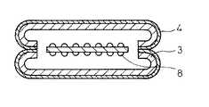
疎水性高分子の多孔質膜を用いた膜式加湿器が知られている。これは、図2に示すように、水の通過を阻止し、水蒸気の通過を許容する疎水性多孔質膜4に補強材3を積層したシートを用いて袋帯状の中空構造体を形成し、内部には水の流路を確保するためのスペーサー8を配置し、図3に示すように通風路を確保するためのセパレータ7と共に渦巻状に巻き上げ、取付枠5に収納したものである。この加湿器を運転するには、注水口6より加湿用の水を袋帯状の中空構造体の内部に供給し、取付枠5の開口部へと空気を送る。これにより、中空構造体の内部の水は、疎水性多孔質膜を介して水蒸気として外部へ放出され、加湿される。(例えば、特公平3−6109号公報)
ところが、このタイプの加湿器は、前記袋帯状の中空構造体の内部に給水されると、中空構造体が膨張して空気の通路を狭くするために、加湿効率が低下したり、空気の圧力損失を増大させる。また、内部水圧によるシートの破壊を防ぐために、補強材が不可欠であった。
【0003】
このため、特開昭61−180842号公報には、中空構造体の中空部を複数本の通路に分割し且つ給水量を制御するための制御部を設けることが提案されている。しかしながら、この方法は構造が複雑となり、コスト上からも実用的でない。
また、上記疎水性多孔質材料から成る加湿膜を用いた加湿器は、加湿用水に油性成分例えば配管工事等で用いられ切削油等が混入した場合、この油性成分が膜表面に付着した後膜内部に侵入し、加湿用水は、この侵入した部分から膜を通過し、漏れ出すようになる。また、長期間の使用により、加湿用水中に含まれる有機性、無機性の不純物がこの加湿膜の表面に付着し、この汚れにより加湿膜の撥水性が低下し、所定の耐水圧を維持出来なくなって加湿用水が漏れ出すようになる。このような加湿器からの水のリークは、加湿空気に水滴が混じり合い、室内を濡らすことになる。併せて、カルシウム等の成分を含んだ加湿用水が室内に飛散することとなり、飛散した水が乾燥すると、後に白粉が残り、白粉公害となる。
【0004】
このように、従来の加湿膜は耐切削油性、耐染色性等に欠けるため、このような加湿膜を用いた加湿器を運転する場合は、加湿用水を前処理し、これらの不純物を除去する必要があったが、この前処理は、設備的にも大がかりとなり、コスト高となり実用的ではなかった。従って、切削油による汚染、加湿用水中の不純物による汚染が発生すると、加湿膜の全面交換が必要であった。
【0005】
以上の様な問題を解決するために、特開平5−18572号公報には、多孔質疎水性高分子材料に親水性樹脂の連続被膜を設けた加湿膜を用いることが提案されている。しかしながら、この加湿膜は、多孔質材料を無孔質としたもので、透湿度の低下は避けられず、加湿能力の低下は、装置の大型化につながっていた。また、この加湿膜は無孔質である為に通気性が無く、加湿器内に加湿用水を導入する際、空気を排除する為の手段が別途必要であるという煩わしさがあった。
【0006】
【発明が解決しようとする課題】
本発明は、上記問題点を解決し、耐汚染性を有し、透湿度が高く、かつ給水後も空気の圧力損失が変化せず、補強材の不要な加湿用シート及びそのシートを用いた加湿ユニットを提供することを目的とする。
【0007】
【課題を解決するための手段】
本発明は、上記目的を達成するために、不織布、編布又は織布等の布帛からなる給水層の両面に、一体的に、疎水性多孔質膜からなる水蒸発層が設けられ、且つ、該疎水性多孔質膜が多孔質高分子基材の骨格を撥水性及び撥油性を有する有機ポリマで被覆して成る連続気孔を有する多孔質膜であることを特徴とする加湿用シート、及び端縁部が閉じられた請求項1,2又は3記載の加湿用シートが、通風のための間隔をおいて、略平行に、複数個設けられており、該複数個の加湿用シートの各々の間の適宜の位置に給水用板状体が挟まれて上下の加湿用シートと接合されており、該給水用板状棒には、複数個の加湿用シート及び給水用板状体を貫通する給水用小穴が設けられていることを特徴とする加湿ユニットを提供する。
【0008】
図1を参照すると、本発明の加湿用シートは給水層1の両面に疎水性多孔質膜2を積層したものである。
給水層1はこれに供給された加湿用水を保持するのに役立ち、この加湿用水は水蒸発層2を通して水蒸気としてシート外へ(外部へ)と放出される。
給水層1を構成する材料としては、アクリル樹脂、ジアセテート樹脂、ナイロン等から得られる不織布、編布、織布を用いることができるが、加湿器運転時の目詰まり防止等の観点から不織布、編布が特に好ましい。
【0009】
また、給水層1の厚さは任意の値をとることができるが、通常1〜10mm好ましくは2〜5mmである。また、目付けは不織布の場合、20〜1000g/m2、特に200〜300g/m2程度が好ましい。
水蒸発層2は、既述のとおり、給水層1の両面に一体的に積層され、給水層1に保持されている水を水蒸気として外部に放出する機能を有するものであり、疎水性多孔質膜からなる。
【0010】
本発明の疎水性多孔質膜2は、多孔質高分子基材の骨格を撥水性及び撥油性を有する有機ポリマで被覆して成る連続気孔を有する多孔質膜である。
この多孔質高分子基材は、基材の表面から裏面にかけて連通する多数の微細孔を有する高分子材料からなる。具体的には、耐熱性、耐腐食性を有するものが好ましく、ポリエチレン、ポリプロピレン等のポリオレフイン樹脂の多孔質体、ポリカーボネート、ポリスチレン、ポリ塩化ビニル、ポリ塩化ビニリデン、ポリエステル等の多孔質体、ポリテトラフルオロエチレン、テトラフルオロエチレン/ヘキサフルオロプロピレン共重合体、ポリフッ化ビニル、ポリフッ化ビニリデン等のフッ素樹脂の多孔質体等が使用出来るが、なかでもポリテトラフルオロエチレンを延伸処理して得られる多孔質材料は、フイブリルと呼ばれる小繊維とノードと呼ばれる結節から構成された独特の連通多孔質構造を有しており、本発明で用いる有機ポリマの微細粒子を安定してその構造体に取り込むことが出来、撥水性、耐熱性、耐薬品性にも優れており、好ましい材料といえる。
【0011】
多孔質高分子材料の孔径としては、本発明の有機ポリマの粒子が入れ込むことが必要であり、通常0.01〜10μm、特に0.1〜1μmの平均孔径のものが好ましい。この孔径が大きすぎると、耐水圧の低下をもたらし良くない。空孔率は、5〜95%、特に80〜95%のものが好ましい。空孔率が小さすぎると透湿度が小さくなって加湿効率が低下する。また大きすぎると多孔質材料の強度が低下する。厚みについては5〜1000μm、特に30〜100μmのものが好ましく、厚すぎると、透湿度が低下し、逆にあまり薄いものでは強度的に問題がある。
【0012】
本発明の多孔質高分子基材の骨格を被覆する有機ポリマは撥水性及び撥油性を有する有機ポリマであれば特に限定されないが、フッ素化有機側鎖を繰り返し表れるペンダント基として有するポリマが好適である。。この有機ポリマは、ポリマ鎖のペンダント基が高くフッ素化されているので、基材である多孔質高分子材料の撥水性および撥油性を増大させる働きがある。
【0013】
フッ素化有機側鎖を有する有機ポリマとしては、具体的には、式
【0014】
【化1】
(式中、nは3〜13の基数であり、RはH又はCH3である)のフルオロアルキルアクリレート及びフルオロアルキルメタクリレート、フルオロアルキルアリールウレタン、例えば
【0016】
【化2】
フルオロアルキルアリルウレタン、例えば
【0018】
【化3】
フルオロアルキルマレイン酸エステル、例えば
【0020】
【化4】
フルオロアルキルウレタンアクリレート、フルオロアルキルアミド、フルオロアルキルスルホアミドアクリレート、などのモノマを重合して得られるものが好適である。フッ素化アルキル部分は6〜16個の炭素原子を有することが好ましく、6〜12個の炭素原子を有することが最も好ましい。
撥水性及び撥油性を有するその他の有機ポリマとして主鎖に脂肪族環構造を有するものもある。具体的には、次の一般式で示されるものなどを挙げることができる。
【0022】
【化5】
(ただし、R1はFまたはCF3、R2はFまたはCF3)
【0024】
【化6】
(ただし、lは0〜5、mは0〜4、nは0〜1、1+m+nは1〜6、RはFまたはCF3)
【0026】
【化7】
(ただし、o,p,qは0〜5、o+p+qは1〜6)
これら一般式で示される含フッ素重合体の中でも、特に次のような環構造を有するものが好適に用いられる。
【0028】
【化8】
【化9】
市販されている「AFポリマ」(デュポン社の商品名)、「サイトップ」(旭硝子の商品名)なども使用可能である。
また、上記の如きポリマの撥水性及び撥油性を失なわない限り共重合体も使用できることはもちろんである。
ここで、共重合させる単量体としては、特に限定はされないが、フルオロオレフィン、フルオロビニルエーテルなどの含フッ素モノマが望ましく、例えば四フッ化エチレン、パーフルオロメチルビニルエーテル、パーフルオロプロピルビニルエーテル、あるいはカルボン酸基やスルホン酸基のような官能基を有するパーフルオロビニルエーテルなどが好適であり、さらにフッ化ビニリデン、フッ化ビニル、三フッ化塩化エチレンなども使用可能である。
【0031】
通常のフッ素化モノマの水性エマルジョン重合で得られる重合物の粒子は、0.1〜10μm程度の粒径となり、サブミクロンの多孔構造を持つ基材を均一に被覆することは困難であるが、本発明では、有機ポリマを平均粒径が0.01〜0.5μmの微細な粒子とすることにより、多孔質高分子材料の微細構造によく入り込み、この骨格組織に均一な厚みの被覆を形成するようにすることが出来る。
【0032】
このような微細なポリマ粒子を含む水性ラテックスは、モノマのマイクロエマルジョンを注意深く選択することにより可能にされた(PCT/US93/08884)。即ち、このモノママイクロエマルジョンは水、フルオロアルキル基を有する不飽和有機モノマ、フルオロ界面活性剤、及び任意に補助溶剤又は無機塩を混合して調製する。用いる量はフッ素化モノマ1〜40重量%、好ましくは5〜15重量%、界面活性剤1〜40重量%、好ましくは2〜25重量%、残部水である。
【0033】
ポリマ製造に際して別のモノマも存在し得るが、ペルフルオロアルキル基を有するモノマがモノマ合計量のうち少なくとも30重量%、好ましくは少なくとも50重量%を成すべきである。このような追加されるモノマには不飽和部分を含むエポキシ、カルボン酸、アミンなどある。
代表的なペルフルオロアルキル含有モノマは先に説明した。
【0034】
用いるフッ素化界面活性剤は一般式R1RYX(式中、R1は1〜15個、好ましくは6〜9個の炭素数のペルフルオロアルキル基又はペルフルオロアルキルエーテル基であり、Rは例えば炭素数0〜4のアルキレン基又はアルキレンチオエーテル(−CH2−S−CH2−)結合である。)を有する。フッ素化アニオン界面活性剤では、Yは例えばカルボキシル基(COO−)、スルホン基(SO3−)又はスルフェート基(SO4−)であり、Xはアルカリ金属イオン又はアンモニウムイオンである。フッ素化ノニオン界面活性剤ではYは例えばエトキシエチレン(OCH2CH2)m結合(式中、mは1〜15、好ましくは3〜9の整数)であり、Xは水酸基である。フッ素化カチオン界面活性剤ではYXは例えば第四級アンモニウム塩である。
【0035】
上記のマイクロエマルジョンを用いる単一バッチプロセスでポリママイクロエマルジョンを調製する場合、モノママイクロエマルジョンの温度を5〜100℃、好ましくは5〜80℃に調整し、フリーラジカル生成重合開始剤を添加する。好ましい開始剤にはペルスルフェート、アゾ系開始剤(例えば、2,2−アゾビス(2−アミドプロパン)ジヒドロクロリド)、過酸化物、光重合開始剤(例えば、紫外線重合開始剤、γ線重合開始剤)がある。開始剤の量はモノマ含分に対して0.01〜10重量%の範囲で変化できる。必要に応じて、補助溶剤、例えば、アルコール、アミンその他の両親媒性分子、又は塩を用いてマイクロエマルジョンの調製を促進することができる。
【0036】
重合開始剤を導入するとモノマの重合が開始し反応が進行する。得られるポリマ粒子ラテックスは0.01〜0.5μmの平均粒子径、10,000以上、好ましく20,000以上又は50,000以上のポリマ平均分子量を有する。異常に小さい粒径の粒子を含むポリマ系ではより大きい粒子のポリマ系と比べていくつかの利点がある。ポリマ系はコロイド分散体であり、通常濁りがなく透明である。小粒径粒子は均一な厚みの被覆を可能にし、多孔性基材の良好な透気性を維持する。ポリマ鎖のペンダント基が高くフッ素化されているので、ポリマを適用する基材の撥水性及び撥油性を増大する働きがある。
【0037】
このように製造したポリマは、水性ラテックス中のポリマ濃度を通常2〜25%、好ましくは5〜10%程度にし、基材をコロイド分散体中に浸漬し、又はコロイド分散体を基材にスプレーして、コロイド分散体から直接に適用できる。又、塗布装置(コータ)によって適用してもよい。
また、基材にモノママイクロエマルジョンを適用してから、マイクロエマルジョンの重合を光重合開始により行うことも可能である。
【0038】
基材に被覆を行った後、残っているすべての水、界面活性剤又は重合開始剤は加熱(例えば、150〜250℃)、水蒸気ストリッピング、真空蒸発など任意の便利な方法で除去することができる。
さらに、多孔性高分子基材の孔を形成する内部構造中に残った有機ポリマ粒子を溶融させることにより、多孔性基材の骨格を有機ポリマで被覆することができる。上記乾燥と溶融は同一処理で行うことも可能である。
【0039】
本発明では、この多孔質高分子基材の骨格を有機ポリマで被覆するとき、基材である多孔質高分子材料の連続した孔構造を維持するように調整する。従来の水性エマルジョン重合で得られるフッ素化ポリマでは、その粒子の大きさから、この孔構造を閉塞することになるが、上記したように、本発明で用いる有機ポリマは、平均粒径が0.01〜0.5μmの微細な粒子であるため、連続した孔構造の維持が可能であり、多孔質高分子材料の空孔率を著しく低下させることがない。そして、これにより、本発明の加湿用シートは、撥水性、耐汚染性を有するだけでなく、大きい透湿度を保持することができる。
【0040】
こうして製造される加湿用シートは、多孔質高分子基材、好適には延伸多孔質PTFEの骨格を撥水性かつ撥油性の有機ポリマで被覆しかつ連続気孔を維持しているので、疎水性高分子多孔膜に耐汚染性を付与しながらなおかつその透湿性を保持することが可能である。
なお、給水層の両面に積層される水蒸発層は、必ずしも同じ材料を用いる必要は無い。即ち、給水層の片面には無孔質透湿性樹脂からなる水蒸発層又は無孔質透湿性樹脂を多孔質高分子基材の少なくとも一面に含浸及び/又は積層して成る水蒸発層を設け、他の面には疎水性多孔質膜からなる水蒸発層を設けることもできる。ここで、多孔質高分子基材は前述のものと同様のものを用いることができる。また、無孔質透湿性樹脂は透湿性樹脂の連続被膜を形成するものであり、このようなものとしては、水酸基、カルボキシル基、スルホン酸基、アミノ基等の親水性基を持つ高分子であって、水膨潤性でかつ水不溶性のものが好ましく用いられる。例えば、少なくとも一部が架橋されたポリビニルアルコール、酢酸セルロース、硝酸セルロース等の親水性ポリマや、ポリアミノ酸、ポリウレタン、親水性含フッ素ポリマ、シリコーン樹脂等が使用可能であるが、耐熱性、耐薬品性、加工性、透湿度等を考慮に入れるとポリウレタン樹脂、フッ素系透湿性樹脂が好ましい。
【0041】
フッ素系透湿性樹脂としてはスルホン酸系パーフルオロイオン交換樹脂、特開平4−139237号に開示されている含フッ素モノマと親水基含有モノマとのコポリマなどの使用が望ましい。
無孔質透湿性樹脂層の厚さは、通常3〜400μm、好ましくは5〜30μmである。このものの厚さが厚すぎると水蒸気透過量の低下をもたらし、加湿能力が不十分となる。従って、無孔質透湿性樹脂で必要とされる機械的強度、耐用性を満足させる範囲で極力薄い方が好ましい。また、この無孔質透湿性樹脂の透湿度は、少なくとも10000g/m2・day 以上、好ましくは30000〜70000g/m2程度あった方がよい。
【0042】
給水層1と水蒸発層2との積層は、公知の方法で行うことが出来るが、例えば、給水層材料にグラビアパターンを施したロールでウレタン系接着剤を塗布し、その上に、疎水性多孔質膜を給水層に合わせてロール圧着する。この工程を給水層の上下面に連続して行う。この場合、接着剤を水蒸発層2面に塗布し、これを給水層1に圧着してもよい。なお、前記した有機ポリマの多孔質高分子基材の骨格への被覆工程は、給水層と水蒸気層との積層工程の後に行なってもよい。
【0043】
本発明の加湿用シートは、給水層と水蒸発層が一体的に積層された構造となっているため、従来の中空状の加湿器用膜材と比較して、強度的にも改善されたものとなっており、水蒸発層の外側に織布、不織布、編布等の補強材を積層して内部水圧によるシートの破壊を防ぐといった必要は無い。しかしながら、製造時等における水蒸発層の損傷を防止する意味でこれを設けることは一向に差し支えない。
【0044】
本発明の加湿用シートは、種々の形態で加湿器に用いることが出来る。その例を挙げると、先ず適宜の形状のシートの端縁部を接着剤による接着又は熱融着等の方法で閉鎖する。熱融着の場合、中間層材料の不織布等を溶かして行う。このシートを複数個準備し、通風の為の間隔をおいて、略平行に並べて加湿ユニットとする。この加湿ユニットに給水する為に、各シート間の適宜の位置に板状体を挟んで上下のシートと接合し、板状体及びシートを上下に貫通する給水用小穴を設ける。あるいは、貫通するように予めシートと板状体に穴をあけておき、これを接合するようにしてもよい。接合には接着剤を用いるとよい。このように構成すると、加湿用水は、この給水用小穴を経由して、各シートに供給され、毛細管現象により、シート全域に行き渡ることになる。他の給水方法としては、各シートにチューブ等を用いて給水口を設け、この給水口を経由して加湿用水を供給してもよい。
【0045】
他の例としては、本発明のシートを長尺に形成し、端縁部を閉鎖した後、スペーサを用いて一定の通風の為の間隔をあけて渦巻状に巻成したり、プリーツ状に折り畳んだりして加湿ユニットとすることも出来る。給水は、このシートに給水口を設けて行えばよい。
本発明の加湿ユニットは、必要に応じて加湿器用シートに排水口を設け、シート内に給水された加湿用水を洗浄の為に排出したり、あるいは、加湿器の運転中に排水口から一定の量の水を連続的に又は間欠的に排出して加湿用水の流れを作り、シート内の目詰まりを発生しにくくすることが出来る。
【0046】
この様にして形成された加湿ユニットは、取付枠に収納し、給水配管と接続し、送風手段により空気を送風することにより、空気を加湿することが出来る。
【0047】
【実施例】
以下の実施例において耐水圧、通気性及び透湿性を下記方法で測定した。
耐水圧
JIS L 1092 5.1項のB法に従った。また、切削油の耐圧試験もこれに準じた。
【0048】
通気性(ガーレー数)
JIS L 1096 6.27項のB法に準拠し、王研式透気度試験機により測定した。
透湿度
JIS L 1099中、4.2項のB法(酢酸カリウム法)により行なった。
【0049】
(水性ラテックス調製例1)
100ミリリットルのガラス製反応器にフルオロアクリレート即ち
【0050】
【化10】
(Du Pont製商品名Zonyl TA−N)10g、アンモニウムペルフルオロオクタノエート15g、蒸留水70gを入れ、攪拌しながら70℃に加熱した。淡緑色の清澄な(clear)マイクロエマルジョンが形成された。蒸留水5gに溶解した0.1gの過硫酸カリウムを反応器に入れて反応を開始させた。70℃で約1時間反応させた。それから反応混合物を室温まで冷却した。清澄なラテックスが得られ、室温で少なくとも24時間安定であった。ラテックスの平均粒径を測定すると擬弾性光散乱法で約0.03μmであった。得られたポリマの重量平均分子量を測定すると古典光散乱法で約1,000,000以上であった。
【0052】
(水性ラテックス調製例2)
100ミリリットルのガラス製反応器にフルオロメタリレート(Dupont製商品名Zonyl TM)10g、アンモニウムペルフルオロオクタノエート20g、蒸留水65gを入れ、撹拌しながら75℃に加熱した。淡緑色の清澄マイクロエマルジョンが形成された。次に5gの蒸留水に溶解した0.1gの過硫酸アンモニウムを反応器に入れて反応を開始した。75℃で約1時間重合させてから反応混合物を室温まで冷却した。清澄ラテックスが得られ、室温で少なくとも24時間安定であった。ラテックスの平均粒径を擬弾性光散乱法で測定すると約0.03μmであった。重量平均分子量を古典光散乱法で測定すると1,000,000以上であった。
【0053】
(水性ラテックス調製例3)
フッ素化モノマ、水素化モノマ、フッ素化界面活性剤、及び水素化界面活性剤の混合物を用いた。
100ミリリットルのガラス製反応器にフルオロアクリレート即ち(Du Pont製商品名Zonyl TA−N)4g、スチレン(Aldrich Chemical製)2g、アンモニウムペルフルオロオクタノエート3g、ナトリウムドデシルスルフェート(Aldrich製)7g、蒸留水80gを入れ、攪拌しながら70℃に加熱した。清澄マイクロエマルジョンが形成された。蒸留水5gに溶解した0.07gのカチオン重合開始剤(Wako製、V−50)を反応器に入れて反応を開始させた。70℃で約2時間重合させた。それから反応混合物を室温まで冷却した。清澄なラテックスが得られ、室温で少なくとも24時間安定であった。
【0054】
(疎水性多孔質膜調製例)
PTFE多孔質膜(厚さ50μm、空孔率80%、平均孔径0.2μm、ガーレー数10秒)を水性ラテックス調製例1で調製した水性ラテックスを蒸留水で3倍に希釈したものに浸漬し、余剰液体を滴下除去し、225℃のオーブン中に3分間置いた。この処理で水とフッ素化界面活性剤が除去されると共に、フッ素化ポリマが溶融し流動した。得られた膜のガーレー数を測定すると11秒であり、連続気孔が維持していることが確認された。
【0055】
この処理膜の耐切削油性を上水道管用切削油(ミヤガワ50W)を用いた耐圧試験で評価した。また、同じく上記処理膜でたて10cm×よこ10cmの袋を作成し、袋中に水道水を連続的に供給しながら、60℃乾燥熱風を吹付け、袋内部の水を、膜を介して250cc/cm2の量(50l)蒸発させた後、水中含有物が堆積した部分の膜の耐水性試験を実施した。
【0056】
比較のために、上記有機ポリマ被覆処理を行なわない上記と同じPTFE多孔質膜について、上記と同じ評価試験を行なった。
結果を下記表に示す。
疎水性多孔質膜調製例で作製したフッ素化有機ポリマ処理PTFE膜の片面に、グラビアパターンロール(開孔率70%に設定)を用いて接着剤(ウレタン樹脂)を塗布し、この面にアクリルの不織布(厚さ3mm、目付50g/m)を合わせ、圧力3kg/cm2、速度5m/分の条件でロール圧着を行った。その後、アクリル不織布の他の面にも同じ方法、条件で、同じ有機ポリマ処理PTFE膜を圧着した。この様に連続して3層一体構造とした加湿器用シートの透湿度は50,000g/m2・24hrであった。
【0057】
この様にして作った幅46mm、長さ15mの加湿用シートの巾方向両端及び長さ方向両端を加熱加圧によりシールし、端末に注水チューブを付けた構造とした。
この加湿用シートを幅46mm、長さ15mの波板状スペーサ(高さ2.5mm、ピッチ6.2mm)を共に図3に示したと同じように組付け、40℃で湿度15%の空気を風速2m/sec で吹付けた時、加湿量は1kg/hr確保できた。この時風の圧力損失は5μmH2Oで安定していた。さらにこの加湿器に0.1%切削油を流し込みリークを確認したがリークは発生しなかった。
【0058】
(加湿ユニットの調製例)
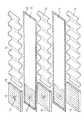
図4を参照すると、加湿用シートの調製例の如く調製した加湿用シート11は、幅46mm、長さ990mm、厚さ2.0mmで、その周縁部12がシールされている。また、一端部近くに直径6mmの注水口13が設けられている。このような加湿用シート25枚と、幅45mm、長さ945mm、ピッチ6.2mm、高さ2.5mmのポリエチレン製波板14の26枚、及び幅46mm、長さ46mm、厚さ3.0mmの塩化ビニル樹脂板15の26枚とを積層し、図4中の斜線部16に塩化ビニル系接着剤を塗布して接着した。樹脂板15にも注水口13を設けている。従って、注水口は最上段の樹脂板15から最下段の加湿用シート11までの貫通口を形成し、最下段の樹脂板15で閉鎖されている。
【0059】
図5にこうして積層した加湿用シート20を示す。
図6は、この積層品を取付枠(外寸1000mm×150mm×50mmの溶融亜鉛メッキ鋼板製)21中に収容し、かつチューブコネクター(外径8mm、内径6mm)22を取付け、加湿ユニットを完成した。
完成した加湿ユニットに上水を供給し、45℃で湿度20%の空気を風速1.5m/sec で送風して試験した。このとき加湿能力として1.5リットル/時が記録された。空気の圧力損失は7Pa以下であった。
【0060】
図7に供給水を加熱した場合の加湿量を調べた結果を示す。
【0061】
【発明の効果】
本発明の加湿用シート又は加湿ユニットは、給水層と水蒸発層とを一体構造とすることにより入水時の膜の膨れはなくなり、空気の圧力損失は安定ないし減少する。
また、特定の加湿膜を使用することにより切削油等の油性成分や、加湿用水中の有機性・無機性の不純物に対して耐汚染性を有し、白粉公害の発生しないクリーンな加湿空気を供給する膜式加湿器が得られる。
【0062】
さらに、本発明の加湿用シートはその構造が連続多孔質構造を維持していることから加湿器運転時に於ける加湿用水の導入も容易であり、加湿能力も優れたものである。
【図面の簡単な説明】
【図1】本発明の加湿用シートの断面図。
【図2】従来の加湿用シートの説明図。
【図3】従来の加湿ユニットの概略斜視図。
【図4】本発明の加湿ユニット用の加湿用シートを積層する様子を示す。
【図5】図4の積層品を示す。
【図6】本発明の加湿ユニットの例を示す。
【図7】供給水を加熱した場合の加湿量を示す。
【符号の説明】
1…給水層
2…水蒸発層
3…補強材
4…疎水性多孔質膜
5…取付け枠
6…注水口
7…セパレーター
8…水流路確保用スペーサー
9…袋状加湿器用膜材
11…加湿用シート
13…注水口
14…スペーサ
15…樹脂板
21…取付枠[0001]
[Industrial application fields]
The present invention relates to a humidifying sheet using a moisture permeable membrane and a humidifying unit using the same.
[0002]
[Prior art]
A membrane humidifier using a porous membrane of a hydrophobic polymer is known. As shown in FIG. 2, a bag belt-like hollow structure is formed by using a sheet in which the reinforcing
However, when this type of humidifier is supplied with water into the bag-shaped hollow structure, the hollow structure expands and narrows the air passage. Increase loss. In addition, a reinforcing material was indispensable in order to prevent the sheet from being destroyed by internal water pressure.
[0003]
For this reason, Japanese Patent Laid-Open No. 61-180842 proposes to provide a control unit for dividing the hollow portion of the hollow structure into a plurality of passages and controlling the amount of water supply. However, this method has a complicated structure and is not practical from the viewpoint of cost.
In addition, the humidifier using the humidifying membrane made of the hydrophobic porous material described above is a film after the oil component adheres to the membrane surface when the oil component such as cutting oil is mixed in the humidifying water. Intruding into the interior, the humidifying water passes through the membrane from the intruding portion and leaks out. In addition, with long-term use, organic and inorganic impurities contained in the water for humidification adhere to the surface of the humidifying film, and this dirt reduces the water repellency of the humidifying film and maintains a predetermined water pressure resistance The humidifying water leaks out. Such a leak of water from the humidifier mixes water droplets with the humidified air and wets the room. At the same time, the humidifying water containing components such as calcium is scattered indoors, and when the scattered water is dried, white powder remains later and white powder pollution occurs.
[0004]
Thus, since the conventional humidifying film lacks cutting oil resistance, dyeing resistance, etc., when operating a humidifier using such a humidifying film, pretreat the humidifying water and remove these impurities. Although it was necessary, this pretreatment was not practical because of the large equipment and high cost. Therefore, when contamination with cutting oil or contamination with water in the humidifying water occurs, it is necessary to replace the entire humidification film.
[0005]
In order to solve the above problems, Japanese Patent Application Laid-Open No. 5-18572 proposes to use a humidified film in which a continuous film of a hydrophilic resin is provided on a porous hydrophobic polymer material. However, this humidified membrane is made of a porous material made of non-porous material, and a decrease in moisture permeability is inevitable, and a decrease in humidification capacity has led to an increase in the size of the apparatus. Further, since this humidifying membrane is nonporous, it has no air permeability, and there is a trouble that a means for excluding air is necessary when introducing humidifying water into the humidifier.
[0006]
[Problems to be solved by the invention]
The present invention solves the above-mentioned problems, uses a humidifying sheet that does not require a reinforcing material, and has a sheet that has contamination resistance, has high moisture permeability, and does not change air pressure loss even after water supply. An object is to provide a humidifying unit.
[0007]
[Means for Solving the Problems]
In order to achieve the above object, the present invention is provided with a water evaporation layer made of a hydrophobic porous membrane integrally on both surfaces of a water supply layer made of a fabric such as a nonwoven fabric, a knitted fabric or a woven fabric, and The humidifying sheet, wherein the hydrophobic porous membrane is a porous membrane having continuous pores formed by coating a skeleton of a porous polymer base material with an organic polymer having water and oil repellency, and an end The humidifying sheet according to
[0008]
Referring to FIG. 1, the humidifying sheet of the present invention is obtained by laminating a hydrophobic
The
As a material constituting the
[0009]
Moreover, although the thickness of the
As described above, the
[0010]
The hydrophobic
This porous polymer substrate is made of a polymer material having a large number of micropores communicating from the front surface to the back surface of the substrate. Specifically, those having heat resistance and corrosion resistance are preferred, porous bodies of polyolefin resins such as polyethylene and polypropylene, porous bodies such as polycarbonate, polystyrene, polyvinyl chloride, polyvinylidene chloride, polyester, and polytetra Fluororesin porous bodies such as fluoroethylene, tetrafluoroethylene / hexafluoropropylene copolymer, polyvinyl fluoride, and polyvinylidene fluoride can be used. Among them, porous obtained by stretching polytetrafluoroethylene The material has a unique continuous porous structure composed of fibrils called fibrils and nodules called nodes, and can stably incorporate fine particles of the organic polymer used in the present invention into the structure. Excellent material for water repellency, heat resistance and chemical resistance. It can be said that.
[0011]
As the pore diameter of the porous polymer material, it is necessary that the organic polymer particles of the present invention be inserted, and those having an average pore diameter of usually 0.01 to 10 μm, particularly 0.1 to 1 μm are preferable. If the pore diameter is too large, the water pressure resistance is lowered, which is not good. The porosity is preferably 5 to 95%, particularly preferably 80 to 95%. If the porosity is too small, the moisture permeability becomes small and the humidification efficiency decreases. If it is too large, the strength of the porous material is lowered. The thickness is preferably 5 to 1000 μm, particularly 30 to 100 μm, and if it is too thick, the water vapor transmission rate is lowered.
[0012]
The organic polymer that coats the skeleton of the porous polymer substrate of the present invention is not particularly limited as long as it is an organic polymer having water repellency and oil repellency, but a polymer having pendant groups that repeatedly represent fluorinated organic side chains is suitable. is there. . This organic polymer has a function of increasing the water repellency and oil repellency of the porous polymer material as a base material because the pendant group of the polymer chain is highly fluorinated.
[0013]
Specific examples of organic polymers having fluorinated organic side chains include:
[0014]
[Chemical 1]
(Wherein n is a radix of 3 to 13 and R is H or CH3Fluoroalkyl acrylates and fluoroalkyl methacrylates, fluoroalkylaryl urethanes such as
[0016]
[Chemical 2]
Fluoroalkylallylurethane, such as
[0018]
[Chemical 3]
Fluoroalkyl maleates such as
[0020]
[Formula 4]
Those obtained by polymerizing monomers such as fluoroalkylurethane acrylate, fluoroalkylamide, and fluoroalkylsulfoamide acrylate are preferred. The fluorinated alkyl moiety preferably has 6 to 16 carbon atoms, and most preferably has 6 to 12 carbon atoms.
Some other organic polymers having water repellency and oil repellency have an aliphatic ring structure in the main chain. Specific examples include those represented by the following general formula.
[0022]
[Chemical formula 5]
(However, R1Is F or CF3, R2Is F or CF3)
[0024]
[Chemical 6]
(Where l is 0 to 5, m is 0 to 4, n is 0 to 1, 1 + m + n is 1 to 6, R is F or CF3)
[0026]
[Chemical 7]
(However, o, p, q are 0-5, o + p + q is 1-6)
Among these fluorine-containing polymers represented by the general formula, those having the following ring structure are preferably used.
[0028]
[Chemical 8]
[Chemical 9]
Commercially available “AF polymer” (trade name of DuPont), “Cytop” (trade name of Asahi Glass) and the like can also be used.
Of course, a copolymer can be used as long as the water repellency and oil repellency of the polymer are not lost.
Here, the monomer to be copolymerized is not particularly limited, but is preferably a fluorine-containing monomer such as fluoroolefin and fluorovinyl ether, such as tetrafluoroethylene, perfluoromethyl vinyl ether, perfluoropropyl vinyl ether, or carboxylic acid. Perfluorovinyl ether having a functional group such as a sulfonic acid group or a sulfonic acid group is preferable, and vinylidene fluoride, vinyl fluoride, ethylene trifluoride chloride, or the like can also be used.
[0031]
Polymer particles obtained by normal aqueous emulsion polymerization of a fluorinated monomer have a particle size of about 0.1 to 10 μm, and it is difficult to uniformly coat a substrate having a submicron porous structure. In the present invention, the organic polymer is made into fine particles having an average particle diameter of 0.01 to 0.5 μm, so that the fine structure of the porous polymer material is well entered and a uniform thickness coating is formed on this skeletal structure. You can do that.
[0032]
Aqueous latexes containing such fine polymer particles have been made possible by careful selection of monomer microemulsions (PCT / US93 / 08884). That is, the monomer microemulsion is prepared by mixing water, an unsaturated organic monomer having a fluoroalkyl group, a fluorosurfactant, and optionally a co-solvent or an inorganic salt. The amount used is 1 to 40% by weight of fluorinated monomer, preferably 5 to 15% by weight, 1 to 40% by weight of surfactant, preferably 2 to 25% by weight and the balance water.
[0033]
While other monomers may be present in the production of the polymer, the monomer having perfluoroalkyl groups should constitute at least 30% by weight of the total amount of monomers, preferably at least 50% by weight. Such added monomers include epoxies, carboxylic acids, amines, etc. containing unsaturated moieties.
Representative perfluoroalkyl-containing monomers are described above.
[0034]
The fluorinated surfactant used is of the general formula R1RYX (wherein R1Is a perfluoroalkyl group or perfluoroalkyl ether group having 1 to 15 carbon atoms, preferably 6 to 9 carbon atoms, and R is, for example, an alkylene group or alkylene thioether (—
[0035]
When preparing a polymer microemulsion in a single batch process using the above microemulsion, the temperature of the monomer microemulsion is adjusted to 5 to 100 ° C., preferably 5 to 80 ° C., and a free radical generating polymerization initiator is added. Preferred initiators include persulfate, azo initiators (for example, 2,2-azobis (2-amidopropane) dihydrochloride), peroxides, photopolymerization initiators (for example, ultraviolet polymerization initiators, gamma ray polymerization). Initiator). The amount of initiator can vary from 0.01 to 10% by weight relative to the monomer content. If necessary, co-solvents such as alcohols, amines or other amphiphilic molecules, or salts can be used to facilitate the preparation of the microemulsion.
[0036]
When a polymerization initiator is introduced, polymerization of the monomer starts and the reaction proceeds. The resulting polymer particle latex has an average particle size of 0.01 to 0.5 μm, a molecular average molecular weight of 10,000 or more, preferably 20,000 or more, or 50,000 or more. Polymer systems containing unusually small particle sizes have several advantages over larger particle polymer systems. The polymer system is a colloidal dispersion and is usually transparent without turbidity. Small particle size particles allow for uniform thickness coverage and maintain good air permeability of the porous substrate. Since the pendant group of the polymer chain is highly fluorinated, it serves to increase the water and oil repellency of the substrate to which the polymer is applied.
[0037]
The polymer thus produced has a polymer concentration in the aqueous latex of usually 2 to 25%, preferably about 5 to 10%, and the substrate is immersed in the colloidal dispersion, or the colloidal dispersion is sprayed on the substrate. And can be applied directly from a colloidal dispersion. Moreover, you may apply with a coating device (coater).
It is also possible to polymerize the microemulsion by starting photopolymerization after applying the monomer microemulsion to the substrate.
[0038]
After coating the substrate, any remaining water, surfactant or polymerization initiator should be removed by any convenient method such as heating (eg 150-250 ° C.), steam stripping, vacuum evaporation, etc. Can do.
Furthermore, the skeleton of the porous substrate can be coated with the organic polymer by melting the organic polymer particles remaining in the internal structure forming the pores of the porous polymer substrate. The drying and melting can be performed in the same process.
[0039]
In the present invention, when the skeleton of the porous polymer substrate is coated with an organic polymer, the porous polymer material is adjusted so as to maintain a continuous pore structure of the porous polymer material. In the fluorinated polymer obtained by the conventional aqueous emulsion polymerization, the pore structure is blocked due to the size of the particle. As described above, the organic polymer used in the present invention has an average particle size of 0.00. Since the particles are fine particles of 01 to 0.5 μm, it is possible to maintain a continuous pore structure, and the porosity of the porous polymer material is not significantly reduced. As a result, the humidifying sheet of the present invention not only has water repellency and stain resistance, but also can maintain high moisture permeability.
[0040]
The humidifying sheet thus produced has a porous polymer base material, preferably a stretched porous PTFE skeleton coated with a water- and oil-repellent organic polymer and maintains continuous pores. It is possible to retain the moisture permeability while imparting stain resistance to the molecular porous membrane.
In addition, it is not necessary to use the same material for the water evaporation layer laminated | stacked on both surfaces of a water supply layer. That is, a water evaporation layer composed of a nonporous moisture-permeable resin or a water evaporation layer formed by impregnating and / or laminating at least one surface of a porous polymer substrate with a nonporous moisture-permeable resin is provided on one side of the water supply layer. Also, a water evaporation layer made of a hydrophobic porous membrane can be provided on the other surface. Here, the same porous polymer substrate as described above can be used. Non-porous moisture-permeable resin forms a continuous film of moisture-permeable resin, such as a polymer having a hydrophilic group such as a hydroxyl group, a carboxyl group, a sulfonic acid group, and an amino group. In addition, water-swellable and water-insoluble ones are preferably used. For example, hydrophilic polymers such as polyvinyl alcohol, cellulose acetate, and cellulose nitrate that are at least partially crosslinked, polyamino acids, polyurethanes, hydrophilic fluorine-containing polymers, silicone resins, etc. can be used. In view of properties, workability, moisture permeability, etc., polyurethane resins and fluorine-based moisture permeable resins are preferable.
[0041]
As the fluorine-based moisture-permeable resin, it is desirable to use a sulfonic acid-based perfluoro ion exchange resin, a copolymer of a fluorine-containing monomer and a hydrophilic group-containing monomer disclosed in JP-A-4-139237.
The thickness of the nonporous moisture-permeable resin layer is usually 3 to 400 μm, preferably 5 to 30 μm. If this is too thick, it will cause a decrease in the amount of water vapor permeated and the humidification capacity will be insufficient. Therefore, it is preferable that the thickness is as thin as possible as long as the mechanical strength and durability required for the nonporous moisture-permeable resin are satisfied. Further, the moisture permeability of the nonporous moisture-permeable resin is at least 10,000 g / m.2-Day or more, preferably 30000-70000 g / m2It is better to have a degree.
[0042]
Lamination of the
[0043]
The humidifying sheet of the present invention has a structure in which a water supply layer and a water evaporation layer are integrally laminated, so that it is improved in strength compared to a conventional hollow humidifier membrane material. Thus, there is no need to laminate a reinforcing material such as a woven fabric, a nonwoven fabric, or a knitted fabric on the outside of the water evaporation layer to prevent the sheet from being destroyed by internal water pressure. However, this may be provided in a way that prevents damage to the water evaporation layer during production or the like.
[0044]
The humidifying sheet of the present invention can be used in a humidifier in various forms. For example, first, the edge of an appropriately shaped sheet is closed by a method such as bonding with an adhesive or heat sealing. In the case of heat fusion, the nonwoven fabric of the intermediate layer material is melted. A plurality of these sheets are prepared, and are arranged substantially in parallel at intervals for ventilation to form a humidifying unit. In order to supply water to this humidifying unit, a plate-like body is sandwiched between upper and lower sheets at appropriate positions between the sheets, and a small hole for water supply is provided through the plate-like body and the sheet. Alternatively, a hole may be made in advance in the sheet and the plate-like body so as to penetrate, and this may be joined. An adhesive may be used for bonding. If comprised in this way, the water for humidification will be supplied to each sheet | seat via this small hole for water supply, and will spread throughout the sheet | seat by a capillary phenomenon. As another water supply method, each sheet may be provided with a water supply port using a tube or the like, and humidification water may be supplied via the water supply port.
[0045]
As another example, after forming the sheet of the present invention into a long shape and closing the edge portion, it is wound in a spiral shape with a space for a constant ventilation using a spacer, or in a pleated shape. It can be folded into a humidification unit. Water supply may be performed by providing a water supply opening on this sheet.
The humidification unit of the present invention is provided with a drain outlet in the humidifier sheet as necessary, and discharges the humidifying water supplied in the sheet for cleaning, or is fixed from the drain outlet during operation of the humidifier. A quantity of water can be discharged continuously or intermittently to create a flow of water for humidification, and clogging in the sheet is less likely to occur.
[0046]
The humidification unit thus formed can be humidified by being housed in a mounting frame, connected to a water supply pipe, and blowing air by a blowing means.
[0047]
【Example】
In the following examples, water pressure resistance, air permeability and moisture permeability were measured by the following methods.
Water pressure resistance
The method B of JIS L 1092 5.1 was followed. Moreover, the pressure resistance test of the cutting oil was based on this.
[0048]
Breathability (Gurley number)
In accordance with method B of JIS L 1096, paragraph 6.27, the measurement was performed with a Oken air permeability tester.
Moisture permeability
This was carried out by the method B (potassium acetate method) described in 4.2 in JIS L 1099.
[0049]
(Aqueous latex preparation example 1)
In a 100 ml glass reactor, fluoroacrylate,
[0050]
[Chemical Formula 10]
(Product name Zonyl TA-N manufactured by Du Pont) 10 g, 15 g of ammonium perfluorooctanoate, and 70 g of distilled water were added and heated to 70 ° C. with stirring. A pale green clear microemulsion was formed. 0.1 g of potassium persulfate dissolved in 5 g of distilled water was placed in the reactor to initiate the reaction. The reaction was carried out at 70 ° C. for about 1 hour. The reaction mixture was then cooled to room temperature. A clear latex was obtained and was stable for at least 24 hours at room temperature. The average particle size of the latex was measured and found to be about 0.03 μm by the pseudoelastic light scattering method. When the weight average molecular weight of the obtained polymer was measured, it was about 1,000,000 or more by the classical light scattering method.
[0052]
(Aqueous latex preparation example 2)
A 100 ml glass reactor was charged with 10 g of fluorometallate (trade name Zonyl ™ manufactured by Dupont), 20 g of ammonium perfluorooctanoate and 65 g of distilled water, and heated to 75 ° C. with stirring. A pale green clear microemulsion was formed. Next, 0.1 g of ammonium persulfate dissolved in 5 g of distilled water was placed in the reactor to initiate the reaction. After polymerization at 75 ° C. for about 1 hour, the reaction mixture was cooled to room temperature. A clear latex was obtained and was stable for at least 24 hours at room temperature. When the average particle size of the latex was measured by the pseudoelastic light scattering method, it was about 0.03 μm. When the weight average molecular weight was measured by the classical light scattering method, it was 1,000,000 or more.
[0053]
(Aqueous latex preparation example 3)
A mixture of fluorinated monomer, hydrogenated monomer, fluorinated surfactant, and hydrogenated surfactant was used.
In 100 ml glass reactor, 4 g of fluoroacrylate (trade name Zonyl TA-N manufactured by Du Pont), 2 g of styrene (manufactured by Aldrich Chemical), 3 g of ammonium perfluorooctanoate, 7 g of sodium dodecyl sulfate (manufactured by Aldrich), distillation 80 g of water was added and heated to 70 ° C. with stirring. A clear microemulsion was formed. 0.07 g of cationic polymerization initiator (manufactured by Wako, V-50) dissolved in 5 g of distilled water was placed in the reactor to initiate the reaction. Polymerization was carried out at 70 ° C. for about 2 hours. The reaction mixture was then cooled to room temperature. A clear latex was obtained and was stable for at least 24 hours at room temperature.
[0054]
(Preparation example of hydrophobic porous membrane)
A PTFE porous membrane (
[0055]
The cutting oil resistance of the treated film was evaluated by a pressure test using a water cutting pipe cutting oil (Miyagawa 50W). Similarly, a bag of 10 cm x 10 cm is prepared with the above treated membrane, and hot water is blown at 60 ° C. while continuously supplying tap water into the bag, and the water inside the bag is passed through the membrane. 250cc / cm2After evaporating the amount (50 l) of water, a water resistance test was carried out on the film where the water content was deposited.
[0056]
For comparison, the same evaluation test as described above was performed for the same PTFE porous membrane as described above that was not subjected to the organic polymer coating treatment.
The results are shown in the table below.
An adhesive (urethane resin) is applied to one side of the fluorinated organic polymer-treated PTFE membrane prepared in the hydrophobic porous membrane preparation example using a gravure pattern roll (set to a porosity of 70%), and acrylic on this side. Of non-woven fabric (
[0057]
The both sides in the width direction and both ends in the length direction of the humidifying sheet having a width of 46 mm and a length of 15 m thus produced were sealed by heating and pressing, and a water injection tube was attached to the terminal.
This humidifying sheet was assembled in the same way as shown in FIG. 3 with corrugated spacers (height 2.5 mm, pitch 6.2 mm) having a width of 46 mm and a length of 15 m, and air with a humidity of 15% at 40 ° C. When sprayed at a wind speed of 2 m / sec, a humidification amount of 1 kg / hr could be secured. At this time, the pressure loss of the wind is 5μmH2It was stable at O. Further, 0.1% cutting oil was poured into the humidifier to confirm the leak, but no leak occurred.
[0058]
(Preparation example of humidification unit)
Referring to FIG. 4, the
[0059]
FIG. 5 shows the
FIG. 6 shows that this laminated product is accommodated in a mounting frame (made of hot dip galvanized steel plate with outer dimensions of 1000 mm × 150 mm × 50 mm) 21 and a tube connector (outer diameter 8 mm,
Water was supplied to the completed humidification unit, and air at a humidity of 20% at 45 ° C. was blown at a wind speed of 1.5 m / sec for testing. At this time, 1.5 liters / hour was recorded as the humidifying capacity. The pressure loss of air was 7 Pa or less.
[0060]
FIG. 7 shows the results of examining the amount of humidification when the feed water is heated.
[0061]
【The invention's effect】
In the humidifying sheet or humidifying unit of the present invention, the water supply layer and the water evaporation layer are integrated, so that the membrane does not swell when entering water, and the pressure loss of air is stabilized or reduced.
In addition, by using a specific humidifying film, clean humid air that has contamination resistance against oily components such as cutting oil and organic and inorganic impurities in the water for humidification, and does not cause white powder pollution. A supplied membrane humidifier is obtained.
[0062]
Furthermore, since the structure of the humidifying sheet of the present invention maintains a continuous porous structure, it is easy to introduce humidifying water during operation of the humidifier, and the humidifying ability is excellent.
[Brief description of the drawings]
FIG. 1 is a cross-sectional view of a humidifying sheet according to the present invention.
FIG. 2 is an explanatory view of a conventional humidifying sheet.
FIG. 3 is a schematic perspective view of a conventional humidification unit.
FIG. 4 shows how the humidifying sheets for the humidifying unit of the present invention are stacked.
FIG. 5 shows the laminate of FIG.
FIG. 6 shows an example of a humidifying unit of the present invention.
FIG. 7 shows the amount of humidification when the feed water is heated.
[Explanation of symbols]
1 ... Water supply layer
2 ... Water evaporation layer
3 ... Reinforcing material
4 ... Hydrophobic porous membrane
5 ... Mounting frame
6 ... Water inlet
7 ... Separator
8 ... Spacer spacer
9 ... Membrane material for bag-type humidifier
11 ... Humidifying sheet
13 ... Water inlet
14 ... Spacer
15 ... Resin plate
21 ... Mounting frame
Claims (4)
Translated fromJapanesePriority Applications (2)
| Application Number | Priority Date | Filing Date | Title |
|---|---|---|---|
| JP24798594AJP3606614B2 (en) | 1994-10-13 | 1994-10-13 | Humidification sheet and humidification unit |
| EP95307261AEP0707179A3 (en) | 1994-10-13 | 1995-10-12 | Humidifier assembly |
Applications Claiming Priority (1)
| Application Number | Priority Date | Filing Date | Title |
|---|---|---|---|
| JP24798594AJP3606614B2 (en) | 1994-10-13 | 1994-10-13 | Humidification sheet and humidification unit |
Publications (2)
| Publication Number | Publication Date |
|---|---|
| JPH08110071A JPH08110071A (en) | 1996-04-30 |
| JP3606614B2true JP3606614B2 (en) | 2005-01-05 |
Family
ID=17171486
Family Applications (1)
| Application Number | Title | Priority Date | Filing Date |
|---|---|---|---|
| JP24798594AExpired - LifetimeJP3606614B2 (en) | 1994-10-13 | 1994-10-13 | Humidification sheet and humidification unit |
Country Status (2)
| Country | Link |
|---|---|
| EP (1) | EP0707179A3 (en) |
| JP (1) | JP3606614B2 (en) |
Families Citing this family (17)
| Publication number | Priority date | Publication date | Assignee | Title |
|---|---|---|---|---|
| DE19910441C1 (en) | 1999-03-10 | 2000-06-21 | Fraunhofer Ges Forschung | Air humidifier comprises membrane contactor which has at least one tube membrane embedded in hydrophile porous body of ceramic, polymer or fabric preferably of porous thread material with hydrophilic surface |
| JP3275608B2 (en)* | 1995-02-17 | 2002-04-15 | 三菱電機株式会社 | Humidifier |
| JP2969075B2 (en)* | 1996-02-26 | 1999-11-02 | ジャパンゴアテックス株式会社 | Degassing device |
| US5888275A (en)* | 1996-02-26 | 1999-03-30 | Japan Gore-Tex, Inc. | Assembly for deaeration of liquids |
| DE19640866A1 (en)* | 1996-10-04 | 1998-04-09 | Daramic Inc | Air cooling device |
| DE19730245B4 (en) | 1997-07-15 | 2007-08-30 | W.L. Gore & Associates Gmbh | Coating material, coated material and method of making the same |
| DE20000528U1 (en)* | 2000-01-13 | 2001-06-07 | Melitta Haushaltsprodukte GmbH & Co. KG, 32427 Minden | Evaporator block |
| GB0710773D0 (en)* | 2007-06-05 | 2007-07-18 | British American Tobacco Co | Humidifying capsule for use with tobacco products |
| GB0710784D0 (en)* | 2007-06-05 | 2007-07-18 | British American Tobacco Co | Controlled moisture release humidifier for use with tobacco products |
| US8735306B2 (en) | 2008-02-29 | 2014-05-27 | Bha Altair, Llc | Oleophobic laminated article |
| US7825046B2 (en)* | 2008-02-29 | 2010-11-02 | General Electric Company | Oleophobic laminated article |
| US20100024651A1 (en) | 2008-07-30 | 2010-02-04 | General Electric Company | Membrane contactor systems for gas-liquid contact |
| US10208168B2 (en) | 2011-10-25 | 2019-02-19 | Kraton Polymers U.S. Llc | Polyoxyalkyleneamine modified sulfonated block copolymers, their preparation and their use |
| US11713877B2 (en) | 2018-05-04 | 2023-08-01 | Donaldson Company, Inc. | Systems and methods for removing organic compounds from steam |
| US11649178B2 (en) | 2019-10-15 | 2023-05-16 | Donaldson Company, Inc. | Systems and methods for removing organic compounds from water used to generate steam |
| CN112451826A (en)* | 2020-07-30 | 2021-03-09 | 北京万生人和科技有限公司 | Oxygen humidifying pipeline |
| CN117327310B (en)* | 2023-10-07 | 2024-09-24 | 深圳市富程威科技股份有限公司 | Polytetrafluoroethylene super-hydrophobic breathable film and preparation method and application thereof |
Family Cites Families (20)
| Publication number | Priority date | Publication date | Assignee | Title |
|---|---|---|---|---|
| CA962021A (en) | 1970-05-21 | 1975-02-04 | Robert W. Gore | Porous products and process therefor |
| JPS61180842A (en)* | 1985-01-31 | 1986-08-13 | Mitsubishi Electric Corp | humidifier |
| JPS61240045A (en)* | 1985-04-15 | 1986-10-25 | Mitsubishi Electric Corp | Humidifier membrane module |
| JPS61250429A (en)* | 1985-04-25 | 1986-11-07 | Mitsubishi Electric Corp | Humidifier |
| JPH01196436A (en)* | 1988-01-29 | 1989-08-08 | Matsushita Electric Ind Co Ltd | Humidification device |
| JP2678042B2 (en)* | 1989-01-20 | 1997-11-17 | 松下冷機株式会社 | humidifier |
| AU633316B2 (en)* | 1989-04-28 | 1993-01-28 | Asahi Glass Company Limited | Water and oil repellant composition |
| US5156780A (en)* | 1989-07-24 | 1992-10-20 | Gelman Sciences Inc. | process for treating a porous substrate to achieve improved water and oil repellency |
| JPH0725533Y2 (en)* | 1989-08-11 | 1995-06-07 | 木村工機株式会社 | Humidifier for air conditioners |
| JP2688662B2 (en)* | 1991-07-05 | 1997-12-10 | ジャパンゴアテックス株式会社 | Humidification water flow path in humidifier |
| WO1993008884A1 (en) | 1991-10-30 | 1993-05-13 | Leonard Henry Lamb | Toy |
| JPH05312366A (en)* | 1992-05-08 | 1993-11-22 | Nitto Denko Corp | Moisture releasing device, humidifying method and humidifier |
| JPH05312364A (en)* | 1992-05-12 | 1993-11-22 | Daikin Ind Ltd | Humidifying element |
| JP2755053B2 (en)* | 1992-07-29 | 1998-05-20 | 三菱電機株式会社 | Humidifier |
| JPH0688634A (en)* | 1992-09-08 | 1994-03-29 | Matsushita Electric Ind Co Ltd | Ultrasonic humidifying apparatus |
| US5380778A (en)* | 1992-09-30 | 1995-01-10 | Minnesota Mining And Manufacturing Company | Fluorochemical aminoalcohols |
| JP3226354B2 (en)* | 1992-11-02 | 2001-11-05 | 株式会社荏原シンワ | Air humidifier or cooler |
| JP2639303B2 (en)* | 1992-11-05 | 1997-08-13 | 三菱電機株式会社 | Total heat exchanger |
| JPH0819398B2 (en)* | 1992-11-19 | 1996-02-28 | 塚本總業株式会社 | Anti-condensation agent |
| DE69333755T2 (en)* | 1993-03-26 | 2006-03-30 | W.L. Gore & Associates, Inc., Newark | Use of a coated polytetrafluoroethylene article for clothing |
- 1994
- 1994-10-13JPJP24798594Apatent/JP3606614B2/ennot_activeExpired - Lifetime
- 1995
- 1995-10-12EPEP95307261Apatent/EP0707179A3/ennot_activeWithdrawn
Also Published As
| Publication number | Publication date |
|---|---|
| EP0707179A2 (en) | 1996-04-17 |
| JPH08110071A (en) | 1996-04-30 |
| EP0707179A3 (en) | 1997-02-26 |
Similar Documents
| Publication | Publication Date | Title |
|---|---|---|
| JP3606614B2 (en) | Humidification sheet and humidification unit | |
| US6074738A (en) | Flexible water and oil resistant composites | |
| DE69504321T2 (en) | MULTI-LAYERED FABRIC LINES | |
| JP5670743B2 (en) | Method for making functionalized films | |
| JP3300361B2 (en) | Hydrophilic structures with increased heat and solvent resistance | |
| JP5511373B2 (en) | Non-woven web of polymer coated nanofibers | |
| US5677366A (en) | Seeded microemulsion polymerization for the production of small polymer particles | |
| JPH07133994A (en) | Heat exchange membrane | |
| CN103108689A (en) | Coated porous materials | |
| JPH05301033A (en) | Composite membrane containing separation membrane | |
| US5352511A (en) | Hydrophilic compositions with increased thermal resistance | |
| CN101822950A (en) | Drying substances, preparation and use thereof | |
| CN101822948A (en) | Drying substances, preparation and use thereof | |
| JPWO2017175656A1 (en) | Acid gas separation membrane, acid gas separation method using the same, acid gas separation module and acid gas separation device | |
| JP3758695B2 (en) | humidifier | |
| JP3654693B2 (en) | Humidifying membrane and process for producing the same | |
| WO1996014913A1 (en) | Hydrophilized filter cartridge and process for making same | |
| JP3758693B2 (en) | Humidifying membrane and process for producing the same | |
| EP0498348B1 (en) | A composite membrane that includes a separation membrane | |
| JPH04139237A (en) | Hydrophilic porous fluororesin material | |
| JP2002035533A (en) | Dehumidifying / humidifying element, dehumidifying / humidifying unit and dehumidifying device | |
| JP2000274754A5 (en) | ||
| JP2001174008A (en) | Humidifying sheet | |
| JP2018023971A (en) | Flow passage material and separation membrane element | |
| JPH07155574A (en) | Humidification membrane and its manufacturing method |
Legal Events
| Date | Code | Title | Description |
|---|---|---|---|
| A131 | Notification of reasons for refusal | Free format text:JAPANESE INTERMEDIATE CODE: A131 Effective date:20040525 | |
| TRDD | Decision of grant or rejection written | ||
| A01 | Written decision to grant a patent or to grant a registration (utility model) | Free format text:JAPANESE INTERMEDIATE CODE: A01 Effective date:20040907 | |
| A61 | First payment of annual fees (during grant procedure) | Free format text:JAPANESE INTERMEDIATE CODE: A61 Effective date:20041005 | |
| R150 | Certificate of patent or registration of utility model | Free format text:JAPANESE INTERMEDIATE CODE: R150 | |
| FPAY | Renewal fee payment (event date is renewal date of database) | Free format text:PAYMENT UNTIL: 20071015 Year of fee payment:3 | |
| FPAY | Renewal fee payment (event date is renewal date of database) | Free format text:PAYMENT UNTIL: 20101015 Year of fee payment:6 | |
| FPAY | Renewal fee payment (event date is renewal date of database) | Free format text:PAYMENT UNTIL: 20111015 Year of fee payment:7 | |
| FPAY | Renewal fee payment (event date is renewal date of database) | Free format text:PAYMENT UNTIL: 20111015 Year of fee payment:7 | |
| S531 | Written request for registration of change of domicile | Free format text:JAPANESE INTERMEDIATE CODE: R313531 | |
| S533 | Written request for registration of change of name | Free format text:JAPANESE INTERMEDIATE CODE: R313533 | |
| FPAY | Renewal fee payment (event date is renewal date of database) | Free format text:PAYMENT UNTIL: 20111015 Year of fee payment:7 | |
| R350 | Written notification of registration of transfer | Free format text:JAPANESE INTERMEDIATE CODE: R350 | |
| FPAY | Renewal fee payment (event date is renewal date of database) | Free format text:PAYMENT UNTIL: 20111015 Year of fee payment:7 | |
| FPAY | Renewal fee payment (event date is renewal date of database) | Free format text:PAYMENT UNTIL: 20121015 Year of fee payment:8 | |
| FPAY | Renewal fee payment (event date is renewal date of database) | Free format text:PAYMENT UNTIL: 20121015 Year of fee payment:8 | |
| FPAY | Renewal fee payment (event date is renewal date of database) | Free format text:PAYMENT UNTIL: 20131015 Year of fee payment:9 | |
| R250 | Receipt of annual fees | Free format text:JAPANESE INTERMEDIATE CODE: R250 | |
| EXPY | Cancellation because of completion of term |