JP3605032B2 - Solar cell module, solar cell module connection method, solar cell module installation method, and solar cell module ground connection method - Google Patents
Solar cell module, solar cell module connection method, solar cell module installation method, and solar cell module ground connection methodDownload PDFInfo
- Publication number
- JP3605032B2 JP3605032B2JP2000351873AJP2000351873AJP3605032B2JP 3605032 B2JP3605032 B2JP 3605032B2JP 2000351873 AJP2000351873 AJP 2000351873AJP 2000351873 AJP2000351873 AJP 2000351873AJP 3605032 B2JP3605032 B2JP 3605032B2
- Authority
- JP
- Japan
- Prior art keywords
- solar cell
- cell module
- cable
- connection
- ground
- Prior art date
- Legal status (The legal status is an assumption and is not a legal conclusion. Google has not performed a legal analysis and makes no representation as to the accuracy of the status listed.)
- Expired - Lifetime
Links
- 238000000034methodMethods0.000titleclaimsdescription54
- 238000009434installationMethods0.000titleclaimsdescription26
- 239000002184metalSubstances0.000claimsdescription38
- 238000000576coating methodMethods0.000claimsdescription24
- 239000011248coating agentSubstances0.000claimsdescription23
- 238000003825pressingMethods0.000claimsdescription8
- 230000000630rising effectEffects0.000description8
- 239000000088plastic resinSubstances0.000description6
- 238000010248power generationMethods0.000description6
- 238000010586diagramMethods0.000description5
- 238000006243chemical reactionMethods0.000description4
- 238000004078waterproofingMethods0.000description3
- 229910021417amorphous siliconInorganic materials0.000description2
- 239000004566building materialSubstances0.000description2
- 229910021419crystalline siliconInorganic materials0.000description2
- 230000000694effectsEffects0.000description2
- 239000000463materialSubstances0.000description2
- NJPPVKZQTLUDBO-UHFFFAOYSA-NnovaluronChemical compoundC1=C(Cl)C(OC(F)(F)C(OC(F)(F)F)F)=CC=C1NC(=O)NC(=O)C1=C(F)C=CC=C1FNJPPVKZQTLUDBO-UHFFFAOYSA-N0.000description2
- 230000000149penetrating effectEffects0.000description2
- 230000002265preventionEffects0.000description2
- 229910000831SteelInorganic materials0.000description1
- 229920005549butyl rubberPolymers0.000description1
- 239000000919ceramicSubstances0.000description1
- 239000003921oilSubstances0.000description1
- 230000002093peripheral effectEffects0.000description1
- 239000010959steelSubstances0.000description1
- 238000003466weldingMethods0.000description1
Images


Classifications
- H—ELECTRICITY
- H02—GENERATION; CONVERSION OR DISTRIBUTION OF ELECTRIC POWER
- H02S—GENERATION OF ELECTRIC POWER BY CONVERSION OF INFRARED RADIATION, VISIBLE LIGHT OR ULTRAVIOLET LIGHT, e.g. USING PHOTOVOLTAIC [PV] MODULES
- H02S20/00—Supporting structures for PV modules
- H02S20/20—Supporting structures directly fixed to an immovable object
- H02S20/22—Supporting structures directly fixed to an immovable object specially adapted for buildings
- H02S20/23—Supporting structures directly fixed to an immovable object specially adapted for buildings specially adapted for roof structures
- H—ELECTRICITY
- H02—GENERATION; CONVERSION OR DISTRIBUTION OF ELECTRIC POWER
- H02S—GENERATION OF ELECTRIC POWER BY CONVERSION OF INFRARED RADIATION, VISIBLE LIGHT OR ULTRAVIOLET LIGHT, e.g. USING PHOTOVOLTAIC [PV] MODULES
- H02S40/00—Components or accessories in combination with PV modules, not provided for in groups H02S10/00 - H02S30/00
- H02S40/30—Electrical components
- H02S40/34—Electrical components comprising specially adapted electrical connection means to be structurally associated with the PV module, e.g. junction boxes
- Y—GENERAL TAGGING OF NEW TECHNOLOGICAL DEVELOPMENTS; GENERAL TAGGING OF CROSS-SECTIONAL TECHNOLOGIES SPANNING OVER SEVERAL SECTIONS OF THE IPC; TECHNICAL SUBJECTS COVERED BY FORMER USPC CROSS-REFERENCE ART COLLECTIONS [XRACs] AND DIGESTS
- Y02—TECHNOLOGIES OR APPLICATIONS FOR MITIGATION OR ADAPTATION AGAINST CLIMATE CHANGE
- Y02B—CLIMATE CHANGE MITIGATION TECHNOLOGIES RELATED TO BUILDINGS, e.g. HOUSING, HOUSE APPLIANCES OR RELATED END-USER APPLICATIONS
- Y02B10/00—Integration of renewable energy sources in buildings
- Y02B10/10—Photovoltaic [PV]
- Y—GENERAL TAGGING OF NEW TECHNOLOGICAL DEVELOPMENTS; GENERAL TAGGING OF CROSS-SECTIONAL TECHNOLOGIES SPANNING OVER SEVERAL SECTIONS OF THE IPC; TECHNICAL SUBJECTS COVERED BY FORMER USPC CROSS-REFERENCE ART COLLECTIONS [XRACs] AND DIGESTS
- Y02—TECHNOLOGIES OR APPLICATIONS FOR MITIGATION OR ADAPTATION AGAINST CLIMATE CHANGE
- Y02E—REDUCTION OF GREENHOUSE GAS [GHG] EMISSIONS, RELATED TO ENERGY GENERATION, TRANSMISSION OR DISTRIBUTION
- Y02E10/00—Energy generation through renewable energy sources
- Y02E10/50—Photovoltaic [PV] energy
- Y—GENERAL TAGGING OF NEW TECHNOLOGICAL DEVELOPMENTS; GENERAL TAGGING OF CROSS-SECTIONAL TECHNOLOGIES SPANNING OVER SEVERAL SECTIONS OF THE IPC; TECHNICAL SUBJECTS COVERED BY FORMER USPC CROSS-REFERENCE ART COLLECTIONS [XRACs] AND DIGESTS
- Y10—TECHNICAL SUBJECTS COVERED BY FORMER USPC
- Y10S—TECHNICAL SUBJECTS COVERED BY FORMER USPC CROSS-REFERENCE ART COLLECTIONS [XRACs] AND DIGESTS
- Y10S136/00—Batteries: thermoelectric and photoelectric
- Y10S136/291—Applications
Landscapes
- Engineering & Computer Science (AREA)
- Architecture (AREA)
- Civil Engineering (AREA)
- Structural Engineering (AREA)
- Photovoltaic Devices (AREA)
- Roof Covering Using Slabs Or Stiff Sheets (AREA)
Description
Translated fromJapanese【0001】
【発明の属する技術分野】
本発明は、太陽電池モジュール同士を接続するためのケーブルに接続される太陽電池モジュール及びその接続方法、複数の太陽電池モジュールを架台を用いずに住宅の屋根等の設置体に設置する太陽電池モジュールの設置方法、並びに、アースを取るためにアース線に接続される太陽電池モジュール及びそのアース接続方法に関する。
【0002】
【従来の技術】
光電変換効果を利用して光エネルギを電気エネルギに変換する太陽光発電は、クリーンエネルギを得る手段として広く行われている。そして、太陽電池セルの光電変換効率の向上に伴って、多くの個人住宅にも、太陽光発電システムが設けられるようになってきている。
【0003】
このような太陽光発電システムにあっては、複数段の太陽電池セルを直列接続させた太陽電池部を夫々が有する複数の太陽電池モジュールを幹線ケーブルに接続させ、幹線ケーブルを介して集められた太陽電池モジュールの直流出力をインバータにて交流出力に変換して出力している。
【0004】
幹線ケーブルに複数の太陽電池モジュールを接続する際にその配線を容易とする太陽電池モジュールの接続方法が知られている(例えば特開平11−299126号公報)。斯かる従来の接続方法にあっては、幹線ケーブル側に設けられた雄型または雌型コネクタと、太陽電池モジュール側に設けられた雌型または雄型コネクタとを接続することにより、容易に太陽電池モジュールを幹線ケーブルに接続することができる。
【0005】
また、個人住宅用の太陽光発電システムにおいて、金属製の架台に複数の太陽電池モジュールを設置する手法に加えて、架台を設けることなく複数の太陽電池モジュールを直接屋根の建材(野地板)に設置する手法も行われている。
【0006】
【発明が解決しようとする課題】
上述した従来の太陽電池モジュールの接続方法では、使用する雄型及び雌型のコネクタがその防水性能を向上させるために高価なものになるという問題があり、また、その接続部における防水性能にも未だ改善の余地がある。
【0007】
複数の太陽電池モジュールを野地板に設置する設置方法では、その外観を屋根と同様にするために、隣合う太陽電池モジュールの各端部を重ね合わせた態様で棟側から軒側に向かって階段状に複数の太陽電池モジュールを設置する、所謂段葺き構造を採用することが多い。この際、隣合う太陽電池モジュールの嵌め合いによって防水性を得るようにしているため、1枚ずつの太陽電池モジュールの交換は困難であり、太陽電池モジュールの故障または設置不良に効率良く対処できないという問題がある。また、設置時の作業が煩雑であり、その処理に長時間を要すという問題がある。
【0008】
金属製の架台に複数の太陽電池モジュールを設置する場合には、各太陽電池モジュールの周囲の金属製フレーム部分が架台に固定されることになるので、各太陽電池モジュールの周囲と架台とが等電位になるため、架台自体をアース線に接続しておけば、各太陽電池モジュールのアースを取ることができる。これに対して、複数の太陽電池モジュールを直接屋根の建材(野地板)に設置する場合には、架台を設けないので、各太陽電池モジュールのアースを取るためには、各太陽電池モジュールの周囲にアース線との接続用の配線を別途設ける必要があり、このアース線との接続には簡便さが求められる。
【0009】
本発明は斯かる事情に鑑みてなされたものであり、太陽電池モジュール同士を接続するためのケーブルとの接続を容易かつ低コストにて行え、しかも接続部分での防水性が高い太陽電池モジュール及びその接続方法を提供することを目的とする。
【0010】
本発明の他の目的は、1枚ずつの太陽電池モジュールの交換を容易に行え、複数の太陽電池モジュールの設置に要する時間が短くて済む太陽電池モジュールの設置方法を提供することにある。
【0011】
本発明の更に他の目的は、アース線との接続を容易かつ低コストにて行える太陽電池モジュール及びそのアース接続方法を提供することにある。
【0012】
【課題を解決するための手段】
請求項1に係る太陽電池モジュールは、支持体と、該支持体上に設けられた、太陽電池を有する太陽電池部と、を有し、前記太陽電池部で発電した電力を外部に出力すべく芯線を被覆で封着した構成のケーブルに接続される太陽電池モジュールであって、前記太陽電池部と接続され、且つ前記ケーブルと接続される配線接続部を有し、該配線接続部は、前記支持体における前記太陽電池部が設けられた面と同じ側の面上に設けられた本体と、上蓋と、前記ケーブルと電気的に接続される接続部材と、前記ケーブルを挿通するための開口部と、を備え、前記接続部材は、前記配線接続部内に前記ケーブルを挿通した状態で当該配線接続部の前記本体と上蓋を閉じることにより、前記ケーブルの被覆を貫通して当該ケーブルの芯線と電気的に接続されることを特徴とする。
【0013】
請求項1の太陽電池モジュールにあっては、ケーブルの被覆を貫通して芯線と電気的に接続する接続部材を備えており、容易に電気的接続が得られ、また、従来のようなコネクタが不要であってコストが低減される。更に、接続部材がケーブルの被覆に埋設されるため、接続部分での防水性は高い。
【0016】
請求項2に係る太陽電池モジュールは、請求項1において、前記ケーブルの正負一対の芯線と電気的に接続する正負一対の前記接続部材を備えることを特徴とする。
【0017】
請求項2の太陽電池モジュールにあっては、正負一対の接続部材がケーブルの正負一対の芯線に夫々電気的に接続し、複数の太陽電池モジュールの並列接続が得られる。
【0018】
請求項3に係る太陽電池モジュールは、請求項1において、前記ケーブルの芯線と電気的に接続する正負一対の前記接続部材と、該正負一対の接続部材に接続された1本の前記ケーブルの芯線を前記一対の接続部材間で切断する切断部材とを備えることを特徴とする。
【0019】
請求項3の太陽電池モジュールにあっては、ケーブルの芯線と電気的に接続する正負一対の接続部材の間で、ケーブルの芯線を切断部材にて切断するようにしており、複数の太陽電池モジュールの直列接続が得られる。
【0020】
請求項4に係る太陽電池モジュールの接続方法は、請求項1〜3の何れかに記載の太陽電池モジュールをケーブルに接続する方法であって、前記配線接続部内にケーブルを挿通した状態で当該配線接続部の前記本体と前記上蓋を閉じることにより、前記接続部材を、前記ケーブルの被覆を貫通させて前記ケーブルの芯線に圧接せしめて前記太陽電池モジュールを前記ケーブルに接続することを特徴とする。
【0021】
請求項4の太陽電池モジュールの接続方法にあっては、太陽電池モジュールの接続部材をケーブルの被覆を貫通させて芯線に圧接させて、太陽電池モジュールとケーブルとの電気的接続を得る。よって、容易に電気的接続を行え、また、従来のようなコネクタが不要であって低コストである。更に、接続部材がケーブルの被覆に埋設されるため、接続部分での防水性は高い。
【0022】
請求項5に係る太陽電池モジュールの設置方法は、請求項1〜3のいずれかに記載の太陽電池モジュールを設置体に設置する方法であって、前記配線接続部内に前記ケーブルを挿通した状態で当該配線接続部の前記上蓋を前記本体にビス止めすることにより、前記接続部材を前記ケーブルの被覆を貫通せしめて当該ケーブルの芯線と電気的に接続すると同時に、前記ビスの先端部を前記設置体まで入り込むように締め付けることで、当該設置体への固定も同時に行うことを特徴とする。
【0025】
請求項5の太陽電池モジュールの設置方法にあっては、ビスにて固定する際に、太陽電池モジュールがケーブルと電気的に接続される。よって、固定処理と電気的接続処理とを同時に行え、効率良く太陽電池モジュールの設置作業を行える。また、ビスを緩めるだけで、電気的接続の切り離しも簡単に行える。
【0026】
請求項6に係る太陽電池モジュールは、金属製の支持体と、該支持体上に設けられた、太陽電池を有する太陽電池部と、を有し、芯線を被覆で封着した構成のアース線に接続される太陽電池モジュールであって、前記支持体と接続され、且つ前記アース線と接続されるアース接続部を有し、該アース接続部は、前記支持体における前記太陽電池部が設けられた面と同じ側の面上に設けられた本体と、上蓋と、前記アース線と電気的に接続されるアース接続部材と、前記アース線を挿通するための開口部と、を備え、前記アース接続部材は、前記アース接続部内に前記アース線を挿通した状態で当該アース接続部の前記本体と上蓋を閉じることにより、前記アース線の被覆を貫通して当該アース線の芯線と電気的に接続されることを特徴とする。
【0027】
請求項6の太陽電池モジュールにあっては、アース線の被覆を貫通して芯線と
電気的に接続するアース接続部材を備えており、容易にアース接続が得られる。
【0030】
請求項7に係る太陽電池モジュールのアース接続方法は、請求項6に記載の太陽電池モジュールをアース線に接続する方法であって、前記アース接続部内に前記アース線を挿通した状態で当該アース接続部の前記本体と前記上蓋を閉じることにより、前記アース接続部材を、前記アース線の被覆を貫通させて前記アース線の芯線に圧接せしめて前記太陽電池モジュールを前記アース線に接続することを特徴とする。
【0031】
請求項7の太陽電池モジュールのアース接続方法にあっては、太陽電池モジュールのアース接続部材をアース線の被覆を貫通させて芯線に圧接させて、太陽電池モジュール(支持体)とアース線との電気的接続を得る。よって、容易に各太陽電池モジュールのアースを取れる。
【0032】
請求項8に係る太陽電池モジュールの設置方法は、請求項6に記載の太陽電池モジュールを設置体に設置する方法であって、前記アース接続部内に前記アース線を挿通した状態で当該アース接続部の前記上蓋を、前記支持板を貫通して前記設置体に達するビスによりビス止めすることにより、前記アース接続部材を前記アース線の被覆を貫通せしめて当該アース線の芯線と電気的に接続すると同時に、前記設置体への固定を行うことを特徴とする。
【0033】
請求項8の太陽電池モジュールの設置方法にあっては、ビス留めにより太陽電池モジュールの支持体とアース接続部材とが電気的に接続され、また、同時にこのビス留めによって、太陽電池モジュールが設置体に設置固定される。よって、支持体とアース接続部材との接続を得るための特別な処理が不要となり、効率良くアース接続処理を行える。
【0034】
【発明の実施の形態】
以下、本発明をその実施の形態を示す図面を参照して具体的に説明する。
【0035】
(第1の実施の形態)
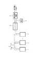
図1は、本発明の太陽電池モジュールを用いた太陽光発電システム全体の概念的な構成図である。図1において、1は太陽電池モジュールであり、複数の太陽電池モジュール1,1,…が、正側の芯線2P及び負側の芯線2Mを有する接続ケーブル2に夫々並列接続されている。接続ケーブル2としては、例えば2芯HCVケーブルのような2芯のケーブルを用いても良いし、1芯HCVケーブルのような1芯のケーブルを2本用いても良い。複数の太陽電池モジュール1,1,…からの直流出力は、接続ケーブル2を通じてインバータ3に供給されて交流出力に変換された後に、負荷5または連系保護装置4を介して商用電力系統へ送られる。
【0036】
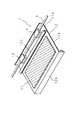
図2は、第1の実施の形態に係る太陽電池モジュール1の外観を示す斜視図である。図2には参考のために接続ケーブル2も併せて示している。図2に示す如く、太陽電池モジュール1は、結晶シリコンまたは非晶質シリコン等の光電変換材料からなる太陽電池を有する太陽電池部11が、例えば鋼板製の支持体12上に接着されて構成されている。この支持体12は、太陽電池部11が接着される平板部12aと、その軒側及び棟側に夫々設けられた立下り部12b及び立上り部12cとを有しており、軒側の太陽電池モジュール1の立上り部12cに棟側の太陽電池モジュール1の立下り部12bを係合させた態様にて、複数の太陽電池モジュール1を家屋の屋根上等に階段状に設置できるようになっている。
【0037】
また、支持体12は立上り部12cの更に棟側に延在部12dを有しており、この延在部12dの棟側端部は上方に折り曲げられている。延在部12dには、太陽電池モジュール1を接続ケーブル2に電気的に接続するための正負一対の配線接続部13,13が設けられており、これら配線接続部13,13は図示しない接続用配線によって太陽電池部11に接続されている。
【0038】
次に、配線接続部13の構成について図3〜図6を参照して詳細に説明する。図3は、配線接続部13の外観を示す斜視図であり、参考のために接続ケーブル2も併せて示している。図3に示す如く、配線接続部13は、略直方体の形状を有しており、夫々絶縁性を有するプラスチック樹脂よりなる本体13aと上蓋13bとから構成される。また、側面には接続ケーブル2を挿通させるための開口部13cが形成されている。
【0039】
図4は、負側に用いる配線接続部13における本体13aを上方から見た平面図である。図4においては参考のために、例えば2芯のケーブルを用いた接続ケーブル2を一点鎖線で示しており、接続ケーブル2は、夫々破線で示す負側の芯線2M及び正側の芯線2Pを被覆2Cで封着した構成をなしている。なお、前述したように接続ケーブル2として1芯のケーブル2本を用いても良い。
【0040】
図4において、101及び201は何れも金属性のネジであり、本体13a内の底面から起立して設けられたプラスチック樹脂製の支持台(図示せず)にネジ止めされている。そして、これらのネジ101とネジ201とによって、第1の接続領域102a及び第2の接続領域102bを有する第1の金属板102と、第3の接続領域202a及び第4の接続領域202bを有する第2の金属板202とが夫々ネジ止めされている。このように、第1の金属板102及び第2の金属板202は、本体13aの底面から起立して設けられたプラスチック樹脂製の支持台にネジ止めされているので、弾力性を有している。
【0041】
第1の金属板102における第2の接続領域102bと、第2の金属板202における第4の接続領域202bとの間には、逆流防止ダイオード103が接続されている。この逆流防止ダイオード103は負側の配線接続部13にのみ設ければ良く、正側の配線接続部13には設ける必要がない。正側の配線接続部13の場合には第2の接続領域102bと第4の接続領域202bの間は単に金属板によって接続される。
【0042】
また、第1の金属板102における第1の接続領域102aには太陽電池部11から引き出された負側の接続用配線が接続され、第2の金属板202における第3の接続領域202aは、後述するように接続ケーブル2の負側の芯線2Mと電気的に接続される。
【0043】
図5は、負側に用いる配線接続部13における上蓋13bの平面図であり、図6は図5におけるVI−VI線の断面図である。これらの図5, 図6においても接続ケーブル2を併せて示しており、更に、図6においては参考のために本体13aの断面も併せて示している。
【0044】
図5,図6において301は断面コ字状の形状を有する金属製の接続部材であり、図中破線で示す如く大半が上蓋13b内に埋設されている。そして、接続ケーブル2における負側の芯線2Mに対応する位置、及び、本体13aに設けられた第2の金属板202における第3の接続領域202aに対応する位置で、その先端部が上蓋13bから本体13a側に突出している。なお、この構成は負側の配線接続部13に関するものであり、正側の配線接続部13にあっては負側の芯線2Mに対応する位置ではなく、正側の芯線2Pに対応する位置でその先端部が上蓋13bから突出している。
【0045】
次に、以上のような構成の配線接続部13を用いて太陽モジュール1と接続ケーブル2との接続を行う方法について説明する。
【0046】
まず、正側,負側の配線接続部13,13の上蓋13b,13bを外して開口部13c,13c内に接続ケーブル2を配置する。次いで、上蓋13b,13bを閉じることにより、上蓋13b,13bから突出する接続部材301,301における一方の先端部が、夫々第2の金属板202における第3の接続領域202aと接触する。この際、第2の金属板202が有する弾力性によって第3の接続領域202aと接続部材301との接続が保たれる。また、正側,負側の上蓋13b,13bから突出する接続部材301,301の他方の先端部は、接続ケーブル2の被覆2Cを貫通し、夫々正側,負側の芯線2P,2Mに圧接され、これら芯線2P,2Mと電気的に接続されることになる。
【0047】
以上のように、第1の実施の形態によれば、配線接続部13の上蓋13bを閉める作業によって同時に接続部材301を接続ケーブル2の被覆2Cを貫通させて芯線2Pまたは2Mと電気的に接続させることができるので、太陽電池モジュール1と接続ケーブル2との接続処理が極めて容易となる。また、従来のようにコネクタを使用しないのでコストの低減化を図ることができる。更に、接続部材301が接続ケーブル2の被覆2Cに埋設されることとなるので防水性も向上する。
【0048】
上述した例では、正側の配線接続部13と負側の配線接続部13とを別々に設けた場合について説明したが、1つの配線接続部13に正負一対の接続部材301,301を備える構成としても良いことは言うまでもない。
【0049】
(第2の実施の形態)
次に、本発明の第2の実施の形態について、図7〜図11を参照して説明する。前述した第1の実施の形態にあっては太陽電池モジュール1を接続ケーブル2に並列接続する例について説明したが、この第2の実施の形態は、複数の太陽電池モジュール1を直列接続する点で、第1の実施の形態と相違している。
【0050】
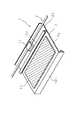
図7は、第2の実施の形態に係る太陽電池モジュール1の外観を示す斜視図であり、図2と同一の機能を呈する部分には同一の符号を付している。図7に示す如く、この第2の実施の形態に係る太陽電池モジュール1においても、太陽電池部11が支持体12上に接着されており、図示しない接続用配線によって太陽電池部11と接続された配線接続部13が延在部12d上に設けられている。この配線接続部13は、第1の実施の形態と同様の図3に示す外観を有しており、略直方体の形状であって、夫々絶縁性を有するプラスチック樹脂よりなる本体13aと上蓋13bとから構成されている。また、側面には接続ケーブル2を挿通させるための開口部13cが形成されている。
【0051】
次に、第2の実施の形態における配線接続部13について図8〜図11を参照して詳細に説明する。図8は、本体13aを上方から見た平面図である。参考のために接続ケーブル2を一点鎖線で示している。第2の実施の形態にあっては、接続ケーブル2として1芯のケーブルを用いており、接続ケーブル2は、破線で示す芯線21を被覆22で封着した構成をなしている。
【0052】
図8において、401及び501は何れも金属製のネジであり、本体13a内の底面から起立して設けられたプラスチック樹脂製の支持台(図示せず)にネジ止めされている。そして、これらネジ401とネジ501とによって、第1の接続領域402a,第2の接続領域402b及び第3の接続領域402cを有する第1の金属板402と、第4の接続領域502a,第5の接続領域502b及び第6の接続領域502cを有する第2の金属板502とがネジ止めされている。このように、第1の金属板402及び第2の金属板502は、本体13aの底面から起立して設けられた支持台にネジ止めされているので、弾力性を有している。
【0053】
第1の金属板402における第2の接続領域402bには太陽電池部11からの正側の接続用配線(図示せず)が接続され、第2の金属板502における第5の接続領域502bには太陽電池部11からの負側の接続用配線(図示せず)が接続される。また、第1の金属板402における第3の接続領域402cと第2の金属板502における第6の接続領域502cとの間には、バイパスダイオード503が接続されている。また、第1の金属板402における第1の接続領域402a及び第2の金属板502における第4の接続領域502aには、後述するように接続ケーブル2の芯線21が接続される。
【0054】
図9は、上蓋13bの平面図であり、図10は図9におけるX−X線の断面図、図11は図9におけるXI−XI線の断面図である。これらの図9〜図11においても接続ケーブル2を示しており、図10,図11においては本体13aの断面も併せて示している。
【0055】
これらの図において601,601は金属製の接続部材であり、互いに電気的に分離されている。接続部材601,601は、何れも図中破線で示す如く大半が上蓋13b内に埋設されており、接続ケーブル2における芯線21に対応する位置、及び、第1の金属板402における第1の接続領域402aに対応する位置または第2の金属板502における第4の接続領域502aに対応する位置で、その先端部が上蓋13bから本体13a側に突出している。
【0056】
また、これら接続部材601,601の間であって、接続ケーブル2に対応する位置には、この接続ケーブル2を切断するための絶縁性の切断部材602が上蓋13bから突出して設けられている。この切断部材602としては、例えばセラミックカッターを用いることができる。
【0057】
次に、第2の実施の形態における太陽電池モジュール1と接続ケーブル2との接続を行う方法について説明する。
【0058】
まず、配線接続部13の上蓋13aを外して開口部13c内に接続ケーブル2を配置する。次いで、上蓋13aを閉じることにより、上蓋13aから突出する接続部材601,601の先端部が、何れも接続ケーブル2の被覆22を貫通して芯線21と接触すると共に、夫々第1の金属板402における第1の接続領域402a、第2の金属板502における第4の接続領域502aと接触する。この際、第1の金属板402,第2の金属板502が有する弾力性によって、接続部材601,601と第1の接続領域402a,第4の接続領域502aとの接続が保たれる。このようにして、第1の接続領域402aと第4の接続領域502aとの間が、接続部材601,601を介して接続ケーブル2の芯線21と電気的に接続される。
【0059】
更に、切断部材602により接続部材601,601間で接続ケーブル2が切断されることによって、太陽電池モジュール1が接続ケーブル2に直列接続されることとなる。切断部材602の側面に、ブチルゴムまたは絶縁油等を予め塗布しておくと、切断後に接続ケーブル2の切断面の防水性を向上させることができるので好ましい。
【0060】
以上のように、第2の実施の形態にあっても、第1の実施の形態と同様に、太陽電池モジュール1と接続ケーブル2との電気的接続処理が極めて容易であり、コネクタを使用しないのでコストの低減化を図れ、接続部材601が接続ケーブル2の被覆22に埋設されることとなるので防水性も向上する。
【0061】
第1及び第2の何れの実施の形態においても、配線接続部13を必ずしも支持体12上に設ける必要はないが、配線接続部13を支持体12上に設けた太陽電池モジュール1によれば、持ち運びが容易となり、作業性を向上させることができるので好ましい。また、本発明に係る太陽電池モジュールは、接続ケーブルの被覆を貫通してその芯線と電気的に接続する接続部材を有するものであれば良く、上記第1の実施の形態及び第2の実施の形態で説明した構成のものに限られることはない。例えば、接続部材を上蓋ではなく本体に設けたものであっても、本発明に含まれることは言うまでもない。
【0062】
(第3の実施の形態)
次に、複数の太陽電池モジュール1の設置方法である本発明の第3の実施の形態について、図12を参照して説明する。
【0063】
図12は、屋根の軒棟方向に階段状に配置された隣合う太陽電池モジュール1,1の要部を示す図である。第1,第2の実施の形態と同様に、太陽電池モジュール1は、結晶シリコンまたは非晶質シリコン等の光電変換材料からなる太陽電池を有する太陽電池部11が、例えば鋼板製の支持体12上に接着されて構成されている。この支持体12は、太陽電池部11が接着される平板部12aと、その軒側及び棟側に夫々設けられた立下り部12b及び立上り部12cとを有しており、軒側(下側)の太陽電池モジュール1の立上り部12cに棟側(上側)の太陽電池モジュール1の立下り部12bが係合されるようになっている。
【0064】
また、支持体12は立上り部12cの更に棟側に延在部12dを有しており、この延在部12dの棟側端部は上方に折り曲げられている。延在部12dには、太陽電池モジュール1を接続ケーブル2に電気的に接続するための配線接続部23が設けられている。太陽電池モジュール1の延在部12dと反対側の端部には、太陽電池部11及びその下方の支持体12(平板部12a)を貫通する孔1aが形成されており、この孔1aを通ったビス901の固定により、太陽電池モジュール1が野地板902に設置されるようになっている。太陽電池モジュール1のこの孔1aの周縁部には、防水シール材903が設けられている。
【0065】
配線接続部23は、断面がコ字状をなす上蓋23aと、同じく断面がコ字状をなしており、上蓋23aよりサイズが小さい下蓋23bとから構成されており、下蓋23bに上蓋23aを被せることができる。この配線接続部23内には、正側の芯線24Pを被覆24Cで封着した構成を有する正側の接続ケーブル24と負側の芯線25Mを被覆24Cで封着した構成を有する負側の接続ケーブル25とが、並設して挿通されている。下蓋23bの内面には、各1芯の接続ケーブル24,25の芯線24P,25Mに対応する位置に、ピン状の接続部材701,801が上蓋23a側に突出し態様で設けられている、この接続部材701には軒側(下側)の太陽電池モジュール1の太陽電池部11から引き出された正側の接続用配線(図示せず)が接続され、接続部材801には同じく太陽電池部11から引き出された負側の接続用配線(図示せず)が接続されている。
【0066】
上蓋23aの内面には、接続ケーブル24,25に対応する位置に、後述するビス止め固定時に接続ケーブル24,25を押圧する押圧部材26,27が形成されている。また、上蓋23a及び下蓋23bには、接続ケーブル24,25の中間に対応する位置に、ビス901が挿通するための孔28及び孔29が形成されている。
【0067】
次に、以上のような構成の複数の太陽電池モジュール1を野地板902に設置する方法について説明する。
【0068】
軒側の太陽電池モジュール1を野地板902上に配設し、配線接続部23の下蓋23bに正負各1本ずつの接続ケーブル24,25を配置する。次いで、孔28及び孔29の位置を合わせて、上蓋23aを下蓋23bに被せる。この際、押圧部材26,27は接続ケーブル24,25に軽く触れている程度であり、接続部材701,801も接続ケーブル24,25の周面に接触しているだけであって芯線24P,25Mまでは達していない。
【0069】
軒側の太陽電池モジュール1の延在部12d上に、その軒側部分(下側部分)が重なるように、棟側の太陽電池モジュール1を配設する。この際、棟側の太陽電池モジュール1の孔1aと軒側の太陽電池モジュール1の配線接続部23の孔28,孔29との位置合わせを行うと共に、軒側の太陽電池モジュール1の立上がり部12cに棟側の太陽電池モジュール1の立下がり部12bを係合させる。
【0070】
その後、ビス901を孔1a,孔28,孔29に挿通させ、その先端部が野地板902まで入り込むように、挿通したビス901を締め付けて、棟側の太陽電池モジュール1の軒側部分を固定すると共に、軒側の太陽電池モジュール1を野地板902に固定する。この際、ビス901の締め付けによって、軒側の太陽電池モジュール1の立上がり部12cと棟側の太陽電池モジュール1の立下がり部12bとの係合が強くなって、高い防水性を確保できる。
【0071】
また、次のような作用によって、軒側の太陽電池モジュール1と接続ケーブル24,25(芯線24P,25M)との電気的接続も同時に実現できる。ビス901の締め付けを行うことにより、配線接続部23の上蓋23aが押し下げられ、押圧部材26,27が接続ケーブル24,25を下方に押圧する。この結果、接続部材701,801が接続ケーブル24,25の被覆24C,25Cを貫通して芯線24P,25Mに接触する。
【0072】
以上のように、第3の実施の形態では、太陽電池モジュール1の固定と、軒棟方向に隣合う太陽電池モジュール1,1間の防水性の確保と、太陽電池モジュール1の接続ケーブル24,25との電気的接続とを同時に行うことができ、作業効率が極めて高くなり、複数の太陽電池モジュール1の設置作業に要する時間を大幅に短縮できる。
【0073】
また、ビス901を緩めることにより、軒側の太陽電池モジュール1を簡単に取り外すことができ、1枚ずつの太陽電池モジュール1の交換を容易に行える。またこの際、接続ケーブル24,25との電気的接続の切り離しも同時に行えて作業効率が良い。
【0074】
(第4の実施の形態)
図13は、第4の実施の形態に係る太陽電池モジュール1の外観を示す斜視図である。図13において図2と同一部分には同一の符号を付してそれらの説明を省略する。図13において、32は接続ケーブル2と並設されたアース線である。この第4の実施の形態では、第1の実施の形態と同様に、太陽電池モジュール1を接続ケーブル2に電気的に接続するための正負一対の配線接続部13,13が延在部12dに設けられているが、その何れか一方の配線接続部13は、太陽電池モジュール1のアースを取る、つまり太陽電池モジュール1とアース線32とを接続させるためのアース接続部の機能も果たす。
【0075】
次に、配線接続及びアース接続の両方の機能を果たす配線接続部13の構成について図14〜図18を参照して詳細に説明する。なお、図14〜図18において、図3〜図6と同一部分は同一符号を付している。図14は、この配線接続部13の外観を示す斜視図であり、参考のために接続ケーブル2及びアース線32も併せて示している。図14に示す如く、配線接続部13は、略直方体の形状を有しており、夫々絶縁性を有するプラスチック樹脂よりなる本体13aと上蓋13bとから構成される。配線接続部13の側面には、接続ケーブル2,アース線32を夫々挿通させるための開口部13c,13dが形成されている。また、上蓋13bには、後述するビスが挿通するための孔13eが形成されている。
【0076】
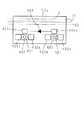
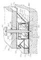
図15は配線接続部13における本体13aを上方から見た平面図、図16は配線接続部13における上蓋13bの平面図である。また、図17は図16におけるXVII−XVII線の断面図、図18は図16におけるXVIII −XVIII 線の断面図である。図15,図16においては、図4,図5と同様な2芯のケーブルを用いた接続ケーブル2と、破線で示す芯線32aを被覆32bで封着した構成をなすアース線32とを夫々一点鎖線で示している。また、図18においては、固定用のビス51,支持体12の延在部12d及び設置対象の野地板902も示している。
【0077】
41は金属製のアース接続部材、42はアース接続部材41に連なるビス留め部である。アース接続部材41は、アース線32の芯線32aに対応する位置に延びているアース接続針71を有する。孔13e及びビス留め部42にビス51を挿入して固定することにより、アース接続部材41とその下方の延在部12dとが導通すると共に、延在部12dが下方の野地板902に固定されるようになっている。
【0078】
次に、以上のような構成の配線接続部13を用いて、太陽電池モジュール1と接続ケーブル2との接続、及び、太陽電池モジュール1とアース線32との接続を同時に行う方法について説明する。なお、太陽電池モジュール1と接続ケーブル2との接続処理の手順は第1の実施の形態の場合と同様であるので、その詳細については説明を省略する。
【0079】
まず、配線接続部13の上蓋13bを外して開口部13c内に接続ケーブル2及び開口部13d内にアース線32を夫々配置する。次いで、上蓋13bを閉じることにより、アース接続部材41のアース接続針71がアース線32に接触し、更に、その先端部は、アース線32の被覆32bを貫通して芯線32aに圧接され、芯線32aと電気的に接続される。
【0080】
そして、ビス51を用いて、上蓋13b側から孔13e及びビス留め部42を介して延在部12dを貫通して野地板902に達するまで、ビス留め固定を行う。このビス留め固定により、アース線32の芯線32aに接続されたアース接続部材41と延在部12dとが導通して、太陽電池モジュール1がアース線32と電気的に接続し、太陽電池モジュール1のアースを取れるようになる。また、このビス留め固定により、同時に、延在部12dが野地板902に設置固定、つまり、太陽電池モジュール1が野地板902に設置固定されることになる。
【0081】
以上のように、第4の実施の形態によれば、配線接続部13の上蓋13bを閉める作業によってアース接続部材41をアース線32の被覆32bを貫通させて芯線32aと電気的に接続させることができるので、太陽電池モジュール1とアース線32との接続処理が極めて容易となる。また、1回のビス留め固定によって、アース線32と太陽電池モジュール1(延在部12d)との導通、及び、太陽電池モジュール1の野地板902への固定を同時に行えるので、作業効率が極めて高い。
【0082】
上述した例では、第1の実施の形態(複数の太陽電池モジュール1を接続ケーブル2に並列接続する例)に応じて、太陽電池モジュール1のアースを取る場合について説明したが、第2の実施の形態(複数の太陽電池モジュール1を接続ケーブル2に直列接続する例)についても、同様に、共通の配線接続部13を用いてケーブル接続とアース接続とを併せて行うような構成が可能であることは勿論である。
【0083】
(第5の実施の形態)
上述した第4の実施の形態によるアース接続の例では、ケーブル接続と共通の配線接続部13を利用するようにしたが、ケーブル接続に用いる配線接続部13とは異なるアース接続部を独立に設けてアース接続を行うようにしても良いことは言うまでもない。
【0084】
以下、このようにしたアース接続の例について説明する。図19(a)はアース接続部の一例を示す正面図、図19(b)は図19(a)のb−b線における断面図である。図19(b)には、太陽電池部が設けられていない延在部12d及び太陽電池モジュール1が設置固定される野地板902も併せて図示している。
【0085】
アース接続部61は、上蓋61aと下蓋61bとビス留め部62とを有し、これらの上蓋61a,下蓋61b間の空隙を、芯線32aを被覆32bで封着したアース線32が通る。上蓋61aには、アース線32の芯線32aに対応する位置にアース接続針71が突出している。
【0086】
次に、以上のような構成のアース接続部61を用いて、太陽電池モジュールとアース線32とのアース接続を行う方法について説明する。まず、ビス留め部62及び延在部12dにビス51を野地板902に達するまで貫通させて、図19(b)に示すように上蓋61aを開けた状態で、アース接続部61を延在部12dに取り付ける。この結果、延在部12dとビス留め部62とが電気的に接続される。また、このビス留めにより、延在部12dが野地板902に固定されるため、同時に、太陽電池モジュール1を野地板902に設置固定できる。
【0087】
次いで、アース線32をアース接続部61の中を通して配置し、図19(b)の破線に示す如く、上蓋61aを閉じることにより、アース接続針71がアース線32の被覆32bを貫通して芯線32aと電気的に接続される。この結果、延在部12dがアース線32と電気的に接続され、太陽電池モジュール1のアースを取ることができる。
【0088】
この例にあっても、アース接続部61の上蓋61aを閉める作業によってアース接続針71がアース線32の被覆32bを貫通して芯線32aと電気的に接続されるので、太陽電池モジュール1とアース線32との接続処理が極めて容易となり、コストの低減化も図ることができる。また、1回のビス留め固定によって、アース線32と太陽電池モジュール1(延在部12d)との導通、及び、太陽電池モジュール1の野地板902への固定を同時に行えるので、作業効率が極めて良い。
【0089】
なお、上記例では、ビス留めによりアース接続部61を延在部12dに固定する場合について説明したが、溶接等の他の手法でアース接続部61を延在部12dに電気的に接続させてビス留めを省くことも可能である。
【0090】
【発明の効果】
以上詳述したように、本発明の太陽電池モジュールでは、ケーブルの被覆を貫通して芯線と電気的に接続する接続部材を備えるようにしたので、ケーブルとの接続を極めて容易に行うことができる。また、従来のようにコネクタを使用しないのでコストの低減化を図ることができる。更に、接続部材がケーブルの被覆に埋設されることとなるので、防水性も向上することができる。
【0091】
また、本発明の太陽電池モジュールの接続方法では、太陽電池モジュールを極めて容易にケーブルと並列または直列接続することが可能となり、配線の作業性を向上させることができる。
【0092】
また、本発明の太陽電池モジュールの設置方法では、上側の太陽電池モジュールの下側部分と下側の太陽電池モジュールの上側部分との重ね合わせ部分をビスにて設置体に固定するようにしたので、ビスを緩めることにより、下側の太陽電池モジュールを簡単に取り外すことができ、1枚ずつの太陽電池モジュールの交換を容易に行える。また、固定処理と同時に、防水処理及び電気的接続処理も行えるので、複数の太陽電池モジュールを設置するための作業時間を大幅に短縮することが可能となる。
【0093】
また、本発明の太陽電池モジュールでは、アース線の被覆を貫通して芯線と電気的に接続するアース接続部材を備えるようにしたので、アース線との接続を極めて容易に行うことができる。
【0094】
また、本発明の太陽電池モジュールのアース接続方法では、太陽電池モジュールのアース接続部材をアース線の被覆を貫通させて芯線に圧接させて、太陽電池モジュール(支持体)とアース線との電気的接続を得るようしたので、容易かつ低コストにて各太陽電池モジュールのアースを取ることができる。
【0095】
更に、本発明の太陽電池モジュールの設置方法では、1つのビス留めにより太陽電池モジュールの支持体とアース接続部材との電気的接続、及び、太陽電池モジュールの設置体への固定を同時に行えるので、作業効率を向上することができる。
【図面の簡単な説明】
【図1】太陽光発電システムの概念的な構成図である。
【図2】第1の実施の形態に係る太陽電池モジュールの斜視図である。
【図3】配線接続部の斜視図である。
【図4】配線接続部の本体の平面図である。
【図5】配線接続部の上蓋の平面図である。
【図6】図5におけるVI−VI線の断面図である。
【図7】第2の実施形態に係る太陽電池モジュールの斜視図である。
【図8】配線接続部の本体の平面図である。
【図9】配線接続部の上蓋の平面図である。
【図10】図9におけるX−X線の断面図である。
【図11】図9におけるXI−XI線の断面図である。
【図12】屋根の軒棟方向に階段状に配置された隣合う太陽電池モジュールの要部を示す図である。
【図13】第4の実施の形態に係る太陽電池モジュールの斜視図である。
【図14】配線接続部の斜視図である。
【図15】配線接続部の本体の平面図である。
【図16】配線接続部の上蓋の平面図である。
【図17】図16におけるXVII−XVII線の断面図である。
【図18】図16におけるXVIII −XVIII 線の断面図である。
【図19】第5の実施の形態に係るアース接続部の概略図である。
【符号の説明】
1 太陽電池モジュール
1a,28,29 孔
2,24,25 接続ケーブル
2P,2M,21,24P,25M,32a 芯線
2C,22,24C,25C,32b 被覆
11 太陽電池部
12 支持体
13,23 配線接続部
13a 本体
13b,23a,61a 上蓋
23b,61b 下蓋
26,27 押圧部材
32 アース線
41 アース接続部材
42,62 ビス留め部
51,901 ビス
61 アース接続部
71 アース接続針
301,501,601,701,801 接続部材
602 切断部材
902 野地板[0001]
TECHNICAL FIELD OF THE INVENTION
The present invention relates to a solar cell module connected to a cable for connecting solar cell modules to each other, a connection method thereof, and a solar cell module in which a plurality of solar cell modules are installed on an installation body such as a roof of a house without using a base. The present invention relates to a solar cell module connected to a ground line for grounding, and a ground connection method thereof.
[0002]
[Prior art]
2. Description of the Related Art Photovoltaic power generation, which converts light energy into electric energy using the photoelectric conversion effect, is widely used as a means for obtaining clean energy. With the improvement of the photoelectric conversion efficiency of the solar cell, a solar power generation system has been provided in many private houses.
[0003]
In such a solar power generation system, a plurality of solar cell modules each having a solar cell unit in which a plurality of stages of solar cells are connected in series are connected to a main cable, and collected via the main cable. The DC output of the solar cell module is converted into an AC output by an inverter and output.
[0004]
2. Description of the Related Art A method of connecting a plurality of solar cell modules to a main cable to facilitate wiring when connecting the plurality of solar cell modules is known (for example, Japanese Patent Application Laid-Open No. 11-299126). In such a conventional connection method, the male or female connector provided on the trunk cable side is connected to the female or male connector provided on the solar cell module side, so that the solar module can be easily connected to the solar cell module. The battery module can be connected to the mains cable.
[0005]
In addition, in a photovoltaic power generation system for a private house, in addition to the method of installing multiple solar cell modules on a metal gantry, multiple solar cell modules can be directly attached to a roof building material (field board) without installing a gantry. Installation methods are also being implemented.
[0006]
[Problems to be solved by the invention]
In the above-described conventional connection method of the solar cell module, there is a problem that the male and female connectors to be used are expensive in order to improve the waterproof performance, and also the waterproof performance at the connection part is also high. There is still room for improvement.
[0007]
In the installation method in which a plurality of solar cell modules are installed on the ground board, in order to make the appearance similar to that of the roof, stairs are moved from the ridge side to the eave side with the ends of adjacent solar cell modules superimposed. In many cases, a so-called stepping structure in which a plurality of solar cell modules are installed in a shape is adopted. At this time, since the waterproofness is obtained by fitting the adjacent solar cell modules, it is difficult to replace one solar cell module at a time, and it is not possible to efficiently cope with a failure or poor installation of the solar cell module. There's a problem. Further, there is a problem that the work at the time of installation is complicated, and the processing takes a long time.
[0008]
When a plurality of solar cell modules are installed on a metal base, the metal frame around each solar cell module is fixed to the base, so that the surroundings of each solar cell module and the base are equal. Since the pedestal itself is connected to a ground line because of the potential, each solar cell module can be grounded. On the other hand, when a plurality of solar cell modules are directly installed on a building material (field board) on a roof, a stand is not provided. It is necessary to separately provide a wiring for connection to a ground line, and simplicity is required for connection to this ground line.
[0009]
The present invention has been made in view of such circumstances, and can be easily and at low cost to connect with a cable for connecting solar cell modules, and a solar cell module with high waterproofness at the connection portion and The purpose is to provide a connection method.
[0010]
Another object of the present invention is to provide a method for installing a solar cell module in which the solar cell modules can be easily replaced one by one, and the time required for installing a plurality of solar cell modules is short.
[0011]
Still another object of the present invention is to provide a solar cell module which can be easily and inexpensively connected to a ground wire, and a method for connecting the ground to the solar cell module.
[0012]
[Means for Solving the Problems]
The solar cell module according to
[0013]
The solar cell module according to the first aspect includes a connection member that penetrates through the sheath of the cable and electrically connects to the core wire, so that electrical connection can be easily obtained. It is unnecessary and cost is reduced. Furthermore, since the connecting member is embedded in the cable sheath, the waterproofing at the connecting portion is high.
[0016]
[0017]
[0018]
[0019]
[0020]
Claim4 The connection method of the solar cell module according to the
[0021]
Claim4 In the connection method of the solar cell module, the connection member of the solar cell module is penetrated through the sheath of the cable and pressed against the core wire to obtain an electrical connection between the solar cell module and the cable. Therefore, electrical connection can be easily performed, and a connector as in the related art is not required and the cost is low. Furthermore, since the connecting member is embedded in the cable sheath, the waterproofing at the connecting portion is high.
[0022]
Claim5 The installation method of the solar cell module according toIt is a method of installing the solar cell module according to any one of
[0025]
Claim5 In the installation method of the solar cell module, when fixing with a screw,Thick The positive cell module is electrically connected to the cable. Therefore, the fixing process and the electrical connection process can be performed simultaneously, and the installation work of the solar cell module can be performed efficiently. Also, the electrical connection can be easily cut off only by loosening the screws.
[0026]
Claim6 The solar cell module according toA metal support, provided on the support, a solar cell portion having a solar cell, Solar cell module connected to earth wire with core wire sealed with coatingAnd a ground connection portion connected to the support and connected to the ground wire, the ground connection portion being a surface of the support on the same side as a surface on which the solar cell portion is provided. An upper body, an upper lid, a ground connection member electrically connected to the ground wire, and an opening for inserting the ground wire, wherein the ground connection member is connected to the ground connection. By closing the main body and the upper lid of the ground connection portion in a state where the ground wire is inserted in the portion, Electrically connected to the core wire of the ground wire through the cover of the ground wireIs characterized by .
[0027]
Claim6 In the case of the solar cell module of
An earth connection member for electrical connection is provided, so that the earth connection can be easily obtained.
[0030]
Claim7 The method for earth connection of a solar cell module according to6 A method for connecting the solar cell module described in the above to a ground wire,By closing the main body and the upper lid of the ground connection portion in a state where the ground wire is inserted into the ground connection portion, A ground connection member is pressed into contact with the core wire of the ground wire through the cover of the ground wire.At least The solar cell module is connected to the ground wire.
[0031]
Claim7 In the method of earth connection of the solar cell module described above, the ground connection member of the solar cell module is made to penetrate through the covering of the earth wire and is pressed against the core wire to electrically connect the solar cell module (support) to the earth wire. Get. Therefore, the ground of each solar cell module can be easily taken.
[0032]
Claim8 The installation method of the solar cell module according to the claim6 A method for installing the solar cell module according to the above to the installation body,In a state where the ground wire is inserted into the ground connection portion, the upper lid of the ground connection portion is screwed with a screw that passes through the support plate and reaches the installation body, thereby connecting the ground connection member to the ground wire. At the same time as penetrating the sheath and electrically connecting to the core wire of the ground wire, Fixing to the installation bodyTo It is characterized by performing.
[0033]
Claim8 In the method of installing the solar cell module, the support of the solar cell module and the ground connection member are electrically connected by screwing, and at the same time, the solar cell module is installed and fixed to the installation body by the screwing. Is done. Therefore, special processing for obtaining the connection between the support and the ground connection member is not required, and the ground connection processing can be performed efficiently.
[0034]
BEST MODE FOR CARRYING OUT THE INVENTION
Hereinafter, the present invention will be specifically described with reference to the drawings showing the embodiments.
[0035]
(First Embodiment)
FIG. 1 is a conceptual configuration diagram of an entire photovoltaic power generation system using the solar cell module of the present invention. In FIG. 1,
[0036]
FIG. 2 is a perspective view illustrating an appearance of the
[0037]
The
[0038]
Next, the configuration of the
[0039]
FIG. 4 is a plan view of the main body 13a of the
[0040]
In FIG. 4,
[0041]
A
[0042]
Further, the first connection region 102a in the
[0043]
FIG. 5 is a plan view of the
[0044]
In FIGS. 5 and 6,
[0045]
Next, a method of connecting the
[0046]
First, the
[0047]
As described above, according to the first embodiment, the work of closing the
[0048]
In the example described above, the case where the positive-side
[0049]
(Second embodiment)
Next, a second embodiment of the present invention will be described with reference to FIGS. In the above-described first embodiment, the example in which the
[0050]
FIG. 7 is a perspective view illustrating an appearance of a
[0051]
Next, the
[0052]
In FIG. 8,
[0053]
The positive connection wiring (not shown) from the
[0054]
9 is a plan view of the
[0055]
In these figures,
[0056]
An insulating cutting
[0057]
Next, a method for connecting the
[0058]
First, the upper cover 13a of the
[0059]
Further, by cutting the
[0060]
As described above, also in the second embodiment, similarly to the first embodiment, the electrical connection between the
[0061]
In any of the first and second embodiments, it is not necessary to provide the
[0062]
(Third embodiment)
Next, a third embodiment of the present invention, which is a method for installing a plurality of
[0063]
FIG. 12 is a diagram showing a main part of adjacent
[0064]
The
[0065]
The
[0066]
On the inner surface of the upper lid 23a, pressing
[0067]
Next, a method of installing the plurality of
[0068]
The
[0069]
The
[0070]
Thereafter, the
[0071]
Further, by the following operation, electrical connection between the
[0072]
As described above, in the third embodiment, the
[0073]
In addition, by loosening the
[0074]
(Fourth embodiment)
FIG. 13 is a perspective view illustrating an appearance of a
[0075]
Next, the configuration of the
[0076]
FIG. 15 is a plan view of the main body 13 a of the
[0077]
[0078]
Next, a method for simultaneously connecting the
[0079]
First, the
[0080]
Then, using the
[0081]
As described above, according to the fourth embodiment, the work of closing the
[0082]
In the example described above, the case where the
[0083]
(Fifth embodiment)
In the example of the ground connection according to the fourth embodiment described above, the common
[0084]
Hereinafter, an example of such a ground connection will be described. FIG. 19A is a front view illustrating an example of the ground connection portion, and FIG. 19B is a cross-sectional view taken along line bb of FIG. 19A. FIG. 19 (b) also shows the extending
[0085]
The
[0086]
Next, a method of connecting the solar cell module and the
[0087]
Next, the
[0088]
Also in this example, since the
[0089]
In the above example, the case where the
[0090]
【The invention's effect】
As described above in detail, in the solar cell module of the present invention, since the connection member that penetrates the coating of the cable and is electrically connected to the core wire is provided, the connection with the cable can be performed extremely easily. . In addition, since a connector is not used unlike the related art, cost can be reduced. Furthermore, since the connecting member is embedded in the covering of the cable, the waterproofness can be improved.
[0091]
Further, according to the method for connecting a solar cell module of the present invention, the solar cell module can be very easily connected in parallel or in series with a cable, and the workability of wiring can be improved.
[0092]
In the method for installing a solar cell module according to the present invention, the overlapping portion of the lower part of the upper solar cell module and the upper part of the lower solar cell module is fixed to the installation body with screws. By loosening the screws, the lower solar cell module can be easily removed, and the solar cell modules can be easily replaced one by one. In addition, since the waterproofing process and the electrical connection process can be performed simultaneously with the fixing process, the working time for installing a plurality of solar cell modules can be significantly reduced.
[0093]
Further, the solar cell module of the present invention is provided with the ground connection member that penetrates the covering of the ground wire and is electrically connected to the core wire, so that the connection with the ground wire can be performed extremely easily.
[0094]
Further, in the method for connecting the ground of the solar cell module according to the present invention, the ground connection member of the solar cell module is made to penetrate through the covering of the ground wire and is pressed against the core wire to electrically connect the solar cell module (support) and the ground wire. Since the connection is obtained, each solar cell module can be easily grounded at low cost.
[0095]
Furthermore, in the method for installing a solar cell module of the present invention, the electrical connection between the support of the solar cell module and the ground connection member and the fixing of the solar cell module to the installation body can be simultaneously performed by one screw fastening. Work efficiency can be improved.
[Brief description of the drawings]
FIG. 1 is a conceptual configuration diagram of a solar power generation system.
FIG. 2 is a perspective view of the solar cell module according to the first embodiment.
FIG. 3 is a perspective view of a wiring connection unit.
FIG. 4 is a plan view of a main body of the wiring connection unit.
FIG. 5 is a plan view of an upper lid of a wiring connection portion.
6 is a sectional view taken along line VI-VI in FIG.
FIG. 7 is a perspective view of a solar cell module according to a second embodiment.
FIG. 8 is a plan view of a main body of the wiring connection portion.
FIG. 9 is a plan view of an upper lid of a wiring connection portion.
FIG. 10 is a sectional view taken along line XX in FIG. 9;
FIG. 11 is a sectional view taken along line XI-XI in FIG. 9;
FIG. 12 is a diagram showing a main part of adjacent solar cell modules arranged in a stepwise manner in the direction of the eaves of the roof.
FIG. 13 is a perspective view of a solar cell module according to a fourth embodiment.
FIG. 14 is a perspective view of a wiring connection unit.
FIG. 15 is a plan view of a main body of the wiring connection portion.
FIG. 16 is a plan view of an upper lid of a wiring connection portion.
17 is a sectional view taken along line XVII-XVII in FIG.
18 is a sectional view taken along line XVIII-XVIII in FIG.
FIG. 19 is a schematic diagram of a ground connection unit according to a fifth embodiment.
[Explanation of symbols]
1 Solar cell module
1a, 28, 29 holes
2,24,25 connection cable
2P, 2M, 21, 24P, 25M, 32a Core wire
2C, 22, 24C, 25C, 32b coating
11 Solar cell part
12 Support
13,23 Wiring connection
13a body
13b, 23a, 61a Upper lid
23b, 61b Lower lid
26,27 pressing member
32 ground wire
41 Earth connection member
42,62 Screw fastening part
51,901 Screw
61 Ground connection
71 Ground connection needle
301, 501, 601, 701, 801 connecting member
602 cutting member
902 field board
Claims (8)
Translated fromJapanese該支持体上に設けられた、太陽電池を有する太陽電池部と、
を有し、前記太陽電池部で発電した電力を外部に出力すべく芯線を被覆で封着した構成のケーブルに接続される太陽電池モジュールであって、
前記太陽電池部と接続され、且つ前記ケーブルと接続される配線接続部を有し、
該配線接続部は、前記支持体における前記太陽電池部が設けられた面と同じ側の面上に設けられた本体と、上蓋と、前記ケーブルと電気的に接続される接続部材と、前記ケーブルを挿通するための開口部と、を備え、
前記接続部材は、前記配線接続部内に前記ケーブルを挿通した状態で当該配線接続部の前記本体と上蓋を閉じることにより、前記ケーブルの被覆を貫通して当該ケーブルの芯線と電気的に接続されることを特徴とする太陽電池モジュール。A support,
A solar cell unit having a solar cell provided on the support,
A solar cell module connected to a cable having a configuration in which a core wire is sealed with a coatingto output power generated by the solar cell unit to the outside,
A wiring connection unit connected to the solar cell unit and connected to the cable;
The wiring connection portion includes a main body provided on a surface of the support on the same side as a surface on which the solar cell portion is provided, a top cover, a connection member electrically connected to the cable, and the cable. And an opening for inserting the
It said connecting member, by closing the main body and the upper lid of the wiring connection portion while inserting the cable to the wiring connection portionis the core wire electrically connected tothe cable through the covering of the cable solar cell module, characterized inthat.
前記配線接続部内に前記ケーブルを挿通した状態で当該配線接続部の前記上蓋を前記本体にビス止めすることにより、前記接続部材を前記ケーブルの被覆を貫通せしめて当該ケーブルの芯線と電気的に接続すると同時に、By screwing the upper lid of the wiring connection portion to the main body while the cable is inserted into the wiring connection portion, the connection member penetrates the coating of the cable and is electrically connected to the core wire of the cable. At the same time
前記ビスの先端部を前記設置体まで入り込むように締め付けることで、当該設置体への固定も同時に行うことを特徴とする太陽電池モジュールの設置方法。A method for installing a solar cell module, wherein the screw is fastened so as to enter the installation body so that the screw is fixed to the installation body at the same time.
該支持体上に設けられた、太陽電池を有する太陽電池部と、A solar cell unit having a solar cell provided on the support,
を有し、芯線を被覆で封着した構成のアース線に接続される太陽電池モジュールであって、A solar cell module connected to a ground wire having a configuration in which a core wire is sealed with a coating,
前記支持体と接続され、且つ前記アース線と接続されるアース接続部を有し、Having a ground connection portion connected to the support and connected to the ground wire,
該アース接続部は、前記支持体における前記太陽電池部が設けられた面と同じ側の面上に設けられた本体と、上蓋と、前記アース線と電気的に接続されるアース接続部材と、前記アース線を挿通するための開口部と、を備え、The ground connection portion, a main body provided on the same surface of the support as the surface on which the solar cell portion is provided, a top cover, and a ground connection member electrically connected to the ground wire, An opening for inserting the ground wire,
前記アース接続部材は、前記アース接続部内に前記アース線を挿通した状態で当該アース接続部の前記本体と上蓋を閉じることにより、前記アース線の被覆を貫通して当該アース線の芯線と電気的に接続されることを特徴とする太陽電池モジュール。The ground connection member closes the main body and the upper lid of the ground connection portion in a state where the ground wire is inserted into the ground connection portion, and penetrates the coating of the ground wire to electrically connect with the core wire of the ground wire. A solar cell module, which is connected to a solar cell module.
前記アース接続部内に前記アース線を挿通した状態で当該アース接続部の前記上蓋を、前記支持板を貫通して前記設置体に達するビスによりビス止めすることにより、前記アース接続部材を前記アース線の被覆を貫通せしめて当該アース線の芯線と電気的に接続するIn a state where the ground wire is inserted into the ground connection portion, the upper lid of the ground connection portion is screwed with a screw that passes through the support plate and reaches the installation body, thereby connecting the ground connection member to the ground wire. Through the sheath and electrically connect to the core wire of the ground wire.と同時に、前記設置体への固定を行うことを特徴とする太陽電池モジュールの設置方法。At the same time, a method for installing a solar cell module, wherein the solar cell module is fixed to the installation body.
Priority Applications (3)
| Application Number | Priority Date | Filing Date | Title |
|---|---|---|---|
| JP2000351873AJP3605032B2 (en) | 2000-06-07 | 2000-11-17 | Solar cell module, solar cell module connection method, solar cell module installation method, and solar cell module ground connection method |
| US09/875,742US6960716B2 (en) | 2000-06-07 | 2001-06-06 | Solar cell module, method of connecting solar cell module, method of installing solar cell module and method of grounding solar cell module |
| US09/875,742US20010050102A1 (en) | 2000-06-07 | 2001-06-06 | Solar cell module, method of connecting solar cell module, method of installing solar cell module and method of grounding solar cell module |
Applications Claiming Priority (5)
| Application Number | Priority Date | Filing Date | Title |
|---|---|---|---|
| JP2000170194 | 2000-06-07 | ||
| JP2000-256235 | 2000-08-25 | ||
| JP2000-170194 | 2000-08-25 | ||
| JP2000256235 | 2000-08-25 | ||
| JP2000351873AJP3605032B2 (en) | 2000-06-07 | 2000-11-17 | Solar cell module, solar cell module connection method, solar cell module installation method, and solar cell module ground connection method |
Publications (2)
| Publication Number | Publication Date |
|---|---|
| JP2002141544A JP2002141544A (en) | 2002-05-17 |
| JP3605032B2true JP3605032B2 (en) | 2004-12-22 |
Family
ID=27343645
Family Applications (1)
| Application Number | Title | Priority Date | Filing Date |
|---|---|---|---|
| JP2000351873AExpired - LifetimeJP3605032B2 (en) | 2000-06-07 | 2000-11-17 | Solar cell module, solar cell module connection method, solar cell module installation method, and solar cell module ground connection method |
Country Status (2)
| Country | Link |
|---|---|
| US (2) | US20010050102A1 (en) |
| JP (1) | JP3605032B2 (en) |
Families Citing this family (117)
| Publication number | Priority date | Publication date | Assignee | Title |
|---|---|---|---|---|
| US20100108118A1 (en)* | 2008-06-02 | 2010-05-06 | Daniel Luch | Photovoltaic power farm structure and installation |
| US8664030B2 (en) | 1999-03-30 | 2014-03-04 | Daniel Luch | Collector grid and interconnect structures for photovoltaic arrays and modules |
| JP2002359386A (en)* | 2001-05-31 | 2002-12-13 | Canon Inc | Solar cell string, solar cell array and solar power generation system |
| JP4515817B2 (en)* | 2004-05-18 | 2010-08-04 | 株式会社三社電機製作所 | Solar cell module connector |
| US10693415B2 (en) | 2007-12-05 | 2020-06-23 | Solaredge Technologies Ltd. | Testing of a photovoltaic panel |
| US11881814B2 (en) | 2005-12-05 | 2024-01-23 | Solaredge Technologies Ltd. | Testing of a photovoltaic panel |
| US9865758B2 (en) | 2006-04-13 | 2018-01-09 | Daniel Luch | Collector grid and interconnect structures for photovoltaic arrays and modules |
| US8822810B2 (en) | 2006-04-13 | 2014-09-02 | Daniel Luch | Collector grid and interconnect structures for photovoltaic arrays and modules |
| US8729385B2 (en) | 2006-04-13 | 2014-05-20 | Daniel Luch | Collector grid and interconnect structures for photovoltaic arrays and modules |
| US9236512B2 (en) | 2006-04-13 | 2016-01-12 | Daniel Luch | Collector grid and interconnect structures for photovoltaic arrays and modules |
| US8884155B2 (en) | 2006-04-13 | 2014-11-11 | Daniel Luch | Collector grid and interconnect structures for photovoltaic arrays and modules |
| US9006563B2 (en) | 2006-04-13 | 2015-04-14 | Solannex, Inc. | Collector grid and interconnect structures for photovoltaic arrays and modules |
| US8168880B2 (en)* | 2006-04-26 | 2012-05-01 | Certainteed Corporation | Shingle with photovoltaic element(s) and array of same laid up on a roof |
| US8319093B2 (en)* | 2006-07-08 | 2012-11-27 | Certainteed Corporation | Photovoltaic module |
| US7812247B2 (en)* | 2006-10-23 | 2010-10-12 | Ascent Solar Technologies Inc. | Flexible photovoltaic array with integrated wiring and control circuitry, and associated methods |
| US8816535B2 (en) | 2007-10-10 | 2014-08-26 | Solaredge Technologies, Ltd. | System and method for protection during inverter shutdown in distributed power installations |
| US8013472B2 (en) | 2006-12-06 | 2011-09-06 | Solaredge, Ltd. | Method for distributed power harvesting using DC power sources |
| US11888387B2 (en) | 2006-12-06 | 2024-01-30 | Solaredge Technologies Ltd. | Safety mechanisms, wake up and shutdown methods in distributed power installations |
| US8618692B2 (en) | 2007-12-04 | 2013-12-31 | Solaredge Technologies Ltd. | Distributed power system using direct current power sources |
| US11569659B2 (en) | 2006-12-06 | 2023-01-31 | Solaredge Technologies Ltd. | Distributed power harvesting systems using DC power sources |
| US11735910B2 (en) | 2006-12-06 | 2023-08-22 | Solaredge Technologies Ltd. | Distributed power system using direct current power sources |
| US8473250B2 (en) | 2006-12-06 | 2013-06-25 | Solaredge, Ltd. | Monitoring of distributed power harvesting systems using DC power sources |
| US11296650B2 (en) | 2006-12-06 | 2022-04-05 | Solaredge Technologies Ltd. | System and method for protection during inverter shutdown in distributed power installations |
| US9088178B2 (en) | 2006-12-06 | 2015-07-21 | Solaredge Technologies Ltd | Distributed power harvesting systems using DC power sources |
| US8384243B2 (en) | 2007-12-04 | 2013-02-26 | Solaredge Technologies Ltd. | Distributed power harvesting systems using DC power sources |
| US11687112B2 (en) | 2006-12-06 | 2023-06-27 | Solaredge Technologies Ltd. | Distributed power harvesting systems using DC power sources |
| US8319483B2 (en) | 2007-08-06 | 2012-11-27 | Solaredge Technologies Ltd. | Digital average input current control in power converter |
| US12316274B2 (en) | 2006-12-06 | 2025-05-27 | Solaredge Technologies Ltd. | Pairing of components in a direct current distributed power generation system |
| US8319471B2 (en) | 2006-12-06 | 2012-11-27 | Solaredge, Ltd. | Battery power delivery module |
| US9112379B2 (en) | 2006-12-06 | 2015-08-18 | Solaredge Technologies Ltd. | Pairing of components in a direct current distributed power generation system |
| US8947194B2 (en) | 2009-05-26 | 2015-02-03 | Solaredge Technologies Ltd. | Theft detection and prevention in a power generation system |
| US11855231B2 (en) | 2006-12-06 | 2023-12-26 | Solaredge Technologies Ltd. | Distributed power harvesting systems using DC power sources |
| US8963369B2 (en) | 2007-12-04 | 2015-02-24 | Solaredge Technologies Ltd. | Distributed power harvesting systems using DC power sources |
| US9130401B2 (en) | 2006-12-06 | 2015-09-08 | Solaredge Technologies Ltd. | Distributed power harvesting systems using DC power sources |
| US11309832B2 (en) | 2006-12-06 | 2022-04-19 | Solaredge Technologies Ltd. | Distributed power harvesting systems using DC power sources |
| US8205400B2 (en)* | 2007-02-08 | 2012-06-26 | Luma Resources, Llc | Solar panel roof kit |
| FR2914785B1 (en)* | 2007-04-06 | 2009-05-15 | Saint Gobain Ct Recherches | PHOTOVOLTAIC ROOF COATING |
| FR2915230B1 (en)* | 2007-04-20 | 2012-09-07 | Imphy Alloys | BATI SUPPORT OF A PANEL SUCH AS A PHOTOELECTRIC PANEL AND EXTERIOR WALL OF A BUILDING COMPRISING SUCH WALLS |
| FR2915345B1 (en)* | 2007-04-20 | 2009-07-03 | Imphy Alloys Sa | BATI SUPPORT OF AN ELECTRICALLY ACTIVE PANEL SUCH AS A PHOTOVOLTAIC PANEL |
| US20080271774A1 (en)* | 2007-05-01 | 2008-11-06 | Kalkanoglu Husnu M | Photovoltaic Roofing Wiring Array, Photovoltaic Roofing Wiring System and Roofs Using Them |
| EP2171768A2 (en)* | 2007-06-28 | 2010-04-07 | Gregory F. Jacobs | Photovoltaic system and trim strip for use in roofing applications |
| US7625238B2 (en)* | 2007-10-31 | 2009-12-01 | Tyco Electronics Corporation | Low profile photovoltaic edge connector |
| WO2009061963A2 (en)* | 2007-11-06 | 2009-05-14 | Krause Richard H | Photovoltaic roofing systems and methods for installing them |
| WO2009073867A1 (en) | 2007-12-05 | 2009-06-11 | Solaredge, Ltd. | Parallel connected inverters |
| WO2009072076A2 (en) | 2007-12-05 | 2009-06-11 | Solaredge Technologies Ltd. | Current sensing on a mosfet |
| CN105244905B (en) | 2007-12-05 | 2019-05-21 | 太阳能安吉有限公司 | Release mechanism in distributed power device is waken up and method for closing |
| US9291696B2 (en) | 2007-12-05 | 2016-03-22 | Solaredge Technologies Ltd. | Photovoltaic system power tracking method |
| US11264947B2 (en) | 2007-12-05 | 2022-03-01 | Solaredge Technologies Ltd. | Testing of a photovoltaic panel |
| US8404967B2 (en) | 2008-01-08 | 2013-03-26 | Certainteed Corporation | Photovoltaic module |
| WO2009094545A2 (en)* | 2008-01-25 | 2009-07-30 | Applied Materials, Inc. | Automated solar cell electrical connection apparatus |
| DE102008022297B4 (en)* | 2008-03-13 | 2011-04-14 | Fpe Fischer Gmbh | Connection box for solar modules and method for mounting them on the modules |
| US8111052B2 (en) | 2008-03-24 | 2012-02-07 | Solaredge Technologies Ltd. | Zero voltage switching |
| WO2009121062A1 (en)* | 2008-03-28 | 2009-10-01 | Wattman George G | Photovoltaic roofing elements, laminates, systems and kits |
| EP2294669B8 (en) | 2008-05-05 | 2016-12-07 | Solaredge Technologies Ltd. | Direct current power combiner |
| JP5298727B2 (en)* | 2008-09-18 | 2013-09-25 | 富士電機株式会社 | Solar cell module connection cable |
| US20100064608A1 (en)* | 2008-09-18 | 2010-03-18 | Yann Georges Brandt | Wire management System |
| AU2009322282B2 (en)* | 2008-12-04 | 2014-12-04 | Enphase Energy, Inc. | Mounting rail and power distribution system for use in a photovoltaic system |
| US8402703B2 (en)* | 2008-12-17 | 2013-03-26 | Sunpower Corporation | Mounting support for a photovoltaic module |
| HUE031159T2 (en)* | 2009-04-09 | 2017-06-28 | Grieshaber Vega Kg | Energy-controlled data transmission of a field device |
| US9312697B2 (en)* | 2009-07-30 | 2016-04-12 | Tigo Energy, Inc. | System and method for addressing solar energy production capacity loss due to field buildup between cells and glass and frame assembly |
| US8656657B2 (en) | 2009-08-31 | 2014-02-25 | Certainteed Corporation | Photovoltaic roofing elements |
| US12418177B2 (en) | 2009-10-24 | 2025-09-16 | Solaredge Technologies Ltd. | Distributed power system using direct current power sources |
| KR100990116B1 (en) | 2010-05-17 | 2010-10-29 | 엘지전자 주식회사 | Solar cell module |
| US8802479B2 (en)* | 2010-06-03 | 2014-08-12 | NuvoSun, Inc. | Solar cell interconnection method using a flat metallic mesh |
| DE102010024350B4 (en)* | 2010-06-18 | 2012-05-03 | Phoenix Contact Gmbh & Co. Kg | Connection device for photovoltaic modules, methods for their assembly and photovoltaikfähigen insulating glass |
| US20120067391A1 (en) | 2010-09-20 | 2012-03-22 | Ming Liang Shiao | Solar thermoelectric power generation system, and process for making same |
| GB2485527B (en) | 2010-11-09 | 2012-12-19 | Solaredge Technologies Ltd | Arc detection and prevention in a power generation system |
| US10673229B2 (en) | 2010-11-09 | 2020-06-02 | Solaredge Technologies Ltd. | Arc detection and prevention in a power generation system |
| US10230310B2 (en) | 2016-04-05 | 2019-03-12 | Solaredge Technologies Ltd | Safety switch for photovoltaic systems |
| US10673222B2 (en) | 2010-11-09 | 2020-06-02 | Solaredge Technologies Ltd. | Arc detection and prevention in a power generation system |
| US20120125395A1 (en)* | 2010-11-24 | 2012-05-24 | First Solar, Inc | Method and apparatus facilitating electrical interconnection of a plurality of solar modules |
| GB2486408A (en) | 2010-12-09 | 2012-06-20 | Solaredge Technologies Ltd | Disconnection of a string carrying direct current |
| WO2012078491A1 (en)* | 2010-12-10 | 2012-06-14 | Solus Engineering, Llc | Roof tiles and related systems |
| GB2483317B (en) | 2011-01-12 | 2012-08-22 | Solaredge Technologies Ltd | Serially connected inverters |
| US8601753B2 (en)* | 2011-01-27 | 2013-12-10 | Certainteed Corporation | Electrical wiring systems for use in roofing applications |
| US8720132B2 (en) | 2011-01-27 | 2014-05-13 | Certainteed Corporation | Electrical wiring systems for use in roofing applications |
| US8684761B2 (en)* | 2011-06-24 | 2014-04-01 | Jacob WEAVER | Solar insulation displacement connector |
| US8570005B2 (en) | 2011-09-12 | 2013-10-29 | Solaredge Technologies Ltd. | Direct current link circuit |
| JP5750030B2 (en)* | 2011-11-08 | 2015-07-15 | 株式会社エクソル | Solar cell module and solar cell array roof installation structure using the same |
| WO2013086233A1 (en) | 2011-12-07 | 2013-06-13 | NuvoSun, Inc. | Automated flexible solar cell fabrication and interconnection utilizing rolls expanded metallic mesh |
| GB2498365A (en) | 2012-01-11 | 2013-07-17 | Solaredge Technologies Ltd | Photovoltaic module |
| GB2498790A (en) | 2012-01-30 | 2013-07-31 | Solaredge Technologies Ltd | Maximising power in a photovoltaic distributed power system |
| GB2498791A (en) | 2012-01-30 | 2013-07-31 | Solaredge Technologies Ltd | Photovoltaic panel circuitry |
| US9853565B2 (en) | 2012-01-30 | 2017-12-26 | Solaredge Technologies Ltd. | Maximized power in a photovoltaic distributed power system |
| GB2499991A (en) | 2012-03-05 | 2013-09-11 | Solaredge Technologies Ltd | DC link circuit for photovoltaic array |
| US10115841B2 (en) | 2012-06-04 | 2018-10-30 | Solaredge Technologies Ltd. | Integrated photovoltaic panel circuitry |
| US9548619B2 (en) | 2013-03-14 | 2017-01-17 | Solaredge Technologies Ltd. | Method and apparatus for storing and depleting energy |
| US9941813B2 (en) | 2013-03-14 | 2018-04-10 | Solaredge Technologies Ltd. | High frequency multi-level inverter |
| EP3506370B1 (en) | 2013-03-15 | 2023-12-20 | Solaredge Technologies Ltd. | Bypass mechanism |
| JP5915620B2 (en)* | 2013-10-23 | 2016-05-11 | ウシオ電機株式会社 | Solar cell module |
| US9059348B1 (en)* | 2014-01-17 | 2015-06-16 | SolaBlock LLC | Photovoltaic-clad masonry unit |
| US9318974B2 (en) | 2014-03-26 | 2016-04-19 | Solaredge Technologies Ltd. | Multi-level inverter with flying capacitor topology |
| US9577352B2 (en) | 2015-01-29 | 2017-02-21 | Home Depot Product Authority, LLP | Electrical connectors and related methods |
| KR101786042B1 (en)* | 2015-09-04 | 2017-10-17 | 주식회사 탑선 | Sacrificial metal mounting device of solar power generation system |
| WO2017109842A1 (en)* | 2015-12-22 | 2017-06-29 | 株式会社東芝 | Cable supporting unit and solar power generation system |
| US11018623B2 (en) | 2016-04-05 | 2021-05-25 | Solaredge Technologies Ltd. | Safety switch for photovoltaic systems |
| US12057807B2 (en) | 2016-04-05 | 2024-08-06 | Solaredge Technologies Ltd. | Chain of power devices |
| US11177663B2 (en) | 2016-04-05 | 2021-11-16 | Solaredge Technologies Ltd. | Chain of power devices |
| US10937915B2 (en) | 2016-10-28 | 2021-03-02 | Tesla, Inc. | Obscuring, color matching, and camouflaging solar panels |
| US10381973B2 (en) | 2017-05-17 | 2019-08-13 | Tesla, Inc. | Uniformly and directionally colored photovoltaic modules |
| CN107204740A (en)* | 2017-05-31 | 2017-09-26 | 成都亿伏科技有限公司 | The environment temperature inspection device of solar cell module |
| US10985688B2 (en) | 2017-06-05 | 2021-04-20 | Tesla, Inc. | Sidelap interconnect for photovoltaic roofing modules |
| US10734938B2 (en) | 2017-07-21 | 2020-08-04 | Tesla, Inc. | Packaging for solar roof tiles |
| US10857764B2 (en) | 2017-07-25 | 2020-12-08 | Tesla, Inc. | Method for improving adhesion between glass cover and encapsulant for solar roof tiles |
| US10978990B2 (en) | 2017-09-28 | 2021-04-13 | Tesla, Inc. | Glass cover with optical-filtering coating for managing color of a solar roof tile |
| EP3462607A1 (en)* | 2017-10-02 | 2019-04-03 | Nederlandse Organisatie voor toegepast- natuurwetenschappelijk onderzoek TNO | Insulation piercing cable connection system |
| US10454409B2 (en) | 2018-02-02 | 2019-10-22 | Tesla, Inc. | Non-flat solar roof tiles |
| US10862420B2 (en) | 2018-02-20 | 2020-12-08 | Tesla, Inc. | Inter-tile support for solar roof tiles |
| US11190128B2 (en) | 2018-02-27 | 2021-11-30 | Tesla, Inc. | Parallel-connected solar roof tile modules |
| JP7071387B2 (en)* | 2018-03-01 | 2022-05-18 | テスラ,インコーポレイテッド | Systems and methods for packaging photovoltaic roof tiles |
| US11431279B2 (en) | 2018-07-02 | 2022-08-30 | Tesla, Inc. | Solar roof tile with a uniform appearance |
| EP3818311B1 (en)* | 2018-07-04 | 2023-07-26 | SABIC Global Technologies B.V. | Solar roof forming element, building, and method of forming a roof |
| US11082005B2 (en) | 2018-07-31 | 2021-08-03 | Tesla, Inc. | External electrical contact for solar roof tiles |
| US11245354B2 (en) | 2018-07-31 | 2022-02-08 | Tesla, Inc. | Solar roof tile spacer with embedded circuitry |
| US11245355B2 (en) | 2018-09-04 | 2022-02-08 | Tesla, Inc. | Solar roof tile module |
| US11581843B2 (en) | 2018-09-14 | 2023-02-14 | Tesla, Inc. | Solar roof tile free of back encapsulant layer |
| US11431280B2 (en) | 2019-08-06 | 2022-08-30 | Tesla, Inc. | System and method for improving color appearance of solar roofs |
Family Cites Families (10)
| Publication number | Priority date | Publication date | Assignee | Title |
|---|---|---|---|---|
| US4321416A (en)* | 1980-12-15 | 1982-03-23 | Amp Incorporated | Photovoltaic power generation |
| US4679881A (en)* | 1985-05-07 | 1987-07-14 | American District Telegraph Company | Electrical interconnection apparatus and technique |
| JPH0821438B2 (en) | 1987-03-18 | 1996-03-04 | 住友電気工業株式会社 | Terminal for multiplex transmission |
| US5143556A (en)* | 1989-03-13 | 1992-09-01 | Matlin Ronald W | Support for photovoltaic arrays |
| US5378171A (en)* | 1993-07-09 | 1995-01-03 | Intermatic, Inc. | Electrical cable connector |
| US5590495A (en)* | 1995-07-06 | 1997-01-07 | Bressler Group Inc. | Solar roofing system |
| JP3610178B2 (en)* | 1997-02-05 | 2005-01-12 | キヤノン株式会社 | Roof and its construction method |
| JPH11150287A (en)* | 1997-09-10 | 1999-06-02 | Canon Inc | Solar cell module, enclosure with solar cell, method of installing enclosure with solar cell, and solar power generation system |
| JPH11299126A (en) | 1998-04-10 | 1999-10-29 | Sanyo Electric Co Ltd | Photovoltaic power generation system |
| US6037679A (en)* | 1998-11-30 | 2000-03-14 | Pirillo; Paul M. | Yard decorations for low voltage table |
- 2000
- 2000-11-17JPJP2000351873Apatent/JP3605032B2/ennot_activeExpired - Lifetime
- 2001
- 2001-06-06USUS09/875,742patent/US20010050102A1/enactiveGranted
- 2001-06-06USUS09/875,742patent/US6960716B2/ennot_activeExpired - Fee Related
Also Published As
| Publication number | Publication date |
|---|---|
| US20010050102A1 (en) | 2001-12-13 |
| JP2002141544A (en) | 2002-05-17 |
| US6960716B2 (en) | 2005-11-01 |
Similar Documents
| Publication | Publication Date | Title |
|---|---|---|
| JP3605032B2 (en) | Solar cell module, solar cell module connection method, solar cell module installation method, and solar cell module ground connection method | |
| US20250105783A1 (en) | Bracket for Connection of a Junction Box to Photovoltaic Panels | |
| US7824191B1 (en) | Connector with conductor piercing prongs for a solar panel | |
| US8907230B2 (en) | Solar photovoltaic junction box assembly | |
| JP2000133831A (en) | Terminal box device for solar cell module | |
| JPH11159090A (en) | Solar cell roof and construction method | |
| CN102403385A (en) | Thin-film solar photovoltaic cell module | |
| JP2000357812A (en) | Solar cell module and power generator | |
| CN102792460B (en) | Solar module | |
| KR102237579B1 (en) | A solar power system with integrated windows and its installation methods | |
| JP2002170978A (en) | Connection method of solar cell module, terminal box and solar cell module | |
| JP4326990B2 (en) | Roof material integrated solar cell module | |
| JP4319328B2 (en) | Solar cell module roof tiles | |
| JP2003224286A (en) | Terminal box and solar cell module | |
| JP4934956B2 (en) | Terminal structure of solar cell module | |
| JP2006009514A (en) | Sheet metal roof member and photovoltaic power generation system | |
| JP2004011172A (en) | Roof material integrated solar cell module | |
| JP2002170979A (en) | Connection method of solar cell module, terminal box and solar cell module | |
| KR20190012987A (en) | A method for improving the waterproofness of a solar photovoltaic junction box on the water | |
| JP2002043607A (en) | Solar cell module and its installation structure | |
| WO2010019752A2 (en) | Photovoltaic panel having one or more ancillary electrodes | |
| JPH0682866U (en) | Solar cell system | |
| KR20120010996A (en) | Electrical connection system applied to the solar curtain wall, frame with the electrical connection system and method of using the electrical connection system | |
| JP2002026360A (en) | Solar cell module |
Legal Events
| Date | Code | Title | Description |
|---|---|---|---|
| A131 | Notification of reasons for refusal | Free format text:JAPANESE INTERMEDIATE CODE: A131 Effective date:20040608 | |
| A521 | Request for written amendment filed | Free format text:JAPANESE INTERMEDIATE CODE: A523 Effective date:20040809 | |
| TRDD | Decision of grant or rejection written | ||
| A01 | Written decision to grant a patent or to grant a registration (utility model) | Free format text:JAPANESE INTERMEDIATE CODE: A01 Effective date:20040914 | |
| A61 | First payment of annual fees (during grant procedure) | Free format text:JAPANESE INTERMEDIATE CODE: A61 Effective date:20040930 | |
| FPAY | Renewal fee payment (event date is renewal date of database) | Free format text:PAYMENT UNTIL: 20081008 Year of fee payment:4 | |
| FPAY | Renewal fee payment (event date is renewal date of database) | Free format text:PAYMENT UNTIL: 20091008 Year of fee payment:5 | |
| FPAY | Renewal fee payment (event date is renewal date of database) | Free format text:PAYMENT UNTIL: 20101008 Year of fee payment:6 | |
| FPAY | Renewal fee payment (event date is renewal date of database) | Free format text:PAYMENT UNTIL: 20111008 Year of fee payment:7 | |
| FPAY | Renewal fee payment (event date is renewal date of database) | Free format text:PAYMENT UNTIL: 20121008 Year of fee payment:8 |