JP3604785B2 - Printing machine cylinder cleaning device - Google Patents
Printing machine cylinder cleaning deviceDownload PDFInfo
- Publication number
- JP3604785B2 JP3604785B2JP19020295AJP19020295AJP3604785B2JP 3604785 B2JP3604785 B2JP 3604785B2JP 19020295 AJP19020295 AJP 19020295AJP 19020295 AJP19020295 AJP 19020295AJP 3604785 B2JP3604785 B2JP 3604785B2
- Authority
- JP
- Japan
- Prior art keywords
- cleaning
- take
- lever
- cloth
- winding
- Prior art date
- Legal status (The legal status is an assumption and is not a legal conclusion. Google has not performed a legal analysis and makes no representation as to the accuracy of the status listed.)
- Expired - Fee Related
Links
Images


Classifications
- B—PERFORMING OPERATIONS; TRANSPORTING
- B41—PRINTING; LINING MACHINES; TYPEWRITERS; STAMPS
- B41F—PRINTING MACHINES OR PRESSES
- B41F35/00—Cleaning arrangements or devices
- B41F35/04—Cleaning arrangements or devices for inking rollers
- B—PERFORMING OPERATIONS; TRANSPORTING
- B41—PRINTING; LINING MACHINES; TYPEWRITERS; STAMPS
- B41F—PRINTING MACHINES OR PRESSES
- B41F35/00—Cleaning arrangements or devices
- B—PERFORMING OPERATIONS; TRANSPORTING
- B41—PRINTING; LINING MACHINES; TYPEWRITERS; STAMPS
- B41F—PRINTING MACHINES OR PRESSES
- B41F35/00—Cleaning arrangements or devices
- B41F35/006—Cleaning arrangements or devices for impression cylinders
- B—PERFORMING OPERATIONS; TRANSPORTING
- B41—PRINTING; LINING MACHINES; TYPEWRITERS; STAMPS
- B41F—PRINTING MACHINES OR PRESSES
- B41F35/00—Cleaning arrangements or devices
- B41F35/06—Cleaning arrangements or devices for offset cylinders
- B—PERFORMING OPERATIONS; TRANSPORTING
- B41—PRINTING; LINING MACHINES; TYPEWRITERS; STAMPS
- B41P—INDEXING SCHEME RELATING TO PRINTING, LINING MACHINES, TYPEWRITERS, AND TO STAMPS
- B41P2235/00—Cleaning
- B41P2235/10—Cleaning characterised by the methods or devices
- B41P2235/20—Wiping devices
- B41P2235/24—Wiping devices using rolls of cleaning cloth
- B41P2235/242—Unwinding the cleaning cloth
- B—PERFORMING OPERATIONS; TRANSPORTING
- B41—PRINTING; LINING MACHINES; TYPEWRITERS; STAMPS
- B41P—INDEXING SCHEME RELATING TO PRINTING, LINING MACHINES, TYPEWRITERS, AND TO STAMPS
- B41P2235/00—Cleaning
- B41P2235/10—Cleaning characterised by the methods or devices
- B41P2235/20—Wiping devices
- B41P2235/24—Wiping devices using rolls of cleaning cloth
- B41P2235/246—Pressing the cleaning cloth against the cylinder
Landscapes
- Inking, Control Or Cleaning Of Printing Machines (AREA)
Abstract
Description
Translated fromJapanese【0001】
【発明の属する技術分野】
本発明は各種の印刷機において、版胴,ブランケット胴,圧胴,渡し胴等の印刷胴や、着ローラ,振りローラ等のシリンダの周面を洗浄するシリンダ洗浄装置に関する。
【0002】
【従来の技術】
オフセット印刷機や凹版印刷機等各種の印刷機は、版胴,ブランケット胴,圧胴,渡し胴等の印刷胴や、着ローラ,振りローラ等のローラを備えており、これら印刷胴やローラ等のシリンダの周面には、印刷作業においてインキかすや紙粉等の異物が付着して印刷物の品質を低下させるので、印刷機にはこれらの異物を除去するシリンダ洗浄装置が付設されている。このシリンダ洗浄装置は、洗浄液が供給されシリンダ周面に付着した異物を拭き取る不織布などからなる帯状の洗浄ウェブを供給する供給ローラおよび洗浄ウェブを巻取る巻取りローラが設けられた洗浄ユニットと、前記巻取りローラを回転駆動させて洗浄ウェブを巻取る洗浄ウェブ巻取り用のアクチュエータと、洗浄ユニットをシリンダの周面に対して遠近方向に移動させて洗浄ウェブをシリンダの周面に接触または離間させるユニット着脱用のアクチュエータとから概略構成されている。そして、このシリンダ洗浄装置には、巻取りローラに巻き取られた洗浄ウェブの量にかかわらず一定量の洗浄ウェブを巻取る定量送り手段が備えられている。
【0003】
図18は従来の印刷機のシリンダ洗浄装置の側面図、図19は同じく正面から視た展開図である。これらの図において、2は左右のフレーム3に軸架されたブランケット胴、4は進退自在な作動ロッド5を備えフレーム3に枢着されたユニット着脱用のアクチュエータ、6は基端が作動ロッド5に枢着され、中央において後述するサブフレーム10に植設された支軸7に揺動自在に支持され、かつ揺動端にU字溝8が形成されたレバーである。サブフレーム10はボルト10aによってフレーム3に取り付けられており、上部にU字溝11が設けられ、ほぼ中央に作動ロッド13を有する布巻取り用のアクチュエータ12が取り付けられている。
【0004】
全体を符号15で示す洗浄ユニットには、左右一対のサイドフレーム16(一方は図示を省略)が備えられている。18はサイドフレーム16に回転自在に支持された洗浄布供給ロールであって、洗浄ウェブとしての洗浄布17が巻回されている。19は布巻取り軸であって、一方向クラッチ20によってサイドフレーム16に図18において反時計方向にのみ回転可能に支持され、洗浄布17が巻取られる洗浄布巻取りロール21が固定されている。22は布巻取りレバーであって、前記布巻取り軸19に介装された一方向クラッチ23を介して布巻取り軸19に固定されており、図18において反時計方向に回動したときには布巻取り軸19を一体的に回動させ、時計方向に回動したときには、布巻取り軸19を回動させずに布巻取りレバー22のみが回動する。
【0005】
この布巻取りレバー22には、一側部に突起22aが突設され、また上部にピン24が植設されており、サイドフレーム16に一端が掛け止めされた引張りばね25によって図18で時計方向に回動習性が付与されている。26は前記洗浄布供給ロール18と洗浄布巻取りロール21とに張設された洗浄布17をブランケット胴2の周面に押圧する弾性を有するプレートである。全体を符号27で示すものは、定量送り手段であって、サイドフレーム16に回転自在に支持された支軸28と、この支軸28に固定された定量送りカム29と、支軸28の端部に固定され、先端にころ31が枢着されたL字状のころアーム30とから構成されている。32は前記定量送りカム29とサイドフレーム16のばね掛けに張架された引張りコイルばねであって、この引張りコイルばね32はころ31を常時前記洗浄布供給ロール18の周面に押圧するように、ころアーム30に図18で反時計方向への回動力を付与している。
【0006】
定量送りカム29には前記布巻取りレバー22の突起22aが係合しており、これによって布巻取りレバー22の回動端限が規制されている。そして、洗浄布供給ロール18の減量によるころ31の移動で定量送りカム29が回動することにより、巻取りレバー22の回動端限が変化し、巻取りレバー22の1回の回動による洗浄布17の洗浄布巻取りロール21への巻取り量が常に一定量となる。サイドフレーム16の上部と下部にはピン33,34が植設されている。このように構成された洗浄ユニット15は、上部のピン33が前記サブフレーム10のU字溝11内に係入されることによってピン33を揺動中心としてサブフレーム10に揺動自在に支持される。また、下部のピン34が前記レバー7のU字溝8に係入される。
【0007】
次に、このような構成における洗浄動作を説明する。洗浄布17には、図示を省略した洗浄液噴射ノズルから洗浄液が噴射される。ユニット着脱用アクチュエータ4の作動ロッド5が後退すると、レバー6が支軸7を回動中心として図中時計方向に回動する。この回動により、レバー6のU字溝8に係入しているピン34を介して洗浄ユニット15が上部のピン33を回動中心として反時計方向に回動して洗浄布17が版胴2の周面に押圧され、洗浄ユニット15がブランケット胴2に接触状態となる。この状態で、布巻取り用のアクチュエータ12を作動させ、作動ロッド13を前進させてピン24に係合させて布巻取りレバー22を反時計方向に回動させることにより、洗浄布17を洗浄布巻取りロール21に巻取り、洗浄液を含んだ洗浄布17を低速回転するブランケット胴2の周面に押圧し、周面に付着した汚れを洗浄布17によって拭き取る。
【0008】
汚れた洗浄布17を巻取るには、ユニット着脱用のアクチュエータ4を作動させて作動ロッド5を前進させて、洗浄ユニット15をピン33を回動中心として時計方向に回動させ、洗浄布17をブランケット胴2の周面から離間させる。この状態において、布巻取り用のアクチュエータ12を作動させて作動ロッド13を進出させてピン24に係合させることにより、布巻取りレバー22を反時計方向に回動させることにより、洗浄布17を洗浄布巻取りロール21に巻取る。このときの巻取り量は、前記定量送り手段27により布巻取りレバー22の回動端限が決められているので常に一定量となる。
【0009】
【発明が解決しようとする課題】
ブランケット胴2の周面に洗浄布を押し付ける押付力は、洗浄布の種類によって適正な押圧力が選択されており、この押圧力の大小によってブランケット胴2に接触する洗浄布17のブランケット胴2の回転方向に沿った接触幅が異なる。このため、常に一定量の洗浄布の巻取りを行う上述した従来の印刷機のシリンダ洗浄装置においては、洗浄布の押圧力が大きい場合に、すなわち接触幅が大きい場合には、汚れた洗浄布の巻取り量が不足して洗浄不良が発生したり、逆に洗浄布の押圧力が小さい場合に、すなわち接触幅が小さい場合には、余計に巻取り過ぎて不経済である。
【0010】
したがって、本発明は上記した従来の問題に鑑みてなされたものであり、その目的とするところは、洗浄不良を防止するとともに、洗浄ウェブを経済的に使用できる印刷機のシリンダ洗浄装置を提供することにある。
【0011】
【課題を解決するための手段】
この目的を達成するために、請求項1に係る発明は、供給部から洗浄ウェブを巻取る巻取りロールと、この巻取りロールを回動させる巻取りレバーと、前記巻取りレバーの回動端限を規制し巻取りロールに巻き取られた洗浄ウェブの量にかかわらず一定量の洗浄ウェブを巻取る定量送り手段とが設けられた洗浄ユニットを備え、この洗浄ユニットを、前記洗浄ウェブをシリンダの周面に接触させる洗浄位置と、シリンダの周面から離間させる退避位置との間で移動自在となるように印刷機フレーム側に支持した印刷機のシリンダ洗浄装置において、印刷機フレーム側に支持され前記巻取りレバーと当接する作動部材を備え、前記洗浄ユニットの前記洗浄位置または前記退避位置のいずれか一方の位置において前記巻取りレバーは前記作動部材と離間するとともに前記定量送り手段と接触して前記巻取りレバーの回動端限が規制され、前記洗浄ユニットの前記洗浄位置または前記退避位置のいずれか他方の位置への移動により前記巻取りレバーが前記作動部材と当接して回動し、前記洗浄ユニットの前記一方の位置における前記作動部材と前記巻取りレバーとの離間間隔を遠近調節自在とし、これにより前記洗浄ユニットの前記他方の位置における前記巻取りレバーの前記作動部材により回動される端限を調節して前記一定量を調整するものである。
また、請求項2に係る発明は、供給部から洗浄ウェブを巻取る巻取りロールと、この巻取りロールを回動させる巻取りレバーと、前記巻取りロールに巻き取られた洗浄ウェブの量にかかわらず一定量の洗浄ウェブを巻取る定量送り手段とを備え、洗浄ウェブをシリンダ表面に接触させてシリンダ表面を洗浄する印刷機のシリンダ洗浄装置において、進退自在な作動ロッドを有するアクチュエータを備え、作動ロッドは後退することにより前記巻取りレバーと離間し前進することにより前記巻取りレバーに当接し巻取りレバーを回動させ、前記作動ロッドと前記巻取りレバーとの離間間隔を遠近調節自在とし、前記定量送り手段による洗浄ウェブの一定の巻取り量を調整するものである。
【0012】
【発明の実施の形態】
以下、本発明の実施の形態を図に基づいて説明する。図1は本発明に係る印刷機のシリンダ洗浄装置の側面図、図2は同じく一部を破断した展開正面図、図3および図4は同じく動作を説明する側面図である。これらの図において、上述した図18および図19に示す従来技術において説明した同一または同等の部材については同一の符号を付して詳細な説明は省略する。本発明の特徴とするところは、巻取りレバー22を回動させる作動部材として機能するプレート35を、先端を斜めに形成した当接部35bがピン24に対して遠近方向に移動調節自在となるようにサイドフレーム10に取り付けた点と、洗浄ユニット15をブランケット胴2に対して、洗浄布17をブランケット胴2周面に押圧する洗浄位置と、ブランケット胴2から離間させる退避位置に移動自在とした点にある。
【0013】
すなわち、このプレート35は細長い略直方体状に形成されており、長手方向に沿って長穴状の取付孔35aが穿設され、この取付孔35aに挿通された2個のボルト36,36によってサイドフレーム10に取り付けられている。そして、ボルト36,36を緩めてプレート35をA−B方向に移動させることによって、ピン24に対して遠近方向に移動調節自在となっている。
【0014】
次に、このような構成の印刷機のシリンダ洗浄装置における洗浄布の巻取り動作について説明する。まず、ユニット着脱用のアクチュエータ4を作動させて作動ロッド5を前進させて洗浄ユニット15をピン33を回動中心として図1において時計方向に回動させ、洗浄布17をブランケット胴2の周面から離間させて、図1に示す状態とする。このとき、プレート35の当接部35bは布巻取りレバー22のピン24から離間している。
【0015】
しかるのち、ユニット着脱用のアクチュエータ4を作動させて作動ロッド5をC方向に後退させると、洗浄ユニット15はピン33を回動中心として、反時計方向に回動し、図3に示すようにピン24がプレート35の当接部35bに当接する。さらに、作動ロッド5をC方向への後退を進めると、図4に示すように洗浄布17がブランケット胴2の周面に当接する。このとき、プレート35は洗浄ユニット15の回動にかかわらずサブフレーム10に固定されているので、プレート35の当接部35bに当接しているピン24は、図中矢印D方向に回動させられ、洗浄布17は洗浄布巻取りロール21に巻き取られる。
【0016】
ここで、洗浄布17の巻取り量を変えるには、ねじ36を緩めてプレート35をA−B方向に移動させ、ピン24に対して当接部35bを移動させることにより行う。すなわち、巻取り量を少なくするには、プレート35をB方向に移動させ、巻取り量を多くするには、プレート35をA方向に移動させることにより調整する。なお、このA−B方向の移動量を決定するのに、プレート35に近接させて目盛りを表記しておけば、正確でかつ迅速に行うことができる。
【0017】
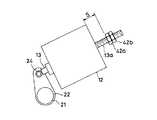
図5は本発明の第2の実施形態の要部を示す側面図である。同図において、40はねじ部40aを備えた作動片で、ねじ部40aが布巻取り用アクチュエータ12の作動ロッド13の先端に螺合し、ナット41によって固定されている。このような構成において、布巻取りレバー22の回動による洗浄布の巻取り量を変えるには、ナット41を緩めねじ部40aとの螺合量を変えて、作動片40を進退させることにより作動片40の突出量Lを変え、布巻取りレバー22のピン24に対する作動片40の遠近方向への移動量を調節することにより行う。
なお、この第2の実施の形態においては、上述した第1の実施例と同様に、洗浄布17を巻取るのに、洗浄布巻取りロール21を搭載した洗浄ユニット15を待避位置と洗浄位置とに移動させて行うだけでなく、洗浄ユニット15を停止させた状態で、布巻取り用アクチュエータ12を作動させて作動ロッド13を進退させて巻取るようにしてもよい。そして、その場合には洗浄ユニット15全体を移動させることがないので、洗浄布17の巻取り動作に係る構造が簡易となる。
【0018】
図6は本発明の第3の実施の形態の要部を示す側面図である。この第3の実施の形態では、作動ロッド13の後端部をアクチュエータ12本体から突出させ、ねじ部13aを形成したものである。42a,42bはねじ部13aに螺合し作動ロッド13の突出量Lを設定して固定するためのダブルナットである。このような構成において、布巻取りレバー22の回動による洗浄布の巻取り量を変えるには、まずナット42bを緩め、次にナット42aを緩めねじ部13aとの螺合量を変えて、作動ロッド13を矢印E方向に移動させることにより作動ロッド13の突出量Lを変え、布巻取りレバー22のピン24に対する作動ロッド13の先端を遠近方向に移動調節することにより行う。
【0019】
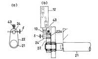
図7は本発明の第4の実施の形態の要部を示し、(a)はレバーの正面図、(b)は一部を破断して示す側面図である。この第4の実施の形態では、ピン24が布巻取りレバー22の軸受孔22aに距離δ分偏心して支承されており、ボルト43を締め付けることによりピン24は軸受孔22a内での周り止めがなされ布巻取りレバー22に固定される。このような構造において、布巻取りレバー22の回動による洗浄布の巻取り量を変えるには、ボルト43を緩めピン24を回動させることによって、布巻取り用のアクチュエータ12の作動ロッド13の先端に対するピン24の周面までの間隔を調節することにより行う。調節が終了したらボルト43を締め付ける。
なお、この第4の実施の形態においては、上述した第1の実施例と同様に、洗浄布17を巻取るのに、洗浄布巻取りロール21を搭載した洗浄ユニット15を待避位置と洗浄位置とに移動させて行うだけでなく、洗浄ユニット15を停止させた状態で、布巻取り用アクチュエータ12を作動させて作動ロッド13を進退させて巻取るようにしてもよい。
【0020】
図8は本発明の第5の実施の形態を示す要部の正面図である。同図において、44は補助レバーであって、その中央部が布巻取りレバー22の上端部に植設されたピン45によって回動自在に支持されている。補助レバー44の下端部にはねじ46が挿通されており、布巻取りレバー22にはこのねじ46が挿通され、ピン45を中心として円弧状に形成された案内溝22bが穿設されており、ねじ46には図示を省略したナットが螺合している。このような構造において、布巻取りレバー22の回動による洗浄布の巻取り量を変えるには、ねじ46のナットを緩め、補助レバー44を、ピン45を回動中心として案内溝22bに沿って回動させることによって、補助レバー44の上端部と図示を省略した布巻取り用のアクチュエータの作動ロッドとの間隔を調節することにより行う。調節が終了したらナットをねじ46に締め付ける。
なお、この第5の実施の形態においては、上述した第1の実施例と同様に、洗浄布17を巻取るのに、洗浄布巻取りロール21を搭載した洗浄ユニット15を待避位置と洗浄位置とに移動させて行うだけでなく、洗浄ユニット15を停止させた状態で、布巻取り用アクチュエータ12を作動させて作動ロッド13を進退させて巻取るようにしてもよい。
【0021】
図9は本発明の第6の実施の形態を示す概略の構成図である。同図において、47は布巻取りレバー22の上端部に枢着されたころである。48は回転中心48aから各頂点までの距離α,β,γがそれぞれ異なる(α≠β≠γ)不等辺三角形状に形成された調整用カムであって、各頂点が前記ころ47に選択的に対接されるように図示を省略したクリック機構により回動角を選択可能に支承されている。このような構成において、布巻取りレバー22の回動による洗浄布の巻取り量を変えるには、作動カム48を回動操作して、ころ47に対接する作動カム48の頂点を選択することによって行われる。
【0022】
図10は本発明の第7の実施の形態を示し、(a)は概略構成を示す側面図、(b)はブロック図である。これらの図において、50は作動ロッド13が布巻取り用のアクチュエータ12内に最も後退したときの原点位置を検出する原点センサ、51は作動ロッド13が原点センサ50で検出された位置から進出した量を検出する位置検出センサである。52は印刷機の各機構を制御する制御装置、53は洗浄布の巻取り量のデータを制御装置52に入力するデータ入力手段、54は布巻取り用のアクチュエータを作動させ作動ロッド13を5段階の進退量で進退させる5ポートソレノイドバルブである。
【0023】
次に、このような印刷機のシリンダ洗浄装置における洗浄布の巻取り量を変える方法を説明する。まず、作動ロッド13が原点位置に位置していることを原点センサ50により確認して制御装置52にそのデータを入力する。データ入力手段53から洗浄布の巻取り量のデータを制御装置52に入力する。そのデータに基づいて制御装置52では作動ロッド13の前進量を計算して、5ポートソレノイドバルブ54にその作動ロッド13の前進量に見合った制御信号を送る。5ポートソレノイドバルブ54の作動により、前進した作動ロッド13の前進量を位置検出センサ51で検出して、そのデータが制御装置52に送られ、制御装置では、上述したデータ入力手段53による入力データと比較する。
このようにして、布巻取りレバー22のピン24に対して作動ロッド13の位置が洗浄布の巻取り量のデータから自動的に遠近移動調節されるので、布巻取りレバー22の回動による洗浄布の巻取り量を正確でかつ迅速に行うことができる。
【0024】
図11は本発明の第8の実施の形態を示す概略構成を示す側面図である。同図に示す実施の形態は、上述した図5に示す実施の形態と同等の構成を有しており、図6に示す実施の形態と異なる点は、洗浄ユニット(図示せず)を洗浄位置と退避位置との間を移動させるときに洗浄布を巻取る構造とせず、洗浄位置または退避位置に固定した状態としておいて洗浄布を巻取る構造とした点と、アクチュエータ12が布巻取り用として作動し作動ロッド13が進退する点である。
【0025】
このような構成において、ナット42a,42bとを緩めてナット42aとアクチュエータ12の後端面と間に間隔Sを形成する。アクチュエータ12を作動させて作動ロッド13を前進させると、ナット42aがアクチュエータ12の後端面に係止するまで作動ロッド13はストロークSだけ前進して、布巻取りレバー22を図中反時計方向に回動させて洗浄布を洗浄布巻取りロール21に巻取る。ここで、洗浄布の巻取り量を変えるには、ナット42a,42bを緩めて間隔Sを変えて、作動ロッド13の前進量を変えることにより行う。
なお、布巻取り用のアクチュエータ12は、布巻取りレバー22を搭載している洗浄ユニット(図示せず)に搭載してもよく、この場合にはアクチュエータ12と布巻取りレバー22との相対位置関係が常に一定となる。
【0026】
図12は本発明の第9の実施の形態を示す概略構成を示す側面図である。同図において、作動ロッド13の先端部にはねじ部13aが形成されており、このねじ部13aにラック55が螺合してナット55aによってラック55は作動ロッド13に取り付けられている。56は布巻取り軸19と同軸上で一方向クラッチ23を介して連結されたピンオンで、ラック55と噛合している。この実施の形態でも、布巻取り用のアクチュエータ12は、布巻取り軸19を搭載している洗浄ユニット(図示を省略)に搭載されている。
【0027】
このような構成において、洗浄布の巻取り動作を説明すると、布巻取り用のアクチュエータ12を作動させて作動ロッド13を進退させる。作動ロッド13は、予め設定された洗浄布の巻取り量のデータに基づき、原点センサ50によって原点位置を検出され、位置検出センサ51によって移動量が検出されて停止し、その進退量Lが決められる。作動ロッド13の進退により、ラック55が図中矢印F方向に往復移動し、ラック55と噛合しているピニオン56が時計および反時計方向に回転する。布巻取り軸19は、ピニオン56が反時計方向に回転するときに、一方向クラッチ23を介してピニオン56と一体的に回転して洗浄布を図示を省略した布巻取りロールに巻取る。このときの洗浄布の巻取り量は、ラック55の移動量L、すなわち作動ロッド13の進退量に等しい。ピニオン56が時計方向に回転するときには、一方向クラッチ23により回転が伝達されず、布巻取り軸19は回転せずに停止する。ここで、洗浄布の巻取り量を変えるには、洗浄布の巻取り量のデータを変更し、この変更したデータに基づき、位置検出センサ51が作動ロッド13の変更した移動量を検出し、作動ロッド13を停止させて移動量Lを変えることにより行われる。
【0028】
図13は本発明の第10の実施の形態を示すブロック図である。同図において、52は制御装置、53はデータ入力手段、58は図示を省略した布巻取り用アクチュエータを作動させる布送りソレノイドバルブ、59は布巻取り用アクチュエータの作動回数を計数する布送り回数カウンタである。このような構成において、データ入力手段53から洗浄布の巻取り量のデータを制御装置52に入力すると、制御装置52では、このデータに基づき布巻取り用アクチュエータの作動回数を設定し、布送りソレノイドバルブ58に制御信号を送出する。布送りソレノイドバルブ58は設定された回数作動して、布巻取り用アクチュエータ59を作動させて洗浄布を巻取る。布送りソレノイドバルブ58の作動回数は布送り回数カウンタ59により計数される。洗浄布の巻取り量を変えるには、データ入力手段53から制御装置52に変更のデータを入力することにより、制御装置52から布送りソレノイドバルブ58に作動回数を変更した制御信号が送出されることにより行われる。
【0029】
図14は本発明の第11の実施の形態を示し、(a)は要部の側面図、(b)は一部を破断して示す正面図である。同図において、60は布巻取りレバー22の先端に枢着されたころ、61はころ60が対接するひし形状に形成されプーリ61aが一体に形成された駆動カムであって、サブフレーム10に植設された支軸61bに回転自在に支持されている。布巻取りレバー22は図示を省略したばね部材によって図中時計方向、すなわちころ60が駆動カム61に対接するように付勢されている。62は前記プーリ61aとモータ64のモータ軸に軸着されたプーリ63との間に張架されたベルトである。
【0030】
このような構成において、モータ64を駆動すると、モータ64の回転は、プーリ63、ベルト62を介してプーリ61aに伝達され、駆動カム61が回転する。駆動カム61が回転することによって、駆動カム61に対接するころ60を介して、布巻取りレバー22が時計、反時計方向に複数回揺動して、一方向クラッチ23を介して連結された洗浄布巻取りロール21を反時計方向に回転させて洗浄布17を巻取る。ここで、洗浄布の巻取り量を変えるには、モータ64の回転の設定回数を変え、駆動カム61の回転数を変えることにより、布巻取りレバー22の時計、反時計方向の揺動数を変えることにより行う。
【0031】
図15は本発明の第12の実施の形態を示し、(a)は概略の構成を示す側面図、(b)は一部を破断した正面図、(c)はブロック図である。同図において、65はエンコーダ66を内蔵したモータであって、このモータ65のモータ軸には、洗浄布巻取りロール21の側面に一体に形成されたギア21aに噛合するギア65aが軸着されている。このような構成において、データ入力手段53から洗浄布の巻取り量のデータを制御装置52に入力すると、制御装置52では、このデータに基づいてモータ65の回転数を設定するとともに、モータ65を駆動する制御信号を送出する。モータ65の回転はギア65aおよびギア21aを介して洗浄布巻取りロール21に伝達され、洗浄布17が巻き取られる。モータ65の回転数はエンコーダ66から制御装置52に入力され、制御装置52ではこの回転数と上述した設定回転数とを比較して、一致したらモータ65に駆動を停止する制御信号を送出する。ここで、洗浄布17の巻取り量を変えるには、データ入力手段からの洗浄布の巻取り量のデータを変えることにより行うことができる。
【0032】
図16は本発明の第13の実施の形態を示す概略構成図である。同図において、68は図15におけるエンコーダ66に代わる洗浄布供給ロール18に近接して配置した変位センサであって、洗浄布供給ロール18の径の大きさを検出するものである。モータ65の回転によって布巻取りロール21が回転し、洗浄布17は布巻取りロール21に巻き取られ、洗浄布供給ロール18の径が漸次小さくなる。変位センサ68で洗浄布供給ロール18の径の変化を検出し、制御装置52では、検出した径の変化を洗浄布の巻取り量に変換し、予め設定した洗浄布の巻取り量と一致したら、モータ65を停止させて洗浄布の巻取りを停止する。巻取り量を変えるには、入力データとしての洗浄布の巻取り量の設定を変えることにより行う。
【0033】
図17は本発明の第14の実施の形態を示す概略構成図である。同図において、69は図15におけるエンコーダ66に代わる巻き取られる洗浄布17に近接して配置した送り量測定センサであって、洗浄布17の移動量を測定するものである。モータ65の回転によって布巻取りロール21が回転し、洗浄布17は布巻取りロール21に巻き取られ、その巻取り量は洗浄布17の移動量を移動量測定センサ69によって測定される。制御装置52では、測定された洗浄布17の移動量と予め設定した洗浄布の巻取り量とが一致したら、モータ65を停止させて洗浄布の巻取りを停止する。巻取り量を変えるには、入力データとしての洗浄布の巻取り量の設定を変えることにより行う。
【0034】
なお、本実施の形態では、洗浄するシリンダとしてブランケット胴2の例に挙げたが、これに限定されず、版胴,渡し胴等の印刷胴や、着ローラ,振りローラ等のローラ等、洗浄が必要なすべてのシリンダに適用できることは勿論である。また、本実施の形態では、シリンダを洗浄する際、洗浄ウェブに洗浄液を吹き付ける構造としたが、シリンダの周面に洗浄液を吹き付けてから洗浄ウェブで拭き取るようにしてもよく、また予め洗浄液が湿らされている洗浄ウェブで拭き取るようにしても上述した同様の作用効果が得られることはいうまでないことである。
また、洗浄ウェブとして布を用いるようにしたが、これに限定されず紙、フィルム等でもよいことは勿論である。
さらに、洗浄布17の供給部として、洗浄布巻取りロール18を用いたが、例えば洗浄布17を折り畳むようにして堆積状に収納した供給部としてもよく、種々の設計変更が可能である。
【0035】
【発明の効果】
請求項1に係る発明によれば、洗浄ユニットの一方向の移動位置における作動部材と巻取りレバーとの離間間隔を遠近調節自在とし、これにより洗浄ユニットの他方向の移動位置における巻取りレバーの作動部材により回動される端限を調節して定量送り手段による洗浄ウェブの一定の巻取り量を調整するようにしたことにより、洗浄ウェブの巻取り量が調節され、このため、汚れた洗浄ウェブの巻取り量が不足して洗浄不良が発生するようなことがない。また、必要以上に巻取り過ぎるようなことがなく経済的である。
【0036】
また、請求項2に係る発明によれば、アクチュエータの作動ロッドは後退することにより巻取りレバーと離間し前進することにより巻取りレバーに当接し巻取りレバーを回動させ、作動ロッドと巻取りレバーとの離間間隔を遠近調節自在とし、定量送り手段による洗浄ウェブの一定の巻取り量を調整するようにしたことにより、遠近調節した後は作動ロッドのみを進退させるだけで洗浄ウェブの一定の巻取り量が調節されるので、簡単な構造にもかかわらず洗浄ウェブの巻取り不足や巻取り過ぎを防止できる。
【図面の簡単な説明】
【図1】本発明に係る印刷機のシリンダ洗浄装置の側面図である。
【図2】本発明に係る印刷機のシリンダ洗浄装置の一部を破断して示す正面図である。
【図3】本発明に係る印刷機のシリンダ洗浄装置における動作を説明するための側面図である。
【図4】本発明に係る印刷機のシリンダ洗浄装置における動作を説明するための側面図である。
【図5】本発明に係る印刷機のシリンダ洗浄装置の第2の実施の形態の要部を示す側面図である。
【図6】本発明に係る印刷機のシリンダ洗浄装置の第3の実施の形態の要部を示す側面図である。
【図7】本発明に係る印刷機のシリンダ洗浄装置の第4の実施の形態を示し、(a)は要部の正面図、(b)は一部を破断した側面図である。
【図8】本発明に係る印刷機のシリンダ洗浄装置の第5の実施の形態の要部を示す正面図である。
【図9】本発明に係る印刷機のシリンダ洗浄装置の第6の実施の形態の概略を示す構成図である。
【図10】本発明に係る印刷機のシリンダ洗浄装置の第7の実施の形態を示し、(a)は概略の側面図、(b)はブロック図である。
【図11】本発明に係る印刷機のシリンダ洗浄装置の第8の実施の形態を示す概略の側面図である。
【図12】本発明に係る印刷機のシリンダ洗浄装置の第9の実施の形態を示す概略の側面図である。
【図13】本発明に係る印刷機のシリンダ洗浄装置の第10の実施の形態を示すブロック図である。
【図14】本発明に係る印刷機のシリンダ洗浄装置の第11の実施の形態を示し、(a)は要部の正面図、(b)は一部を破断した側面図である。
【図15】本発明に係る印刷機のシリンダ洗浄装置の第12の実施の形態を示し、(a)は要部の正面図、(b)は一部を破断した側面図、(c)はブロック図である。
【図16】本発明に係る印刷機のシリンダ洗浄装置の第13の実施の形態を示す概略の側面図である。
【図17】本発明に係る印刷機のシリンダ洗浄装置の第14の実施の形態を示す概略の側面図である。
【図18】従来の印刷機のシリンダ洗浄装置の側面図である。
【図19】従来の印刷機のシリンダ洗浄装置の一部を破断した正面図である。
【符号の説明】
2…ブランケット胴、4…ユニット着脱用のアクチュエータ、12…布巻取り用のアクチュエータ、15…洗浄ユニット、17…洗浄布、18…洗浄布供給ロール、19…布巻取り軸、21…洗浄布巻取りロール、22…巻取りレバー、24…ピン、27…定量送り手段、29…定量送りカム、35…作動部材、40…作動片、44…補助レバー、48…作動カム、50…原点センサ、51…位置センサ、52…制御装置、53…データ入力手段、55…ラック、56…ピニオン、61…駆動カム、65…モータ、66…エンコーダ、68…変位センサ、69…移動量測定センサ。[0001]
TECHNICAL FIELD OF THE INVENTION
The present invention relates to a cylinder cleaning device for cleaning a printing cylinder such as a plate cylinder, a blanket cylinder, an impression cylinder, and a transfer cylinder, and a peripheral surface of a cylinder such as a setting roller and a swing roller in various printing presses.
[0002]
[Prior art]
2. Description of the Related Art Various printing presses such as offset printing presses and intaglio printing presses have printing cylinders such as plate cylinders, blanket cylinders, impression cylinders, transfer cylinders, and rollers such as landing rollers and swing rollers. Since foreign matter such as ink residue and paper dust adheres to the peripheral surface of the cylinder during printing work and degrades the quality of printed matter, the printing press is provided with a cylinder cleaning device for removing these foreign matter. The cylinder cleaning apparatus includes a cleaning unit provided with a supply roller that supplies a belt-shaped cleaning web made of a nonwoven fabric or the like to which a cleaning liquid is supplied and wipes off foreign substances attached to a cylinder peripheral surface, and a winding roller that winds the cleaning web, An actuator for winding the cleaning web that winds the cleaning web by rotating the take-up roller, and moving the cleaning unit in the direction of the distance to and from the peripheral surface of the cylinder to contact or separate the cleaning web from the peripheral surface of the cylinder. And an actuator for attaching and detaching the unit. The cylinder cleaning device is provided with a constant-rate feeding unit that winds a fixed amount of the cleaning web regardless of the amount of the cleaning web wound on the winding roller.
[0003]
FIG. 18 is a side view of a conventional cylinder cleaning device of a printing press, and FIG. 19 is a developed view of the same viewed from the front. In these figures,
[0004]
The cleaning unit indicated by
[0005]
The cloth take-
[0006]
A
[0007]
Next, the cleaning operation in such a configuration will be described. The cleaning liquid is jetted onto the cleaning
[0008]
To take up the
[0009]
[Problems to be solved by the invention]
As the pressing force for pressing the cleaning cloth against the peripheral surface of the
[0010]
Accordingly, the present invention has been made in view of the above-described conventional problems, and an object of the present invention is to provide a cylinder cleaning apparatus for a printing press that can prevent a cleaning defect and economically use a cleaning web. It is in.
[0011]
[Means for Solving the Problems]
In order to achieve this object, the invention according to claim 1 includes a winding roll for winding a cleaning web from a supply unit, a winding lever for rotating the winding roll, and a rotating end of the winding lever. A cleaning unit provided with a fixed-quantity feeding means for winding a fixed amount of the cleaning web regardless of the amount of the cleaning web wound on the take-up roll. Contact the peripheral surface ofWashing Position and distance from the peripheral surface of the cylinderEvacuation A cylinder cleaning device for a printing press supported on a printing press frame so as to be movable between positions, comprising an operating member supported on the printing press frame and in contact with the take-up lever, andEither the cleaning position or the retreat position In the above, the winding lever is separated from the operating member and comes into contact with the fixed amount feeding means, whereby the rotation end of the winding lever is regulated, andMove to the other position of the washing position or the retreat position As a result, the winding lever comes into contact with the operating member and rotates, and the cleaning unit is rotated.The one position The distance between the actuating member and the take-up lever in the distance can be freely adjusted, whereby the cleaning unitThe other position And adjusting the fixed amount by adjusting an end of the winding lever that is rotated by the operating member.
Further, the invention according to
[0012]
BEST MODE FOR CARRYING OUT THE INVENTION
Hereinafter, embodiments of the present invention will be described with reference to the drawings. FIG. 1 is a side view of a cylinder cleaning device for a printing press according to the present invention, FIG. 2 is an exploded front view of the same, and FIG. 3 and FIG. In these drawings, the same or equivalent members described in the prior art shown in FIGS. 18 and 19 described above are denoted by the same reference numerals, and detailed description thereof will be omitted. The feature of the present invention is that a
[0013]
That is, the
[0014]
Next, the operation of winding the cleaning cloth in the cylinder cleaning device of the printing press having such a configuration will be described. First, the
[0015]
Thereafter, when the
[0016]
Here, in order to change the winding amount of the cleaning
[0017]
FIG. 5 is a side view showing a main part of the second embodiment of the present invention. In the figure,
In the second embodiment, as in the first embodiment, the
[0018]
FIG. 6 is a side view showing a main part of the third embodiment of the present invention. In the third embodiment, the rear end of the operating
[0019]
7A and 7B show a main part of a fourth embodiment of the present invention, wherein FIG. 7A is a front view of a lever, and FIG. 7B is a side view with a part cut away. In the fourth embodiment, the
In the fourth embodiment, the
[0020]
FIG. 8 is a front view of a main part showing a fifth embodiment of the present invention. In the figure,
In the fifth embodiment, as in the first embodiment described above, the
[0021]
FIG. 9 is a schematic configuration diagram showing a sixth embodiment of the present invention. In the figure,
[0022]
FIG. 10 shows a seventh embodiment of the present invention, in which (a) is a side view showing a schematic configuration, and (b) is a block diagram. In these figures,
[0023]
Next, a method of changing the winding amount of the cleaning cloth in the cylinder cleaning device of the printing press will be described. First, the
In this manner, the position of the operating
[0024]
FIG. 11 is a side view showing a schematic configuration showing an eighth embodiment of the present invention. The embodiment shown in the figure has the same configuration as the embodiment shown in FIG. 5 described above, and differs from the embodiment shown in FIG. 6 in that a cleaning unit (not shown) is placed in a cleaning position. The structure in which the cleaning cloth is wound when the cleaning cloth is wound at the cleaning position or the retracted position is not used when moving between the cleaning position and the retracting position. This is the point where the operation is performed and the
[0025]
In such a configuration, the nuts 42 a and 42 b are loosened to form a gap S between the
The
[0026]
FIG. 12 is a side view showing a schematic configuration showing a ninth embodiment of the present invention. In the figure, a
[0027]
In such a configuration, the operation of winding the cleaning cloth will be described. The
[0028]
FIG. 13 is a block diagram showing a tenth embodiment of the present invention. In the figure, 52 is a control device, 53 is data input means, 58 is a cloth feeding solenoid valve for activating a cloth winding actuator not shown, and 59 is a cloth feeding number counter for counting the number of times the cloth winding actuator is operated. is there. In such a configuration, when data on the amount of cleaning cloth to be wound is input from the data input means 53 to the
[0029]
14A and 14B show an eleventh embodiment of the present invention, wherein FIG. 14A is a side view of a main part, and FIG. In the drawing,
[0030]
In such a configuration, when the
[0031]
15A and 15B show a twelfth embodiment of the present invention, wherein FIG. 15A is a side view showing a schematic configuration, FIG. 15B is a partially cutaway front view, and FIG. 15C is a block diagram. In the figure,
[0032]
FIG. 16 is a schematic configuration diagram showing a thirteenth embodiment of the present invention. In the figure,
[0033]
FIG. 17 is a schematic configuration diagram showing a fourteenth embodiment of the present invention. In the figure,
[0034]
In the present embodiment, the
In addition, although the cloth is used as the cleaning web, it is needless to say that the cloth is not limited to this, but may be paper, film, or the like.
Further, the cleaning cloth take-
[0035]
【The invention's effect】
According to the first aspect of the present invention, the distance between the operating member and the take-up lever at the one-way movement position of the cleaning unit can be adjusted in perspective, whereby the take-up lever at the movement position of the cleaning unit in the other direction can be adjusted. The constant amount of the cleaning web wound by the constant-rate feeding means is adjusted by adjusting the end rotated by the operating member. By doing so, the winding amount of the cleaning web is adjusted, and therefore, there is no possibility that the winding amount of the dirty cleaning web becomes insufficient and cleaning failure occurs. In addition, it is economical without excessive winding.
[0036]
According to the second aspect of the present invention,The actuator rod of the actuator retracts and separates from the take-up lever, and moves forward to contact the take-up lever and rotate the take-up lever. Adjusting the constant winding amount of the cleaning web by the feeding means After adjusting the perspective,Move the operating rod only Just let the cleaning webFixed Since the winding amount is adjusted, it is possible to prevent insufficient or excessive winding of the cleaning web despite the simple structure.
[Brief description of the drawings]
FIG. 1 is a side view of a cylinder cleaning device for a printing press according to the present invention.
FIG. 2 is a partially cutaway front view of the cylinder cleaning device of the printing press according to the present invention.
FIG. 3 is a side view for explaining the operation of the cylinder cleaning device of the printing press according to the present invention.
FIG. 4 is a side view for explaining the operation of the cylinder cleaning device of the printing press according to the present invention.
FIG. 5 is a side view showing a main part of a second embodiment of the cylinder cleaning device for a printing press according to the present invention.
FIG. 6 is a side view showing a main part of a third embodiment of the cylinder cleaning device for a printing press according to the present invention.
FIGS. 7A and 7B show a fourth embodiment of a cylinder cleaning device for a printing press according to the present invention, wherein FIG. 7A is a front view of a main part, and FIG.
FIG. 8 is a front view showing a main part of a fifth embodiment of a cylinder cleaning device for a printing press according to the present invention.
FIG. 9 is a configuration diagram schematically showing a sixth embodiment of a cylinder cleaning device for a printing press according to the present invention.
10A and 10B show a seventh embodiment of a cylinder cleaning device for a printing press according to the present invention, wherein FIG. 10A is a schematic side view and FIG. 10B is a block diagram.
FIG. 11 is a schematic side view showing an eighth embodiment of a cylinder cleaning device for a printing press according to the present invention.
FIG. 12 is a schematic side view showing a ninth embodiment of a cylinder cleaning device for a printing press according to the present invention.
FIG. 13 is a block diagram illustrating a cylinder cleaning device for a printing press according to a tenth embodiment of the present invention.
14A and 14B show an eleventh embodiment of a cylinder cleaning device for a printing press according to the present invention, wherein FIG. 14A is a front view of a main part, and FIG.
15A and 15B show a twelfth embodiment of a cylinder cleaning device for a printing press according to the present invention, wherein FIG. 15A is a front view of a main part, FIG. 15B is a partially cutaway side view, and FIG. It is a block diagram.
FIG. 16 is a schematic side view showing a thirteenth embodiment of a cylinder cleaning device for a printing press according to the present invention.
FIG. 17 is a schematic side view showing a fourteenth embodiment of a cylinder cleaning device for a printing press according to the present invention.
FIG. 18 is a side view of a conventional cylinder cleaning device of a printing press.
FIG. 19 is a front view in which a part of a conventional cylinder cleaning device of a printing press is cut away.
[Explanation of symbols]
2 ... blanket cylinder, 4 ... actuator for attaching / detaching unit, 12 ... actuator for winding cloth, 15 ... cleaning unit, 17 ... cleaning cloth, 18 ... cleaning cloth supply roll, 19 ... cloth winding shaft, 21 ... cleaning cloth winding roll , 22 ... take-up lever, 24 ... pin, 27 ... fixed amount feeding means, 29 ... fixed amount feeding cam, 35 ... operating member, 40 ... operating piece, 44 ... auxiliary lever, 48 ... operating cam, 50 ... origin sensor, 51 ... Position sensor, 52 ... Control device, 53 ... Data input means, 55 ... Rack, 56 ... Pinion, 61 ... Drive cam, 65 ... Motor, 66 ... Encoder, 68 ... Displacement sensor, 69 ... Movement amount measuring sensor.
Claims (2)
Translated fromJapanese印刷機フレーム側に支持され前記巻取りレバーと当接する作動部材を備え、
前記洗浄ユニットの前記洗浄位置または前記退避位置のいずれか一方の位置において前記巻取りレバーは前記作動部材と離間するとともに前記定量送り手段と接触して前記巻取りレバーの回動端限が規制され、前記洗浄ユニットの前記洗浄位置または前記退避位置のいずれか他方の位置への移動により前記巻取りレバーが前記作動部材と当接して回動し、
前記洗浄ユニットの前記一方の位置における前記作動部材と前記巻取りレバーとの離間間隔を遠近調節自在とし、これにより前記洗浄ユニットの前記他方の位置における前記巻取りレバーの前記作動部材により回動される端限を調節して前記一定量を調整することを特徴とする印刷機のシリンダ洗浄装置。A take-up roll that takes up the cleaning web from the supply unit; a take-up lever that rotates the take-up roll; and an amount of the cleaning web that is restricted by the end of rotation of the take-up lever and is taken up by the take-up roll. A cleaning unit provided with fixed amount feeding means for winding a fixed amount of the cleaning web regardless of the cleaning unit, the cleaning unit being separated from the peripheral surface of the cylinder by acleaning position where the cleaning web is brought into contact with the peripheral surface of the cylinder. In the cylinder cleaning device of the printing press supported on the printing press frame side so as to be movable between theretracted position to be moved,
An operating member supported on the printing press frame side and in contact with the winding lever,
In one of thecleaning position and the retracted position of the cleaning unit, the take-up lever is separated from the operating member, and is in contact with the fixed-quantity feeding means, whereby the rotation end of the take-up lever is regulated.Movement of the cleaning unitto the other of the cleaning position or the retracted position causes the winding lever to rotate in contact with the operating member,
The separation distance between the actuating member and the winding lever inthe one position of the cleaning unit and freely accommodation, is thereby rotated by the actuating member of the winding lever inthe other position of the cleaning unit A cylinder cleaning device for a printing press, wherein the fixed amount is adjusted by adjusting an end limit.
進退自在な作動ロッドを有するアクチュエータを備え、作動ロッドは後退することにより前記巻取りレバーと離間し前進することにより前記巻取りレバーに当接し巻取りレバーを回動させ、
前記作動ロッドと前記巻取りレバーとの離間間隔を遠近調節自在とし、前記定量送り手段による洗浄ウェブの一定の巻取り量を調整することを特徴とする印刷機のシリンダ洗浄装置。A take-up roll that takes up the cleaning web from the supply unit, a take-up lever that rotates the take-up roll, and a predetermined amount of cleaning web that is taken up regardless of the amount of the cleaning web that is taken up by the take-up roll In a cylinder cleaning device of a printing press, comprising a fixed amount feeding means and cleaning the cylinder surface by contacting the cleaning web with the cylinder surface,
An actuator having an operating rod that is movable forward and backward, the operating rod is separated from the winding lever by retreating and abuts on the winding lever by moving forward to rotate the winding lever ,
A cylinder cleaning device for a printing press, wherein a distance between the operating rod and the take-up lever is adjustable so that the distance between the operation rod and the take-up lever can beadjusted .
Priority Applications (5)
| Application Number | Priority Date | Filing Date | Title |
|---|---|---|---|
| JP19020295AJP3604785B2 (en) | 1995-07-26 | 1995-07-26 | Printing machine cylinder cleaning device |
| US08/683,713US5758577A (en) | 1995-07-26 | 1996-07-18 | Cylinder cleaning apparatus for printing press |
| EP96250163AEP0755789B1 (en) | 1995-07-26 | 1996-07-23 | Cylinder cleaning apparatus for a printing press |
| AT96250163TATE193679T1 (en) | 1995-07-26 | 1996-07-23 | DEVICE FOR CLEANING A CYLINDER FOR A PRINTING MACHINE |
| DE69608741TDE69608741T2 (en) | 1995-07-26 | 1996-07-23 | Device for cleaning a cylinder for a printing press |
Applications Claiming Priority (1)
| Application Number | Priority Date | Filing Date | Title |
|---|---|---|---|
| JP19020295AJP3604785B2 (en) | 1995-07-26 | 1995-07-26 | Printing machine cylinder cleaning device |
Publications (2)
| Publication Number | Publication Date |
|---|---|
| JPH0939215A JPH0939215A (en) | 1997-02-10 |
| JP3604785B2true JP3604785B2 (en) | 2004-12-22 |
Family
ID=16254163
Family Applications (1)
| Application Number | Title | Priority Date | Filing Date |
|---|---|---|---|
| JP19020295AExpired - Fee RelatedJP3604785B2 (en) | 1995-07-26 | 1995-07-26 | Printing machine cylinder cleaning device |
Country Status (5)
| Country | Link |
|---|---|
| US (1) | US5758577A (en) |
| EP (1) | EP0755789B1 (en) |
| JP (1) | JP3604785B2 (en) |
| AT (1) | ATE193679T1 (en) |
| DE (1) | DE69608741T2 (en) |
Families Citing this family (23)
| Publication number | Priority date | Publication date | Assignee | Title |
|---|---|---|---|---|
| US8069407B1 (en) | 1998-12-08 | 2011-11-29 | Yodlee.Com, Inc. | Method and apparatus for detecting changes in websites and reporting results to web developers for navigation template repair purposes |
| US7085997B1 (en) | 1998-12-08 | 2006-08-01 | Yodlee.Com | Network-based bookmark management and web-summary system |
| US7672879B1 (en) | 1998-12-08 | 2010-03-02 | Yodlee.Com, Inc. | Interactive activity interface for managing personal data and performing transactions over a data packet network |
| US7752535B2 (en) | 1999-06-01 | 2010-07-06 | Yodlec.com, Inc. | Categorization of summarized information |
| DE10044861B4 (en)* | 1999-09-29 | 2010-09-02 | Heidelberger Druckmaschinen Ag | Winding method and apparatus for printing material processing machines |
| DE10000554A1 (en)* | 2000-01-08 | 2001-07-12 | Baldwin Grafotec Gmbh | Washing machine for printing press cylinders |
| JP2001322254A (en) | 2000-05-17 | 2001-11-20 | Komori Corp | Printing press and control method for the printing press |
| JP2001322250A (en) | 2000-05-17 | 2001-11-20 | Komori Corp | Printing press and control method for the printing press |
| ATE365635T1 (en)* | 2003-05-14 | 2007-07-15 | Kba Giori Sa | DEVICE AND METHOD FOR CLEANING A CYLINDER OR ROLLER OF A PRINTING MACHINE |
| US7011025B2 (en)* | 2003-06-04 | 2006-03-14 | Egan Ronald G | Flexographic printing plate cleaner |
| US7270057B2 (en)* | 2004-01-28 | 2007-09-18 | Rdp Marathon Inc. | Rolling element adjustment system |
| US7606752B2 (en) | 2006-09-07 | 2009-10-20 | Yodlee Inc. | Host exchange in bill paying services |
| DE102006041894A1 (en) | 2006-09-07 | 2008-03-27 | Baldwin Germany Gmbh | Cloth feed control device of a cleaning device for printing press cylinder |
| US8220389B2 (en)* | 2007-12-12 | 2012-07-17 | Hewlett-Packard Development Company, L.P. | Tray surface cleaning device |
| DE102009013327B4 (en)* | 2008-04-21 | 2019-03-07 | Heidelberger Druckmaschinen Ag | Method for operating a printing machine |
| US8261334B2 (en) | 2008-04-25 | 2012-09-04 | Yodlee Inc. | System for performing web authentication of a user by proxy |
| US8555359B2 (en) | 2009-02-26 | 2013-10-08 | Yodlee, Inc. | System and methods for automatically accessing a web site on behalf of a client |
| US8590449B2 (en)* | 2009-06-11 | 2013-11-26 | Ronald G. Egan | Dry flexographic printing plate cleaner system and method |
| FI124967B (en) | 2012-04-24 | 2015-04-15 | Tresu As | A cleaning arrangement and method for cleaning a flexographic coating unit |
| US9421757B2 (en) | 2014-10-23 | 2016-08-23 | Ronald G. Egan | Method and apparatus for cleaning printing presses for three dimensional objects |
| US10040101B2 (en)* | 2015-01-23 | 2018-08-07 | The Boeing Company | Robotic surface-cleaning assemblies and methods |
| US11845103B2 (en) | 2021-09-09 | 2023-12-19 | The Boeing Company | Liquid applicators and methods of applying liquid to a substrate using the same |
| DE102023129409A1 (en)* | 2023-10-25 | 2025-04-30 | Koenig & Bauer Ag | Method for operating a cleaning device for cleaning a rotating body and cleaning device for cleaning a rotating body |
Family Cites Families (11)
| Publication number | Priority date | Publication date | Assignee | Title |
|---|---|---|---|---|
| US3084626A (en)* | 1961-01-06 | 1963-04-09 | Anton R Stobb | Apparatus for method for wiping a printing cylinder |
| DE3308980C2 (en)* | 1983-03-14 | 1986-03-13 | Georg Spiess Gmbh, 8906 Gersthofen | Washing device for a blanket cylinder of a printing machine |
| JPH01314173A (en)* | 1988-06-14 | 1989-12-19 | Nippon Baldwin Kk | Automatic cylinder cleaning device |
| JPH0276740A (en)* | 1988-09-13 | 1990-03-16 | Nikka Kk | Blanket cleaning device and cleaning of printer |
| EP0364901B1 (en)* | 1988-10-19 | 1994-04-27 | Dai Nippon Insatsu Kabushiki Kaisha | Cleaning system for offset sheet-fed printing presses |
| DE3909119C2 (en)* | 1989-03-20 | 1997-01-23 | Heidelberger Druckmasch Ag | Washing device for a printing machine |
| JP2900272B2 (en)* | 1989-12-27 | 1999-06-02 | 大日本印刷株式会社 | Offset sheet-fed printing press impression cylinder cleaning device |
| US5325779A (en)* | 1992-01-27 | 1994-07-05 | Komori Corporation | Printing cylinder/roller cleaning apparatus for printing press |
| US5328116A (en)* | 1992-06-12 | 1994-07-12 | Nikka Kabushiki Kaisha | Regulated length take-up device |
| JPH0667031A (en)* | 1992-08-18 | 1994-03-11 | Koudou:Kk | Plane illumination device |
| US5325780A (en)* | 1993-03-09 | 1994-07-05 | Sakurai Graphic Systems | Ink washing device for a printing machine |
- 1995
- 1995-07-26JPJP19020295Apatent/JP3604785B2/ennot_activeExpired - Fee Related
- 1996
- 1996-07-18USUS08/683,713patent/US5758577A/ennot_activeExpired - Fee Related
- 1996-07-23EPEP96250163Apatent/EP0755789B1/ennot_activeExpired - Lifetime
- 1996-07-23ATAT96250163Tpatent/ATE193679T1/ennot_activeIP Right Cessation
- 1996-07-23DEDE69608741Tpatent/DE69608741T2/ennot_activeExpired - Fee Related
Also Published As
| Publication number | Publication date |
|---|---|
| ATE193679T1 (en) | 2000-06-15 |
| US5758577A (en) | 1998-06-02 |
| DE69608741T2 (en) | 2001-02-22 |
| EP0755789B1 (en) | 2000-06-07 |
| DE69608741D1 (en) | 2000-07-13 |
| EP0755789A1 (en) | 1997-01-29 |
| JPH0939215A (en) | 1997-02-10 |
Similar Documents
| Publication | Publication Date | Title |
|---|---|---|
| JP3604785B2 (en) | Printing machine cylinder cleaning device | |
| US5046416A (en) | Printing unit for rotary printing presses | |
| US8245636B2 (en) | Interchangeable doctor blade assembly | |
| JPH04234649A (en) | Moistening device for printing machine | |
| EP0364901B1 (en) | Cleaning system for offset sheet-fed printing presses | |
| JPH07106628B2 (en) | Printing machine with a coater function | |
| JP3655358B2 (en) | Cylinder cleaning device for printing press | |
| JP4652517B2 (en) | Dampening device for lithographic printing machine and lithographic printing machine having this dampening device | |
| WO2014203684A1 (en) | Intaglio printing machine and intaglio printing method | |
| JP2008201120A (en) | Switching processing method and apparatus | |
| US4729312A (en) | Ink duct for offset or letterpress printing machines | |
| JPH0717049B2 (en) | Roller connection / separation device for offset printing machine | |
| JP2594327Y2 (en) | Cleaning equipment for printing press | |
| CN117734296A (en) | Full-automatic non-woven fabric double-color screen printer | |
| JP2703761B2 (en) | Printing machine ink unit | |
| JPH081869Y2 (en) | Cylinder cleaning device for printing machine | |
| JP4455695B2 (en) | Printing device | |
| JP3785213B2 (en) | Inking device of printing machine | |
| JPH0464512B2 (en) | ||
| JP2588224Y2 (en) | Cleaning device for printing cylinders and rollers of printing press | |
| JPH0314354Y2 (en) | ||
| CN221584787U (en) | Double-color screen printer | |
| JP2571050Y2 (en) | Imprinting cylinder cleaning device for printing press | |
| JPH0532290Y2 (en) | ||
| JP2600195Y2 (en) | Cleaning device for printing cylinders and rollers of printing press |
Legal Events
| Date | Code | Title | Description |
|---|---|---|---|
| A131 | Notification of reasons for refusal | Free format text:JAPANESE INTERMEDIATE CODE: A131 Effective date:20040427 | |
| A521 | Request for written amendment filed | Free format text:JAPANESE INTERMEDIATE CODE: A523 Effective date:20040616 | |
| TRDD | Decision of grant or rejection written | ||
| A01 | Written decision to grant a patent or to grant a registration (utility model) | Free format text:JAPANESE INTERMEDIATE CODE: A01 Effective date:20040928 | |
| A61 | First payment of annual fees (during grant procedure) | Free format text:JAPANESE INTERMEDIATE CODE: A61 Effective date:20040930 | |
| R150 | Certificate of patent or registration of utility model | Free format text:JAPANESE INTERMEDIATE CODE: R150 | |
| FPAY | Renewal fee payment (event date is renewal date of database) | Free format text:PAYMENT UNTIL: 20081008 Year of fee payment:4 | |
| FPAY | Renewal fee payment (event date is renewal date of database) | Free format text:PAYMENT UNTIL: 20091008 Year of fee payment:5 | |
| FPAY | Renewal fee payment (event date is renewal date of database) | Free format text:PAYMENT UNTIL: 20091008 Year of fee payment:5 | |
| FPAY | Renewal fee payment (event date is renewal date of database) | Free format text:PAYMENT UNTIL: 20101008 Year of fee payment:6 | |
| FPAY | Renewal fee payment (event date is renewal date of database) | Free format text:PAYMENT UNTIL: 20111008 Year of fee payment:7 | |
| LAPS | Cancellation because of no payment of annual fees |