JP3604380B2 - Data relay method, data relay device, and data relay system using the device - Google Patents
Data relay method, data relay device, and data relay system using the deviceDownload PDFInfo
- Publication number
- JP3604380B2 JP3604380B2JP2003067270AJP2003067270AJP3604380B2JP 3604380 B2JP3604380 B2JP 3604380B2JP 2003067270 AJP2003067270 AJP 2003067270AJP 2003067270 AJP2003067270 AJP 2003067270AJP 3604380 B2JP3604380 B2JP 3604380B2
- Authority
- JP
- Japan
- Prior art keywords
- data relay
- relay device
- router
- logical data
- route
- Prior art date
- Legal status (The legal status is an assumption and is not a legal conclusion. Google has not performed a legal analysis and makes no representation as to the accuracy of the status listed.)
- Expired - Fee Related
Links
Images


Landscapes
- Data Exchanges In Wide-Area Networks (AREA)
Description
Translated fromJapanese【0001】
【発明の属する技術分野】
この発明は、メイン処理とバックアップ処理を行う複数の論理データ中継装置によって構築されて、データを中継するデータ中継方法、データ中継装置およびその装置を用いたデータ中継システムに関し、特に他のデータ中継装置との間で経路情報の交換を行うデータ中継方法、データ中継装置およびその装置を用いたデータ中継システムに関するものである。
【0002】
【従来の技術】
従来のデータ中継方法は、たとえば非特許文献1に示すように、単一の自律システム(AS:Autonomous System)内のルータ間で、OSPF(Open Shortest Path First:RFC2328)のプロトコルを用いて、経路制御のための情報(以下、「経路情報」という)の交換を行うものがあった。なお、このASとは、単一の管理主体によって単一経路制御ポリシーのもとで管理・運用される範囲のことで、たとえばISP(Internet Service Provider:インターネットサービス事業者)がこれに相当する。
【0003】
このデータ中継方法では、図18に示すように、AS内部のネットワーク10上にOSPFのリンクステート型プロトコルを用いた複数のルータ20,30が接続されており、これらルータ20,30がこのネットワーク全体のトポロジーの情報を持っている。これらルータ20,30は、このトポロジー情報に基づいて、最適経路の算出を行っている。
【0004】
また、トポロジーが変化した場合には、ルータ20,30間で経路情報の交換が迅速に行われ、常に最新のトポロジー情報に基づいた最適経路の算出を行っている。この算出された最適経路情報は、経路情報テーブル21c,22c内のフォワーディングテーブル(図示せず)に格納されており、この最適経路情報に基づいて、ルータ20,30間でIP(Internet Protocol)データの中継を行っている。
【0005】
これらルータ20,30は、故障時の安全対策として、OSPFプロトコルの二重化を行う場合がある。この場合には、たとえば図18に示すように、物理的には1つのルータ(以下、「物理ルータ」という)20を、データ中継の動作を行う上で論理的に2つのルータ(以下、「論理ルータ」という)21,22に設定し、この二重化されたOSPFプロトコル(OSPF処理部21b,22bに内蔵)によって、これら論理ルータ21,22が他のルータ30とルーティング制御データ(以下、「経路情報」という)の交換を行うものがある。
【0006】
この論理ルータは、動作がアクティブ状態にあり、メイン処理を行う論理ルータ(以下、「メインルータ」という)21と、動作がスタンバイ状態にあり、バックアップ処理を行う論理ルータ(以下、「バックアップルータ」という)22とからなり、各論理ルータ21,22を他のルータ30と接続させ、他のルータ30から受信した経路情報を即座にコピーして、論理ルータ21,22のOSPF処理部21b,22bに転送していた。また、メインルータ21側で生成したデータに関しては、ルータ21,22でアクティブ状態とスタンバイ状態を切り替えるときに、すぐにバックアップルータ22でアクティブ状態の動作を開始できるように、ルータ21,22間で逐次同期をとる必要がある。
【0007】
【非特許文献1】
John Moy著、“RFC2328 OSPF Version2” [online]、インターネット公式プロトコル(STD1)、1998年4月、p.6−15、AlterNIC The Network Information Center、[平成15年1月22日検索]、インターネット<URL:HYPERLINK”http://www.alternic.org/rfcs/rfc2300/rfc2328.html”>
【0008】
【発明が解決しようとする課題】
しかしながら、上記従来例では、他のルータとの経路情報の交換途中で故障が発生してパケットロスがでると、メインルータとバックアップルータが完全に同期できなくなり、上記の状態切り替え時にトポロジー変化に伴う経路情報の受信が不可能となるので、バックアップルータが初期指定で初期ステートに戻って全体の経路情報を取得するまで、データの中継処理が不可能となり、サービスが停止してしまうという問題点があった。
【0009】
この発明は、上記問題点に鑑みなされたもので、故障発生時にもトポロジー変化に伴う経路情報の受信を正確に行い、データの中継処理を停止させることなく、容易にデータ中継装置の二重化を図ることができるデータ中継方法、データ中継装置およびその装置を用いたデータ中継システムを提供することを目的とする。
【0010】
【課題を解決するための手段】
上記目的を達成するため、請求項1にかかるデータ中継方法では、複数のデータ中継装置が、論理的にアクティブ状態とスタンバイ状態の関係に設定され、それぞれがメイン処理とバックアップ処理を行う少なくとも2つの論理データ中継装置を構築してデータを中継するデータ中継方法において、前記論理データ中継装置のうちのアクティブ状態の第1の論理データ中継装置と経路情報取得用の第1の通信装置が、前記データ中継を行うための経路交換プロトコルを使用して、他のデータ中継装置と経路情報の交換を行うとともに、該交換によって取得された経路情報を前記スタンバイ状態の第2の論理データ中継装置に送出し、前記第1の論理データ中継装置および前記第1の通信装置の少なくとも一つから取り込んだ前記経路情報に基づき、前記第2の論理データ中継装置が最適経路情報を選出することを特徴とするデータ中継方法が提供される。
【0011】
この発明によれば、経路情報の交換プロトコルとしてOSPFを使用するとともに、ルーティング制御処理を二重化して、たとえばIPデータを中継するデータ中継方法にて、アクティブ状態の第1の論理データ中継装置であるメインルータと同様に、第1の通信装置である仮想ルータが隣接する他のデータ中継装置から最新の経路情報を取得して、スタンバイ状態の第2の論理データ中継装置であるバックアップルータで、このメインルータと仮想ルータから取り込んだ経路情報に基づき、最適経路を選出することで、データの中継処理を停止させることなく、容易にデータ中継装置の二重化を図る。
【0012】
また、請求項2にかかるデータ中継方法では、複数のデータ中継装置が、論理的にアクティブ状態とスタンバイ状態の関係に設定され、それぞれがメイン処理とバックアップ処理を行う少なくとも2つの論理データ中継装置を構築してデータを中継するデータ中継方法において、前記論理データ中継装置のうちのアクティブ状態の第1の論理データ中継装置が、前記データ中継を行うための経路交換プロトコルを使用して、他のデータ中継装置と経路情報の交換を行う第1の交換工程と、前記交換された経路情報を前記第1の論理データ中継装置から前記スタンバイ状態の第2の論理データ中継装置に送出する送出工程と、前記第2の論理データ中継装置が、前記第1の論理データ中継装置の故障を監視する故障監視工程と、前記監視結果に基づいて、前記第2の論理データ中継装置が前記バックアップ処理から前記メイン処理に移行する処理移行工程と、経路情報取得用の第1の通信装置が、前記データ中継を行うための経路交換プロトコルを使用して、前記他のデータ中継装置と経路情報の交換を行う第2の交換工程と、前記第1の論理データ中継装置および前記第1の通信装置の少なくとも一つから取り込まれた経路情報に基づいて、前記第2の論理データ中継装置が最適経路情報を選出する第1の経路選出工程とを含むことを特徴とする。
【0013】
この発明によれば、経路情報の交換プロトコルとしてOSPFを使用するとともに、ルーティング制御処理を二重化して、IPデータを中継するデータ中継方法にて、アクティブ状態の論理データ中継装置であるメインルータと同様に、第1の通信装置である仮想ルータが隣接する他のデータ中継装置から最新の経路情報を取得するとともに、スタンバイ状態の論理データ中継装置であるバックアップルータがメインルータの故障を検出してバックアップルータに処理を移行する際に、事前にメインルータと同期させておいた経路情報に基づいてデータ処理を継続しつつ、第1の通信装置である仮想ルータを起動させ、隣接するデータ中継装置から最新の経路情報を取得させ、かつ同期させることで、データの中継処理を停止させることなく、容易にデータ中継装置の二重化を図る。
【0014】
また、請求項3にかかるデータ中継方法では、複数のデータ中継装置が、論理的にアクティブ状態とスタンバイ状態の関係に設定され、それぞれがメイン処理とバックアップ処理を行う少なくとも2つの論理データ中継装置を構築してデータを中継するデータ中継方法において、前記論理データ中継装置のうちのアクティブ状態の第1の論理データ中継装置と経路情報取得用の第1の通信装置が、前記データ中継を行うための経路交換プロトコルを使用して、他のデータ中継装置と経路情報の交換を行う第1の交換工程と、前記交換された経路情報を前記第1の論理データ中継装置および前記第1の通信装置から前記スタンバイ状態の第2の論理データ中継装置に送出する送出工程と、前記第2の論理データ中継装置が前記第1の論理データ中継装置の故障を監視する故障監視工程と、前記監視結果に基づいて、前記第2の論理データ中継装置が前記バックアップ処理から前記メイン処理に移行する処理移行工程と、前記第2の論理データ中継装置が前記第1の論理データ中継装置および前記第1の通信装置の少なくとも一つによって取り込まれた前記経路情報に基づいて、最適経路を選出する第1の経路選出工程とを含むことを特徴とする。
【0015】
この発明によれば、経路情報の交換プロトコルとしてOSPFを使用するとともに、ルーティング制御処理を二重化して、IPデータを中継するデータ中継方法にて、スタンバイ状態の論理データ中継装置であるバックアップルータが、アクティブ状態の論理データ中継装置であるメインルータの故障を検出して、バックアップルータにメイン処理を移行する際に、事前にメインルータと同期させておいた経路情報に基づいてデータ処理を継続しつつ、仮想ルータと同期させて、仮想ルータから最新の経路情報を取得することで、データの中継処理を停止させることなく、容易にデータ中継装置の二重化を図る。
【0016】
また、請求項4にかかるデータ中継方法では、前記第2の論理データ中継装置が、前記故障と認められた第1の論理データ中継装置の復旧を監視する復旧監視工程と、前記復旧の監視結果に基づき、前記メイン処理に移行した第2の論理データ中継装置が、取り込んだ前記経路情報を前記復旧した第1の論理データ中継装置に送信する送信工程と、前記第1の論理データ中継装置が、受信した前記経路情報に基づいて最適経路情報を選出する第2の経路選出工程とをさらに含むことを特徴とする。
【0017】
この発明によれば、故障しているメインルータの復旧を、このメインルータを監視しているバックアップルータが認識すると、メインルータと同期して事前に取り込んだ経路情報を送出して、メインルータのアクティブ状態のメイン処理動作を可能にすることで、復旧時もデータの中継処理を停止させることなく、容易にデータ中継装置の二重化を図る。
【0018】
また、請求項5にかかるデータ中継方法では、第1の通信装置と同様の機能を有する経路情報取得用の第2の通信装置が、前記第1の論理データ中継装置のバックアップ処理の際に、前記データ中継を行うための経路交換プロトコルを使用して、他のデータ中継装置と経路情報の交換を行う第3の交換工程をさらに備え、前記第2の経路選出工程では、前記第2の論理データ中継装置および前記第2の通信装置の少なくとも一つから取り込まれた経路情報に基づいて、前記第1の論理データ中継装置が最適経路情報を選出することを特徴とする。
【0019】
この発明によれば、メインルータがバックアップ処理を行う時には、第2の通信装置である仮想ルータで他のルータから経路情報を取得し、自ルータおよび仮想ルータから取り込まれた経路情報に基づいて、最適経路情報を選出することで、バックアップルータでのアクティブ状態のメイン処理およびメインルータでのスタンバイ状態のバックアップ処理を実現し、データの中継処理を停止させることなく、容易にデータ中継装置の二重化を図る。
【0020】
また、請求項6にかかるデータ中継装置では、論理的にアクティブ状態とスタンバイ状態の関係に設定され、メイン処理とバックアップ処理を行う少なくとも2つの論理データ中継装置によって構築されて、データ中継を行うデータ中継装置において、経路情報を取得するための第1の通信装置を備え、かつ前記論理データ中継装置のうちのアクティブ状態の第1の論理データ中継装置と前記第1の通信装置は、前記データ中継を行うための経路交換プロトコルを使用して、他のデータ中継装置と経路情報の交換を行う第1の経路交換手段と、前記交換によって取得された経路情報を前記スタンバイ状態の第2の論理データ中継装置に送出する送出手段とを備え、前記第2の論理データ中継装置は、前記第1の論理データ中継装置および前記第1の通信装置の少なくとも一つから取り込んだ経路情報に基づき、最適経路情報を選出する第1の経路選出手段とを備えたことを特徴とする。
【0021】
この発明によれば、経路情報の交換プロトコルとしてOSPFを使用するとともに、ルーティング制御処理を二重化して、IPデータを中継するデータ中継装置にて、メインルータと仮想ルータが隣接する他のデータ中継装置から最新の経路情報を取得して、バックアップルータにこの取得した経路情報を送出することで、バックアップルータで、取り込んだ最新の経路情報に基づき、最適経路を選出することが可能となり、これによりデータの中継処理を停止させることなく、容易にデータ中継装置の二重化を図る。
【0022】
また、請求項7にかかるデータ中継装置では、論理的にアクティブ状態とスタンバイ状態の関係に設定され、メイン処理とバックアップ処理を行う少なくとも2つの論理データ中継装置によって構築されて、データ中継を行うデータ中継装置において、経路情報を取得するための第1の通信装置を備え、かつ前記論理データ中継装置のうちのアクティブ状態の第1の論理データ中継装置と前記第1の通信装置は、前記データ中継を行うための経路交換プロトコルを使用して、他のデータ中継装置と経路情報の交換を行う第1の経路交換手段と、前記交換によって取得された経路情報を前記スタンバイ状態の第2の論理データ中継装置に送出する送出手段とを備え、前記第2の論理データ中継装置は、前記第1の論理データ中継装置の故障を監視する故障監視手段と、前記監視結果に基づいて、処理を前記バックアップ処理から前記メイン処理に移行させ、前記第1の通信装置に経路情報の交換を行わせて、該第1の通信装置から経路情報を取り込む移行手段と、前記第1の論理データ中継装置および前記第1の通信装置の少なくとも一つから取り込んだ経路情報に基づき、最適経路情報を選出する第1の経路選出手段とを備えたことを特徴とする。
【0023】
この発明によれば、メインルータが隣接する他のデータ中継装置から最新の経路情報を取得して、バックアップルータにこの取得した経路情報を送出することで、バックアップルータで、取り込んだ最新の経路情報に基づき、最適経路の選出を可能にするとともに、バックアップルータでメインルータの故障を監視し、故障発生時には仮想ルータを起動させ、隣接するデータ中継装置から最新の経路情報を取得させ、かつ同期させることで、データの中継処理を停止させることなく、容易にデータ中継装置の二重化を図る。
【0024】
また、請求項8にかかるデータ中継装置では、論理的にアクティブ状態とスタンバイ状態の関係に設定され、メイン処理とバックアップ処理を行う少なくとも2つの論理データ中継装置によって構築されて、データ中継を行うデータ中継装置において、経路情報を取得するための第1の通信装置を備え、かつ前記論理データ中継装置のうちのアクティブ状態の第1の論理データ中継装置と前記第1の通信装置は、前記データ中継を行うための経路交換プロトコルを使用して、他のデータ中継装置と経路情報の交換を行う第1の経路交換手段と、前記交換によって取得された経路情報を前記スタンバイ状態の第2の論理データ中継装置に送出する送出手段とを備え、前記第2の論理データ中継装置は、前記第1の論理データ中継装置の故障を監視する故障監視手段と、前記監視結果に基づいて、処理を前記バックアップ処理から前記メイン処理に移行させる移行手段と、前記第1の論理データ中継装置および前記第1の通信装置の少なくとも一つから取り込んだ経路情報に基づき、最適経路情報を選出する第1の経路選出手段とを備えたことを特徴とする。
【0025】
この発明によれば、メインルータおよび仮想ルータが隣接する他のデータ中継装置から最新の経路情報を取得して、バックアップルータにこの取得した経路情報を送出することで、バックアップルータで、取り込んだ最新の経路情報に基づき、最適経路の選出を可能にするとともに、バックアップルータでメインルータの故障を監視し、故障発生時には仮想ルータが隣接するデータ中継装置から最新の経路情報を取得し、かつ同期させてバックアップルータに送出することで、データの中継処理を停止させることなく、容易にデータ中継装置の二重化を図る。
【0026】
また、請求項9にかかるデータ中継装置では、前記第2の論理データ中継装置は、前記第1の論理データ中継装置の復旧を監視する復旧監視手段と、前記復旧の監視結果に基づき、取り込んだ前記経路情報を前記復旧した第1の論理データ中継装置に送出する送出手段とをさらに備え、前記第1の論理データ中継装置は、前記復旧後に取り込んだ前記経路情報に基づいて、最適経路情報を選出する第2の経路選出手段をさらに備えたことを特徴とする。
【0027】
この発明によれば、バックアップルータにメインルータの故障復旧を監視させ、故障が復旧すると、メインルータと同期して事前に取り込んだ経路情報を送出して、メインルータでのアクティブ状態のメイン処理動作を可能にすることで、復旧時もデータの中継処理を停止させることなく、容易にデータ中継装置の二重化を図る。
【0028】
また、請求項10にかかるデータ中継装置では、前記第2のデータ中継装置と前記第1の通信装置は、同一ユニット内に構成されることを特徴とする。
【0029】
この発明によれば、バックアップルータと仮想ルータを同一のユニットで構成することで、バックアップルータと仮想ルータをたとえば一つの単体のチップとすることで製造を容易にする。
【0030】
また、請求項11にかかるデータ中継装置では、前記第1の通信装置と同様の機能を有する第2の通信装置をさらに備え、前記第2の通信装置は、前記第1の論理データ中継装置のバックアップ処理の際に、前記データ中継を行うための経路交換プロトコルを使用して、前記他のデータ中継装置と経路情報の交換を行い、取得した経路情報を前記第1の論理データ中継装置に送出することを特徴とする。
【0031】
この発明によれば、メインルータに取得した経路情報を送出する仮想ルータを設け、メインルータがスタンバイ状態のバックアップ処理を行う時には、仮想ルータから取り込まれた経路情報に基づいて、最適経路情報を選出することで、バックアップルータでのアクティブ状態のメイン処理およびメインルータでのスタンバイ状態のバックアップ処理を実現し、データの中継処理を停止させることなく、容易にデータ中継装置の二重化を図る。
【0032】
また、請求項12にかかるデータ中継装置では、前記第1の論理データ中継装置と前記第2の通信装置は、同一ユニット内に構成されることを特徴とする。
【0033】
この発明によれば、メインルータと仮想ルータを同一のユニットで構成することで、メインルータと仮想ルータをたとえば一つの単体のチップとすることで製造を容易にする。
【0034】
また、請求項13にかかるデータ中継システムでは、論理的にアクティブ状態とスタンバイ状態の関係に設定され、メイン処理とバックアップ処理を行う少なくとも2つの論理データ中継装置によって構築されたデータ中継装置が接続されて、データ中継を行うデータ中継システムにおいて、請求項6〜12のいずれか一つに記載のデータ中継装置を備え、該データ中継装置と他のデータ中継装置との間で経路情報の交換を行うことを特徴とする。
【0035】
この発明によれば、請求項6〜12のいずれか一つに記載のメインルータとバックアップルータと仮想ルータを設け、メインルータの故障時および復旧時に取り込んだ最新の経路情報に基づいて、最適経路を選出することで、データの中継処理を停止させることなく、容易にデータ中継装置の二重化を図る。
【0036】
【発明の実施の形態】
以下に図1〜図17の添付図面を参照して、この発明にかかるデータ中継方法、データ中継装置およびその装置を用いたデータ中継システムの好適な実施の形態を説明する。なお、以下の図において、図18と同様の構成部分に関しては、説明の都合上、同一符号を付記するものとする。
【0037】
(実施の形態1)
図1は、この発明にかかるデータ中継システムの概略構成を示すシステム構成図である。図において、この実施の形態のデータ中継システムは、図18と同様に、複数のルータ20,30がネットワーク10上に設けられて接続されており、これらルータ20,30は、故障時の安全対策として、OSPFプロトコルの二重化が行われている。
【0038】
このルータ20は、この発明の実施の形態にかかるデータ中継装置であり、この二重化されたOSPFプロトコルを搭載したアクティブ状態の論理データ中継装置であるメインルータ21と、スタンバイ状態の論理データ中継装置であるバックアップルータ22と、最新の制御データである経路情報を取得するための仮想ルータ23とから構成されている。
【0039】
この実施の形態にかかるルータ20では、メインルータ21と他のルータ30間で経路情報の交換を行うことによって経路情報を取得しており、メインルータ21は、バックアップルータ22と経路情報の同期をとって、保持する経路情報の共有化を図っている。また、メインルータ21側で故障が発生した場合には、最終的に同期させた経路情報を使用して、データの中継処理を継続するが、メインルータ21側の故障により、経路情報のデータロスが発生し、経路情報のデータ内容が最新のデータ内容ではない可能性がある。
【0040】
そこで、この実施の形態では、ルータ20内に仮想的に別のルータ(仮想ルータ)23を設け、OSPFプロトコルを用いてあらためて他のルータ30と経路情報の交換を行って、最新の経路情報を受信して取得する。そして、仮想ルータ23は、この取得した最新の経路情報の同期をとってバックアップルータ22に送出して、バックアップルータ22に保持される経路情報の内容に反映させている。
【0041】
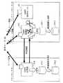
図2は、図1に示したメインルータ21とバックアップルータ22の構成を示す構成図である。図において、メインルータ21は、ネットワーク10に接続されるインターフェース(以下、「I/F」という)21aと、OSPFプロトコルによるデータ処理を行うOSPF処理部21bと、経路情報を格納する経路情報テーブル21cと、経路情報やハローメッセージなどのパケットの定期送信を制御するパケット定期送信制御部21dと、バックアップルータ22と伝送路25を介して接続され、パケット定期送信制御部21dの制御によってパケットの通信を行う通信部21eとから構成されている。
【0042】
また、バックアップルータ22は、ネットワーク10に接続されるI/F22aと、OSPFプロトコルによるデータ処理を行うOSPF処理部22bと、経路情報を格納する経路情報テーブル22cと、メインルータ21から受信するパケットの受信監視を行うパケット受信監視部22dと、メインルータ21と伝送路25を介して接続され、パケットの通信を行う通信部21eと、I/F22aに接続され、OSPFプロトコルを用いて他のルータ30と経路情報の交換を行う仮想ルータ23と、仮想ルータ23が取得した経路情報を格納するルーティングテーブル24とから構成されている。
【0043】
なお、この実施の形態では、仮想ルータ23とルーティングテーブル24をバックアップルータ22と同一のユニットで構成している。このように、この実施の形態では、バックアップルータと仮想ルータをたとえば一つの単体のチップとすることで製造を容易にすることができる。もちろん、仮想ルータ23とルーティングテーブル24を、バックアップルータ22と別体で製造することも可能である。
【0044】
このメインルータ21においては、OSPF処理部21bは、OSPFのデータ処理機能として、I/F21aを介して他のルータ30と経路情報の交換を行い、受信した経路情報を経路情報テーブル21cの後述するLSDBに格納させるとともに、これら経路情報に基づいて最適経路を選出して経路情報テーブル21cの後述するフォワーディングテーブルに格納させている。また、OSPF処理部21bは、バックアップルータ22内のOSPF処理部22bと経路情報の同期をとって送出することで、バックアップルータ22と経路情報テーブル内の経路情報の共有化を図っている。
【0045】
また、このOSPF処理部21bは、ハローメッセージの送受信を、I/F21aを介して他のルータ30と行っており、このハローメッセージの受信状況に応じて、相手ルータ30との接続性を確認している。さらに、このOSPF処理部21bは、ルータ20内のバックアップルータ22にも、このハローメッセージを送信するように、パケット定期送信制御部21dに指示を送っている。
【0046】
パケット定期送信制御部21dは、このOSPF処理部21bの指示に基づいて、通信部21eから定期的にハローメッセージを、伝送路25を介してバックアップルータ22に送信させている。
【0047】
バックアップルータ22においては、パケット受信監視部22dは、通信部22eで受信されたハローメッセージをモニタしており、パケット受信監視部22dは、一定時間内にこのハローメッセージがモニタできたかどうかをOSPF処理部22bに通知している。OSPF処理部22bは、一定時間内にこのハローメッセージがモニタできない旨の通知を受けた場合には、メインルータ21に故障が発生したと判断して、スタンバイ状態からアクティブ状態に動作を遷移させる。
【0048】
OSPF処理部22bは、OSPFのデータ処理機能として、アクティブ状態の時にI/F22aを介して他のルータ30と経路情報の交換を行い、受信した経路情報を経路情報テーブル22cの後述するLSDBに格納させるとともに、仮想ルータ23を起動させて、他のルータ30と経路情報の交換を行わせ、仮想ルータ23が受信した経路情報を経路情報テーブル22cの後述するLSDBに格納させている。また、OSPF処理部22bは、メインルータ21内のOSPF処理部21bと経路情報の同期をとって、経路情報テーブル22c内の経路情報の共有化を図っている。
【0049】
経路情報テーブル21c,22cは、他のルータと交換された経路情報および自ルータ内の他の論理ルータと同期がとられた経路情報を格納するリンクステートデータベース(以下、「LSDB」という)と、これら経路情報に基づいて選出された最適経路を格納するフォワーディングテーブルとからそれぞれ構成されている。
【0050】
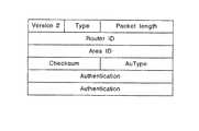
次に、これらルータ20,30間、またはルータ20内の論理ルータ21,22間で送受信されるOSPFの使用するメッセージのフォーマットを図3〜図5のメッセージの各構成図に基づいて説明する。OSPFのメッセージヘッダは、図示しないIPとTCPのヘッダに次いで、図3に示すOSPFのバージョン(Version)と、メッセージのタイプ(Type)と、メッセージの全長を示すパケット長(Packet length)と、このメッセージの送信元のルータのID(Router ID)と、このメッセージが所属するエリアのID(Area ID)と、このメッセージ全体のチェックサム(Checksum)と、このメッセージを認証するチェックの方法を示す認証タイプ(AuType)と、この認証タイプで指定された認証方法に応じて用いられる認証(Authentication)の各フィールドで構成されている。
【0051】
このメッセージのタイプには、隣り合うルータとの接続性を確認するためのハロー(Hello)と、隣り合うルータとの間で互いの持つリンクステートデータベースの内容の交換を行うためのデータベースディスクリプション(Database Description:以下、「DD」という)と、リンクステート情報の送信を要求するリンクステート要求(Link Status Request)と、要求されたリンクステート情報を送り返すためのリンクステートアップデート(Link Status Update)と、LSA(LinkStatus Advertisement)に対する受け取り確認を行うためのリンクステート確認(Link Status Acknowledgement)とがある。
【0052】
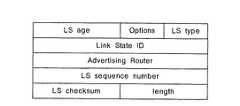
各ルータでは、このOSPFのメッセージヘッダに次いで上述した4つのメッセージのいずれかが送信されることとなり、たとえばリンクステート要求に応じてLSAを送信したり、リンクステートが変化した場合にLSAを送信する時には、リンクステートアップデートに次いでLSAが送信される。全てのLSAには、共通のヘッダが付加されて送信されており、このLSAのヘッダは、図4に示すように、このLSAが生成されてから経過した時間を示すLSエイジ(LSage)と、このメッセージを送出しているルータの持つオプション機能を示すオプション(Option)と、リンクステートのタイプを指定するためのLSタイプ(LS Type)と、LSタイプに応じたリンクステートのID(Link State ID)と、このLSAを生成したルータのIDを示すアドバタイジングルータ(Advertising Router)と、特定リンクに対して新しいLSAが生成される度に増加するシーケンス番号を示すLSシーケンスナンバー(LA sequence number)と、LSエイジフィールドを除くLSA全体に対するチェックサム(LS checksum)と、ヘッダも含めたLSA全体の長さ(length)とから構成されている。
【0053】
メインルータ21は、アップデートメッセージを用いて他のルータ30とOSPFの経路情報であるLSAを交換し、取得したLSAによってLSDBを構築するとともに、このLSAに基づいて最適経路を選出し、この最適経路情報によってフォワーディングテーブルを構築する。また、メインルータ21のOSPF処理部21bは、バックアップルータ22のOSPF処理部22bとの間で、このLSAを同期させる必要があり、このLSDB同期用のパケットフォーマットには、図3、図4に示したRFC2328と同様のパケットフォーマットを使用してLSAの同期をとっている。
【0054】
さらに、OSPF処理部21bでは、経路情報テーブル21cのLSDBの管理の他に、相手ルータ30の情報を管理する必要があり、この管理情報もOSPF処理部22bとの間で同期させる必要がある。図5は、この時に用いる同期用のパケットフォーマットであり、接続されるインターフェースの番号と、相手ルータ30とのステータスを示すルータステータスと、DDフラグと、送信時および受信時のDDシーケンス番号と、相手ルータ30のIDと、ネットワークを代表するルータ(Designated Router:以下、「DR」という)のDR IDと、DRのバックアップようとして機能するルータ(BackupDesignated Router:以下、「BDR」という)のBDR IDと、休止時間を示す休止タイマ(Inactivity Timer)と、再送時間を示す再送タイマ(Retransmit Timer)とから構成されている。
【0055】
一方、バックアップルータ22側では、仮想ルータ23が他のルータ30とOSPFの経路情報であるLSAを交換し、取得したLSAによってルーティングテーブル24を構築する。また、OSPF処理部22bは、仮想ルータ23(実際は仮想ルータ23の図示しないOSPF処理部)との間で、このLSAを同期させる必要があるので、図3、図4に示したRFC2328と同様のパケットフォーマットを使用してLSAの同期をとるとともに、相手ルータ30の情報を管理する必要から、図5に示したパケットフォーマットを使用して、この管理情報も仮想ルータ23との間で同期させている。
【0056】
次にこの実施の形態にかかるバックアップルータ22によるメインルータ21の故障監視アルゴリズムおよびメイン処理動作の監視アルゴリズムについて、図6〜図9の図面を用いて説明する。
【0057】
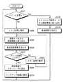
図6は、実施の形態1にかかるバックアップルータ22によるメインルータ21の故障監視アルゴリズムおよびメイン処理動作の監視アルゴリズムを説明するためのフローチャートであり、図7〜図9は、実施の形態1にかかるメインルータ21、バックアップルータ22および相手側のルータ30間でのデータの流れを示す概略ブロック図である。
【0058】
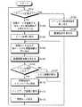
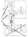
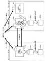
図6において、バックアップルータ22のOSPF処理部22bは、メインルータ21から定期送信されるハローメッセージが受信できるかどうかで、メインルータ21が正常かどうか判断している(ステップ101)。なお、ここでメインルータ21は、図7に示すように、ネットワーク10を介して相手側のルータ30とLSAの経路情報の交換を行って、経路情報テーブル21c内のLSDB21c1に格納するとともに、この経路情報から最適経路を選出してフォワーディングテーブル21c2に格納している。さらに、メインルータ21は、ハローメッセージを定期的にバックアップルータ22に送信しているものとする。
【0059】
この場合には、バックアップルータ22では、ハローメッセージが定期的に受信されるので、メインルータ21のアクティブ状態の動作は、正常と判断し、OSPF処理部22bは、メインルータ21から同期を取ってLSAの経路情報を取り込み(ステップ102)、経路情報テーブル22c内のLSDB22c1に格納するとともに、この経路情報から最適経路を選出してフォワーディングテーブル22c2に格納している(ステップ103)。
【0060】
また、メインルータ21からハローメッセージが受信できない場合には、OSPF処理部22bは、メインルータ21が故障したと判断して、メインルータ21との内部通信を中断して、仮想ルータ23を起動させ、相手側のルータ30と経路情報の交換を行わせ(ステップ104)、取得したこの経路情報をルーティングテーブル24に格納させるとともに、アクティブ状態のメイン処理に移行する(ステップ105)。
【0061】
このメイン処理に移行したバックアップルータ22では、OSPF処理部22bが相手側のルータ30と経路情報の交換を行い、仮想ルータ23で取得した経路情報と、相手側のルータ30から取得した経路情報を取り込み(ステップ106)、経路情報テーブル22cのLSDB22c1に格納するとともに、この経路情報から最適経路を選出してフォワーディングテーブル22c2に格納する(ステップ107)。
【0062】
なお、上述したOSPF処理部22bとルータ30間での経路情報の交換では、メイン処理への移行時にトポロジー変化に伴う経路情報の受信が不可能となるので、OSPF処理部22bが初期指定で初期ステートに戻って、事前に取得した経路情報に基づいてルータ30との間で全体の経路情報の交換を行って、経路情報を取得する。また、仮想ルータ23とルータ30間でも、初期ステートの状態で全体の経路情報の交換を行っている。
【0063】
次に、OAPF処理部22bは、メインルータ21の故障が復旧したかどうか、ハローメッセージの入力によって判断する(ステップ108)。ここで、このハローメッセージの入力がなく、依然としてメインルータ21が故障していると判断した場合には、アクティブ状態のメイン処理を続行し(ステップ109)、経路情報の取り込みを行う(ステップ106)。なお、この場合には、既に経路情報の交換が行われており、トポロジー変化に伴って変わった経路情報の交換のみを行うことができる。
【0064】
また、メインルータ21が故障から復旧した場合には、OSPF処理部22bは、図9に示すように、取得した全ての経路情報をメインルータ21に送出し(ステップ110)、スタンバイ状態のバックアップ処理に移行して(ステップ111)、ルータ30との経路情報の交換を停止する。そして、仮想ルータ23の動作を停止させて(ステップ112)、仮想ルータ23とルータ30の経路情報の交換を終了させてステップ101に戻る。
【0065】
メインルータ21では、故障から復旧すると、OSPF処理部21bが、復旧した旨の通知であるハローメッセージをバックアップルータ22に送信し、次にバックアップルータ22から全経路情報が送出されると、この全経路情報を取り込み、経路情報テーブル21cのLSDB21c1に格納するとともに、この経路情報から最適経路を選出してフォワーディングテーブル21c2に格納する。そして、OSPF処理部21bはハローメッセージを相手側のルータ30に送信して確認を行った後に、このルータ30と経路情報の交換を行う。
【0066】
このように、この実施の形態では、ルーティング制御処理を二重化するとともに仮想ルータを設けて、メインルータの故障時には、仮想ルータを起動させて隣り合う他のルータと経路情報の交換を行わせて、バックアップルータの経路情報の取得を可能にするので、バックアップルータは、事前にメインルータと同期させておいた経路情報に基づいてデータ処理を継続しつつ、仮想ルータを起動させ、他のルータから最新の経路情報を取得させ、かつ同期させて取り込むので、故障発生時にもトポロジー変化に伴う経路情報の受信を正確に行い、データの中継処理を停止させることなく、容易にデータ中継装置の二重化を実現することができる。
【0067】
(実施の形態2)
ところで、上述した実施の形態1では、メインルータ21の故障を判断した段階で仮想ルータ23を起動させて経路情報の取得を行わせているが、バックアップルータ22は、初期状態に戻って他のルータ30と全ての経路情報の交換を行わなければならないので、最新の経路情報の取得には時間がかかる場合がある。
【0068】
そこで、実施の形態2では、メインルータの故障前に仮想ルータを起動させることで、迅速に最新の経路情報を取得できるデータ中継方法を提供するものであり、データ中継装置の構成は、実施の形態1と同様であるが、その方法が異なるので、図10〜図12の図面を用いて、この実施の形態にかかるバックアップルータ22によるメインルータ21の故障監視アルゴリズムおよびメイン処理動作の監視アルゴリズムを説明する。
【0069】
図10は、実施の形態2にかかるバックアップルータ22によるメインルータ21の故障監視アルゴリズムおよびメイン処理動作の監視アルゴリズムを説明するためのフローチャートであり、図11、図12は、実施の形態2にかかるメインルータ、バックアップルータおよび相手側のルータ間でのデータの流れを示す概略ブロック図である。
【0070】
この実施の形態では、図11に示すように、仮想ルータ23は、事前に起動して相手側のルータ30と経路情報の交換を行って、取得した経路情報をルーティングテーブル24に格納するとともに、バックアップルータ22との間で同期をとって経路情報を送出している。
【0071】
このような状況下において、図10に示すように、バックアップルータのOSPF処理部22bは、実施の形態1と同様に、メインルータ21が正常かどうか判断しており(ステップ201)、正常の場合には、メインルータ21および仮想ルータ23と同期を取って経路情報を取り込み(ステップ202)、LSDB22c1に格納するとともに、最適経路を選出してフォワーディングテーブル22c2に格納する(ステップ203)。
【0072】
また、メインルータ21が正常でない場合には、OSPF処理部22bは、メインルータ21との内部通信を中断して(図8参照)、アクティブ状態のメイン処理に移行する(ステップ204)。次に、OSPF処理部22bは、仮想ルータ23から同期を取った最新の経路情報を取得して(ステップ205)、LSDB22c1に格納させるとともに、この経路情報に基づいて最適経路を選出する(ステップ206)。また、アクティブ状態のメイン処理に移行したバックアップルータ22では、OSPF処理部22bが相手側のルータ30と経路情報の交換を行い、仮想ルータ23で取得した経路情報と、相手側のルータ30から取得した経路情報を取り込み、経路情報テーブル22cのLSDB22c1に格納するとともに、この経路情報から最適経路を選出してフォワーディングテーブル22c2に格納している。
【0073】
次に、OAPF処理部22bは、メインルータ21の故障が復旧したかどうか判断し(ステップ207)、ここで依然としてメインルータ21が故障していると判断した場合には、アクティブ状態のメイン処理を続行し(ステップ208)、仮想ルータ23および相手側のルータ30から経路情報の取り込みを行う。
【0074】
また、メインルータ21からハローメッセージが送信されて、メインルータ21が故障から復旧した場合には、OSPF処理部22bは、図12に示すように、取得した全ての経路情報をメインルータ21に送出し(ステップ209)、スタンバイ状態のバックアップ処理に移行して(ステップ210)、ルータ30との経路情報の交換を停止する。この実施の形態では、バックアップルータ22がスタンバイ状態のバックアップ処理に移行しても、仮想ルータ23は、ルータ30との経路情報の交換動作を続行し、同期の取られた経路情報をバックアップルータ22に送出している。
【0075】
メインルータ21は、バックアップルータ22から経路情報を取得すると、この経路情報をLSDB21c1に格納するとともに、最適経路を選出してフォワーディングテーブル21c2に格納し、この経路情報に基づいて、相手側のルータ30と接続し、経路情報の交換を行う。
【0076】
このように、この実施の形態では、仮想ルータは、常に起動して最新の経路情報を取得してバックアップルータに送出しているので、メインルータに故障が発生しても、バックアップルータはトポロジー変化に伴って変わった最新の経路情報を正確に取り込むことができるので、迅速に最新の経路情報を取得でき、これによりデータの中継処理を停止させることなく、容易にデータ中継装置の二重化を実現することができる。
【0077】
(実施の形態3)
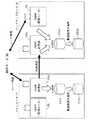
図13は、図1に示したメインルータとバックアップルータの他例の構成を示す構成図である。図において、メインルータ21が、図2に示したメインルータと異なる点は、OSPF処理部21bと通信部21eの間に、バックアップルータ22から受信するパケットの受信監視を行うパケット受信監視部21fを接続させた点と、OSPFプロトコルを用いてルータ30と経路情報の交換を行う仮想ルータ26をI/F21aに接続させ、かつこの仮想ルータ26が取得した経路情報を格納するルーティングテーブル27を、この仮想ルータ26に接続させた点である。
【0078】
なお、この実施の形態では、仮想ルータ26とルーティングテーブル27をメインルータ21と同一のユニットで構成している。このように、この実施の形態では、メインルータと仮想ルータをたとえば一つの単体のチップとすることで製造を容易にすることができる。もちろん、仮想ルータ26とルーティングテーブル27を、メインルータ21と別体で製造することも可能である。
【0079】
また、バックアップルータ22が、図2に示したバックアップルータと異なる点は、OSPF処理部22bと通信部22eの間に、経路情報やハローメッセージなどのパケットの定期送信を制御するパケット定期送信制御部22fを接続させ、メイン処理の動作に移行したときにこのパケット定期送信制御部22fから経路情報やハローメッセージを定期送信する点である。
【0080】
この実施の形態では、通常時には実施の形態2と同様に、メインルータ側では、OSPF処理部21bが相手側のルータ30と経路情報の交換を行っている。また、バックアップルータ側では、仮想ルータ23が起動して相手側のルータ30と経路情報の交換を行って、取得した経路情報をルーティングテーブル24に格納している。また、バックアップルータ22のOSPF処理部22bは、メインルータ21および仮想ルータ23と同期を取って経路情報を取り込んでいる。また、バックアップルータ22のOSPF処理部22bは、パケット受信監視部22dに受信したパケットを監視させている(図14参照)。なお、バックアップルータ22の動作フローは図10と同様である。
【0081】
このような状況下で、メインルータ21に故障が発生すると、OSPF処理部22bは、メインルータ21との内部通信を中断してアクティブ状態のメイン処理に移行し、仮想ルータ23から取得した経路情報に基づいて、相手側のルータ30と接続して経路情報の交換を行う(図15参照)。次に、メインルータ21の故障が復旧した場合には、バックアップルータ22は、メインルータ21と同期を取って全ての経路情報を送出し、スタンバイ状態のバックアップ処理に移行する。
【0082】
次に、復旧後のメインルータ21の動作を図16の概略ブロック図と、図17のフローチャートを用いて説明する。図17において、アクティブ状態でメイン処理を行うように設定されているOSPF処理部21bは、故障から復旧すると、復旧した旨の通知(ハローメッセージの送信)をバックアップルータ22に対して行う(ステップ301)。次に、バックアップルータ22から同期がとられて送られてくる経路情報を取り込み(ステップ302)、LSDB21c1に格納するとともに、仮想ルータ26を起動させて、相手側のルータ30との間で経路情報の交換を行わせる(ステップ303)。
【0083】
そして、OSPF処理部21bは、同期を取って仮想ルータ26が取得した経路情報を取り込んで、LSDB21c1に格納するとともに、このバックアップルータ22および仮想ルータ26から取得した経路情報に基づいて、最適経路を選出してフォワーディングテーブル21c2に格納する(ステップ304)。
【0084】
次に、OSPF処理部21bは、この取得した経路情報に基づいて、相手側のルータ30とネットワークを介して接続し、互いの経路情報の交換を行う(ステップ305)。なお、起動させた仮想ルータ26は、そのまま相手側のルータ30と経路情報の交換を行わせておいても良いし、または停止させても良い。
【0085】
このように、この実施の形態では、メインルータとバックアップルータを同一の構成にして、実施の形態2と同様の方法で経路情報の交換を正確に行うので、迅速に最新の経路情報を取得でき、これによりデータの中継処理を停止させることなく、容易にデータ中継装置の二重化を実現することができるとともに、メインルータとバックアップルータを同一の単体のチップで製造することができ、このチップの使用時には、同一チップを用い、内部設定のみでメインとバックアップを決めることができるので、メインとバックアップ別々のチップを製造する必要がなくなり、製造を容易にし、かつ製造コストを削減することができる。
【0086】
また、この構成の場合には、メインルータ21が故障から復旧しても、バックアップルータ22がアクティブ状態のメイン処理を続行し、メインルータ21は、スタンバイ状態のバックアップ処理を続行するように設定することも可能である。この場合には、バックアップルータ22のパケット定期送信制御部22fの制御によって、通信部22eから定期的にハローメッセージを、伝送路25を介してメインルータ21に送信する。
【0087】
メインルータ21では、このハローメッセージをパケット受信監視部21fで監視して、一定時間内にこのハローメッセージがモニタできたかどうかをOSPF処理部21bに通知し、OSPF処理部21bは、バックアップルータ22からハローメッセージが定期的に送信されている間は、スタンバイ状態のバックアップ処理を続行する。また、OSPF処理部21bは、一定時間内にこのハローメッセージがモニタできない旨の通知を受けた場合には、バックアップルータ22に故障が発生したと判断して、スタンバイ状態からアクティブ状態に動作を遷移させることも可能である。
【0088】
この場合には、チップ毎にメインやバックアップを設定する必要がなくなり、いずれにも使用が可能となるので、さらに汎用性が広がり、容易にデータ中継装置の二重化を図ることができる。
【0089】
この発明は、これら実施形態に限定されるものではなく、この発明の要旨を逸脱しない範囲で種々の変形実施が可能である。
【0090】
【発明の効果】
以上説明したように、この発明では、バックアップ側に仮想ルータを設け、メインルータとこの仮想ルータが、隣り合う他のデータ中継装置から最新の経路情報を取得して、バックアップルータにこの取得した経路情報を同期させて送出するので、バックアップルータは、取り込んだ最新の経路情報に基づき、最適経路を選出することが可能となり、これによりメインルータが故障しても、トポロジー変化に伴う経路情報の受信を正確に行い、データの中継処理を停止させることなく、容易にデータ中継装置の二重化を図ることができる。
【0091】
また、この発明では、メインルータが隣り合う他のデータ中継装置から最新の経路情報を取得して、バックアップルータにこの取得した経路情報を同期させて送出することで、バックアップルータで、取り込んだ最新の経路情報に基づき、最適経路の選出を可能にするとともに、バックアップルータでメインルータの故障を監視し、故障発生時には仮想ルータを起動させ、隣り合うデータ中継装置から最新の経路情報を取得させ、かつ同期させてバックアップルータに送出することで、バックアップルータは、依然に取り込んだ経路情報と仮想ルータから取り込んだ経路情報に基づき、最適経路の選出を行うので、メインルータが故障しても、トポロジー変化に伴う経路情報の受信を正確に行い、データの中継処理を停止させることなく、容易にデータ中継装置の二重化を図ることができる。
【0092】
また、この発明では、メインルータおよび仮想ルータが隣り合う他のデータ中継装置から最新の経路情報を取得して、バックアップルータにこの取得した経路情報を送出することで、バックアップルータでは、取り込んだ最新の経路情報に基づき、最適経路の選出を行えるとともに、バックアップルータでメインルータの故障を監視し、故障発生時には仮想ルータが隣り合うデータ中継装置から最新の経路情報を取得し、かつ同期させてバックアップルータに送出することで、バックアップルータは、メインルータと仮想ルータから取り込んだ経路情報に基づき、最適経路の選出を行うので、メインルータが故障しても、トポロジー変化に伴う経路情報の受信を正確に行い、データの中継処理を停止させることなく、容易にデータ中継装置の二重化を図ることができる。
【0093】
また、この発明では、バックアップルータにメインルータの故障復旧を監視させ、故障が復旧すると、メインルータと同期して格納している全ての経路情報をメインルータに送出することで、メインルータは、バックアップルータから取り込んだ経路情報に基づき、最適経路の選出を行うので、復旧後直ちにメインルータは、アクティブ状態のメイン処理を行うことが可能になるので、復旧時も、トポロジー変化に伴う経路情報の受信を正確に行い、データの中継処理を停止させることなく、容易にデータ中継装置の二重化を図ることができる。
【0094】
また、この発明では、バックアップルータと仮想ルータを同一のユニットで構成することで、バックアップルータと仮想ルータをたとえば一つの単体のチップとすることが可能となり、データ中継装置の製造を容易にすることができる。
【0095】
また、この発明では、メインルータに同期して、取得した経路情報を送出する仮想ルータを設け、メインルータがバックアップ処理を行う時には、仮想ルータから取り込まれた経路情報に基づいて、最適経路情報を選出するので、バックアップルータでのアクティブ状態のメイン処理およびメインルータでのスタンバイ状態のバックアップ処理を実現し、データの中継処理を停止させることなく、容易にデータ中継装置の二重化を図ることができる。
【0096】
また、この発明では、メインルータと仮想ルータを同一のユニットで構成することで、メインルータと仮想ルータをたとえば一つの単体のチップとすることが可能となり、データ中継装置の製造を容易にすることができる。
【0097】
また、この発明では、請求項6〜12のいずれか一つに記載のメインルータとバックアップルータと仮想ルータを設け、メインルータの故障時および復旧時に取り込んだ最新の経路情報に基づいて、最適経路を選出するので、故障時および復旧時も、トポロジー変化に伴う経路情報の受信を正確に行い、メインルータのデータの中継処理を停止させることなく、容易にデータ中継装置の二重化を図ることができる。
【図面の簡単な説明】
【図1】この発明にかかるデータ中継システムの概略構成の実施形態1を示すシステム構成図である。
【図2】図1に示したメインルータとバックアップルータの一例の構成を示す構成図である。
【図3】OSPFのメッセージヘッダのパケットフォーマットを示す構成図である。
【図4】LSAのメッセージヘッダのパケットフォーマットを示す構成図である。
【図5】相手ルータの情報を管理するするための同期用のパケットフォーマットを示す構成図である。
【図6】図2に示した実施の形態1にかかるバックアップルータによるメインルータの故障監視アルゴリズムおよびメイン処理動作の監視アルゴリズムを説明するためのフローチャートである。
【図7】実施の形態1にかかるメインルータ、バックアップルータおよび相手側のルータ間でのデータの流れを示す概略ブロック図である。
【図8】同じく、メインルータ、バックアップルータおよび相手側のルータ間でのデータの流れを示す概略ブロック図である。
【図9】同じく、メインルータ、バックアップルータおよび相手側のルータ間でのデータの流れを示す概略ブロック図である。
【図10】図2に示した実施の形態2にかかるバックアップルータによるメインルータの故障監視アルゴリズムおよびメイン処理動作の監視アルゴリズムを説明するためのフローチャートである。
【図11】同じく、メインルータ、バックアップルータおよび相手側のルータ間でのデータの流れを示す概略ブロック図である。
【図12】同じく、メインルータ、バックアップルータおよび相手側のルータ間でのデータの流れを示す概略ブロック図である。
【図13】図1に示したメインルータとバックアップルータの他例の構成を示す構成図である。
【図14】図13に示した実施の形態3にかかるメインルータ、バックアップルータおよび相手側のルータ間でのデータの流れを示す概略ブロック図である。
【図15】同じく、メインルータ、バックアップルータおよび相手側のルータ間でのデータの流れを示す概略ブロック図である。
【図16】同じく、メインルータ、バックアップルータおよび相手側のルータ間でのデータの流れを示す概略ブロック図である。
【図17】図13に示したメインルータによる復旧後のデータ処理動作を説明するためのフローチャートである。
【図18】データ中継システムの従来例の概略構成を示すシステム構成図である。
【符号の説明】
10 ネットワーク
20,30 ルータ
21 メインルータ(論理ルータ)
21a,22a インターフェース
21b,22b OSPF処理部
21c,22c 経路情報テーブル
21c1,22c1 LSDB
21c2,22c2 フォワーディングテーブル
21d,22f パケット定期送信制御部
21e,22e 通信部
21f,22d パケット受信監視部
22 バックアップルータ(論理ルータ)
23,26 仮想ルータ
24,27 ルーティングテーブル
25 伝送路[0001]
TECHNICAL FIELD OF THE INVENTION
The present invention relates to a data relay method, a data relay device, and a data relay system using the device, which are constructed by a plurality of logical data relay devices that perform a main process and a backup process, and particularly to another data relay device. The present invention relates to a data relay method for exchanging path information with a data relay device, a data relay device, and a data relay system using the device.
[0002]
[Prior art]
In a conventional data relay method, for example, as shown in Non-Patent
[0003]
In this data relay method, as shown in FIG. 18, a plurality of
[0004]
When the topology changes, the route information is exchanged quickly between the
[0005]
The
[0006]
This logical router is in an active state and performs a main process (hereinafter, referred to as a “main router”) 21. A logical router in which the operation is in a standby state and performs a backup process (hereinafter, a “backup router”) Each of the
[0007]
[Non-patent document 1]
John Moy, "RFC2328 OSPF Version 2" [online], Internet Official Protocol (STD1), April 1998, p. 6-15, AlterNIC The Network Information Center, [Searched January 22, 2003], Internet <URL: HYPERLINK ”http://www.alternic.org/rfcs/rfc2300/rfc2328.html”>
[0008]
[Problems to be solved by the invention]
However, in the above-described conventional example, if a failure occurs during the exchange of route information with another router and a packet loss occurs, the main router and the backup router cannot be completely synchronized, and the above-mentioned state switching is accompanied by a topology change during the state switching. Since routing information cannot be received, data relay processing becomes impossible and the service stops until the backup router returns to the initial state with the initial specification and acquires the entire routing information. there were.
[0009]
SUMMARY OF THE INVENTION The present invention has been made in view of the above-described problems, and achieves accurate reception of route information accompanying a topology change even when a failure occurs, and easily duplicates a data relay device without stopping data relay processing. It is an object to provide a data relay method, a data relay device, and a data relay system using the device.
[0010]
[Means for Solving the Problems]
In order to achieve the above object, in the data relay method according to
[0011]
According to the present invention, the first logical data relay device is in an active state by using the OSPF as a route information exchange protocol and duplicating the routing control process, for example, by a data relay method of relaying IP data. Similarly to the main router, the virtual router, which is the first communication device, obtains the latest route information from another adjacent data relay device, and the backup router, which is the second logical data relay device in the standby state, By selecting the optimum route based on the route information taken from the main router and the virtual router, the data relay device can be easily duplicated without stopping the data relay process.
[0012]
Further, in the data relay method according to claim 2, the plurality of data relay devices are logically set to a relationship between an active state and a standby state, and each of the plurality of data relay devices performs at least two logical data relay devices that perform a main process and a backup process. In the data relay method for constructing and relaying data, a first logical data relay device in an active state among the logical data relay devices uses a path exchange protocol for performing the data relay to transmit another data. A first exchange step of exchanging path information with the relay apparatus, and a transmission step of transmitting the exchanged path information from the first logical data relay apparatus to the second logical data relay apparatus in the standby state; A failure monitoring step of the second logical data relay device monitoring a failure of the first logical data relay device; The second logical data relay device transfers the data from the backup process to the main process, and the first communication device for obtaining route information executes a route exchange protocol for performing the data relay. A second exchange step of exchanging path information with the other data relay apparatus using the path information taken from at least one of the first logical data relay apparatus and the first communication apparatus. A first route selection step in which the second logical data relay device selects the optimum route information based on the first route selection information.
[0013]
According to the present invention, an OSPF is used as a routing information exchange protocol, a routing control process is duplicated, and a data relay method for relaying IP data is performed in the same manner as a main router which is an active logical data relay device. In addition, the virtual router as the first communication device acquires the latest route information from another adjacent data relay device, and the backup router as the standby logical data relay device detects the failure of the main router and performs backup. When the process is transferred to the router, the virtual router which is the first communication device is activated while continuing the data processing based on the route information which has been synchronized with the main router in advance, from the adjacent data relay device. By acquiring the latest route information and synchronizing, without stopping the data relay process Easily achieved duplication of data relay apparatus.
[0014]
In the data relay method according to the third aspect, the plurality of data relay devices are logically set to a relationship between an active state and a standby state, and each of the data relay devices includes at least two logical data relay devices that perform a main process and a backup process. In the data relay method for constructing and relaying data, the first logical data relay device in an active state and the first communication device for obtaining route information among the logical data relay devices are configured to perform the data relay. A first exchange step of exchanging path information with another data relay apparatus using a path exchange protocol, and transmitting the exchanged path information from the first logical data relay apparatus and the first communication apparatus; A sending step of sending to the second logical data relay device in the standby state, wherein the second logical data relay device transmits the first logical data to the second logical data relay device; A failure monitoring step of monitoring a failure of the relay device; a process transition step of transitioning the second logical data relay device from the backup process to the main process based on the monitoring result; A first path selecting step of selecting an optimum path based on the path information fetched by at least one of the first logical data relay apparatus and the first communication apparatus. I do.
[0015]
According to the present invention, the backup router, which is the logical data relay device in the standby state, uses the OSPF as the route information exchange protocol, duplicates the routing control process, and relays the IP data. When detecting the failure of the main router, which is the logical data relay device in the active state, and shifting the main processing to the backup router, while continuing the data processing based on the path information synchronized in advance with the main router By obtaining the latest route information from the virtual router in synchronization with the virtual router, the data relay device can be easily duplicated without stopping the data relay process.
[0016]
Further, in the data relay method according to claim 4, the second logical data relay device monitors the recovery of the first logical data relay device recognized as having failed, and the recovery monitoring result. A transmission step in which the second logical data relay apparatus that has shifted to the main processing transmits the fetched path information to the restored first logical data relay apparatus, and wherein the first logical data relay apparatus A second route selection step of selecting optimum route information based on the received route information.
[0017]
According to the present invention, when the backup router monitoring the main router recognizes that the failed main router has been recovered, the main router sends out the previously acquired route information in synchronization with the main router, and By enabling the main processing operation in the active state, the data relay apparatus can be easily duplicated without stopping the data relay processing at the time of recovery.
[0018]
Further, in the data relay method according to claim 5, the second communication device for acquiring the route information having the same function as the first communication device performs the backup processing of the first logical data relay device, A third exchange step of exchanging path information with another data relay apparatus using a path exchange protocol for performing the data relay, wherein the second path selection step includes the step of: The first logical data relay device selects optimal route information based on route information taken from at least one of a data relay device and the second communication device.
[0019]
According to the present invention, when the main router performs the backup process, the virtual router as the second communication device acquires the route information from another router, and based on the route information fetched from the own router and the virtual router, By selecting the optimal route information, the main processing in the active state at the backup router and the backup processing in the standby state at the main router are realized, and the data relay device can be easily duplicated without stopping the data relay processing. Aim.
[0020]
Further, in the data relay device according to claim 6, the data is logically set to a relationship between an active state and a standby state, and is configured by at least two logical data relay devices that perform a main process and a backup process, and performs data relay. In the relay device, a first communication device for acquiring path information is provided, and the first logical data relay device in an active state among the logical data relay devices and the first communication device are connected to the data relay device. Path exchange means for exchanging path information with another data relay device using a path exchange protocol for performing the path exchange protocol, and transferring the path information acquired by the exchange to the second logical data in the standby state. Sending means for sending to the relay device, wherein the second logical data relay device includes the first logical data relay device and the Based on the acquired path information from at least one first telecommunication device, characterized by comprising a first path selecting means for selecting an optimum route information.
[0021]
According to the present invention, an OSPF is used as an exchange protocol for routing information, and a routing control process is duplicated, and a data relay device for relaying IP data, wherein another data relay device in which a main router and a virtual router are adjacent to each other is used. By acquiring the latest route information from the backup router and sending the acquired route information to the backup router, the backup router can select the optimal route based on the latest route information acquired, thereby The data relay device can be easily duplicated without stopping the relay process.
[0022]
Further, in the data relay device according to claim 7, the data is set logically in a relationship between an active state and a standby state, and is constructed by at least two logical data relay devices that perform a main process and a backup process, and performs data relay. In the relay device, a first communication device for acquiring path information is provided, and the first logical data relay device in an active state among the logical data relay devices and the first communication device are connected to the data relay device. Path exchange means for exchanging path information with another data relay device using a path exchange protocol for performing the path exchange protocol, and transferring the path information acquired by the exchange to the second logical data in the standby state. Sending means for sending to the relay device, wherein the second logical data relay device monitors a failure of the first logical data relay device. A failure monitoring unit that performs processing from the backup processing to the main processing based on the monitoring result, causes the first communication device to exchange path information, and Transfer means for taking in information; and first route selecting means for selecting optimal route information based on route information taken from at least one of the first logical data relay device and the first communication device. It is characterized by the following.
[0023]
According to the present invention, the main router obtains the latest route information from another adjacent data relay device, and sends the obtained route information to the backup router. Based on the above, the optimal route can be selected, the backup router monitors the failure of the main router, activates the virtual router when a failure occurs, acquires the latest route information from the adjacent data relay device, and synchronizes This makes it possible to easily duplicate the data relay device without stopping the data relay process.
[0024]
Further, in the data relay device according to claim 8, the data is set logically in a relationship between an active state and a standby state, and is configured by at least two logical data relay devices that perform a main process and a backup process to perform data relay. In the relay device, a first communication device for acquiring path information is provided, and the first logical data relay device in an active state among the logical data relay devices and the first communication device are connected to the data relay device. Path exchange means for exchanging path information with another data relay device using a path exchange protocol for performing the path exchange protocol, and transferring the path information acquired by the exchange to the second logical data in the standby state. Sending means for sending to the relay device, wherein the second logical data relay device monitors a failure of the first logical data relay device. Failure monitoring means, a migration means for shifting processing from the backup processing to the main processing based on the monitoring result, and fetching from at least one of the first logical data relay device and the first communication device. A first route selecting means for selecting optimum route information based on the route information.
[0025]
According to the present invention, the main router and the virtual router acquire the latest route information from another adjacent data relay device, and send the acquired route information to the backup router, so that the backup router acquires the latest route information. Based on the route information, the optimal route can be selected, and the backup router monitors the main router for failure, and when a failure occurs, the virtual router acquires the latest route information from the adjacent data relay device and synchronizes it. By sending the data to the backup router, the data relay device can be easily duplicated without stopping the data relay process.
[0026]
Further, in the data relay device according to claim 9, the second logical data relay device captures the data based on the recovery monitoring means for monitoring the recovery of the first logical data relay device and the monitoring result of the recovery. Sending means for sending the path information to the restored first logical data relay apparatus, wherein the first logical data relay apparatus determines optimal path information based on the path information taken in after the restoration. It is characterized by further comprising a second route selecting means for selecting.
[0027]
According to the present invention, the backup router monitors the recovery of the failure of the main router, and when the failure is recovered, sends out the route information acquired in advance in synchronization with the main router, and performs the main processing operation in the active state in the main router. This makes it possible to easily duplicate the data relay device without stopping the data relay process even at the time of recovery.
[0028]
Further, in the data relay device according to
[0029]
According to the present invention, the backup router and the virtual router are configured by the same unit, so that the backup router and the virtual router are made into, for example, one single chip, thereby facilitating the manufacture.
[0030]
The data relay device according to claim 11, further comprising a second communication device having a function similar to that of the first communication device, wherein the second communication device is a communication device of the first logical data relay device. At the time of the backup processing, the path information is exchanged with the other data relay apparatus using the path exchange protocol for performing the data relay, and the acquired path information is transmitted to the first logical data relay apparatus. It is characterized by doing.
[0031]
According to the present invention, a virtual router for transmitting the acquired route information to the main router is provided, and when the main router performs the backup process in the standby state, the optimal route information is selected based on the route information taken from the virtual router. By doing so, the main processing in the active state in the backup router and the backup processing in the standby state in the main router are realized, and the data relay device can be easily duplicated without stopping the data relay processing.
[0032]
Further, in the data relay device according to claim 12, the first logical data relay device and the second communication device are configured in the same unit.
[0033]
According to the present invention, since the main router and the virtual router are configured by the same unit, the manufacturing is facilitated by forming the main router and the virtual router into one single chip, for example.
[0034]
Further, in the data relay system according to the thirteenth aspect, a data relay device configured by at least two logical data relay devices that are logically set to a relationship between an active state and a standby state and perform a main process and a backup process is connected. A data relay system for relaying data, comprising the data relay device according to any one of claims 6 to 12, and exchanging path information between the data relay device and another data relay device. It is characterized by the following.
[0035]
According to the present invention, the main router, the backup router, and the virtual router according to any one of claims 6 to 12 are provided, and the optimum route is determined based on the latest route information acquired when the main router fails and recovers. , The data relay device can be easily duplicated without stopping the data relay process.
[0036]
BEST MODE FOR CARRYING OUT THE INVENTION
Hereinafter, preferred embodiments of a data relay method, a data relay device, and a data relay system using the data relay device according to the present invention will be described with reference to the accompanying drawings of FIGS. In the following drawings, the same components as those in FIG. 18 are denoted by the same reference numerals for convenience of explanation.
[0037]
(Embodiment 1)
FIG. 1 is a system configuration diagram showing a schematic configuration of a data relay system according to the present invention. In the figure, the data relay system of this embodiment has a plurality of
[0038]
The
[0039]
In the
[0040]
Therefore, in this embodiment, another router (virtual router) 23 is virtually provided in the
[0041]
FIG. 2 is a configuration diagram showing a configuration of the
[0042]
The
[0043]
In this embodiment, the
[0044]
In the
[0045]
The
[0046]
The packet periodic
[0047]
In the
[0048]
As a data processing function of the OSPF, the
[0049]
The path information tables 21c and 22c include a link state database (hereinafter, referred to as “LSDB”) storing path information exchanged with another router and path information synchronized with another logical router in the own router. And a forwarding table for storing the optimum route selected based on the route information.
[0050]
Next, the format of a message used by the OSPF transmitted and received between the
[0051]
This message type includes a hello (Hello) for confirming connectivity with an adjacent router, and a database description (Hello) for exchanging the contents of a link state database with each other between adjacent routers. Database Description: a link state request for requesting transmission of link state information (Link Status Request), a link state update for sending back the requested link state information (Link Status Update), There is a link state confirmation (Link Status Acknowledgement) for confirming reception of an LSA (Link Status Advertisement).
[0052]
Each of the routers transmits one of the above four messages following the OSPF message header. For example, the router transmits an LSA in response to a link state request, or transmits an LSA when the link state changes. Occasionally, an LSA is transmitted following a link state update. A common header is added to all the LSAs and transmitted. As shown in FIG. 4, the header of the LSA includes an LS age (LSage) indicating a time elapsed since the generation of the LSA, An option (Option) indicating an optional function of the router sending this message, an LS type (LS Type) for designating a link state type, and a link state ID (Link State ID) corresponding to the LS type. ), An advertising router (Advertising Router) indicating the ID of the router that generated the LSA, an LS sequence number (LA sequence number) indicating a sequence number that increases each time a new LSA is generated for a specific link, L excluding LS Age field Checksum (LS checksum) to the total A, is configured from a length of the entire LSA which including a header and (length).
[0053]
The
[0054]
Further, the
[0055]
On the other hand, on the
[0056]
Next, a failure monitoring algorithm of the
[0057]
FIG. 6 is a flowchart for explaining the failure monitoring algorithm of the
[0058]
6, the
[0059]
In this case, since the hello message is periodically received by the
[0060]
When the hello message cannot be received from the
[0061]
In the
[0062]
In the above-described exchange of the path information between the
[0063]
Next, the
[0064]
When the
[0065]
When the
[0066]
Thus, in this embodiment, the routing control processing is duplicated and a virtual router is provided, and when the main router fails, the virtual router is activated to exchange the route information with another adjacent router, Since the backup router's route information can be obtained, the backup router starts the virtual router while continuing data processing based on the route information synchronized in advance with the main router, and activates the latest router from other routers. Route information is acquired and synchronized, so even in the event of a failure, route information is accurately received due to a topology change, and data relay devices can be easily duplicated without stopping data relay processing. can do.
[0067]
(Embodiment 2)
By the way, in the above-described first embodiment, the
[0068]
Therefore, the second embodiment provides a data relay method that can quickly obtain the latest route information by activating a virtual router before the main router fails. The configuration of the data relay device is as follows. Since the method is the same as that of the first embodiment, but the method is different, a failure monitoring algorithm of the
[0069]
FIG. 10 is a flowchart for explaining the failure monitoring algorithm of the
[0070]
In this embodiment, as shown in FIG. 11, the
[0071]
Under such circumstances, as shown in FIG. 10, the
[0072]
If the
[0073]
Next, the
[0074]
When the hello message is transmitted from the
[0075]
Upon acquiring the route information from the
[0076]
As described above, in this embodiment, the virtual router always starts up, obtains the latest route information, and sends it to the backup router. Therefore, even if a failure occurs in the main router, the backup router changes topology. The latest route information that has changed along with the information can be accurately captured, so that the latest route information can be quickly acquired, thereby easily realizing the duplexing of the data relay device without stopping the data relay process. be able to.
[0077]
(Embodiment 3)
FIG. 13 is a configuration diagram showing a configuration of another example of the main router and the backup router shown in FIG. In the figure, the
[0078]
In this embodiment, the
[0079]
The
[0080]
In this embodiment, the
[0081]
In such a situation, when a failure occurs in the
[0082]
Next, the operation of the
[0083]
Then, the
[0084]
Next, based on the obtained route information, the
[0085]
As described above, in this embodiment, the main router and the backup router have the same configuration, and the route information is exchanged accurately in the same manner as in the second embodiment, so that the latest route information can be obtained quickly. This allows the data relay device to be easily duplicated without stopping the data relay process, and the main router and the backup router can be manufactured using the same single chip. In some cases, the main chip and the backup chip can be determined only by the internal setting using the same chip, so that it is not necessary to manufacture separate chips for the main chip and the backup chip, thereby facilitating the manufacturing and reducing the manufacturing cost.
[0086]
In this configuration, even if the
[0087]
In the
[0088]
In this case, there is no need to set a main or backup for each chip, and it is possible to use any of them, so that the versatility is further expanded and the data relay device can be easily duplicated.
[0089]
The present invention is not limited to these embodiments, and various modifications can be made without departing from the spirit of the present invention.
[0090]
【The invention's effect】
As described above, according to the present invention, a virtual router is provided on the backup side, and the main router and the virtual router obtain the latest route information from another adjacent data relay device, and the obtained route is transferred to the backup router. Since the information is sent out synchronously, the backup router can select the optimum route based on the latest route information taken in, so that even if the main router fails, the route information can be received according to the topology change. And the data relay device can be easily duplicated without stopping the data relay process.
[0091]
Further, in the present invention, the main router acquires the latest route information from another adjacent data relay device and synchronizes the acquired route information with the backup router to send the acquired route information. Based on the route information, the optimal route can be selected, the backup router monitors the failure of the main router, activates the virtual router when a failure occurs, and obtains the latest route information from the adjacent data relay device, By synchronizing and sending to the backup router, the backup router selects the optimum route based on the route information still taken in and the route information taken from the virtual router. It accurately receives the route information accompanying the change, and without stopping the data relay process, It is possible to duplication of data relay apparatus.
[0092]
Further, in the present invention, the main router and the virtual router acquire the latest route information from another adjacent data relay device, and transmit the acquired route information to the backup router. In addition to selecting the optimal route based on the routing information, the backup router monitors the failure of the main router, and when a failure occurs, the virtual router acquires the latest routing information from the adjacent data relay device and synchronizes it for backup. By sending the information to the router, the backup router selects the optimal route based on the route information fetched from the main router and the virtual router, so even if the main router fails, it can correctly receive the route information associated with the topology change. To the data relay device easily without stopping the data relay process. It is possible to reduce the duplication.
[0093]
Further, according to the present invention, the backup router monitors the failure recovery of the main router, and when the failure is recovered, all the stored route information is transmitted to the main router in synchronization with the main router, so that the main router can Since the best route is selected based on the route information fetched from the backup router, the main router can perform the main processing in the active state immediately after restoration. Reception can be accurately performed, and the data relay device can be easily duplicated without stopping the data relay process.
[0094]
Further, according to the present invention, by configuring the backup router and the virtual router with the same unit, the backup router and the virtual router can be formed as, for example, one single chip, thereby facilitating the manufacture of the data relay device. Can be.
[0095]
Further, in the present invention, a virtual router for transmitting the acquired route information is provided in synchronization with the main router, and when the main router performs the backup process, the optimal route information is obtained based on the route information taken from the virtual router. Therefore, the main processing in the active state in the backup router and the backup processing in the standby state in the main router are realized, and the data relay device can be easily duplicated without stopping the data relay processing.
[0096]
Further, according to the present invention, by configuring the main router and the virtual router by the same unit, the main router and the virtual router can be formed as one single chip, for example, and the manufacture of the data relay device is facilitated. Can be.
[0097]
According to the present invention, a main router, a backup router, and a virtual router according to any one of claims 6 to 12 are provided, and an optimal route is determined based on the latest route information acquired when the main router fails and recovers. Therefore, even in the event of a failure or recovery, it is possible to accurately receive the route information associated with the topology change, and to easily duplicate the data relay device without stopping the data relay process of the main router. .
[Brief description of the drawings]
FIG. 1 is a system configuration diagram showing a first embodiment of a schematic configuration of a data relay system according to the present invention.
FIG. 2 is a configuration diagram illustrating an example of a configuration of a main router and a backup router illustrated in FIG. 1;
FIG. 3 is a configuration diagram showing a packet format of a message header of OSPF.
FIG. 4 is a configuration diagram illustrating a packet format of an LSA message header.
FIG. 5 is a configuration diagram illustrating a synchronization packet format for managing information of a partner router.
FIG. 6 is a flowchart for explaining a main router failure monitoring algorithm and a main processing operation monitoring algorithm by the backup router according to the first embodiment shown in FIG. 2;
FIG. 7 is a schematic block diagram illustrating a flow of data among a main router, a backup router, and a counterpart router according to the first embodiment;
FIG. 8 is a schematic block diagram showing a data flow between a main router, a backup router, and a counterpart router.
FIG. 9 is a schematic block diagram showing a data flow between a main router, a backup router, and a counterpart router.
FIG. 10 is a flowchart for explaining a failure monitoring algorithm of a main router and a monitoring algorithm of a main processing operation by the backup router according to the second embodiment shown in FIG. 2;
FIG. 11 is a schematic block diagram showing the flow of data among a main router, a backup router, and a router on the other end.
FIG. 12 is a schematic block diagram showing a data flow between a main router, a backup router, and a partner router.
FIG. 13 is a configuration diagram showing a configuration of another example of the main router and the backup router shown in FIG. 1;
FIG. 14 is a schematic block diagram showing a data flow between a main router, a backup router, and a partner router according to the third embodiment shown in FIG.
FIG. 15 is a schematic block diagram showing the flow of data among a main router, a backup router, and a router on the other end.
FIG. 16 is a schematic block diagram showing a data flow among a main router, a backup router, and a partner router.
FIG. 17 is a flowchart for explaining a data processing operation after restoration by the main router shown in FIG. 13;
FIG. 18 is a system configuration diagram showing a schematic configuration of a conventional example of a data relay system.
[Explanation of symbols]
10 Network
20, 30 router
21 Main router (logical router)
21a, 22a interface
21b, 22b OSPF processing unit
21c, 22c route information table
21c1, 22c1 LSDB
21c2, 22c2 forwarding table
21d, 22f Packet periodic transmission control unit
21e, 22e Communication unit
21f, 22d Packet reception monitoring unit
22 Backup router (logical router)
23,26 Virtual router
24, 27 routing table
25 Transmission line
Claims (13)
Translated fromJapanese前記論理データ中継装置のうちのアクティブ状態の第1の論理データ中継装置と経路情報取得用の第1の通信装置が、前記データ中継を行うための経路交換プロトコルを使用して、他のデータ中継装置と経路情報の交換を行うとともに、該交換によって取得された経路情報を前記スタンバイ状態の第2の論理データ中継装置に送出し、前記第1の論理データ中継装置および前記第1の通信装置の少なくとも一つから取り込んだ前記経路情報に基づき、前記第2の論理データ中継装置が最適経路情報を選出することを特徴とするデータ中継方法。A data relay method in which a plurality of data relay devices are logically set in a relationship between an active state and a standby state, and each of which constructs at least two logical data relay devices that perform a main process and a backup process and relays data,
The first logical data relay device in the active state and the first communication device for obtaining route information among the logical data relay devices are configured to perform another data relay using a route exchange protocol for performing the data relay. Exchanges path information with the device, and sends the path information obtained by the exchange to the second logical data relay apparatus in the standby state, and transmits the path information of the first logical data relay apparatus and the first communication apparatus. A data relay method, wherein the second logical data relay device selects optimal path information based on the path information fetched from at least one.
前記論理データ中継装置のうちのアクティブ状態の第1の論理データ中継装置が、前記データ中継を行うための経路交換プロトコルを使用して、他のデータ中継装置と経路情報の交換を行う第1の交換工程と、
前記交換された経路情報を前記第1の論理データ中継装置から前記スタンバイ状態の第2の論理データ中継装置に送出する送出工程と、
前記第2の論理データ中継装置が、前記第1の論理データ中継装置の故障を監視する故障監視工程と、
前記監視結果に基づいて、前記第2の論理データ中継装置が前記バックアップ処理から前記メイン処理に移行する処理移行工程と、
経路情報取得用の第1の通信装置が、前記データ中継を行うための経路交換プロトコルを使用して、前記他のデータ中継装置と経路情報の交換を行う第2の交換工程と、
前記第1の論理データ中継装置および前記第1の通信装置の少なくとも一つから取り込まれた経路情報に基づいて、前記第2の論理データ中継装置が最適経路情報を選出する第1の経路選出工程と、
を含むことを特徴とするデータ中継方法。A data relay method in which a plurality of data relay devices are logically set in a relationship between an active state and a standby state, and each of which constructs at least two logical data relay devices that perform a main process and a backup process and relays data,
A first logical data relay device in an active state among the logical data relay devices exchanges route information with another data relay device using a route exchange protocol for performing the data relay. Replacement process,
A sending step of sending the exchanged path information from the first logical data relay device to the second logical data relay device in the standby state;
A failure monitoring step in which the second logical data relay device monitors a failure of the first logical data relay device;
A process transition step in which the second logical data relay device transitions from the backup process to the main process based on the monitoring result;
A first communication device for acquiring route information, a second exchange process of exchanging route information with the other data relay device using a route exchange protocol for performing the data relay;
A first path selecting step in which the second logical data relay apparatus selects optimum path information based on path information taken from at least one of the first logical data relay apparatus and the first communication apparatus; When,
A data relay method comprising:
前記論理データ中継装置のうちのアクティブ状態の第1の論理データ中継装置と経路情報取得用の第1の通信装置が、前記データ中継を行うための経路交換プロトコルを使用して、他のデータ中継装置と経路情報の交換を行う第1の交換工程と、
前記交換された経路情報を前記第1の論理データ中継装置および前記第1の通信装置から前記スタンバイ状態の第2の論理データ中継装置に送出する送出工程と、
前記第2の論理データ中継装置が前記第1の論理データ中継装置の故障を監視する故障監視工程と、
前記監視結果に基づいて、前記第2の論理データ中継装置が前記バックアップ処理から前記メイン処理に移行する処理移行工程と、
前記第2の論理データ中継装置が前記第1の論理データ中継装置および前記第1の通信装置の少なくとも一つによって取り込まれた前記経路情報に基づいて、最適経路を選出する第1の経路選出工程と、
を含むことを特徴とするデータ中継方法。A data relay method in which a plurality of data relay devices are logically set in a relationship between an active state and a standby state, and each of which constructs at least two logical data relay devices that perform a main process and a backup process and relays data,
The first logical data relay device in the active state and the first communication device for obtaining route information among the logical data relay devices are configured to perform another data relay using a route exchange protocol for performing the data relay. A first exchange step of exchanging path information with the device;
A sending step of sending the exchanged path information from the first logical data relay device and the first communication device to the second logical data relay device in the standby state;
A failure monitoring step in which the second logical data relay device monitors a failure of the first logical data relay device;
A process transition step in which the second logical data relay device transitions from the backup process to the main process based on the monitoring result;
A first route selection step in which the second logical data relay device selects an optimal route based on the route information fetched by at least one of the first logical data relay device and the first communication device When,
A data relay method comprising:
前記復旧の監視結果に基づき、前記メイン処理に移行した第2の論理データ中継装置が、取り込んだ前記経路情報を前記復旧した第1の論理データ中継装置に送信する送信工程と、
前記第1の論理データ中継装置が、受信した前記経路情報に基づいて最適経路情報を選出する第2の経路選出工程と、
をさらに含むことを特徴とする請求項2または3に記載のデータ中継方法。In the data relay method, the second logical data relay device monitors a recovery of the first logical data relay device recognized as having failed, a recovery monitoring step;
Based on the monitoring result of the recovery, a second logical data relay device that has shifted to the main process, transmitting the captured path information to the recovered first logical data relay device;
A second route selection step in which the first logical data relay device selects optimal route information based on the received route information;
The data relay method according to claim 2, further comprising:
前記第2の経路選出工程では、前記第2の論理データ中継装置および前記第2の通信装置の少なくとも一つから取り込まれた経路情報に基づいて、前記第1の論理データ中継装置が最適経路情報を選出することを特徴とする請求項4に記載のデータ中継方法。In the data relay method, a second communication device for acquiring path information having a function similar to that of the first communication device performs the data relay during backup processing of the first logical data relay device. A third exchange step of exchanging path information with another data relay device using a path exchange protocol for
In the second route selection step, the first logical data relay device determines optimum route information based on route information taken from at least one of the second logical data relay device and the second communication device. 5. The data relay method according to claim 4, wherein the data relay method is selected.
経路情報を取得するための第1の通信装置を、
備え、かつ前記論理データ中継装置のうちのアクティブ状態の第1の論理データ中継装置と前記第1の通信装置は、
前記データ中継を行うための経路交換プロトコルを使用して、他のデータ中継装置と経路情報の交換を行う第1の経路交換手段と、
前記交換によって取得された経路情報を前記スタンバイ状態の第2の論理データ中継装置に送出する送出手段と、
を備え、前記第2の論理データ中継装置は、
前記第1の論理データ中継装置および前記第1の通信装置の少なくとも一つから取り込んだ経路情報に基づき、最適経路情報を選出する第1の経路選出手段とを備えたことを特徴とするデータ中継装置。In a data relay device that is logically set in a relationship between an active state and a standby state, is configured by at least two logical data relay devices that perform a main process and a backup process, and performs data relay,
A first communication device for acquiring the route information,
The first logical data relay device and the first communication device in an active state among the logical data relay devices,
A first route exchange unit for exchanging route information with another data relay device using the route exchange protocol for performing the data relay,
Sending means for sending the path information obtained by the exchange to the second logical data relay device in the standby state;
Wherein the second logical data relay device comprises:
Data relay comprising: first path selecting means for selecting optimum path information based on path information fetched from at least one of the first logical data relay apparatus and the first communication apparatus. apparatus.
経路情報を取得するための第1の通信装置を、
備え、かつ前記論理データ中継装置のうちのアクティブ状態の第1の論理データ中継装置と前記第1の通信装置は、
前記データ中継を行うための経路交換プロトコルを使用して、他のデータ中継装置と経路情報の交換を行う第1の経路交換手段と、
前記交換によって取得された経路情報を前記スタンバイ状態の第2の論理データ中継装置に送出する送出手段と、
を備え、前記第2の論理データ中継装置は、
前記第1の論理データ中継装置の故障を監視する故障監視手段と、
前記監視結果に基づいて、処理を前記バックアップ処理から前記メイン処理に移行させ、前記第1の通信装置に経路情報の交換を行わせて、該第1の通信装置から経路情報を取り込む移行手段と、
前記第1の論理データ中継装置および前記第1の通信装置の少なくとも一つから取り込んだ経路情報に基づき、最適経路情報を選出する第1の経路選出手段と、
を備えたことを特徴とするデータ中継装置。In a data relay device that is logically set in a relationship between an active state and a standby state, is configured by at least two logical data relay devices that perform a main process and a backup process, and performs data relay,
A first communication device for acquiring the route information,
The first logical data relay device and the first communication device in an active state among the logical data relay devices,
A first route exchange unit for exchanging route information with another data relay device using the route exchange protocol for performing the data relay,
Sending means for sending the path information obtained by the exchange to the second logical data relay device in the standby state;
Wherein the second logical data relay device comprises:
Failure monitoring means for monitoring a failure of the first logical data relay device;
Based on the monitoring result, shifting processing from the backup processing to the main processing, causing the first communication device to exchange path information, and taking path information from the first communication apparatus; ,
First path selecting means for selecting optimum path information based on path information taken from at least one of the first logical data relay device and the first communication device;
A data relay device comprising:
経路情報を取得するための第1の通信装置を、
備え、かつ前記論理データ中継装置のうちのアクティブ状態の第1の論理データ中継装置と前記第1の通信装置は、
前記データ中継を行うための経路交換プロトコルを使用して、他のデータ中継装置と経路情報の交換を行う第1の経路交換手段と、
前記交換によって取得された経路情報を前記スタンバイ状態の第2の論理データ中継装置に送出する送出手段と、
を備え、前記第2の論理データ中継装置は、
前記第1の論理データ中継装置の故障を監視する故障監視手段と、
前記監視結果に基づいて、処理を前記バックアップ処理から前記メイン処理に移行させる移行手段と、
前記第1の論理データ中継装置および前記第1の通信装置の少なくとも一つから取り込んだ経路情報に基づき、最適経路情報を選出する第1の経路選出手段と、
を備えたことを特徴とするデータ中継装置。In a data relay device that is logically set in a relationship between an active state and a standby state, is configured by at least two logical data relay devices that perform a main process and a backup process, and performs data relay,
A first communication device for acquiring the route information,
The first logical data relay device and the first communication device in an active state among the logical data relay devices,
A first route exchange unit for exchanging route information with another data relay device using the route exchange protocol for performing the data relay,
Sending means for sending the path information obtained by the exchange to the second logical data relay device in the standby state;
Wherein the second logical data relay device comprises:
Failure monitoring means for monitoring a failure of the first logical data relay device;
A shift unit that shifts a process from the backup process to the main process based on the monitoring result;
First path selecting means for selecting optimum path information based on path information taken from at least one of the first logical data relay device and the first communication device;
A data relay device comprising:
前記第1の論理データ中継装置の復旧を監視する復旧監視手段と、
前記復旧の監視結果に基づき、取り込んだ前記経路情報を前記復旧した第1の論理データ中継装置に送出する送出手段と、
をさらに備え、前記第1の論理データ中継装置は、
前記復旧後に取り込んだ前記経路情報に基づいて、最適経路情報を選出する第2の経路選出手段をさらに備えたことを特徴とする請求項6〜8のいずれか一つに記載のデータ中継装置。In the data relay device, the second logical data relay device includes:
Recovery monitoring means for monitoring recovery of the first logical data relay device;
Sending means for sending the fetched path information to the restored first logical data relay device based on the restoration monitoring result;
The first logical data relay device further comprises:
The data relay device according to any one of claims 6 to 8, further comprising a second route selection unit that selects optimal route information based on the route information captured after the restoration.
前記第2の通信装置は、前記第1の論理データ中継装置のバックアップ処理の際に、前記データ中継を行うための経路交換プロトコルを使用して、前記他のデータ中継装置と経路情報の交換を行い、取得した経路情報を前記第1の論理データ中継装置に送出することを特徴とする請求項6〜10のいずれか一つに記載のデータ中継装置。The data relay device further includes a second communication device having the same function as the first communication device,
The second communication device exchanges route information with the other data relay device using a route exchange protocol for performing the data relay at the time of backup processing of the first logical data relay device. The data relay device according to any one of claims 6 to 10, wherein the route information is transmitted to the first logical data relay device.
請求項6〜12のいずれか一つのデータ中継装置を備え、該データ中継装置と他のデータ中継装置との間で経路情報の交換を行うことを特徴とするデータ中継システム。In a data relay system configured to be logically set to a relationship between an active state and a standby state, and connected by a data relay device configured by at least two logical data relay devices that perform a main process and a backup process, and relaying data,
A data relay system comprising the data relay device according to any one of claims 6 to 12, wherein route information is exchanged between the data relay device and another data relay device.
Priority Applications (1)
| Application Number | Priority Date | Filing Date | Title |
|---|---|---|---|
| JP2003067270AJP3604380B2 (en) | 2003-03-12 | 2003-03-12 | Data relay method, data relay device, and data relay system using the device |
Applications Claiming Priority (1)
| Application Number | Priority Date | Filing Date | Title |
|---|---|---|---|
| JP2003067270AJP3604380B2 (en) | 2003-03-12 | 2003-03-12 | Data relay method, data relay device, and data relay system using the device |
Publications (2)
| Publication Number | Publication Date |
|---|---|
| JP2004282176A JP2004282176A (en) | 2004-10-07 |
| JP3604380B2true JP3604380B2 (en) | 2004-12-22 |
Family
ID=33284929
Family Applications (1)
| Application Number | Title | Priority Date | Filing Date |
|---|---|---|---|
| JP2003067270AExpired - Fee RelatedJP3604380B2 (en) | 2003-03-12 | 2003-03-12 | Data relay method, data relay device, and data relay system using the device |
Country Status (1)
| Country | Link |
|---|---|
| JP (1) | JP3604380B2 (en) |
Families Citing this family (3)
| Publication number | Priority date | Publication date | Assignee | Title |
|---|---|---|---|---|
| KR20060068532A (en)* | 2004-12-16 | 2006-06-21 | 한국전자통신연구원 | Router Redundancy Device Using Fault Tolerant TC / IP Protocol and Its Method |
| JP4978531B2 (en) | 2008-03-25 | 2012-07-18 | 日本電気株式会社 | Communication system, relay transmission apparatus, router apparatus, and communication method |
| EP2687047B1 (en)* | 2011-03-18 | 2018-11-07 | Alcatel Lucent | System and method for session restoration at geo-redundant gateways |
- 2003
- 2003-03-12JPJP2003067270Apatent/JP3604380B2/ennot_activeExpired - Fee Related
Also Published As
| Publication number | Publication date |
|---|---|
| JP2004282176A (en) | 2004-10-07 |
Similar Documents
| Publication | Publication Date | Title |
|---|---|---|
| US7490161B2 (en) | Method and system for implementing OSPF redundancy | |
| US7804770B2 (en) | Method and apparatus for performing a graceful restart in a NSF-capable router without enhancing link state routing protocols | |
| CN100391193C (en) | Method and device for resynchronization of topology database in communication network with topology state routing protocol | |
| JP5432928B2 (en) | Method and apparatus for link state handshaking for loop prevention | |
| KR100445374B1 (en) | Topology propagation in a distributed computing environment with no topology message traffic in steady state | |
| CN102137017B (en) | Working method and device for virtual network unit | |
| CN100420207C (en) | A method and device for realizing communication takeover | |
| CN101340380B (en) | Method and apparatus for uninterrupted forwarding of bi-directional forwarding detection in master-slave switch implementation | |
| US7573811B2 (en) | Network transparent OSPF-TE failover | |
| DK2465233T3 (en) | Router and successful reboot procedure | |
| WO2012065337A1 (en) | Distributed method and system for implementing link aggregation control protocol (lacp) standard state machines | |
| CN105340226A (en) | Primary and secondary system handover method for dynamic route device, and apparatus thereof | |
| CN101515891A (en) | Method for processing border gateway protocol routing and router | |
| JP3604380B2 (en) | Data relay method, data relay device, and data relay system using the device | |
| CN102694735B (en) | Method and device used for synchronization after restart of FC (fiber channel) exchanger | |
| JP2007228293A (en) | Node device and communication system | |
| JP3773907B2 (en) | Data relay method, data relay device, and data relay system | |
| JP3794580B2 (en) | DATA RELAY METHOD, DATA RELAY DEVICE, AND DATA RELAY SYSTEM USING THE DEVICE | |
| JP3634854B2 (en) | DATA RELAY METHOD, DATA RELAY DEVICE, AND DATA RELAY SYSTEM USING THE DEVICE | |
| JP5506714B2 (en) | Network connection device | |
| JP3794581B2 (en) | DATA RELAY METHOD, DATA RELAY DEVICE, AND DATA RELAY SYSTEM USING THE DEVICE | |
| CN103532843B (en) | Method of work and device for virtual network unit | |
| JP2005175931A (en) | Communication path setting method | |
| JP3989447B2 (en) | Communication switching method and data communication apparatus | |
| JP2010028464A (en) | Communication system and transfer device |
Legal Events
| Date | Code | Title | Description |
|---|---|---|---|
| TRDD | Decision of grant or rejection written | ||
| A01 | Written decision to grant a patent or to grant a registration (utility model) | Free format text:JAPANESE INTERMEDIATE CODE: A01 Effective date:20040914 | |
| A61 | First payment of annual fees (during grant procedure) | Free format text:JAPANESE INTERMEDIATE CODE: A61 Effective date:20040928 | |
| R151 | Written notification of patent or utility model registration | Ref document number:3604380 Country of ref document:JP Free format text:JAPANESE INTERMEDIATE CODE: R151 | |
| FPAY | Renewal fee payment (event date is renewal date of database) | Free format text:PAYMENT UNTIL: 20081008 Year of fee payment:4 | |
| R250 | Receipt of annual fees | Free format text:JAPANESE INTERMEDIATE CODE: R250 | |
| FPAY | Renewal fee payment (event date is renewal date of database) | Free format text:PAYMENT UNTIL: 20091008 Year of fee payment:5 | |
| R250 | Receipt of annual fees | Free format text:JAPANESE INTERMEDIATE CODE: R250 | |
| FPAY | Renewal fee payment (event date is renewal date of database) | Free format text:PAYMENT UNTIL: 20091008 Year of fee payment:5 | |
| FPAY | Renewal fee payment (event date is renewal date of database) | Free format text:PAYMENT UNTIL: 20101008 Year of fee payment:6 | |
| R250 | Receipt of annual fees | Free format text:JAPANESE INTERMEDIATE CODE: R250 | |
| FPAY | Renewal fee payment (event date is renewal date of database) | Free format text:PAYMENT UNTIL: 20111008 Year of fee payment:7 | |
| R250 | Receipt of annual fees | Free format text:JAPANESE INTERMEDIATE CODE: R250 | |
| FPAY | Renewal fee payment (event date is renewal date of database) | Free format text:PAYMENT UNTIL: 20121008 Year of fee payment:8 | |
| R250 | Receipt of annual fees | Free format text:JAPANESE INTERMEDIATE CODE: R250 | |
| FPAY | Renewal fee payment (event date is renewal date of database) | Free format text:PAYMENT UNTIL: 20131008 Year of fee payment:9 | |
| R250 | Receipt of annual fees | Free format text:JAPANESE INTERMEDIATE CODE: R250 | |
| S531 | Written request for registration of change of domicile | Free format text:JAPANESE INTERMEDIATE CODE: R313531 | |
| R350 | Written notification of registration of transfer | Free format text:JAPANESE INTERMEDIATE CODE: R350 | |
| LAPS | Cancellation because of no payment of annual fees |