JP3602968B2 - Semiconductor device and substrate connection structure thereof - Google Patents
Semiconductor device and substrate connection structure thereofDownload PDFInfo
- Publication number
- JP3602968B2 JP3602968B2JP23212698AJP23212698AJP3602968B2JP 3602968 B2JP3602968 B2JP 3602968B2JP 23212698 AJP23212698 AJP 23212698AJP 23212698 AJP23212698 AJP 23212698AJP 3602968 B2JP3602968 B2JP 3602968B2
- Authority
- JP
- Japan
- Prior art keywords
- substrate
- heat
- solder
- semiconductor device
- solder bumps
- Prior art date
- Legal status (The legal status is an assumption and is not a legal conclusion. Google has not performed a legal analysis and makes no representation as to the accuracy of the status listed.)
- Expired - Fee Related
Links
- 239000004065semiconductorSubstances0.000titleclaimsdescription90
- 239000000758substrateSubstances0.000titleclaimsdescription74
- 229910000679solderInorganic materials0.000claimsdescription122
- 230000005855radiationEffects0.000claimsdescription43
- 230000017525heat dissipationEffects0.000claimsdescription25
- 238000010438heat treatmentMethods0.000claimsdescription14
- 230000002093peripheral effectEffects0.000claimsdescription6
- 238000000034methodMethods0.000description7
- 238000012986modificationMethods0.000description6
- 230000004048modificationEffects0.000description6
- 238000002844meltingMethods0.000description2
- 230000008018meltingEffects0.000description2
- 230000000694effectsEffects0.000description1
- 239000000463materialSubstances0.000description1
- 238000007789sealingMethods0.000description1
Images


Classifications
- H—ELECTRICITY
- H01—ELECTRIC ELEMENTS
- H01L—SEMICONDUCTOR DEVICES NOT COVERED BY CLASS H10
- H01L23/00—Details of semiconductor or other solid state devices
- H01L23/34—Arrangements for cooling, heating, ventilating or temperature compensation ; Temperature sensing arrangements
- H01L23/36—Selection of materials, or shaping, to facilitate cooling or heating, e.g. heatsinks
- H—ELECTRICITY
- H01—ELECTRIC ELEMENTS
- H01L—SEMICONDUCTOR DEVICES NOT COVERED BY CLASS H10
- H01L23/00—Details of semiconductor or other solid state devices
- H01L23/28—Encapsulations, e.g. encapsulating layers, coatings, e.g. for protection
- H01L23/31—Encapsulations, e.g. encapsulating layers, coatings, e.g. for protection characterised by the arrangement or shape
- H01L23/3107—Encapsulations, e.g. encapsulating layers, coatings, e.g. for protection characterised by the arrangement or shape the device being completely enclosed
- H01L23/3121—Encapsulations, e.g. encapsulating layers, coatings, e.g. for protection characterised by the arrangement or shape the device being completely enclosed a substrate forming part of the encapsulation
- H01L23/3128—Encapsulations, e.g. encapsulating layers, coatings, e.g. for protection characterised by the arrangement or shape the device being completely enclosed a substrate forming part of the encapsulation the substrate having spherical bumps for external connection
- H—ELECTRICITY
- H01—ELECTRIC ELEMENTS
- H01L—SEMICONDUCTOR DEVICES NOT COVERED BY CLASS H10
- H01L23/00—Details of semiconductor or other solid state devices
- H01L23/34—Arrangements for cooling, heating, ventilating or temperature compensation ; Temperature sensing arrangements
- H01L23/36—Selection of materials, or shaping, to facilitate cooling or heating, e.g. heatsinks
- H01L23/367—Cooling facilitated by shape of device
- H01L23/3677—Wire-like or pin-like cooling fins or heat sinks
- H—ELECTRICITY
- H01—ELECTRIC ELEMENTS
- H01L—SEMICONDUCTOR DEVICES NOT COVERED BY CLASS H10
- H01L23/00—Details of semiconductor or other solid state devices
- H01L23/48—Arrangements for conducting electric current to or from the solid state body in operation, e.g. leads, terminal arrangements ; Selection of materials therefor
- H01L23/488—Arrangements for conducting electric current to or from the solid state body in operation, e.g. leads, terminal arrangements ; Selection of materials therefor consisting of soldered or bonded constructions
- H01L23/498—Leads, i.e. metallisations or lead-frames on insulating substrates, e.g. chip carriers
- H01L23/49838—Geometry or layout
- H—ELECTRICITY
- H05—ELECTRIC TECHNIQUES NOT OTHERWISE PROVIDED FOR
- H05K—PRINTED CIRCUITS; CASINGS OR CONSTRUCTIONAL DETAILS OF ELECTRIC APPARATUS; MANUFACTURE OF ASSEMBLAGES OF ELECTRICAL COMPONENTS
- H05K7/00—Constructional details common to different types of electric apparatus
- H05K7/02—Arrangements of circuit components or wiring on supporting structure
- H05K7/10—Plug-in assemblages of components, e.g. IC sockets
- H05K7/1053—Plug-in assemblages of components, e.g. IC sockets having interior leads
- H05K7/1061—Plug-in assemblages of components, e.g. IC sockets having interior leads co-operating by abutting
- H—ELECTRICITY
- H01—ELECTRIC ELEMENTS
- H01L—SEMICONDUCTOR DEVICES NOT COVERED BY CLASS H10
- H01L2224/00—Indexing scheme for arrangements for connecting or disconnecting semiconductor or solid-state bodies and methods related thereto as covered by H01L24/00
- H01L2224/01—Means for bonding being attached to, or being formed on, the surface to be connected, e.g. chip-to-package, die-attach, "first-level" interconnects; Manufacturing methods related thereto
- H01L2224/02—Bonding areas; Manufacturing methods related thereto
- H01L2224/04—Structure, shape, material or disposition of the bonding areas prior to the connecting process
- H01L2224/05—Structure, shape, material or disposition of the bonding areas prior to the connecting process of an individual bonding area
- H01L2224/0554—External layer
- H01L2224/0556—Disposition
- H01L2224/05567—Disposition the external layer being at least partially embedded in the surface
- H—ELECTRICITY
- H01—ELECTRIC ELEMENTS
- H01L—SEMICONDUCTOR DEVICES NOT COVERED BY CLASS H10
- H01L2224/00—Indexing scheme for arrangements for connecting or disconnecting semiconductor or solid-state bodies and methods related thereto as covered by H01L24/00
- H01L2224/01—Means for bonding being attached to, or being formed on, the surface to be connected, e.g. chip-to-package, die-attach, "first-level" interconnects; Manufacturing methods related thereto
- H01L2224/02—Bonding areas; Manufacturing methods related thereto
- H01L2224/04—Structure, shape, material or disposition of the bonding areas prior to the connecting process
- H01L2224/05—Structure, shape, material or disposition of the bonding areas prior to the connecting process of an individual bonding area
- H01L2224/0554—External layer
- H01L2224/05573—Single external layer
- H—ELECTRICITY
- H01—ELECTRIC ELEMENTS
- H01L—SEMICONDUCTOR DEVICES NOT COVERED BY CLASS H10
- H01L2224/00—Indexing scheme for arrangements for connecting or disconnecting semiconductor or solid-state bodies and methods related thereto as covered by H01L24/00
- H01L2224/01—Means for bonding being attached to, or being formed on, the surface to be connected, e.g. chip-to-package, die-attach, "first-level" interconnects; Manufacturing methods related thereto
- H01L2224/10—Bump connectors; Manufacturing methods related thereto
- H01L2224/15—Structure, shape, material or disposition of the bump connectors after the connecting process
- H01L2224/16—Structure, shape, material or disposition of the bump connectors after the connecting process of an individual bump connector
- H—ELECTRICITY
- H01—ELECTRIC ELEMENTS
- H01L—SEMICONDUCTOR DEVICES NOT COVERED BY CLASS H10
- H01L2224/00—Indexing scheme for arrangements for connecting or disconnecting semiconductor or solid-state bodies and methods related thereto as covered by H01L24/00
- H01L2224/01—Means for bonding being attached to, or being formed on, the surface to be connected, e.g. chip-to-package, die-attach, "first-level" interconnects; Manufacturing methods related thereto
- H01L2224/42—Wire connectors; Manufacturing methods related thereto
- H01L2224/47—Structure, shape, material or disposition of the wire connectors after the connecting process
- H01L2224/48—Structure, shape, material or disposition of the wire connectors after the connecting process of an individual wire connector
- H01L2224/4805—Shape
- H01L2224/4809—Loop shape
- H01L2224/48091—Arched
- H—ELECTRICITY
- H01—ELECTRIC ELEMENTS
- H01L—SEMICONDUCTOR DEVICES NOT COVERED BY CLASS H10
- H01L2224/00—Indexing scheme for arrangements for connecting or disconnecting semiconductor or solid-state bodies and methods related thereto as covered by H01L24/00
- H01L2224/01—Means for bonding being attached to, or being formed on, the surface to be connected, e.g. chip-to-package, die-attach, "first-level" interconnects; Manufacturing methods related thereto
- H01L2224/42—Wire connectors; Manufacturing methods related thereto
- H01L2224/47—Structure, shape, material or disposition of the wire connectors after the connecting process
- H01L2224/48—Structure, shape, material or disposition of the wire connectors after the connecting process of an individual wire connector
- H01L2224/481—Disposition
- H01L2224/48151—Connecting between a semiconductor or solid-state body and an item not being a semiconductor or solid-state body, e.g. chip-to-substrate, chip-to-passive
- H01L2224/48221—Connecting between a semiconductor or solid-state body and an item not being a semiconductor or solid-state body, e.g. chip-to-substrate, chip-to-passive the body and the item being stacked
- H01L2224/48225—Connecting between a semiconductor or solid-state body and an item not being a semiconductor or solid-state body, e.g. chip-to-substrate, chip-to-passive the body and the item being stacked the item being non-metallic, e.g. insulating substrate with or without metallisation
- H01L2224/48227—Connecting between a semiconductor or solid-state body and an item not being a semiconductor or solid-state body, e.g. chip-to-substrate, chip-to-passive the body and the item being stacked the item being non-metallic, e.g. insulating substrate with or without metallisation connecting the wire to a bond pad of the item
- H—ELECTRICITY
- H01—ELECTRIC ELEMENTS
- H01L—SEMICONDUCTOR DEVICES NOT COVERED BY CLASS H10
- H01L2224/00—Indexing scheme for arrangements for connecting or disconnecting semiconductor or solid-state bodies and methods related thereto as covered by H01L24/00
- H01L2224/80—Methods for connecting semiconductor or other solid state bodies using means for bonding being attached to, or being formed on, the surface to be connected
- H01L2224/81—Methods for connecting semiconductor or other solid state bodies using means for bonding being attached to, or being formed on, the surface to be connected using a bump connector
- H01L2224/812—Applying energy for connecting
- H01L2224/8121—Applying energy for connecting using a reflow oven
- H—ELECTRICITY
- H01—ELECTRIC ELEMENTS
- H01L—SEMICONDUCTOR DEVICES NOT COVERED BY CLASS H10
- H01L2224/00—Indexing scheme for arrangements for connecting or disconnecting semiconductor or solid-state bodies and methods related thereto as covered by H01L24/00
- H01L2224/80—Methods for connecting semiconductor or other solid state bodies using means for bonding being attached to, or being formed on, the surface to be connected
- H01L2224/81—Methods for connecting semiconductor or other solid state bodies using means for bonding being attached to, or being formed on, the surface to be connected using a bump connector
- H01L2224/818—Bonding techniques
- H01L2224/81801—Soldering or alloying
- H01L2224/81815—Reflow soldering
- H—ELECTRICITY
- H01—ELECTRIC ELEMENTS
- H01L—SEMICONDUCTOR DEVICES NOT COVERED BY CLASS H10
- H01L24/00—Arrangements for connecting or disconnecting semiconductor or solid-state bodies; Methods or apparatus related thereto
- H01L24/01—Means for bonding being attached to, or being formed on, the surface to be connected, e.g. chip-to-package, die-attach, "first-level" interconnects; Manufacturing methods related thereto
- H01L24/42—Wire connectors; Manufacturing methods related thereto
- H01L24/47—Structure, shape, material or disposition of the wire connectors after the connecting process
- H01L24/48—Structure, shape, material or disposition of the wire connectors after the connecting process of an individual wire connector
- H—ELECTRICITY
- H01—ELECTRIC ELEMENTS
- H01L—SEMICONDUCTOR DEVICES NOT COVERED BY CLASS H10
- H01L24/00—Arrangements for connecting or disconnecting semiconductor or solid-state bodies; Methods or apparatus related thereto
- H01L24/80—Methods for connecting semiconductor or other solid state bodies using means for bonding being attached to, or being formed on, the surface to be connected
- H01L24/81—Methods for connecting semiconductor or other solid state bodies using means for bonding being attached to, or being formed on, the surface to be connected using a bump connector
- H—ELECTRICITY
- H01—ELECTRIC ELEMENTS
- H01L—SEMICONDUCTOR DEVICES NOT COVERED BY CLASS H10
- H01L2924/00—Indexing scheme for arrangements or methods for connecting or disconnecting semiconductor or solid-state bodies as covered by H01L24/00
- H01L2924/0001—Technical content checked by a classifier
- H01L2924/00014—Technical content checked by a classifier the subject-matter covered by the group, the symbol of which is combined with the symbol of this group, being disclosed without further technical details
- H—ELECTRICITY
- H01—ELECTRIC ELEMENTS
- H01L—SEMICONDUCTOR DEVICES NOT COVERED BY CLASS H10
- H01L2924/00—Indexing scheme for arrangements or methods for connecting or disconnecting semiconductor or solid-state bodies as covered by H01L24/00
- H01L2924/10—Details of semiconductor or other solid state devices to be connected
- H01L2924/11—Device type
- H01L2924/12—Passive devices, e.g. 2 terminal devices
- H01L2924/1204—Optical Diode
- H01L2924/12041—LED
- H—ELECTRICITY
- H01—ELECTRIC ELEMENTS
- H01L—SEMICONDUCTOR DEVICES NOT COVERED BY CLASS H10
- H01L2924/00—Indexing scheme for arrangements or methods for connecting or disconnecting semiconductor or solid-state bodies as covered by H01L24/00
- H01L2924/15—Details of package parts other than the semiconductor or other solid state devices to be connected
- H01L2924/151—Die mounting substrate
- H01L2924/1515—Shape
- H01L2924/15153—Shape the die mounting substrate comprising a recess for hosting the device
- H—ELECTRICITY
- H01—ELECTRIC ELEMENTS
- H01L—SEMICONDUCTOR DEVICES NOT COVERED BY CLASS H10
- H01L2924/00—Indexing scheme for arrangements or methods for connecting or disconnecting semiconductor or solid-state bodies as covered by H01L24/00
- H01L2924/15—Details of package parts other than the semiconductor or other solid state devices to be connected
- H01L2924/151—Die mounting substrate
- H01L2924/15165—Monolayer substrate
- H—ELECTRICITY
- H01—ELECTRIC ELEMENTS
- H01L—SEMICONDUCTOR DEVICES NOT COVERED BY CLASS H10
- H01L2924/00—Indexing scheme for arrangements or methods for connecting or disconnecting semiconductor or solid-state bodies as covered by H01L24/00
- H01L2924/15—Details of package parts other than the semiconductor or other solid state devices to be connected
- H01L2924/151—Die mounting substrate
- H01L2924/153—Connection portion
- H01L2924/1531—Connection portion the connection portion being formed only on the surface of the substrate opposite to the die mounting surface
- H01L2924/15311—Connection portion the connection portion being formed only on the surface of the substrate opposite to the die mounting surface being a ball array, e.g. BGA
- H—ELECTRICITY
- H01—ELECTRIC ELEMENTS
- H01L—SEMICONDUCTOR DEVICES NOT COVERED BY CLASS H10
- H01L2924/00—Indexing scheme for arrangements or methods for connecting or disconnecting semiconductor or solid-state bodies as covered by H01L24/00
- H01L2924/15—Details of package parts other than the semiconductor or other solid state devices to be connected
- H01L2924/151—Die mounting substrate
- H01L2924/153—Connection portion
- H01L2924/1532—Connection portion the connection portion being formed on the die mounting surface of the substrate
- H—ELECTRICITY
- H01—ELECTRIC ELEMENTS
- H01L—SEMICONDUCTOR DEVICES NOT COVERED BY CLASS H10
- H01L2924/00—Indexing scheme for arrangements or methods for connecting or disconnecting semiconductor or solid-state bodies as covered by H01L24/00
- H01L2924/15—Details of package parts other than the semiconductor or other solid state devices to be connected
- H01L2924/181—Encapsulation
Landscapes
- Engineering & Computer Science (AREA)
- Microelectronics & Electronic Packaging (AREA)
- Physics & Mathematics (AREA)
- Condensed Matter Physics & Semiconductors (AREA)
- General Physics & Mathematics (AREA)
- Computer Hardware Design (AREA)
- Power Engineering (AREA)
- Chemical & Material Sciences (AREA)
- Materials Engineering (AREA)
- Geometry (AREA)
- Wire Bonding (AREA)
- Cooling Or The Like Of Semiconductors Or Solid State Devices (AREA)
Description
Translated fromJapanese【0001】
【発明の属する技術分野】
この発明は、半導体素子を保持するパッケージの基板接続面に、複数の配線接続用半田バンプと複数の放熱用半田バンプとが形成された半導体装置、およびこの半導体装置と基板とを組み合わせて構成される半導体装置の基板接続構造に関する。
【0002】
【従来の技術】
図10(a),(b)は、半田バンプを備える従来の半導体装置を示し、(a)は側面図、(b)は底面図である。半導体装置1は、図示せぬ半導体素子(チップ)を内部に保持するパッケージ2と、このパッケージ2の基板接続面2aに接続された多数の放熱用半田バンプ3、および基板接続用半田バンプ4とを備えている。
【0003】
放熱用半田バンプ3は、基板接続面2aの中央領域に配置され、配線接続用半田バンプ4は、中央領域を囲む周囲領域に配置されている。なお、配線接続用半田バンプ4は、内蔵する半導体素子の電極に接続されて配置されており、半導体素子の回路を外部回路に接続する接点としての機能を有している。
【0004】
半導体装置1は、基板上に搭載されて熱処理(リフロー)工程を経ることにより、図11に示すように基板5に接続される。基板5には、放熱用半田バンプ3に対応する位置に放熱用パッド6が設けられ、配線接続用バンプ4に対応する位置に配線接続用パッド7が設けられている。半導体装置1は、熱処理工程で各半田バンプを溶融させて各パッドに接合させることにより、基板5に固定される。
【0005】
配線接続用半田バンプ4は、接続用端子としてそれぞれ独立して対応する配線接続用パッド7に接続される必要があり、そのため、熱処理により隣接するバンプ間で半田ブリッジが生じないように所定のピッチで配置されている。また、放熱用半田バンプ3も、図10に示すように配線接続用半田バンプ4と同一のピッチで形成されている。
【0006】
上記の構成によれば、パッケージ内の半導体素子で発生した熱が、放熱用半田バンプ3により形成される熱伝導部を介して基板5側に伝達され、拡散、放熱される。
【0007】
【発明が解決しようとする課題】
しかしながら、上述した従来の半導体装置1を用いた基板接続構造では、熱伝導部が配線接続用半田バンプと同じピッチで形成されるため、熱伝導部の断面積が比較的小さく、放熱効率が悪いという問題がある。
【0008】
この発明は、上述した従来技術の問題点に鑑みてなされたものであり、放熱用半田バンプを用いる方式で放熱効率を従来より向上させることができる半導体装置を提供すること、そして、このような半導体装置の基板接続構造を提供することを課題
(目的)とする。
【0009】
【課題を解決するための手段】
この発明にかかる半導体装置は、上記の目的を達成させるため、半導体素子を保持するパッケージの基板接続面に、複数の配線接続用半田バンプと複数の放熱用半田バンプとが形成された構成において、放熱用半田バンプを、基板接続面の一部の領域にまとめて配置し、基板への接合のための熱処理の際に、隣接する半田バンプ間に半田ブリッジが形成されて一体の接合層を形成するようなピッチで配置したことを特徴とする。また、半導体素子が基板接続面側に露出したキャビティダウン構造とし、放熱用半田バンプを半導体素子に直接形成する。
【0010】
上記の構成によれば、基板への接続時に放熱用半田バンプがブリッジを形成して一体の接合層を形成するため、従来のように個々の放熱用半田バンプが独立して基板に接合される場合と比較して、放熱に利用される熱伝導部の有効面積の比率が高くなり、放熱効率を向上させることができる。
【0011】
また、放熱用半田バンプを接続面の中央領域に配置し、配線接続用半田バンプは、中央領域を囲む周囲領域に配置することが望ましい。半導体素子は通常パッケージの中央に配置されるため、上記の配置により、半導体素子で発生した熱を一体の接合層を介して効率よく基板側に放熱することができる。
【0012】
さらに、パッケージの基板接続面側に、半導体素子からの熱を伝達する熱伝導率の高い放熱板を設け、放熱用半田バンプをこの放熱板上に形成してもよい。この場合、放熱板に、半導体素子に直接接触する中継部を形成すれば、より放熱効率を向上させることができる。中継部は、半導体素子の放熱板側の面にほぼ全面的に接するよう配置された場合に、最大の放熱効率を得ることができる。
【0013】
また、半導体素子の表面に複数の開口を有するソルダーレジスト層を形成し、これらの開口に放熱用半田バンプを形成するようにすれば、半田バンプを容易に設計値通りの正確な位置に形成することができる。また、放熱用半田バンプ間のピッチを配線接続用半田バンプ間のピッチより狭くしてもよい。また、半導体素子をパッケージに設けられた溝内に埋設し、このパッケージの基板接続面側と反対側の面を平坦にしてもよい。
【0014】
一方、この発明にかかる半導体装置の基板接続構造は、配線接続用パッド及び放熱用パッドを備える基板と、配線接続用半田バンプが配線接続用パッドに接合され、放熱用半田バンプが放熱用パッドに接合される、上記の半導体装置との組み合わせにおいて、放熱用半田バンプを、基板接続面の一部の領域にまとめて配置し、熱処理により基板へ接合された際に、隣接する半田バンプ間に半田ブリッジが形成されて一体の接合層を形成するようにしたことを特徴とする。
【0015】
この構造によれば、半導体装置と基板との間に放熱用の一体の接合層が形成されるため、従来のように個々の放熱用半田バンプが独立して基板に接合される場合と比較して、放熱に利用される有効面積の比率が高くなり、放熱効率を向上させることができる。
【0016】
隣接する放熱用半田バンプどうしを接合し易くするためには、上記の構造において、放熱用パッドの有効面積の当該領域の全面積に対する比率を、配線接続用パッドの有効面積の当該領域の全面積に対する比率より高く設定することが望ましい。また、基板の半導体装置が接合される側の面にソルダーレジスト層を形成した場合には、このソルダーレジスト層に、配線接続用及び放熱用の半田バンプを配線接続用及び放熱用のパッドに接続させるための開口を形成し、放熱用に形成された開口の径が、配線接続用に形成された開口の径より大きくなるよう設計することが望ましい。なお、放熱用半田バンプが接合される領域をカバーする連続した平面を放熱用パッドとして形成することもできる。
【0017】
【発明の実施の形態】
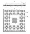
以下、この発明にかかる半導体装置の基板接続構造の実施形態を説明する。図1(a),(b)は、第1の参考形態にかかる半導体装置10を示し、(a)は側面図、(b)は底面図である。半導体装置10は、図示せぬ半導体素子(チップ)を内部に保持するパッケージ(封止体に相当)11と、このパッケージ11の基板接続面11aに接続された多数の放熱用半田バンプ(第1の突起電極に相当)13、および配線接続用半田バンプ(第2の突起電極に相当)14とを備えている。
【0018】
放熱用半田バンプ13は、基板接続面11aの中央領域にまとめて配置され、配線接続用半田バンプ14は、中央領域を囲む周囲領域に配置されている。なお、配線接続用半田バンプ14は、内蔵する半導体素子の電極に接続されて配置されており、半導体素子の回路を外部回路に接続する接点としての機能を有している。
【0019】
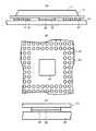
半導体装置10は、基板上に搭載されて熱処理(リフロー)工程を経ることにより、図2(a)に示すように基板20に接続される。基板20には、放熱用半田バンプ13に対応する位置に放熱用パッド21が設けられ、配線接続用バンプ14に対応する位置に配線接続用パッド22が設けられている。半導体装置10は、熱処理工程で各半田バンプを溶融させて各パッドに接合させることにより、基板20に固定される。
【0020】
配線接続用半田バンプ14は、接続用端子としてそれぞれ独立して対応する配線接続用パッド22に接続される必要があり、そのため、熱処理により隣接するバンプ間で半田ブリッジが生じないように所定のピッチで配置されている。一方、放熱用半田バンプ13は、図1に示すように配線接続用半田バンプ14より狭いピッチで形成されている。放熱用半田バンプ13の配置ピッチは、基板20への接合のための熱処理の際に、隣接する半田バンプ間に半田ブリッジが形成され、全ての放熱用半田バンプ13が図2(a)に示すような一体の接合層30を形成するように設定されている。なお、第1の参考形態では、図2(b)に示されるように、放熱用の接合層30が互いに独立して形成された放熱用パッド21上に接続されている。具体的には、例えば各半田バンプの径が0.76mmである場合、放熱用半田バンプ13の配置ピッチは1.00mm、配線接続用半田バンプ14の配置ピッチは1.27mm程度に設定するとよい。
【0021】
上記の構成によれば、実使用時に半導体装置1内の半導体素子で発生した熱は、接合層30を介して基板20側に伝達され、基板20で拡散して放熱される。このとき、半導体装置10から基板20側への熱伝導部が、一体の接合層30により構成されるため、従来のように個々の放熱用半田バンプが独立して基板に接合される場合と比較して、放熱に利用される有効面積の比率が高く、放熱効率を向上させることができる。
【0022】
なお、隣接する放熱用半田バンプどうしを接合し易くするためには、上記の構造において、放熱用パッドの有効面積の当該領域の全面積に対する比率を、配線接続用パッドの有効面積の当該領域の全面積に対する比率より高く設定すればよい。例えば、図3に示すように基板20側にソルダーレジスト層40を形成して各パッドに対応する位置に開口41,42を形成する場合、配線接続用パッド22に対応する開口42を図3(a)に示すように所定の径d1で形成し、放熱用パッド21に対応する開口41を図3(b)に示すようにより大きい径d2で形成する。
【0023】
配線接続用パッド22用の開口42の径、すなわち有効面積比率は、前述のように熱処理により配線接続用半田バンプ14に半田ブリッジが形成されないように決定される。これに対して放熱用パッド21については、その有効面積比率を高くすることにより、積極的に半田ブリッジが形成されるようにしている。このように開口41の径を比較的大きくすることにより、放熱用半田バンプ13の径も大きくすることができ、接合時に半田ブリッジが形成されやすくなる。
【0024】
図4は、第2の参考形態にかかる半導体装置の基板接合構造を示し、(a)は接合状態での側面図、(b)は基板の平面図、(c)は(a)内の破線で囲まれた部分の拡大図である。この例では、半導体装置10側の構成は第1の参考形態と同一であり、基板20の放熱用半田バンプ(接合層30)が接合される領域に、この領域をカバーする連続した平面が放熱用パッド23として形成されている。
【0025】
上記の構成によれば、接合時には溶融して一体とされた接合層30が、放熱用パッド23に全面的に接合される。したがって、接合層30と基板20との間の熱伝導効率を第1の参考形態より高くすることができ、パッケージ内の半導体素子で発生した熱をより効率よく基板20側に伝達させて発散させることができる。
【0026】
図5は、第3の参考形態にかかる半導体装置50を示す断面図である。この例では、パッケージ51の基板接続面51a側に、半導体素子52からの熱を伝達する熱伝導率の高い放熱板53が設けられ、放熱用半田バンプ54をこの放熱板53上に形成している。なお、配線接続用半田バンプ55は、第1の参考形態と同様、周囲領域に形成されている。ワイヤ56は、半導体素子52の電極と、配線接続用バンプ14が設けられるパッケージ51側の電極との間を電気的に接続している。また、放熱用半田バンプ54のピッチが配線接続用半田バンプのピッチより狭い点も第1の参考形態と同様である。
【0027】
第3の参考形態によれば、半導体素子51で発生した熱は放熱板53を介して効率よく放熱用半田バンプ54に伝達される。したがって、半導体装置50を熱処理工程を経て基板に接続し、一体の接合層を形成することにより、第1の参考形態よりも高い放熱効率を得ることができる。
【0028】
図6は、図5に示した第3の参考形態の変形例を示した断面図である。この例では、第3の参考形態の構成に加え、放熱板53に半導体素子51に直接接触する中継部として凸部53aが複数形成されている。この構成によれば、半導体素子51で発生した熱は凸部53aを介して、図5の例より効率よく放熱板53に伝導する。したがって、基板に接続して接合層を形成することにより、第3の参考形態より高い放熱効率を得ることができる。
【0029】
図7は、図5に示した第3の参考形態の他の変形例を示す断面図である。この例では、第3の参考形態の構成に加え、放熱板53に半導体素子51に直接全面的に接触する中継部として平面部53bが形成されている。この構成によれば、図6の例よりさらに放熱板53への熱伝導率を高めることができる。したがって、基板に接続して接合層を形成することにより、図6の構成より高い放熱効率を得ることができる。
【0030】
なお、図7の例のように半導体素子51と放熱板53との間に平面部53bを形成せずに、半導体素子51を直接放熱板53上に直接、またはダイスボンド材を介して接合することもできる。この場合、ダイパッドを放熱板53に兼用することもできる。
【0031】
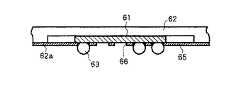
図8は、この発明の第1の実施形態にかかる半導体装置60を示す断面図である。この
例では、半導体素子61がパッケージ62の基板接続面62a側に露出したキャビティダウン構造の半導体装置60を対象としている。放熱用半田バンプ63は、半導体素子61上に直接形成されている。なお、配線接続用半田バンプ64は、第1の参考形態と同様、周囲領域に形成されている。また、放熱用判断バンプ63のピッチが配線接続用半田バンプ64のピッチより狭い点も第1の参考形態と同様である。なお、本発明の第1の実施形態は、第1の参考形態の構成を用いて実施するのみならず、第2の参考形態及び第3の参考形態及びこれらの変形例と同様の構成を用いて実施することもできる。
【0032】
第1の実施形態によれば、半導体素子61で発生した熱は直接放熱用半田バンプ63に伝達されるため、半導体装置60を熱処理工程を経て基板に接続し、一体の接合層を形成することにより、第1の参考形態よりも高い放熱効率を得ることができる。
【0033】
図9は、図8に示した第1の実施形態の変形例を示す側面図であり、半導体素子61が配置された部分を拡大して示している。この例では、半導体素子61の表面を含むパッケージ62の基板接続面62aに、複数の開口を有するソルダーレジスト層65が形成されている。ソルダーレジスト層65の中央領域には、放熱用半田バンプ63を形成するための開口66が複数形成されている。
【0034】
図9のようにソルダーレジスト層65を設けることにより、放熱用半田バンプ63を形成する際に、放熱用半田バンプ63を容易に設計値通りの正確な位置に形成することができる。放熱用半田バンプ63は、基板への接合時に半田ブリッジを形成するよう狭いピッチで形成されるため、半導体装置への搭載時にその形成位置がずれると、隣接する半田バンプが互いに結合する可能性がある。そして、基板への接合前に半田バンプが結合すると、結合した部分は単独の半田バンプより高さが低くなり、基板への接続時に基板に接触しない可能性がある。上述のようにソルダーレジスト層65に形成された開口66を基準に放熱用半田バンプを形成すれば、位置ずれによる半田バンプの不用意な結合を防ぎ、半田バンプの高さを揃えて基板へ接合を確実にすることができる。
【0035】
【発明の効果】
以上説明したように、本発明によれば、基板への接続時に放熱用半田バンプがブリッジを形成して一体の接合層を形成するため、従来のように個々の放熱用半田バンプが独立して基板に接合される場合と比較して、放熱に利用される有効面積の比率が高くなり、放熱効率を向上させることができる。
【図面の簡単な説明】
【図1】第1の参考形態にかかる半導体装置を示し、(a)は側面図、(b)は底面図。
【図2】図1の半導体装置の基板への接続構造を示し、(a)は側面図、(b)は(a)内の破線で囲まれた部分の拡大図。
【図3】第1の参考形態の基板にソルダーレジスト層を設けた構造を示し、(a)は配線接続用パッドを示す断面図、(b)は放熱用パッドを示す断面図。
【図4】第2の参考形態にかかる半導体装置の基板接合構造を示し、(a)は接合状態での側面図、(b)は基板の平面図、(c)は(a)内の破線で囲まれた部分の拡大図。
【図5】第3の参考形態にかかる半導体装置を示す断面図。
【図6】図5に示した第3の参考形態の変形例を示した断面図。
【図7】図5に示した第3の参考形態の他の変形例を示した断面図。
【図8】第1の実施形態にかかる半導体装置を示す断面図。
【図9】図8に示した第1の実施形態の変形例を示す側面図。
【図10】半田バンプを備える従来の半導体装置を示し、(a)は側面図、(b)は底面図。
【図11】図10の半導体装置の基板への接続構造を示す側面図。
【符号の説明】
10 半導体装置
11 パッケージ
13 放熱用半田バンプ
14 配線接続用半田バンプ
20 基板
21 放熱用パッド
22 配線接続用パッド
30 接合層[0001]
TECHNICAL FIELD OF THE INVENTION
The present invention provides a semiconductor device in which a plurality of wiring connection solder bumps and a plurality of heat radiation solder bumps are formed on a substrate connection surface of a package holding a semiconductor element, and a combination of the semiconductor device and the substrate. To a substrate connection structure of a semiconductor device.
[0002]
[Prior art]
10A and 10B show a conventional semiconductor device provided with a solder bump, wherein FIG. 10A is a side view and FIG. 10B is a bottom view. The semiconductor device 1 includes a
[0003]
The heat-dissipating
[0004]
The semiconductor device 1 is mounted on a substrate and undergoes a heat treatment (reflow) process, thereby being connected to the
[0005]
The solder bumps 4 for wiring connection need to be independently connected to the
[0006]
According to the above configuration, the heat generated in the semiconductor element in the package is transmitted to the
[0007]
[Problems to be solved by the invention]
However, in the substrate connection structure using the above-described conventional semiconductor device 1, since the heat conducting portions are formed at the same pitch as the wiring connection solder bumps, the cross-sectional area of the heat conducting portion is relatively small, and the heat radiation efficiency is poor. There is a problem.
[0008]
The present invention has been made in view of the above-described problems of the related art, and provides a semiconductor device capable of improving heat radiation efficiency by a method using a heat radiation solder bump as compared with the related art. An object is to provide a substrate connection structure for a semiconductor device.
[0009]
[Means for Solving the Problems]
In order to achieve the above object, a semiconductor device according to the present invention has a configuration in which a plurality of wiring connection solder bumps and a plurality of heat radiation solder bumps are formed on a substrate connection surface of a package holding a semiconductor element. The heat-dissipating solder bumps are collectively arranged in a partial area of the board connection surface, and during heat treatment for bonding to the board, a solder bridge is formed between adjacent solder bumps to form an integral bonding layer It is characterized by being arranged at a pitch such thatIn addition, the semiconductor element has a cavity-down structure exposed on the substrate connection surface side, and heat-radiating solder bumps are formed directly on the semiconductor element.
[0010]
According to the above configuration, since the heat radiation solder bumps form a bridge when connected to the substrate to form an integral bonding layer, the individual heat radiation solder bumps are independently bonded to the substrate as in the related art. As compared with the case, the ratio of the effective area of the heat conducting portion used for heat dissipation is increased, and the heat dissipation efficiency can be improved.
[0011]
In addition, it is desirable that the heat radiation solder bumps be arranged in a central area of the connection surface, and the wiring connection solder bumps be arranged in a peripheral area surrounding the central area. Since the semiconductor element is usually arranged at the center of the package, the above arrangement allows the heat generated by the semiconductor element to be efficiently radiated to the substrate side via the integral bonding layer.
[0012]
Further, a heat radiating plate having high thermal conductivity for transmitting heat from the semiconductor element may be provided on the substrate connecting surface side of the package, and a heat radiating solder bump may be formed on the heat radiating plate. In this case, if a relay portion that directly contacts the semiconductor element is formed on the heat sink, the heat radiation efficiency can be further improved. When the relay section is arranged so as to substantially entirely contact the surface of the semiconductor element on the heat radiating plate side, maximum heat radiation efficiency can be obtained.
[0013]
Also, to form a solder resist layer having a plurality of openings in the surface of the semiconductor element, formed if so as to form a radiating solder bumps to these openings, the precise location of the solder bump easily design value can do.Further, the pitch between the solder bumps for heat radiation may be narrower than the pitch between the solder bumps for wiring connection. Alternatively, the semiconductor element may be embedded in a groove provided in the package, and the surface of the package opposite to the substrate connection surface may be flattened.
[0014]
On the other hand, the substrate connection structure of the semiconductor device according to the present invention includes a substrate having a wiring connection pad and a heat radiation pad, awiring connection solder bump joined to the wiring connection pad, and a heat radiation solder bump serving as a heat radiation pad. In the combination with theabove-described semiconductor device to be joined , the heat-releasing solder bumps are collectively arranged in a partial area of the board connection surface, and when joined to the board by heat treatment, the solder bumps are placed between the adjacent solder bumps. A bridge is formed to form an integral bonding layer.
[0015]
According to this structure, an integrated heat-dissipating bonding layer is formed between the semiconductor device and the substrate, so that compared to a conventional case in which individual heat-dissipating solder bumps are independently bonded to the substrate. As a result, the ratio of the effective area used for heat dissipation increases, and the heat dissipation efficiency can be improved.
[0016]
In order to make it easy to join adjacent solder bumps for heat dissipation, in the above structure, the ratio of the effective area of the heat dissipation pad to the total area of the area is determined by dividing the effective area of the wiring connection pad by the total area of the area. It is desirable to set higher than the ratio to. In the case where a solder resist layer is formed on the surface of the substrate to which the semiconductor device is bonded, solder bumps for wiring connection and heat dissipation are connected to the solder resist layer to pads for wiring connection and heat dissipation. It is desirable to form an opening for the heat dissipation and design the diameter of the opening formed for heat dissipation to be larger than the diameter of the opening formed for wiring connection. In addition, a continuous plane covering an area to which the heat-dissipating solder bumps are joined may be formed as the heat-dissipating pad.
[0017]
BEST MODE FOR CARRYING OUT THE INVENTION
Hereinafter, an embodiment of a substrate connection structure of a semiconductor device according to the present invention will be described. Figure 1 (a), (b) shows a
[0018]
The heat-dissipating solder bumps 13 are collectively arranged in the central area of the
[0019]
The
[0020]
The wiring connection solder bumps 14 need to be independently connected to the corresponding
[0021]
According to the above configuration, heat generated in the semiconductor element in the semiconductor device 1 during actual use is transmitted to the
[0022]
In order to facilitate bonding of adjacent heat radiation solder bumps, in the above structure, the ratio of the effective area of the heat radiation pad to the total area of the area is determined by dividing the effective area of the wiring connection pad by the area of the area. What is necessary is just to set it higher than the ratio with respect to the whole area. For example, as shown in FIG. 3, when the solder resist
[0023]
The diameter of the
[0024]
4A and 4B show a substrate bonding structure of a semiconductor device according to a secondreference embodiment, wherein FIG. 4A is a side view in a bonded state, FIG. 4B is a plan view of the substrate, and FIG. 4C is a broken line in FIG. It is an enlarged view of the part enclosed with. In this example, the configuration of the
[0025]
According to the above configuration, the
[0026]
Figure 5 is a sectional view showing a
[0027]
According to a thirdreferential embodiment, heat generated in the
[0028]
Figure 6 is a cross-sectional view showing a modification of the thirdreference embodiment shown in FIG. In this example, in addition to the configuration of the thirdreference embodiment, the
[0029]
Figure 7 is a cross-sectional view showing another modified example of the thirdreference embodiment shown in FIG. In this example, in addition to the configuration of the thirdreference embodiment, the
[0030]
Note that the
[0031]
FIG. 8 is a sectional view showing a
[0032]
According to thefirst embodiment, since the heat generated in the
[0033]
FIG. 9 is a side view showing a modification of thefirst embodiment shown in FIG. 8, and shows an enlarged portion where the
[0034]
By providing the solder resist
[0035]
【The invention's effect】
As described above, according to the present invention, when connecting to the substrate, the heat-radiating solder bumps form a bridge to form an integral bonding layer. The ratio of the effective area used for heat dissipation is higher than in the case where the semiconductor device is joined to the substrate, and the heat dissipation efficiency can be improved.
[Brief description of the drawings]
[1] shows a semiconductor device according to the firstreference embodiment, (a) shows the side view, (b) is a bottom view.
2A and 2B show a connection structure of the semiconductor device of FIG. 1 to a substrate, wherein FIG. 2A is a side view, and FIG. 2B is an enlarged view of a portion surrounded by a broken line in FIG.
[3] The first shows the structure in which a solder resist layer on the substrate ofReference Embodiment, (a) shows the cross-sectional view showing a wiring connection pads, (b) is a sectional view showing the heat radiation pad.
4A and 4B show a substrate bonding structure of a semiconductor device according to a secondreference embodiment, wherein FIG. 4A is a side view in a bonded state, FIG. 4B is a plan view of the substrate, and FIG. 4C is a broken line in FIG. Enlarged view of the part surrounded by.
5 is a sectional view showing a semiconductor device according to a thirdreference embodiment.
6 is a sectional view showing a modification of the thirdreference embodiment shown in FIG.
7 is a cross-sectional view showing another modification of the thirdreference embodiment shown in FIG.
FIG. 8 is a sectional view showing the semiconductor device according to thefirst embodiment.
FIG. 9 is a side view showing a modification of thefirst embodiment shown in FIG. 8;
10A and 10B show a conventional semiconductor device having solder bumps, wherein FIG. 10A is a side view, and FIG. 10B is a bottom view.
11 is a side view showing a connection structure of the semiconductor device of FIG. 10 to a substrate.
[Explanation of symbols]
DESCRIPTION OF
Claims (9)
Translated fromJapanese前記半導体素子は、前記パッケージの前記基板接続面側に露出して配置され、前記放熱用半田バンプは、前記半導体素子に直接形成されていることを特徴とする半導体装置。In a semiconductor device in which a plurality of wiring connection solder bumps and a plurality of heat radiation solder bumps are formed on a substrate connection surface of a package holding a semiconductor element, the heat radiation solder bumps are part of the substrate connection surface. Are arranged together in a region, and are arranged at a pitch such that a solder bridge is formed between adjacent solder bumps to form an integral bonding layer during heat treatment for bonding to the substrate,
The semiconductor device, wherein the semiconductor element is disposed so as to be exposed on the substrate connection surface side of the package, and the heat radiation solder bump is directly formed on the semiconductor element.
Priority Applications (4)
| Application Number | Priority Date | Filing Date | Title |
|---|---|---|---|
| JP23212698AJP3602968B2 (en) | 1998-08-18 | 1998-08-18 | Semiconductor device and substrate connection structure thereof |
| US09/376,063US7123480B1 (en) | 1998-08-18 | 1999-08-17 | Package structure for a semiconductor device |
| US09/620,465US6674163B1 (en) | 1998-08-18 | 2000-07-20 | Package structure for a semiconductor device |
| US11/521,554US7514768B2 (en) | 1998-08-18 | 2006-09-15 | Package structure for a semiconductor device incorporating enhanced solder bump structure |
Applications Claiming Priority (1)
| Application Number | Priority Date | Filing Date | Title |
|---|---|---|---|
| JP23212698AJP3602968B2 (en) | 1998-08-18 | 1998-08-18 | Semiconductor device and substrate connection structure thereof |
Related Child Applications (2)
| Application Number | Title | Priority Date | Filing Date |
|---|---|---|---|
| JP2004151586ADivisionJP4225243B2 (en) | 2004-05-21 | 2004-05-21 | Semiconductor device and substrate connection structure |
| JP2004236065ADivisionJP4371946B2 (en) | 2004-08-13 | 2004-08-13 | Semiconductor device and substrate connection structure thereof |
Publications (2)
| Publication Number | Publication Date |
|---|---|
| JP2000068403A JP2000068403A (en) | 2000-03-03 |
| JP3602968B2true JP3602968B2 (en) | 2004-12-15 |
Family
ID=16934418
Family Applications (1)
| Application Number | Title | Priority Date | Filing Date |
|---|---|---|---|
| JP23212698AExpired - Fee RelatedJP3602968B2 (en) | 1998-08-18 | 1998-08-18 | Semiconductor device and substrate connection structure thereof |
Country Status (2)
| Country | Link |
|---|---|
| US (2) | US7123480B1 (en) |
| JP (1) | JP3602968B2 (en) |
Families Citing this family (21)
| Publication number | Priority date | Publication date | Assignee | Title |
|---|---|---|---|---|
| JP3811467B2 (en) | 2003-05-19 | 2006-08-23 | 沖電気工業株式会社 | Semiconductor package |
| SG115753A1 (en) | 2004-03-15 | 2005-10-28 | Yamaha Corp | Semiconductor element and wafer level chip size package therefor |
| JP4556174B2 (en)* | 2004-12-15 | 2010-10-06 | 日本電気株式会社 | Portable terminal device and heat dissipation method |
| US20070158796A1 (en)* | 2005-12-09 | 2007-07-12 | International Rectifier Corporation | Semiconductor package |
| JP2008270728A (en)* | 2007-03-27 | 2008-11-06 | Kyocera Corp | Light emitting device and lighting device |
| TWI343780B (en)* | 2007-12-14 | 2011-06-11 | Delta Electronics Inc | Power module package structure |
| JP2010056162A (en)* | 2008-08-26 | 2010-03-11 | Fujitsu Ltd | Semiconductor device and circuit board assembly |
| US7787252B2 (en)* | 2008-12-04 | 2010-08-31 | Lsi Corporation | Preferentially cooled electronic device |
| US20130026609A1 (en)* | 2010-01-18 | 2013-01-31 | Marvell World Trade Ltd. | Package assembly including a semiconductor substrate with stress relief structure |
| US20110186960A1 (en) | 2010-02-03 | 2011-08-04 | Albert Wu | Techniques and configurations for recessed semiconductor substrates |
| US10431564B2 (en)* | 2014-01-27 | 2019-10-01 | Mediatek Inc. | Structure and formation method of chip package structure |
| US20170053884A1 (en)* | 2015-08-17 | 2017-02-23 | Mediatek Inc. | Structure and layout of ball grid array packages |
| US10177107B2 (en)* | 2016-08-01 | 2019-01-08 | Xilinx, Inc. | Heterogeneous ball pattern package |
| TWI620356B (en)* | 2016-10-07 | 2018-04-01 | 欣興電子股份有限公司 | Package structure and manufacturing method thereof |
| EP3340293A1 (en)* | 2016-12-20 | 2018-06-27 | Siemens Aktiengesellschaft | Semiconductor module with support structure on the bottom |
| JP6719400B2 (en)* | 2017-02-14 | 2020-07-08 | 三菱電機株式会社 | Semiconductor package |
| KR102269743B1 (en)* | 2019-03-05 | 2021-06-25 | 매그나칩 반도체 유한회사 | Semiconductor Package Including Inner Lead Pattern Group |
| KR102741172B1 (en)* | 2019-12-06 | 2024-12-11 | 삼성전자주식회사 | Semiconductor package comprising test bumps |
| KR102704716B1 (en) | 2020-02-26 | 2024-09-10 | 삼성전자주식회사 | Semiconductor package and method of manufacturing the same |
| KR102746861B1 (en) | 2020-04-24 | 2024-12-27 | 삼성전자주식회사 | Semiconductor package |
| CN112038320A (en)* | 2020-08-05 | 2020-12-04 | 厦门通富微电子有限公司 | Substrate and flip chip packaging structure |
Family Cites Families (52)
| Publication number | Priority date | Publication date | Assignee | Title |
|---|---|---|---|---|
| US4460537A (en) | 1982-07-26 | 1984-07-17 | Motorola, Inc. | Slot transfer molding apparatus and methods |
| DE3780764T2 (en)* | 1986-11-15 | 1992-12-24 | Matsushita Electric Works Ltd | MOLDED PLASTIC CHIP HOUSING WITH PLUG PATTERN. |
| FR2625038B1 (en)* | 1987-12-22 | 1990-08-17 | Cit Alcatel | METHOD AND DEVICE FOR COOLING AN INTEGRATED CIRCUIT HOUSING |
| US5011066A (en)* | 1990-07-27 | 1991-04-30 | Motorola, Inc. | Enhanced collapse solder interconnection |
| US5132778A (en) | 1990-09-17 | 1992-07-21 | Motorola, Inc. | Transfer molding compound |
| US5136366A (en) | 1990-11-05 | 1992-08-04 | Motorola, Inc. | Overmolded semiconductor package with anchoring means |
| US5216278A (en)* | 1990-12-04 | 1993-06-01 | Motorola, Inc. | Semiconductor device having a pad array carrier package |
| US5153385A (en) | 1991-03-18 | 1992-10-06 | Motorola, Inc. | Transfer molded semiconductor package with improved adhesion |
| US5285352A (en)* | 1992-07-15 | 1994-02-08 | Motorola, Inc. | Pad array semiconductor device with thermal conductor and process for making the same |
| US5729894A (en)* | 1992-07-21 | 1998-03-24 | Lsi Logic Corporation | Method of assembling ball bump grid array semiconductor packages |
| US5592025A (en) | 1992-08-06 | 1997-01-07 | Motorola, Inc. | Pad array semiconductor device |
| US5490324A (en)* | 1993-09-15 | 1996-02-13 | Lsi Logic Corporation | Method of making integrated circuit package having multiple bonding tiers |
| US5642261A (en)* | 1993-12-20 | 1997-06-24 | Sgs-Thomson Microelectronics, Inc. | Ball-grid-array integrated circuit package with solder-connected thermal conductor |
| US5506756A (en)* | 1994-01-25 | 1996-04-09 | Intel Corporation | Tape BGA package die-up/die down |
| JPH07335784A (en)* | 1994-06-03 | 1995-12-22 | Dainippon Printing Co Ltd | Surface mount semiconductor device and manufacturing method thereof |
| US5741729A (en)* | 1994-07-11 | 1998-04-21 | Sun Microsystems, Inc. | Ball grid array package for an integrated circuit |
| JP3104537B2 (en) | 1994-08-30 | 2000-10-30 | 松下電器産業株式会社 | Electronic components |
| JPH0897322A (en) | 1994-09-22 | 1996-04-12 | Oki Electric Ind Co Ltd | Semiconductor package |
| JP3599121B2 (en)* | 1994-10-31 | 2004-12-08 | 京セラ株式会社 | Imaging device |
| KR0159987B1 (en)* | 1995-07-05 | 1998-12-01 | 아남산업주식회사 | Heat dissipation structure of ball grid array (BGA) semiconductor packages using solder balls as input / output terminals |
| JP2830903B2 (en)* | 1995-07-21 | 1998-12-02 | 日本電気株式会社 | Method for manufacturing semiconductor device |
| JP3123638B2 (en)* | 1995-09-25 | 2001-01-15 | 株式会社三井ハイテック | Semiconductor device |
| US5616888A (en)* | 1995-09-29 | 1997-04-01 | Allen-Bradley Company, Inc. | Rigid-flex circuit board having a window for an insulated mounting area |
| US5767575A (en)* | 1995-10-17 | 1998-06-16 | Prolinx Labs Corporation | Ball grid array structure and method for packaging an integrated circuit chip |
| US6046499A (en)* | 1996-03-27 | 2000-04-04 | Kabushiki Kaisha Toshiba | Heat transfer configuration for a semiconductor device |
| MY123146A (en)* | 1996-03-28 | 2006-05-31 | Intel Corp | Perimeter matrix ball grid array circuit package with a populated center |
| JP2817712B2 (en)* | 1996-05-24 | 1998-10-30 | 日本電気株式会社 | Semiconductor device and mounting method thereof |
| JP2842378B2 (en)* | 1996-05-31 | 1999-01-06 | 日本電気株式会社 | High-density mounting structure for electronic circuit boards |
| JP2959480B2 (en)* | 1996-08-12 | 1999-10-06 | 日本電気株式会社 | Semiconductor device and manufacturing method thereof |
| US5909058A (en)* | 1996-09-25 | 1999-06-01 | Kabushiki Kaisha Toshiba | Semiconductor package and semiconductor mounting part |
| US5708566A (en)* | 1996-10-31 | 1998-01-13 | Motorola, Inc. | Solder bonded electronic module |
| JP2975979B2 (en)* | 1996-12-30 | 1999-11-10 | アナムインダストリアル株式会社 | Flexible circuit board for ball grid array semiconductor package |
| JP3378771B2 (en)* | 1997-05-30 | 2003-02-17 | 株式会社三井ハイテック | Semiconductor device manufacturing equipment |
| KR20010023027A (en)* | 1997-08-19 | 2001-03-26 | 가나이 쓰토무 | Method for forming bump electrode and method for manufacturing semiconductor device |
| JPH1174407A (en)* | 1997-08-29 | 1999-03-16 | Mitsubishi Electric Corp | Semiconductor device |
| KR100309957B1 (en)* | 1997-09-08 | 2002-08-21 | 신꼬오덴기 고교 가부시키가이샤 | Semiconductor device |
| US6294407B1 (en)* | 1998-05-06 | 2001-09-25 | Virtual Integration, Inc. | Microelectronic packages including thin film decal and dielectric adhesive layer having conductive vias therein, and methods of fabricating the same |
| US6194782B1 (en)* | 1998-06-24 | 2001-02-27 | Nortel Networks Limited | Mechanically-stabilized area-array device package |
| US6133634A (en)* | 1998-08-05 | 2000-10-17 | Fairchild Semiconductor Corporation | High performance flip chip package |
| US6674163B1 (en)* | 1998-08-18 | 2004-01-06 | Oki Electric Industry Co., Ltd. | Package structure for a semiconductor device |
| US6057596A (en)* | 1998-10-19 | 2000-05-02 | Silicon Integrated Systems Corp. | Chip carrier having a specific power join distribution structure |
| TW410446B (en)* | 1999-01-21 | 2000-11-01 | Siliconware Precision Industries Co Ltd | BGA semiconductor package |
| US6219254B1 (en)* | 1999-04-05 | 2001-04-17 | Trw Inc. | Chip-to-board connection assembly and method therefor |
| TW413874B (en)* | 1999-04-12 | 2000-12-01 | Siliconware Precision Industries Co Ltd | BGA semiconductor package having exposed heat dissipation layer and its manufacturing method |
| US6268568B1 (en)* | 1999-05-04 | 2001-07-31 | Anam Semiconductor, Inc. | Printed circuit board with oval solder ball lands for BGA semiconductor packages |
| US6790710B2 (en)* | 2002-01-31 | 2004-09-14 | Asat Limited | Method of manufacturing an integrated circuit package |
| US6631078B2 (en)* | 2002-01-10 | 2003-10-07 | International Business Machines Corporation | Electronic package with thermally conductive standoff |
| US6650015B2 (en)* | 2002-02-05 | 2003-11-18 | Siliconware Precision Industries Co., Ltd. | Cavity-down ball grid array package with semiconductor chip solder ball |
| US6659512B1 (en)* | 2002-07-18 | 2003-12-09 | Hewlett-Packard Development Company, L.P. | Integrated circuit package employing flip-chip technology and method of assembly |
| TW582106B (en)* | 2003-02-19 | 2004-04-01 | Advanced Semiconductor Eng | Package and manufacturing method thereof |
| US7038311B2 (en)* | 2003-12-18 | 2006-05-02 | Texas Instruments Incorporated | Thermally enhanced semiconductor package |
| KR100618892B1 (en)* | 2005-04-13 | 2006-09-01 | 삼성전자주식회사 | Semiconductor package achieves fan-out structure through wire bonding |
- 1998
- 1998-08-18JPJP23212698Apatent/JP3602968B2/ennot_activeExpired - Fee Related
- 1999
- 1999-08-17USUS09/376,063patent/US7123480B1/ennot_activeExpired - Lifetime
- 2006
- 2006-09-15USUS11/521,554patent/US7514768B2/ennot_activeExpired - Fee Related
Also Published As
| Publication number | Publication date |
|---|---|
| US7123480B1 (en) | 2006-10-17 |
| JP2000068403A (en) | 2000-03-03 |
| US20070008704A1 (en) | 2007-01-11 |
| US7514768B2 (en) | 2009-04-07 |
Similar Documents
| Publication | Publication Date | Title |
|---|---|---|
| JP3602968B2 (en) | Semiconductor device and substrate connection structure thereof | |
| US6858919B2 (en) | Semiconductor package | |
| JP5247281B2 (en) | Peripheral matrix ball grid array circuit package with distributed center | |
| US8330264B2 (en) | Packaging configurations for vertical electronic devices using conductive traces disposed on laminated board layers | |
| JP2002353398A (en) | Semiconductor device | |
| JPH0964099A (en) | Semiconductor device and its mounting structure | |
| JPH10233509A (en) | Semiconductor power devices | |
| US6501160B1 (en) | Semiconductor device and a method of manufacturing the same and a mount structure | |
| JP2829925B2 (en) | Semiconductor package and electronic circuit board | |
| KR102359904B1 (en) | Semiconductor package | |
| JP3421137B2 (en) | Bare chip mounting structure and heat sink | |
| JPH09326450A (en) | Semiconductor device and manufacturing method thereof | |
| US6674163B1 (en) | Package structure for a semiconductor device | |
| JP4225243B2 (en) | Semiconductor device and substrate connection structure | |
| JP4371946B2 (en) | Semiconductor device and substrate connection structure thereof | |
| US6291893B1 (en) | Power semiconductor device for “flip-chip” connections | |
| JP2000188359A (en) | Semiconductor package | |
| JP3348562B2 (en) | Semiconductor package mounting structure | |
| JP4300432B2 (en) | Electronic component and manufacturing method thereof | |
| JP3676590B2 (en) | Semiconductor device | |
| JP4189681B2 (en) | Electronic component, semiconductor device, and manufacturing method thereof | |
| JP2746248B2 (en) | Chip carrier and method of soldering chip carrier | |
| JP2004247669A (en) | Semiconductor device mounting structure | |
| JP2004103724A (en) | Semiconductor device and semiconductor device mounting structure | |
| JPH05166980A (en) | Semiconductor device |
Legal Events
| Date | Code | Title | Description |
|---|---|---|---|
| A977 | Report on retrieval | Free format text:JAPANESE INTERMEDIATE CODE: A971007 Effective date:20040130 | |
| A131 | Notification of reasons for refusal | Free format text:JAPANESE INTERMEDIATE CODE: A131 Effective date:20040331 | |
| A521 | Request for written amendment filed | Free format text:JAPANESE INTERMEDIATE CODE: A523 Effective date:20040524 | |
| A131 | Notification of reasons for refusal | Free format text:JAPANESE INTERMEDIATE CODE: A131 Effective date:20040622 | |
| A521 | Request for written amendment filed | Free format text:JAPANESE INTERMEDIATE CODE: A523 Effective date:20040813 | |
| TRDD | Decision of grant or rejection written | ||
| A01 | Written decision to grant a patent or to grant a registration (utility model) | Free format text:JAPANESE INTERMEDIATE CODE: A01 Effective date:20040907 | |
| A61 | First payment of annual fees (during grant procedure) | Free format text:JAPANESE INTERMEDIATE CODE: A61 Effective date:20040927 | |
| R150 | Certificate of patent or registration of utility model | Free format text:JAPANESE INTERMEDIATE CODE: R150 | |
| FPAY | Renewal fee payment (event date is renewal date of database) | Free format text:PAYMENT UNTIL: 20081001 Year of fee payment:4 | |
| FPAY | Renewal fee payment (event date is renewal date of database) | Free format text:PAYMENT UNTIL: 20081001 Year of fee payment:4 | |
| FPAY | Renewal fee payment (event date is renewal date of database) | Free format text:PAYMENT UNTIL: 20091001 Year of fee payment:5 | |
| S111 | Request for change of ownership or part of ownership | Free format text:JAPANESE INTERMEDIATE CODE: R313111 | |
| S531 | Written request for registration of change of domicile | Free format text:JAPANESE INTERMEDIATE CODE: R313531 | |
| FPAY | Renewal fee payment (event date is renewal date of database) | Free format text:PAYMENT UNTIL: 20091001 Year of fee payment:5 | |
| R350 | Written notification of registration of transfer | Free format text:JAPANESE INTERMEDIATE CODE: R350 | |
| FPAY | Renewal fee payment (event date is renewal date of database) | Free format text:PAYMENT UNTIL: 20091001 Year of fee payment:5 | |
| FPAY | Renewal fee payment (event date is renewal date of database) | Free format text:PAYMENT UNTIL: 20101001 Year of fee payment:6 | |
| FPAY | Renewal fee payment (event date is renewal date of database) | Free format text:PAYMENT UNTIL: 20101001 Year of fee payment:6 | |
| FPAY | Renewal fee payment (event date is renewal date of database) | Free format text:PAYMENT UNTIL: 20111001 Year of fee payment:7 | |
| FPAY | Renewal fee payment (event date is renewal date of database) | Free format text:PAYMENT UNTIL: 20121001 Year of fee payment:8 | |
| FPAY | Renewal fee payment (event date is renewal date of database) | Free format text:PAYMENT UNTIL: 20121001 Year of fee payment:8 | |
| S533 | Written request for registration of change of name | Free format text:JAPANESE INTERMEDIATE CODE: R313533 | |
| FPAY | Renewal fee payment (event date is renewal date of database) | Free format text:PAYMENT UNTIL: 20121001 Year of fee payment:8 | |
| R350 | Written notification of registration of transfer | Free format text:JAPANESE INTERMEDIATE CODE: R350 | |
| FPAY | Renewal fee payment (event date is renewal date of database) | Free format text:PAYMENT UNTIL: 20131001 Year of fee payment:9 | |
| S531 | Written request for registration of change of domicile | Free format text:JAPANESE INTERMEDIATE CODE: R313531 | |
| R350 | Written notification of registration of transfer | Free format text:JAPANESE INTERMEDIATE CODE: R350 | |
| LAPS | Cancellation because of no payment of annual fees |