JP3599324B2 - Continuous feed parallel reactor - Google Patents
Continuous feed parallel reactorDownload PDFInfo
- Publication number
- JP3599324B2 JP3599324B2JP2000584989AJP2000584989AJP3599324B2JP 3599324 B2JP3599324 B2JP 3599324B2JP 2000584989 AJP2000584989 AJP 2000584989AJP 2000584989 AJP2000584989 AJP 2000584989AJP 3599324 B2JP3599324 B2JP 3599324B2
- Authority
- JP
- Japan
- Prior art keywords
- reactor
- header
- continuous
- reaction
- block
- Prior art date
- Legal status (The legal status is an assumption and is not a legal conclusion. Google has not performed a legal analysis and makes no representation as to the accuracy of the status listed.)
- Expired - Fee Related
Links
Images


Classifications
- B—PERFORMING OPERATIONS; TRANSPORTING
- B01—PHYSICAL OR CHEMICAL PROCESSES OR APPARATUS IN GENERAL
- B01J—CHEMICAL OR PHYSICAL PROCESSES, e.g. CATALYSIS OR COLLOID CHEMISTRY; THEIR RELEVANT APPARATUS
- B01J19/00—Chemical, physical or physico-chemical processes in general; Their relevant apparatus
- B01J19/0046—Sequential or parallel reactions, e.g. for the synthesis of polypeptides or polynucleotides; Apparatus and devices for combinatorial chemistry or for making molecular arrays
- B—PERFORMING OPERATIONS; TRANSPORTING
- B01—PHYSICAL OR CHEMICAL PROCESSES OR APPARATUS IN GENERAL
- B01J—CHEMICAL OR PHYSICAL PROCESSES, e.g. CATALYSIS OR COLLOID CHEMISTRY; THEIR RELEVANT APPARATUS
- B01J2219/00—Chemical, physical or physico-chemical processes in general; Their relevant apparatus
- B01J2219/00274—Sequential or parallel reactions; Apparatus and devices for combinatorial chemistry or for making arrays; Chemical library technology
- B01J2219/00277—Apparatus
- B01J2219/00279—Features relating to reactor vessels
- B01J2219/00281—Individual reactor vessels
- B01J2219/00286—Reactor vessels with top and bottom openings
- B01J2219/00288—Reactor vessels with top and bottom openings in the shape of syringes
- B01J2219/0029—Reactor vessels with top and bottom openings in the shape of syringes with pistons or plungers
- B—PERFORMING OPERATIONS; TRANSPORTING
- B01—PHYSICAL OR CHEMICAL PROCESSES OR APPARATUS IN GENERAL
- B01J—CHEMICAL OR PHYSICAL PROCESSES, e.g. CATALYSIS OR COLLOID CHEMISTRY; THEIR RELEVANT APPARATUS
- B01J2219/00—Chemical, physical or physico-chemical processes in general; Their relevant apparatus
- B01J2219/00274—Sequential or parallel reactions; Apparatus and devices for combinatorial chemistry or for making arrays; Chemical library technology
- B01J2219/00277—Apparatus
- B01J2219/00279—Features relating to reactor vessels
- B01J2219/00306—Reactor vessels in a multiple arrangement
- B01J2219/00308—Reactor vessels in a multiple arrangement interchangeably mounted in racks or blocks
- B01J2219/0031—Reactor vessels in a multiple arrangement interchangeably mounted in racks or blocks the racks or blocks being mounted in stacked arrangements
- B—PERFORMING OPERATIONS; TRANSPORTING
- B01—PHYSICAL OR CHEMICAL PROCESSES OR APPARATUS IN GENERAL
- B01J—CHEMICAL OR PHYSICAL PROCESSES, e.g. CATALYSIS OR COLLOID CHEMISTRY; THEIR RELEVANT APPARATUS
- B01J2219/00—Chemical, physical or physico-chemical processes in general; Their relevant apparatus
- B01J2219/00274—Sequential or parallel reactions; Apparatus and devices for combinatorial chemistry or for making arrays; Chemical library technology
- B01J2219/00277—Apparatus
- B01J2219/00279—Features relating to reactor vessels
- B01J2219/00306—Reactor vessels in a multiple arrangement
- B01J2219/00313—Reactor vessels in a multiple arrangement the reactor vessels being formed by arrays of wells in blocks
- B01J2219/00315—Microtiter plates
- B—PERFORMING OPERATIONS; TRANSPORTING
- B01—PHYSICAL OR CHEMICAL PROCESSES OR APPARATUS IN GENERAL
- B01J—CHEMICAL OR PHYSICAL PROCESSES, e.g. CATALYSIS OR COLLOID CHEMISTRY; THEIR RELEVANT APPARATUS
- B01J2219/00—Chemical, physical or physico-chemical processes in general; Their relevant apparatus
- B01J2219/00274—Sequential or parallel reactions; Apparatus and devices for combinatorial chemistry or for making arrays; Chemical library technology
- B01J2219/00277—Apparatus
- B01J2219/00279—Features relating to reactor vessels
- B01J2219/00306—Reactor vessels in a multiple arrangement
- B01J2219/00313—Reactor vessels in a multiple arrangement the reactor vessels being formed by arrays of wells in blocks
- B01J2219/00319—Reactor vessels in a multiple arrangement the reactor vessels being formed by arrays of wells in blocks the blocks being mounted in stacked arrangements
- B—PERFORMING OPERATIONS; TRANSPORTING
- B01—PHYSICAL OR CHEMICAL PROCESSES OR APPARATUS IN GENERAL
- B01J—CHEMICAL OR PHYSICAL PROCESSES, e.g. CATALYSIS OR COLLOID CHEMISTRY; THEIR RELEVANT APPARATUS
- B01J2219/00—Chemical, physical or physico-chemical processes in general; Their relevant apparatus
- B01J2219/00274—Sequential or parallel reactions; Apparatus and devices for combinatorial chemistry or for making arrays; Chemical library technology
- B01J2219/00277—Apparatus
- B01J2219/00351—Means for dispensing and evacuation of reagents
- B—PERFORMING OPERATIONS; TRANSPORTING
- B01—PHYSICAL OR CHEMICAL PROCESSES OR APPARATUS IN GENERAL
- B01J—CHEMICAL OR PHYSICAL PROCESSES, e.g. CATALYSIS OR COLLOID CHEMISTRY; THEIR RELEVANT APPARATUS
- B01J2219/00—Chemical, physical or physico-chemical processes in general; Their relevant apparatus
- B01J2219/00274—Sequential or parallel reactions; Apparatus and devices for combinatorial chemistry or for making arrays; Chemical library technology
- B01J2219/00277—Apparatus
- B01J2219/00479—Means for mixing reactants or products in the reaction vessels
- B01J2219/00481—Means for mixing reactants or products in the reaction vessels by the use of moving stirrers within the reaction vessels
- B—PERFORMING OPERATIONS; TRANSPORTING
- B01—PHYSICAL OR CHEMICAL PROCESSES OR APPARATUS IN GENERAL
- B01J—CHEMICAL OR PHYSICAL PROCESSES, e.g. CATALYSIS OR COLLOID CHEMISTRY; THEIR RELEVANT APPARATUS
- B01J2219/00—Chemical, physical or physico-chemical processes in general; Their relevant apparatus
- B01J2219/00274—Sequential or parallel reactions; Apparatus and devices for combinatorial chemistry or for making arrays; Chemical library technology
- B01J2219/00277—Apparatus
- B01J2219/00479—Means for mixing reactants or products in the reaction vessels
- B01J2219/00484—Means for mixing reactants or products in the reaction vessels by shaking, vibrating or oscillating of the reaction vessels
- B—PERFORMING OPERATIONS; TRANSPORTING
- B01—PHYSICAL OR CHEMICAL PROCESSES OR APPARATUS IN GENERAL
- B01J—CHEMICAL OR PHYSICAL PROCESSES, e.g. CATALYSIS OR COLLOID CHEMISTRY; THEIR RELEVANT APPARATUS
- B01J2219/00—Chemical, physical or physico-chemical processes in general; Their relevant apparatus
- B01J2219/00274—Sequential or parallel reactions; Apparatus and devices for combinatorial chemistry or for making arrays; Chemical library technology
- B01J2219/00277—Apparatus
- B01J2219/00495—Means for heating or cooling the reaction vessels
- B—PERFORMING OPERATIONS; TRANSPORTING
- B01—PHYSICAL OR CHEMICAL PROCESSES OR APPARATUS IN GENERAL
- B01J—CHEMICAL OR PHYSICAL PROCESSES, e.g. CATALYSIS OR COLLOID CHEMISTRY; THEIR RELEVANT APPARATUS
- B01J2219/00—Chemical, physical or physico-chemical processes in general; Their relevant apparatus
- B01J2219/00274—Sequential or parallel reactions; Apparatus and devices for combinatorial chemistry or for making arrays; Chemical library technology
- B01J2219/00583—Features relative to the processes being carried out
- B01J2219/00585—Parallel processes
- B—PERFORMING OPERATIONS; TRANSPORTING
- B01—PHYSICAL OR CHEMICAL PROCESSES OR APPARATUS IN GENERAL
- B01J—CHEMICAL OR PHYSICAL PROCESSES, e.g. CATALYSIS OR COLLOID CHEMISTRY; THEIR RELEVANT APPARATUS
- B01J2219/00—Chemical, physical or physico-chemical processes in general; Their relevant apparatus
- B01J2219/00274—Sequential or parallel reactions; Apparatus and devices for combinatorial chemistry or for making arrays; Chemical library technology
- B01J2219/0068—Means for controlling the apparatus of the process
- B01J2219/00686—Automatic
- B01J2219/00691—Automatic using robots
- B—PERFORMING OPERATIONS; TRANSPORTING
- B01—PHYSICAL OR CHEMICAL PROCESSES OR APPARATUS IN GENERAL
- B01J—CHEMICAL OR PHYSICAL PROCESSES, e.g. CATALYSIS OR COLLOID CHEMISTRY; THEIR RELEVANT APPARATUS
- B01J2219/00—Chemical, physical or physico-chemical processes in general; Their relevant apparatus
- B01J2219/00274—Sequential or parallel reactions; Apparatus and devices for combinatorial chemistry or for making arrays; Chemical library technology
- B01J2219/00718—Type of compounds synthesised
- B01J2219/0072—Organic compounds
- B01J2219/00722—Nucleotides
- C—CHEMISTRY; METALLURGY
- C40—COMBINATORIAL TECHNOLOGY
- C40B—COMBINATORIAL CHEMISTRY; LIBRARIES, e.g. CHEMICAL LIBRARIES
- C40B40/00—Libraries per se, e.g. arrays, mixtures
- C40B40/04—Libraries containing only organic compounds
- C40B40/14—Libraries containing macromolecular compounds and not covered by groups C40B40/06 - C40B40/12
- C—CHEMISTRY; METALLURGY
- C40—COMBINATORIAL TECHNOLOGY
- C40B—COMBINATORIAL CHEMISTRY; LIBRARIES, e.g. CHEMICAL LIBRARIES
- C40B60/00—Apparatus specially adapted for use in combinatorial chemistry or with libraries
- C40B60/14—Apparatus specially adapted for use in combinatorial chemistry or with libraries for creating libraries
- Y—GENERAL TAGGING OF NEW TECHNOLOGICAL DEVELOPMENTS; GENERAL TAGGING OF CROSS-SECTIONAL TECHNOLOGIES SPANNING OVER SEVERAL SECTIONS OF THE IPC; TECHNICAL SUBJECTS COVERED BY FORMER USPC CROSS-REFERENCE ART COLLECTIONS [XRACs] AND DIGESTS
- Y10—TECHNICAL SUBJECTS COVERED BY FORMER USPC
- Y10S—TECHNICAL SUBJECTS COVERED BY FORMER USPC CROSS-REFERENCE ART COLLECTIONS [XRACs] AND DIGESTS
- Y10S526/00—Synthetic resins or natural rubbers -- part of the class 520 series
- Y10S526/92—Apparatus for use in addition polymerization processes
- Y—GENERAL TAGGING OF NEW TECHNOLOGICAL DEVELOPMENTS; GENERAL TAGGING OF CROSS-SECTIONAL TECHNOLOGIES SPANNING OVER SEVERAL SECTIONS OF THE IPC; TECHNICAL SUBJECTS COVERED BY FORMER USPC CROSS-REFERENCE ART COLLECTIONS [XRACs] AND DIGESTS
- Y10—TECHNICAL SUBJECTS COVERED BY FORMER USPC
- Y10T—TECHNICAL SUBJECTS COVERED BY FORMER US CLASSIFICATION
- Y10T436/00—Chemistry: analytical and immunological testing
- Y10T436/11—Automated chemical analysis
- Y—GENERAL TAGGING OF NEW TECHNOLOGICAL DEVELOPMENTS; GENERAL TAGGING OF CROSS-SECTIONAL TECHNOLOGIES SPANNING OVER SEVERAL SECTIONS OF THE IPC; TECHNICAL SUBJECTS COVERED BY FORMER USPC CROSS-REFERENCE ART COLLECTIONS [XRACs] AND DIGESTS
- Y10—TECHNICAL SUBJECTS COVERED BY FORMER USPC
- Y10T—TECHNICAL SUBJECTS COVERED BY FORMER US CLASSIFICATION
- Y10T436/00—Chemistry: analytical and immunological testing
- Y10T436/25—Chemistry: analytical and immunological testing including sample preparation
- Y10T436/25625—Dilution
- Y—GENERAL TAGGING OF NEW TECHNOLOGICAL DEVELOPMENTS; GENERAL TAGGING OF CROSS-SECTIONAL TECHNOLOGIES SPANNING OVER SEVERAL SECTIONS OF THE IPC; TECHNICAL SUBJECTS COVERED BY FORMER USPC CROSS-REFERENCE ART COLLECTIONS [XRACs] AND DIGESTS
- Y10—TECHNICAL SUBJECTS COVERED BY FORMER USPC
- Y10T—TECHNICAL SUBJECTS COVERED BY FORMER US CLASSIFICATION
- Y10T436/00—Chemistry: analytical and immunological testing
- Y10T436/25—Chemistry: analytical and immunological testing including sample preparation
- Y10T436/2575—Volumetric liquid transfer
Landscapes
- Chemical & Material Sciences (AREA)
- Organic Chemistry (AREA)
- Chemical Kinetics & Catalysis (AREA)
- Physical Or Chemical Processes And Apparatus (AREA)
- Automatic Analysis And Handling Materials Therefor (AREA)
- Feeding, Discharge, Calcimining, Fusing, And Gas-Generation Devices (AREA)
Description
Translated fromJapanese【0001】
【発明の属する技術分野】
本発明は、プロセス条件が制御され、モニタされる材料の配列を迅速に作成し、スクリーニングし、特性評価するための方法及び装置、特に、それぞれの反応器へのフィードが連続的に行われるものに関する。
【0002】
【従来の技術】
組合せ(コンビネトリアル、Combinetorial)材料科学は、一般的に、相対的に少ない組の前駆物質を使用して、種々の化合物あるいは材料の集合体を形成する方法及び/又は、望ましい実用上の特徴と特性とに関して、化合物あるいは材料の集合体を迅速に試験あるいはスクリーニングする方法を参照する。現在行われているように、組合せ材料科学は、科学者が、候補物質を生成し、評価する速度を劇的に速めることにより、候補物質の構造的バリエーションの影響を体系的に検討することを許容する。従来の発見方法と比較して、組合せ手法は、それぞれの候補物質を調製し、スクリーニングすることに関するコストを明確に低減する。
【0003】
組合せ化学は、薬の発見プロセスに革命を起こした。例えば、Acc.Chem.Res.p1−p170,vol29(1996)、Chem.Rev.p349−p509,vol97(1997)、S.Borman著、Chem.Eng.News p43−p62(1997年2月24日)、A.M.Thayer著、Chem.Eng.News p57−p64(1996年2月12日)、N.Terret著、Drug Discovery Today,p402,vol1(1996)を参照する。薬の発見は、2つのステップから成るプロセスであると認識される。即ち、研究室的合成あるいは天然物の収集により、候補化合物を取得し、次いで、効験(効能)に関して、評価あるいはスクリーニングする。製薬研究者は、天然物と、長年合成され、カタログ化された化合物のライブラリとの治療的な値を迅速に評価するために、長い間、高スループット(時間処理量)スクリーニング(HTS、High Throughput Screening)プロトコルを使用してきた。しかし、HTSプロトコルと比較して、化学的合成は、歴史的に、ゆっくりとした、工数のかかるプロセスである。組合せ手法の出現で、科学者は、現在では、HTSプロトコルと同様なペースで、有機分子の大きなライブラリを作成できる。
【0004】
近時、組合せアプローチは、薬とは関係ない発見プログラムに使用されている。例えば、ある科学者たちは、組合せ戦術は、高温超伝導体、磁気抵抗材料、蛍光材料及び触媒材料のような、無機化合物の発見にも希望を提供することを認識している。例えば、それぞれここで、参照により引用される、米国出願08/327513号、「著名材料の組合せ合成」(公開WO96/11878)、米国出願08/898715号、「有機化合物と触媒との組合せ合成と分析」(公開WO98/03251)と同様に、米国特許5776359号を参照する。
【0005】
薬の発見における合成上のボトルネックを取り除くことに成功したので、多くの研究者は、組合せ手法を、構造的多様性を作成するための道具として、狭義に捉えるに至った。合成中に、温度、圧力及び他のプロセス条件の変化が、ライブラリ要素の特性に強く影響する可能性があることを指摘する科学者は、ほとんどいない。例えば、異なる反応条件あるいは濃度の下で、それらの生成物に与える影響を決定するために1組の成分が組合せて使用される、フォーミュレーション化学において、反応条件は、特に重要である。さらに、多くの作業者が、ライブラリ要素の1つを識別するために(工業)プロセスが使用され得ることを実感しないように、製薬研究におけるより異なった工業プロセスを模倣することは、しばしば有益である。いくつかの並列反応装置が知られ、例えば、それぞれこここで参照により引用される、WO98/36826号、米国特許4099923号、米国特許4944923号を参照する。しかし、必要とされることは、工業プロセスを伴い得る組合せライブラリを調製し、スクリーニングするための装置である。
【0006】
【発明が解決しようとする課題】
本発明は、1以上の反応物を、一定時間、1以上のソースから複数の反応器に連続的に供給して、複数の異なる混合物を並列的に反応させるための方法及び装置を提供する。本発明は、1以上の試薬を1のソースあるいはヘッダ容器から反応器に供給する、準連続プロセス用の方法及び装置を提供する。本発明は、さらに、試薬が反応器に供給されると同時に、生成物を反応器から除去する、連続プロセス用の方法及び装置を提供する。
【0007】
広く言えば、それぞれの反応は、1つの反応器内に含まれ、複数の反応器が、追加的に、単一の並列反応器ブロックに結合される。反応器に供給される1以上の反応物を提供する1以上の反応物ソース(「ヘッダバレル」と呼ぶ)が、それぞれの反応器と関連する。複数のソースまたはヘッダバレルは、1のヘッダブロックに提供され得る。ヘッダバレルは、移送ラインを介して、反応容器に接続される。移送システムは、移送ラインを介して、ヘッダバレルから反応器に反応物を供給し、追加的に、その一方で、反応器の内容物が混合される。移送システムは、ポンプあるいはプランジャーから構成されても良い。反応容器は、典型的には、移送ラインとの接続部を除いて、外部から密閉(シール)され、シール方法が提供される。ある実施例においては、全体システムは、反応器、ヘッダ、プランジャー及び駆動システムが、空気及び湿度に敏感な反応には適している、不活性雰囲気のグローブボックスに保持されることを許容する寸法である。
【0008】
さらに特定の実施例では、96セルの準連続並列反応ブロックが提供される。理想的には、それぞれの容器は、標準の微小滴定(Microtiter)プレート間隔で配置される。別体のヘッダバレルは、それぞれの反応器に対して使用され、96のヘッダバレルは、1のヘッダブロック内に配置される。反応ブロック内の反応器は、廃棄可能なガラス瓶であり、反応ブロック内のヘッダバレルは、ガラス製シリンジである。これらのブロック及び反応器は、移送ラインであり、またバレルから容器を断熱し、2つの容器の内容物の望ましくない混合を抑制する作用を有する不活性オリフィスに接続される。この特定の実施例では、反応器は、一定の容積であり、初期には、部分的にのみ液体で充填され、容器内に、圧縮可能な気体のヘッドスペースを残す。反応中に、ヘッダの内容物が反応装置に射出され、反応器システムの圧力を徐々に増加させるにつれて、ヘッダバレルの容積は減少する。反応器が、潜在的に内部液体の沸点以上に加熱されたときに、追加的な圧力上昇が起こる。反応器/ヘッダ反応システムの充填と組立とは、2段階で実行され得る、第1に反応器を所望の量まで充填し、次いでヘッダバレルを所望の量まで充填する。反応器とヘッダバレルの上部は、それぞれの反応器の底部を露出した状態で維持するカラー(Collar)により配列形式で保持される。反応器は、流体取扱ロボットあるいは手動により、異なる混合物を充填される。カラーは、全ての反応器を、充填ステーションから反応ブロック内に同時に移動させるために使用される。このことは、充填ステーションが反応ブロックとは独立であることを許容し、さらに、自動化ロボットによる取扱と1のステーションから他のステーションへの反応装置の移送とを許容する。ヘッダバレルは、プランジャーロッドと対向する端部が開放されている。このことは、他のコンテナからの吸引によるのではなく、ヘッダが直接分配(手動あるいは自動)により充填されることを許容する。このことは、ヘッダ容器の混合物が、当該混合物が不均質であるという意味においては変化しないことを確実にする。この開放端設計は、また、混合ボールをヘッダに追加することを許容し、ガラスの閉じ込め作用を低減する。一旦ヘッダが充填されると、それぞれの容器の位置で、独立したオリフィスを含むプレートが、一度に配列全体をシールする。ヘッダバレルは、反転され、反応器に装着され得る。オリフィスは、この反転中に、ヘッダ内容物がこぼれないように保持し、射出中の流体速度を拡散速度より遙かに速く維持し、1の反応中に、ヘッダ容器を反応器とは分離した状態に維持するための寸法である。
【0009】
反応器及び/又はヘッダバレルの加熱は、多数の異なる方法で達成され得る。最も特定の実施例において、反応ブロック中に配置されるカートリッジヒータは、加熱を提供する。熱は、ブロックを軸方向に通過して容器に伝導し、次いで容器中に放射的に伝導する。温度センサは、閉鎖ループの温度コントローラ用のフィードバックを提供するために、ブロック中に配置される。同様な加熱が、ヘッダブロックにおいても使用可能である。
【0010】
好ましい実施例では、密閉(シール)は、ヘッダと反応器ブロックとの間のプレートに対応するシール部に対して、反応器のリップを圧下することにより達成される。しかし、種々のシールオプションが示される。好ましくは、反応ブロックのウェル(well)中の着脱可能な容器であっても良い反応器の可能な高さの変化を求める一方で、シールが達成される。このため、好ましくは、反応器とヘッダ容器とは、予備負荷されたバネにより、別々に支持される。このことは、ガラス瓶の高さの変化、シール圧縮セット、異なる熱膨張性を有する成分等により惹起される軸方向に寸法変化する間に、仮想的に一定レベルの圧縮力を印加する。さらに、好ましくは、容器のリップ上にオリフィスを傾けることなく、垂直に保持するプレートを引っ張る2つの対向回転ドラムに、単一の入力動作を伝達するラッチ機構が使用される。この機構は、手動あるいは自動的に駆動されるようにしても良い。
【0011】
混合は、オプションであるが、重力により引っ張られる流体を介して、それぞれの反応器中の混合ボールが転がることを許容する揺動プラットフォーム上に、全反応器を配置することにより達成され得る。全ての反応を撹拌することは達成可能であり、それは、反応間のいかなる差違も、サンプルを混合する方法の結果物ではないことを確実にする。他の実施例は、撹拌棒(機械的あるいは磁気的)あるいは機械的撹拌の使用を含む。
【0012】
本発明の性質と利点とのさらなる理解は、残りの部分である、明細書と図面とを参照することにより実感されるであろう。
【0013】
【課題を解決するための手段】
上記目的を達成するため、本発明の第1の観点に係る並列準連続または連続反応装置は、
そのうちの少なくとも2の反応容器が複数の出発材料を保持する準連続または連続反応容器を有する反応装置ブロックと、
それぞれが反応中に前記複数の反応容器と流体が流通する状態にあって、それぞれが1以上の液体反応物を保持する多数のヘッダバレルと、
前記複数の反応容器とこれに対応する前記多数のヘッダバレルとの間における流体の流通を提供する複数の移送ラインと、
反応中に前記複数の移送ラインを介して、前記多数のヘッダバレルから前記複数の反応容器に、前記1以上の反応物をフィードする移送システムと、を備える、
ことを特徴とする。
【0021】
【発明の実施の形態】
本発明の実施の形態にかかる連続フィード並列反応装置について、以下図面を参照して説明する。
【0022】
本発明は、多数の反応を並列に実行するための装置及び方法を提供する。それは、特に、組合せライブラリを合成し、及び/又はスクリーニングすることに対して有益である。用語「ヘッダバレル」は、ヘッダのソースから反応装置に供給される1以上の反応物を保持するコンテナを説明するために使用される。用語「バレル」は、限定することを意図したものではなく、ヘッダバレルは、容器、タンク、バレル、パイプ、瓶、シリンジあるいは他の形状の容器を含むいかなる好適な形状をとり得る。さらに、フレーズ「貯蔵タンク」は、反応装置から排出する材料を保持するコンテナを説明するために使用される。用語「タンク」は、限定することを意図したものではなく、貯蔵タンクは、容器、タンク、バレル、パイプ、瓶、シリンジあるいは他の形状の容器を含むいかなる好適な形状をとり得る。
【0023】
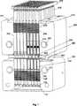
図1は、並列反応装置システム10の一定容積の実施例を示す。システム10は、反応装置ブロック100と、反応装置ブロック100内の反応器102の間での流体の流通を許容する移送ライン302を保持するプレート300をその間に挟むヘッダブロック200と、このヘッダブロック200内のヘッダバレル202とを備える。プレート300、反応器シール部320及びヘッダシール部340に対応する2のシール部が存在する。システム10は、追加的に、移送ライン302を介して、反応物を反応器102に供給するヘッダバレル202の上部を形成するプランジャー402を圧下するためのプランジャープレート400を備える。システムは、さらに、プランジャー(即ち、プランジャープレート)を駆動するための駆動システム(図1では図示しない)を備える。
【0024】
並列の準連続/セミバッチ反応を実行するために、反応物、触媒、開始剤、溶媒、除却剤等が、いくらかのヘッドスペースを残して、反応器102にロードされる。反応中に、反応器102に加えられる反応物は、プランジャー402と反対の端部で、ヘッダバレル202にロードされる。容器102は、反応装置ブロック100のウェル(well)104内に配置される。移送ライン302とシール部320及び340を備えるプレート300は、ヘッダブロックに確保され、1の移送ライン302が1のヘッダバレル202と連通し、ヘッダバレルそれぞれは、移送ラインを除いて外部から密閉(シール)されている。単一の移送ライン302が単一の反応器102と連通し、それぞれの反応器102が移送ラインを除いて外部からシールされるように、当該プレートは、また、反応装置ブロック100にシールされる。反応は、全ての成分が添加されたときに開始しても良いが、好ましくは、反応開始は、例えば、反応装置ブロック(後述する)内の温度制御システム900により、反応器に熱を供給することにより制御される。駆動システムは、プランジャーを押し下げ、それにより、反応物をヘッダバレルから反応器に供給する。これが、反応器内の内容物を圧縮する。反応器中の十分なヘッドスペースは、システム内の圧力上昇に伴って圧縮される気体が、シール手段により耐えられることを許容する。それぞれの反応器に混合ボールを添加し、この混合ボールが反応装置の内容物を転回することを許容する揺動プラットフォーム上に全体システム10を配置することにより、反応成分は、混合され得る。
【0025】
液体反応物をヘッダバレルから反応器に移送するための移送手段(ここで述べる、例えば、ポンプ、プランジャー等)は、反応器に供給される反応物の望ましい供給速度を満たすように制御される。ある実施例においては、駆動システムがプランジャーを下方に駆動して、単位時間当たりの望ましい容積で供給するように、モータが制御される。他の実施例においては、実質的に、反応物をヘッダから反応装置に完全に供給するために必要な時間が、典型的な工業プロセスの時間枠上にあるように、反応物が反応装置に供給される。この時間は、約0.5時間から約24時間の範囲であり、好ましくは、1〜12時間の範囲である。全体として、化学動力学(化学反応速度論)が、速いフィード速度を許容する速い化学反応及びその反対のものにしたがって、望ましいフィード速度を選択するために使用される。このため、フィード時間は、約1分から約48時間の範囲であっても良い。
【0026】
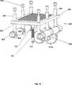
他の実施例が図2に示され、ここでは、反応装置システム10は、複数の反応装置ウェル104を有する反応装置ブロック100を備える。移送ライン302は、ポンプ20とそれぞれのウェル104との間の流体の流通を許容する。ポンプ20は、ヘッダバレル202から反応物を取得するためのフィードライン22を有する。この実施例では、反応器は、独立してシール可能であり(例えば、スクリュキャップ及び他のシール手段)、定容反応を許容する。チェックバルブ(逆止弁)は、移送ライン中への背面拡散を避けるために追加可能である。この実施例では、反応物を反応器に供給する方法は、1のポンプである。1以上の、例えば、2、3それ以上のポンプ、反応器の数までのポンプが存在しても良い、あるいは、いくつかの実施例では、反応器の数以上のポンプが存在し得る。好適なポンプは、シリンジポンプ及びギヤポンプを含む。その代わりに、プレート(図示しない)が、それぞれの反応器をシールすると同時に、移送ライン302をそれぞれの反応器に接続することができる。後述するプレート300は、この目的のために使用可能である。他の代替手段は、移送ライン302中にバルブを提供すること、反応器からヘッダに至る逆の流れを防止すること、あるいは、単一の流量計あるいはポンプを使用して、迅速で逐次的に、ヘッダバレルからの流れを、それぞれの反応器に向けることである。
【0027】
好ましい反応装置ブロック100は、図3に詳細な切断図として示される。反応装置ブロック100は、反応物、触媒、開始剤、溶媒等を受け入れるための着脱可能な容器102を含む。反応装置ブロック100中に形成されたウェル104は、容器102を含む。ある実施例では、ウェル104は、反応装置ブロック中に配置され、反応器としての機能を果たす。好ましい実施例では、着脱可能な容器102は、いくつかの利点があるので、ウェルの内側で使用される。例えば、反応と予備試験(例えば、スクリーニング)とに続いて、さらなる詳細な特性評価のために、反応装置ブロック106から、容器102のサブセットを除去することができる。着脱可能な容器102を使用するときには、さらに、所定の組合せの反応物、生成物及び反応条件に対して適当な材料から構成される容器102を選択することができる。重要な投資となる反応装置ブロック106とは異なり、容器102は、使用後に損傷している場合には廃棄可能である。最後に、システム10のコストを低減し、市販の利用可能な容器に対応するように反応装置ブロック100を設計することにより、標準化されたサンプル調製装置及び試験装置との互換性を確実にすることができる。着脱可能な反応器104は、プラスチック、ガラス等を含む、行われる反応に不活性である適当な材料から構成され得る。種々の寸法と形状のガラス容器が、市販で利用可能であり、種々のシール方法に対して修正可能であるので、好ましくは、反応器はガラスである。容器104は円筒形状に示されるが、正方形あるいは矩形形状を含む、いかなる便利な形状であっても使用可能である。
【0028】
図3に示すように、着脱可能な容器102のそれぞれは、好ましくは、ウェル104の底部に接触する。好ましい実施例においては、ウェル104の底部は、バネ108により囲まれ、ナット112で反応装置ブロック100の底部110にボルト締めされているバネ製プリテンショナー106の上部である。この反応器バネ105部品の詳細は、図4に示される。バネ108は、所望の圧縮量により予備負荷されている。この部品が実行する2つの関連する機能があり、(1)複数の反応器を一定にシールすることを許容すること、及び(2)反応器の高さの変化を求めることである。図3に示すように、反応器102の底部は、バネ製プリテンショナー106の上部と接触する。反応器102の上部は、後述するプレート300に対応する反応器シール部320と接触する。プレート300は、反応装置ブロック100に確保されてされているので、バネ106は反応装置を反応器シール部320にシールするための力を提供する。バネの圧縮量とバネの剛性とは、反応器上部を反応器シール部に押し込む力の量を決定する。図5は、特定の予備負荷時の特定のバネが、限られた変位に対して、ほとんどシール力を変化させず、反応器の高さの変化を求め、異なる熱膨張を算出する好ましい方法を示すグラフである。このため、異なるバネ張力は、異なる圧力を許容する。反応器内の圧力は、それ故、特定の反応に対して調整され得る。反応圧力は、大気圧から約1000 psiまで変化し得る。例えば、加熱された出発材料あるいは反応物をロードし、システムをシールし、次いで冷却することにより、あるいは、例えば、ヘッダから反応物を追加することなく(後述する連続(フィード)の実施例で)、反応装置から内容物を除去することにより、システム内で負圧を有することは可能である。
【0029】
また、反応装置バネ部品105は、それぞれの反応器中の圧力を一定に維持した状態で、反応器内の高さの変化を許容する。市販で利用可能な置換(交換用)反応器は、ある高さのバリエーションを有するので、このシステムは、高さの変化を考慮する。好ましい実施例は、それぞれのウェルに対して1のバネを使用するが、他の実施例では、1のバネが複数の反応装置ウェルと容器とに対して使用可能である。あり得る不利な点は、シールが十分ではない可能性があることであるが、ウェルの数、検討される反応(例えば、低圧反応)と同様に容器の均一性が、反応器を十分シール(密閉)するための1のバネシステムを許容し得る。
【0030】
反応装置ブロックは、所望の数のウェルを含む。図1に示される実施例は、96のウェルを有する。この実施例は、図6により明確に示され、ここでは、反応装置ブロック100の上部が複数のウェルを有する図6Aに示されている。バネ製のプリテンショナー106(詳細は図4参照)を受け入れるための複数の孔114を有する反応器の底部110を示す図6Bに、反応装置ブロック100の底部が示される。他の実施例は、上記の反応器バネシステムなしに、3つの反応器102が示される図7に示される。図7における実施例では、シールと反応器の高さの変動とは、プレート300を反応装置ブロック100に、ボルト、クリップ、クランプあるいは、当業者に既知の固定機構を用いて固着することにより配慮される。反応装置ブロックの全体寸法と反応器の容積とは、ウェルの数に影響を及ぼす。このため、大容積の反応が好ましい場合には、典型的には、少ない数のウェルが反応装置ブロックに存在する。好ましくは、少なくとも6のウェルが存在し、より好ましくは、少なくとも15のウェルが存在し、さらに好ましくは、少なくとも48のウェルが存在する。最も好ましい実施例では、少なくとも96のウェルが存在する。一般的に、ウェルの数は、好ましくは96*Nであり、ここで、Nは、約1から約100の範囲の整数であり、好ましくは約1〜約10の範囲の整数である。96のウェルを有する反応装置ブロック(あるいは96*Nのウェルを有する反応装置ブロック)は、標準的な微小滴定プレートフォーマット(あるいはこの拡張版)、特に9mm間隔の8×12のウェル配列に対応するようにしても良く、その高スループット能力と装置の標準化とにより、これが望まれる。反応装置ブロック中の反応器ウェルあるいは反応器の空間密度は、微小滴定プレートフォーマットに対して、1cm2当たり約1.25の反応器である。一般には、反応装置ブロック中の反応器ウェルあるいは反応器の空間密度は、好ましくは、1cm2当たり少なくとも約1の反応器であり、1cm2当たり約1から約10の反応器まで変化することが可能であり、半導体産業では既知のマイクロマシーニング技術及び微細電気機械的技術が使用される場合には、さらに大きくすることが可能である。反応装置ブロックは、また、後述する温度制御システムを含む。
【0031】
さてヘッダブロック200に着目すると、図3は、好ましいヘッダブロックの底部を切断した詳細図を示す。ヘッダブロック200は、反応中に、反応装置に供給される反応物を受け入れるための着脱可能なバレル202を含む。図1に示すように、ヘッダブロック200に形成されたヘッダウェル204は、バレル202を保持する。ヘッダウェル204は、バレルとして機能するが、着脱可能なバレル202は、いくつかの利点を提供する。例えば、ヘッダブロックの汚れや汚染を防止し、反応後の掃除をほとんど必要としない。着脱可能なバレル202を使用する際には、所定の反応物と反応条件とに対して適当な材料から構成されるバレル202を選択することができる。バレル202とプランジャー402との間のシールを改善する非常に高い寸法精度で、このバレルを得ることが可能である。必要であれば、バレル202は、使用後に廃棄可能である。このことは、システムのコストを低減し、市販の利用可能な容器/バレルに対応するようにヘッダブロック200を設計することにより、標準化されたサンプル調製装置及び試験装置との互換性を確実にすることができる。好ましい実施例では、ヘッダブロックは、一致した構成においては、反応装置ブロックと同数のウェルを含む。バレル202は、ガラス、プラスチック等を含む、反応、溶媒、反応物等に不活性な材料から構成され得る。反応器が好ましくはガラス製であるのと同様な理由で、好ましくは、バレルはガラス製である。
【0032】
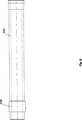
着脱可能なバレル202は、図8に詳細に示される。バレル202は、バレルの外側で、かつバレルの一端部の近傍にカラー(collar)206を含む。このカラーは、バネを圧縮した状態に維持し、反応装置ブロック中のバネ製プリテンショナーとナットと同様な機能を果たす。カラーに対向するバレルの端部は、図1に示す、ヘッダバネ210の直径に合致するように拡大されている。図1に示すように、ヘッダバネ部品208は、バレル202をヘッダシール部340に押し込むバネ210を有する。ヘッダバレルは、ヘッダバネ210の直径に合致するような寸法である。反応器バネ108と同様に、また同様な理由で、ヘッダバネは、圧縮により予備負荷されている。この場合、バネに予備負荷される圧縮力は、ヘッダバレルとバネとの適当な寸法の長さと、適当な予備負荷される力(が発生する)までバネを圧縮するヘッダブロック上部プレート212とに由来する。図1に示すように、ヘッダブロック上部プレート212は、ヘッダブロック上部の幅広部に固定されても良いし、ヘッダブロックの上部であっても良い(図示せず)。ヘッダバネ部品が果たす2つの関連した機能があり、(1)複数のヘッダバレルの一定のシール(密閉)を許容すること、及び(2)ヘッダバレルの高さの変化と異なる熱膨張とを求めることである。図1に示すように、ヘッダバレル202の上部は、ヘッダバネ210の底部と接触する。ヘッダバレル202の底部は、詳細は後述する、プレート300に対応するヘッダシール部340に接する。プレート300は、ヘッダブロック200に確保されているので、ヘッダバネ210は、バレルをヘッダシール部340に対してシールするための力を提供する。バネの圧縮量とバネの剛性とは、ヘッダバレルの底部をヘッダシール部に押し込む力を決定する。このため、異なるバネ張力は、異なる圧力を許容する。ヘッダバレル中の圧力は、それ故、特定の反応に対して調整され得る。
【0033】
また、ヘッダバネ部品208は、それぞれのバレル中の圧力を一定に維持した状態で、ヘッダバレル内の高さの変化を許容する。市販で利用可能な置換(交換用)ヘッダバレルは、ある高さのバリエーションを有するので、このシステムは、高さの変化を考慮する。好ましい実施例は、それぞれのヘッダウェルに対して1のヘッダバネを使用するが、他の実施例では、1のバネが複数のヘッダウェルとバレルとに対して使用可能である。あり得る不利な点は、シールが十分ではない可能性があることであるが、ウェルの数、検討される反応(例えば、低圧反応)と同様にバレルの均一性が、バレルを十分シール(密閉)するための1のバネシステムを許容し得る。
【0034】
プランジャー402は、ヘッダバネ部品208の中央部を挿通し、ヘッダから反応装置に反応物を供給する。ここで、プランジャーは移送手段である。プランジャー402の上部は、プランジャーを前方に駆動して、反応物をヘッダから反応装置に射出するための駆動システムに対応するプランジャープレート400に装着される。プランジャーの詳細は、図9に示される。プランジャー404の上部は、プランジャープレートに装着されるヘッド部を備える。この装着は、当業者に既知の方法により実行され得る。プランジャー上部404をプランジャープレート400に装着する好ましい方法は、プランジャー上部をプランジャープレートに螺合するように、分離可能な方法である。クランプ、ボルト締めあるいは他の方法もまた、使用可能である。交換あるいは清掃するためにプランジャーをプランジャープレートから除去することを許容するので、分離可能な装着が好ましい。プランジャーの他の好ましい特徴は、プランジャーロッド408とプランジャー上部404との間のスイベルジョイント(回動継ぎ手)406である。スイベルジョイントは、プランジャープレート400が駆動システムにより圧下される一方で、プランジャーとプランジャープレートとを結合するときの一定の自由度を許容する。プランジャーは、金属のように、適正に硬い材料から構成される得る。
【0035】
プランジャー402の下部は、詳細が図9に示され、全体が図1に示されるプランジャーチップ410を有する。プランジャーチップ410は、反応物に接触し、プランジャーが前進するにつれて、当該反応物をヘッダから反応装置内に押し込む。プランジャーチップは、プランジャーが後退するとき、ロッドから離れないように、十分な接着で、プランジャーロッド408の端部に固定される。当業者は、チップをプランジャーロッドの端部に装着するための方法を決定することができる。例えば、このチップは、プランジャーロッドの端部で熱収縮されるプラスチックから構成されても良いし、あるいは、バレル202内に圧下されるときに、ロッドシャフトとプランジャーチップとの間のO−リングをシールするようにしても良い。プランジャーチップ410は、ヘッダバレルの内容物をシールするために1つの大きい突起部411及び1以上の小さな突起部412(図9に示す)を有する。プランジャーが前方に駆動されるにつれて、突起部411、412は、シール部を形成するヘッダバレル202の内側に接触する。突起部の寸法と数とは、システム内の圧力に依存するが、好ましくは、プランジャーチップ上に2〜10の小さい突起部が存在する。プランジャーチップ410は、プラスチック等を含む、反応、溶媒、反応物等に不活性である材料から構成される。好ましくは、このチップは、PTFE(Polytetrafluoroethylene)のようなプラスチックから構成される。
【0036】
再度図1を参照して、プレート300は、反応装置ブロック100とヘッダブロック200との間に存する。プレート300は、両者のブロックに確保され、移送ライン302、反応器シール部320及びヘッダシール部340とを有する。このプレートは、さらに、熱伝導体あるいは断熱材として機能する。後述するように、熱は、この反応装置システムにおいて実行可能な反応において、重要な役割を果たす。ある環境中においては、反応装置に印加される熱は、ヘッダ中に存在する反応物に伝導する。他の場合には、反応装置に印加される熱は、ヘッダバレルに伝導しない。このため、プレートは、熱を伝導するかあるいは伝導しないように設計され得る。多くの反応に対しては、熱は反応装置にのみ印加され、ヘッダバレル中で反応装置に射出されるのを待っている反応物には印加されない。このため、典型的には、プレートは断熱特性を有し、ステンレス鋼、セラミックあるいはプラスチックのように熱伝導性の低い材料から構成される。
【0037】
プレート300は、それぞれの反応装置ブロック100とヘッダブロック200とに、これらを、反応容器中に発生する圧力に耐える十分な力で、このプレートにシールする装着方法により、装着される。装着方法は、ボルト締め、クランプ、クリップあるいは他の着脱可能なファスナーによるものであり得る。例えば、図7に示す実施例において、プレート300は、反応装置ブロック100とヘッダブロック200との間にボルト締めされる。
【0038】
プレート300を反応装置ブロックとヘッダブロックとに装着するための好ましい方法は、図10に示すラッチ機構600によるものである。ラッチ機構600は、組合せ研究に関して、いくつかの利点を提供する。このラッチ機構600は、単一の入力動作を2の対向する回動ドラム604に伝達し、このドラムは、反応器102上に垂直に移送ライン302を保持するプレートとヘッダバレル202のリップとを、容器あるいはバレルを傾けることなく引っ張り反応器あるいはヘッダバレルからの横溢が殆どあるいは全くないことを確実にし、かつ均一なシール力の印加を確実にする。それぞれの反応器とバレルとのシールは、ラッチ機構600により同時に行われる。
【0039】
図10に示すように、ラッチ機構600は、1以上、好ましくは、プレート300に固着される複数のラッチピン602を有する。このラッチピン602は、回転してラッチピン602を下方に引っ張り、その結果プレートを反応装置ブロックとヘッダブロックとに確保するラッチドラム604に嵌合する。多くの瞬間において、プレートは、ブロックにロックされる。ある実施例では、ラッチ機構600は、反応装置ブロック中の反応装置バネ部品105と、ラッチピン602の端部に半球状のボールチップ603を有するラッチピン602とにより支持される容器の配列をシールするために取り付けられる。図12に詳細を示すように、ラッチドラム604は、ボールチップ603に対応する外周に切り込まれた半球状のソケット605を有する。ソケットとピンとの形状は、重要ではない。レリーフ部607は、ラッチドラム604中に提供され、ドラムが開放位置にあるとき、ボールチップ603は、反応装置ブロック前のラッチドラム604に挿入され得る。ラッチドラム604は、次いで、その閉鎖位置(概ね、1/4回転)まで回転され、ソケット605は、ボールチップ603に当接し、ラッチピン602を下方に引っ張る。
【0040】
ラッチドラム604のそれぞれの端部606は、外側に延伸し、図11に示すように、反応器あるいはヘッダバレルを超えて、ラッチアーム608に至る。ラッチドラムアーム608は、偏心リンク610に回動可能に装着され、このリンクが、今度は、入力シャフト614とピニオン616とにより回転されるラッチギヤ612に装着される。入力シャフトは、手動あるいは自動的に回転される。入力シャフト614が回転すると、ピニオン616が第1のラッチギヤ612aに嵌合し、これが、第2のラッチギヤ612bに嵌合するので、同時に偏心リンク610を移動させる。偏心リンク610がラッチアーム608を回転し、これがラッチドラム604を回転し、ラッチピン602を固定し、反応装置ブロック100に対してプレート300を固定する。
【0041】
好ましくは、ブロックの対向する側面のそれぞれの反応装置ブロックとヘッダブロックとの中に、好ましくは、少なくとも2のラッチドラム604が存在する。ラッチギヤ612a、612bは、2の対称なラッチドラム604が、完全に対向して回転し、容器とバレルの両者をシールすることを許容する。図10及び図11に示すように、ラッチ機構は、ギヤ612a、612b、ドラムアーム608及び反応装置ブロックを備える4バー機構を完成する。この4バー機構は、迅速に作動するように最適化され、機構が閉鎖位置まで駆動されるときの機械的な利点を迅速に増大させ、それに対応して、入力ギヤ回転(量)に対するドラムの回転(量)を減少させる。駆動ギヤに対する一定の速度入力に対して、この迅速動作がドラム604を開放あるいは閉鎖し、図10に最良に示されるように、予備負荷されたバネ108が嵌合すると、ストロークの最後の部分がゆっくりとなる。一旦ラッチドラム604が、反応器シール部を容器102に対して適度に押圧するために十分な程度まで、ラッチピン602を引っ張って離すと、偏心リンク610は、数度中心軸からずれる。このことは、機構を閉鎖するために、いかなる入力する力を必要としない揺動位置を提供する。開放するためには、入力シャフト614を、この中心軸からずれた位置を過ぎる逆方向に単純に回転させ、バネ108が機構を押し開ける。
【0042】
ラッチ機構600は、反応装置ブロックのために示されるが、同様な機構が、プレート300をヘッダブロック200に装着するために、ヘッダブロック200中にある。ラッチ機構600は、反応装置ブロック中と同様な方式で、ヘッダブロック中でも作動する。このラッチ機構の他の実施例は、偏心ギヤ、ウォームギヤあるいは他の簡単な機構により、達成され得る。
【0043】
本発明の定容積の実施例においては、反応器は、移送ラインを除いて、外部からシールされ、ヘッダバレルもまた、移送ラインを除いて、外部からシールされる。これらは、選択される材料と方法とに依存して、1000psiまでの圧力に耐える、耐圧シールである。この閉鎖システムの好ましい実施例は、3つのシール部を有するが、他の実施例では、これ以上のシール部を有することもある。例えば、図2に示すシステムは、4箇所のシール部と2箇所のシール部とを有し、ここで、フィードラインは、バレル202をポンプ20と接続し、さらに2箇所のシール部を有し、ここでは、移送ライン302がポンプをウェル104に接続する。好ましい実施例では、この3のシール部は、ヘッダバレル202の内部にシールされるプランジャーチップ410と、プレート300にシールされるヘッダバレル202リップと、プレート300にシールされる反応器102リップとに存在する。これらのシール部の第1のものは上述した。
【0044】
この好ましい実施例において、ヘッダシール部340は、ヘッダバレル202のリップとプレート300との間のシール部である。同様に、反応器シール部320は、反応器102のリップとプレート300との間のシール部である。基本的に、好ましいシール方法は、リップを受け入れる部材に押し込まれる反応器のリップあるいはヘッダバレルを有する。このシール方法は、いくつかの実施例を有する。
【0045】
最も好ましいシール方法は、図3に示される。まず反応器シール部320をみると、移送ライン302の1の端部に固定するガスケット322があり、このガスケット322は、移送ライン302の外径に当接して固定され、反応器102の外径を超えて延伸する。ガスケット322は、ガスケットとプレートとの間の実質的な漏れを許容することなく、ガスケットがプレートに装着されるプレート300と対応する。ある程度の漏れが発生する可能性はあるが、反応装置ブロック100をプレート300に装着する装着手段を締め付けることにより最小限に維持される。反応器102リップがガスケット322に対して締め付けられるときは、移送ライン302の端部が、容器内に延伸する一方で、ガスケット322は、容器102のリップに一致する。ガスケット322は、反応装置ブロックを構成するウェル及び容器の配列中のそれぞれの反応器102に対して、それぞれの移送ラインを固定する、好ましくは連続シートである。連続シートは、反応器102の外径がガスケット322の端部を超えて延伸しないように確実にする利点を有し、全ての容器に対して、同時に交換可能である。ガスケットの特性は、異なるシール圧力を考慮して選択可能であり、このシールは、漏れなしで、約1000psiまでの反応器中の圧力に耐える。さらに、ガスケット材料は、反応条件と反応中に存在する化学物質とに不活性でなければならない。この実施例では、ガスケットは、Kalrezあるいは他の耐化学薬品性のあるエラストマーのような、パーフルオロエラストマーから構成可能である。最も好ましいガスケットは、シリコンゴム封止PTFE(テフロン(登録商標))から作成される。
【0046】
同様に図3に示すように、ヘッダシール部340の最も好ましい実施例では、移送ライン302の他の端部に固定するヘッダガスケット342が存在し、このヘッダガスケット342は、移送ライン302の外径に当接して固定され、ヘッダバレル202の外径を超えて延伸する。ヘッダバレル202のリップが、ヘッダガスケット342に対して締め付けられるときは、移送ライン302の端部が、ヘッダバレル内に延伸する一方で、ガスケット342は、バレル202のリップを受け入れることを提供する。ヘッダガスケット342は、ヘッダブロックを構成するウェル及びバレルの配列中のそれぞれのヘッダバレル202に対して、それぞれの移送ラインを固定する、好ましくは連続シートである。連続シートは、ヘッダバレル202の外径がヘッダガスケット342の端部を超えて延伸しないように確実にする利点を有する。ガスケットの特性は、異なるシール圧力を考慮して選択可能であり、このシールは、漏れなしで、約1000psiまでのヘッダバレル中の圧力に耐える。さらに、ガスケット材料は、反応条件と反応中に存在する化学物質(例えば、反応物)とに不活性でなければならない。この実施例では、ガスケットは、Kalrezあるいは他の耐化学薬品性のあるエラストマーのような、パーフルオロエラストマーから構成可能である。最も好ましいガスケットは、シリコンゴム封止PTFE(テフロン(登録商標))から作成される。
【0047】
他のシール(密閉)の実施例は、図13に示される。図13A及び図13Bに示すように、反応器シール部320は、プレート300に切り込まれたチャネル304に嵌合するゴム製の反応器ガスケットバネ322を有する。チャネル304の特徴は、反応器102のリップを受け入れるためのテーパ部306である。反応条件と検討する反応中の化学物資とに関する付加的な不活特性を提供するために、追加的に、第2の不活性ガスケット324が、反応器ガスケットバネ322と反応器102との間にある。図13では示されていないが、これと同様なシールがヘッダシール部に関しても使用可能である。当該シールが、漏れなしに約1000psiまでの反応装置内の圧力に耐えるように、ガスケット及び第2のガスケットの特性は、異なるシール圧力を考慮して選択され得る。さらに、ガスケット材料は、反応条件と反応中の化学物質(例えば、反応物)とに対して不活性でなければならない。この実施例では、ガスケットはシリコンゴムから構成され得る。最も好ましくは、ガスケットは、Kalrezあるいは耐化学薬品性エラストマーから構成される。第2のガスケットは、PTFE(テフロン(登録商標))から構成され得る。
【0048】
さらに、他のシールの実施例が図14に示される。O−リング326が、反応器102の端部に配置されるスプール328の内部に載置される。移送ライン302は、このスプールの中央から、反応物をフィードする。反応器102のリップが、反応器シール部320に対して固定されたときに、シールが形成される。図7に示すように、スプール328は、これに対応するように設計されているプレート300に切り込まれたチャネル304の内部に載置される。スプールは、好ましくは、プラスチック、より好ましくは、PTFE(テフロン(登録商標))から構成される。O−リングは、シリコンゴムのような標準的材料から構成される。このシールは、特に良好な断熱特性を有する。図14は、また、バレル202中の混合ボール370を示す。
【0049】
さらに、他のシール実施例が図15に示される。この実施例では、反応器シール部320は、反応器102のリップを受け入れるためのプレート300に切り込まれたチャネル304を備える。この実施例において、プレート300は、それぞれの容器に対する1つの独立した部材であり、好ましくは、反応器を損傷しないようなプラスチック材料である。シールするために、反応器の内面は、突起部308により、チャネル304のテーパ部306に係合する。図15に示すヘッダシール部340に関して、プレート300のヘッダ側にあるチャネル304のテーパ部306に装着するテーパ状リップ310まで、ヘッダバレル202のカラー206が延伸する。このシステムは、さらに、ヘッダバレルをプレートに係合してシールを形成する。好ましくは、このシール実施例の濡れる部位は、反応条件と反応中の化学物質とに不活性である。また、図15は、反応器102及びヘッダバレル202内の混合ボール370を示す。
【0050】
移送ラインは、ヘッダから反応装置へ反応物を移送する機能を果たす。それらは、好ましくは、検討する反応物に対して不活性である。さらに好ましくは、バレルから反応装置への射出速度が、反応装置からバレルへの背面拡散速度よりも大きくなるように、移送ラインの寸法(長さあるいは直径)が規定される。好ましくは、複数の移送ラインが、反応装置からヘッダへの反応成分の背面拡散量を実質的に制限するような寸法である。例えば、移送ラインに対して、十分小さい直径が選択された場合には、反応するあるいは反応中で必要とされる化学物質(溶媒や清浄剤等)は、反応装置内に残存し、ヘッダには拡散しない。移送ライン302は、図2に示すように、管状あるいは溝状であり得る。移送ラインの寸法は、狭義には重要ではなく、キャピラリのように、微視的寸法の溝と巨視的寸法の溝との両者を含むことができる。移送ライン302は、図13、図14及び図15に示すように、プレート300内のチャネルであり得る。図1に示す好ましい実施例では、移送ライン302は、プレート300の孔に嵌合する、不活性な挿入部である。好ましい移送ライン302の詳細が図16に示され、ここでは、移送ラインは、ヘッダから反応装置への流体の流通を許容する、挿入部の長手方向に走るライン312を有する。挿入部の一端には、挿入部をその位置で保持し、動かないようにするフランジ314が存在する。このフランジは、好ましくは、プレート300の反応装置側(図1に詳細に示す)に配置される。図3に続いて、ライン312は、反応装置側よりもヘッダ側で大きい直径であるように示され、それが反応装置からヘッダへの化学物質の拡散を制約することが望まれている。挿入部の他の特徴は、移送ライン312の軸と直交するチャネル316(図16に示す)であり、挿入部のそれぞれの端部で、混合ボールがライン312を閉鎖できないように、混合ボールの存在下での反応物の流れを許容する。
【0051】
好ましい駆動システムが、図17及び図18に示される。まず図17を参照して、プレート300に対してシールされる複数の反応器102を有するように反応装置ブロック100が示され、このプレート300が今度は、反応装置ブロック200をシールする。複数のプランジャー402が、プランジャープレート400からヘッダブロック200まで延伸するように示される。反応装置ブロック100底部からプランジャープレート400上部に至る全体のシステムは、駆動システム500と対応し、この駆動システム500は、プランジャープレートを押し下げ、プランジャーがヘッダバレルから反応器に反応物をフィードするような機能を果たす。概念的には、駆動システム500は、簡単には、その重力によって、プランジャープレートを下方に駆動する十分な重量を有する錘りであり得る。しかし、そのようなシステムは、全体システムは混合用の揺動プレート上に配置される他の具体例では機能し得ない。
【0052】
このため、好ましい駆動システムは、1の端部でそこから右方向に延伸する着脱可能なキャリッジ506と、他の端部でそこから右方向に延伸する固定アーム508とを具備するセンタサポート504を有するフレーム502を備える。センタサポート504は、プレートとして示されるが、2以上のレールの組みを含む、これ以外の設計(デザイン)が当業者に対して明らかになるであろう。キャリッジ506は、1以上のレール510の長手方向に沿って自由に移動し、このレール510は、円滑な動作を許容するために、センタサポート504に固着され、クランプやベアリング(図示しない)によりキャリッジに装着され得る。その代わりに、クランプ及びベアリングをセンタサポートに固着して、レールがキャリッジの背面に装着されても良い。センタサポート504に関して、キャリッジ506の動作時の摩擦を低減することが望ましい。装着方法は、本発明に関して重要ではなく、当業者が、他の摩擦を低減した装着方法を使用することは可能である。
【0053】
キャリッジ506は、その底部がプランジャープレート400に接触する状態で、レール510から略垂直に延伸する平板部512を備える。キャリッジ506は、この平板部のみを備えるが、反応システム内(例えば、反応器、ヘッダバレル及び移送ライン)の高い圧力に対しては、キャリッジが高い力(圧力)に耐えることが可能であることが好ましく、図17に示す実施例が、そのようなキャリッジを例示する。図17のキャリッジ506は、キャリッジ支持板514に、その両端部で接続される平板部512を備える。キャリッジ平板部512とキャリッジ支持板514とは、キャリッジ背板516に装着され、このキャリッジ背板516が今度は、レール510に沿った動作のためのクランプとベアリングとに結合される。この好ましいキャリッジ506の設計は、変形なしに、96のプランジャーを前進させることを可能にする。このキャリッジ設計は、本発明に関しては重要ではなく、他のキャリッジ設計が当業者に明らかになるであろう。
【0054】
好ましい駆動システム500の背面が図18に示される。キャリッジ506の背面は、センタサポート504を貫通して延伸し、案内スクリュ518に装着される。案内スクリュ518は、支持体520によりセンタサポート504に装着され、案内スクリュ518は、支持体520内で回動可能である。案内スクリュ518は、キャリッジ506背面上の対応するネジ部に螺合され、案内スクリュ518が回動したときに、キャリッジ506がレール510に沿って上下する。歯型ベルト522は、案内スクリュ518の一端をギヤヘッド524に結合する。ベルト522は、歯型にされる必要はないが、そのようなベルトでスリップを避けることが望ましい。案内スクリュの回動方法は、本発明に対して重要ではなく、他の動作伝達方法が当業者に明らかになるであろう。モータ526がギヤヘッド524を回転する。モータ526は、ACあるいはDC駆動であり、好ましくは、Industrial Device社製のG23PI−S23−0100あるいはこれと等価物のような、市販で利用可能なギヤモータである。図18に示す好ましい駆動システムの他の特徴は、さらなるスリップを避けるベルト522上の張力を維持するためのベルトテンショナー532を含む。さらに、図18に示すように、Applied Motor Products社製の型式PD2035あるいはこの等価物のような、コマンドをモータに対する電気信号に変換するためのモータ増幅器528が存在する。
【0055】
この好ましい駆動システム500は、キャリッジの動作に先立って、案内スクリュ518を回動させ、ベルト522を駆動するギヤヘッド524及びギヤ530を起動するモータ526により作動する。それが強力でコンパクトであり、垂直に、あるいは水平にあるいは他の角度で、作動可能であるので、このシステムが好ましい。これらの特徴が与えられた場合、反応装置を伴う駆動システムは、混合ボールを使用して反応及び反応物を混合するための揺動プラットフォームあるいは振動機構上に配置され得る。安定した垂直位置では、明らかに混合ボールは効果的ではなく、磁石撹拌棒のような他の混合方法が使用される。反応生成物は、混合強度に影響され得るので、均一な混合速度は、いかなる生成物の差異も混合のばらつきには起因しないことを確実にする。このため、混合ボールが本発明に関しては好ましい。本発明においても有益な他の混合実施例に関して、ここで参照により引用される、米国出願09/177170号(1998年10月22日受理、代理人整理番号65304−044)を参照する。
【0056】
出発材料の性質、反応タイプ及び反応生成物特性と反応速度とを評価する方法によって、図19に示すように、全体システムあるいは反応装置ブロック100をチャンバ700内に収容することが望ましい場合がある。チャンバ700は、脱気され、あるいは、窒素またはアルゴン等の不活性ガスのような好適なガスで充填されても良い。このチャンバは、最も有益には、Vacuum Atmospheres,Inc.により市販されるようなグローブボックス(あるいは乾燥ボックス)である。ある場合には、サンプル調製中の汚染を最小限に抑えるため、例えば、酸素感応性触媒の被毒を抑制するために、チャンバ700は、出発材料を容器102及び/又はバレル202にロードする間のみ使用するようにしても良い。他の場合には、チャンバ700は、反応プロセス中あるいは特性評価時に使用され、全ての容器102から同時に1以上の流体を除去する都合の良い方法を提供するようにしても良い。このようにすれば、気体反応物は、全ての容器102に同時に添加され得る。
【0057】
注目すべき図19の他の特徴は、支持プラットフォーム720に回動可能に装着され、モータ(図示せず)により駆動される回転プレート710である。これは、この明細書を通じて議論される揺動プレートの代替実施例である。図19に示す実施例は、全体の反応装置システムと駆動システムとが装着された回転プレート710を示す。回転プレートは、予め定められた速度で回転し、反応器及び/又はヘッダバレル内の混合ボールがその内容物を混合することを許容する。
【0058】
典型的には、反応物は液体である(しかし、それらは、1以上の気体であっても良い)。反応の1以上の内容物(溶媒、触媒、モノマー、清浄剤、開始剤等)が液体である場合には、自動液体取扱システムがこれらの液体を取り扱うために使用可能である。図20に図解するように、ロボット化液体取扱システム800が、容器とバレルとに出発材料をロードするために使用され得る。このロボットシステム800は、測定された量の液体をそれぞれの容器及び/又はバレルに分配するプローブ801を有する。ロボットシステム800は、3軸移動システム802を使用して、プローブ801を操作する。このプローブ801は、フレキシブルチューブ804を介して、1以上の液体反応物のソース803に接続される。このフレキシブルチューブ804に沿って配置されるポンプ805は、ソース803からプローブ801に液体反応物を移送するために使用される。好適なポンプ805は、蠕動ポンプ及びシリンジポンプを含む。ポンプ805の下流に配置される多口弁806は、容器及び/又はバレル内に(液体反応物を)分配するために、ソース803からどの液体反応物をプローブ801まで送るかを選択する。図20は、ロード用の1つの反応装置ブロック100を示すが、一連の容器あるいはバレルあるいはヘッダブロックを示すこともできる。
【0059】
ロボット化液体取扱システム800は、プロセッサ807により制御される。図20に示す実施例では、ユーザは、まずソフトウェアインターフェースを使用して、プロセッサ807に実行パラメータを提供する。典型的な実行パラメータは、容器の座標軸とそれぞれの容器中の反応混合物の初期組成とを含む。この初期組成は、ソース803それぞれからの液体反応物のリストとして、あるいは特定の容器に相対的に種々の液体反応物を逐次添加することとして、特定可能である。同様に、ロボット化取扱システムは、反応物をヘッダバレルに分配するようにしても良い。液体ロボット取扱システムが成分を分配するために使用可能な実験を設計するために使用され得るコンピュータプログラムに関して、ここに参照により引用される米国出願09/174986号(1998年10月19日受理、代理人整理番号65304−013)を参照する。さらに、ロボット化ワークステーションに関して、米国特許5104621号及びWO98/40159号を参照する。
【0060】
ロボット取扱システムは、図21に示す手順に使用可能である。まず、図21Aを参照して、液体反応物は、反応器102及びヘッダバレル202(プランジャーチップ410とともに示される)の両者に添加される。図21Bは、オリフィス312を備える移送ライン302を有するプレート300が、ヘッダシール部を形成するヘッダバレル202に装着され、追加的に、プランジャー402がヘッダバレル202から気体を排出するために前進するステップである。図21Cを参照して、ヘッダバレル202は、反転され、プレートを反応器シール部を形成する反応器102に接続する。オリフィス312の寸法で与えられる表面張力のために、ヘッダ内の反応物は横溢しない。この反応装置システムは、次いで、駆動システムと一緒にされ、さらに完成品が、図21Dに示すように、回動軸32の回りに前後に揺動する揺動プラットフォーム30上に配置される。
【0061】
図22は、反応中のヘッドスペースの圧縮により低圧となる、本発明の他の実施例を示す。移送ライン302を含むプレート302にシールされる単一の反応器102がそこに示される。ヘッダバレル202もまた、プレート300にシールされる。ヘッダバレル202は、駆動システム500により制御され、前後に動くことにより、ヘッダバレル202の容積を制御するプランジャー402を有する。これは、上述したものと同様である。この実施例において、反応器102は、可変容積の反応器であり、反応器駆動システム500’により制御され、前後に動くことにより、反応器102の容積を制御するプランジャー402’を有する。制御可能で可変容積の反応器に対する反応器駆動システム500’は、詳細を説明したヘッダ駆動システム500と類似あるいは同一である。両者に関して、プランジャー402、402’の1の端部は、キャリッジ506、506’の一部あるいは別体であっても良いプランジャープレート(図示せず)に装着される。キャリッジ506、506’は、モータ526、526’により回転される案内スクリュ518、518’により前後に移動させられる。プランジャーチップ410、410’がそれぞれ、バレルあるいは容器の内側に当接することにより、プランジャー402、402’の端部で、ヘッダバレル202と反応器102とがシールされる。全体システムが、プレート300の支持体を含む支持体500上に組み立てられる。反応器プランジャー402’に関して、それぞれのプランジャーは、反応器を貫通し、反応器プランジャー410’が後退すると、反応器容積が増加するように、反応器内側とシール部を形成するチップ410’を有する。反応器プランジャーが前進すると、反応器容積が減少する。反応器プランジャーは、ヘッダプランジャーに対して上述したように、それぞれ、複数の反応器プランジャーを移動する他のプランジャープレートに装着される上部を有する。
【0062】
図22のシステムを作動するために、液体及び気体を、混合ボールあるいは他の混合部材(前述した)と一緒に、手動であるいは自動的に、容器102とバレル202とに添加する。容器とバレルとは、次いで、プレート300にシールされ、駆動システム500、500’に接続される。全体システムは、さらに、反応中の混合のために、揺動プレートあるいは回動プレート(図19に示すように)上に配置される。反応器プランジャー402’を、ヘッダプランジャー402が前進する速度と同じ速度で後退させることにより、反応器とヘッダとの容積の合計は、一定に維持され得る。この方法に代わるものでは、この実施例は、上述したように、ヘッダプランジャーのみを動作させることにより、一定の利用可能な反応器容積で、作動することを許容する。図22には、1の反応装置システムしか示されていないが、前述した一定容積の実施例に対して、上述したようないかなる数の対応する容器とヘッダとが存在しても良い。反応器及びヘッダブロックあるいは上述したモジュール中に、6、20、48あるいは96あるいはそれ以上の反応装置システムが存在し得る。
【0063】
本発明の他の実施例は、連続反応装置システムの実施例を示す図23に示される。図23に示すように、反応器102の1の側部は、移送ライン302を介して、ヘッダバレル202に接続される。反応器102は、プレート300にシールされる。この実施例の当該部分は、その詳細を上述したように作用する。
【0064】
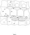
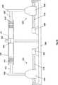
さらに、保持タンク150(あるいは貯蔵タンクと呼ぶ)は、第2のプレート154内に含まれる第2の移送ライン152を介して、反応器102の他の端部に接続される。第2の移送ラインと第2のプレートとに対する種々の実施例は、プレートと移送ラインとに対して上述したもののいずれであっても良い。ここで、反応器は、一定の利用可能な容積であり、その一方で、それぞれキャリッジ506、506’により駆動されるプランジャー402、402”を使用して、ヘッダバレル202と保持タンク150とは、その容積は可変である。番号付けした部分は、類似の番号付けした部分に対して上述したものと同様である。実行時には、ヘッダバレル202の内容物は、反応器102に押し込まれる。一旦、望ましい反応時間あるいは他の判定条件が一致すると、内容物のある部分は、反応を停止させる化学物質が充填される保持タンク内に引っ張られる。このため、反応器中の滞留時間は、反応の特定のタイプに合うように変更可能であり得る。保持タンクプランジャー402”を、ヘッダバレルプランジャー402が前進する速度と同じ速度で後退させることにより、反応器と保持タンクとヘッダとの容積の合計は、一定に維持され得る。並列システム(図示せず)に関して、複数の反応器に対応し、これにシールされる複数の第2の移送ラインは、また、複数の保持タンクに対応し、これにシールされる。第2の移送手段は、複数の保持タンクに対応して提供され、第2の移送手段は、保持タンク内の第2の移送ラインを介して、複数の反応器内の内容物の少なくとも所定量を除去するために採用される。第2の移送手段は、ポンプであっても良く、第2の移送手段は、チューブであっても良い。好ましくは、第2の移送手段は複数のプランジャー402”を備え、それぞれのプランジャーは、保持タンクを貫通し、プランジャーが後退すると、内容物が第2の移送ラインを介して、反応器から除去され、保持タンクに移送されるように、保持タンクの内側とシール部を形成するチップ410”を有する。ヘッダプランジャーと同様に、好ましくは、それぞれのプランジャーは、プランジャープレートが移動すると、同時に複数のプランジャーの全てが移動するように、第2のプランジャープレートに装着された上部を有する。第2のプランジャープレートは、第2の駆動システム500”により駆動される。
【0065】
他のこれに代わる実施例では、反応装置とヘッダブロックとは分離して、それぞれが所定の数の反応に対して一定数のウェル及び容器を有するように、モジュール化されても良い。モジュールの使用は、一体化ブロックに対していくつかの利点を提供する。例えば、ブロック寸法は、反応物の数及び組合せライブラリのサイズにより、容易に調整可能である。さらに、単一で大きなブロックよりも、比較的小さいモジュールは、取扱、輸送、組立が容易である。損傷したモジュールは、予備モジュールと迅速に交換可能であり、それにより修繕コストとダウンタイムとを最小限に抑える。最後に、モジュールの使用は、反応パラメータの制御性を改善する。例えば、異なるモジュールのプランジャープレートは、モジュール間で変更可能な容器それぞれの異なる速度、温度あるいは圧力で、前進駆動され得る。多数のヘッダ容器が、それぞれの反応器に(反応物を)フィードし、多数の保持容器が、それぞれの反応器から内容物を除去するようにしても良い。
【0066】
本発明のウェル、反応器、ヘッダバレル、貯蔵タンク等は、組合せ様式、即ち、迅速なシリアル及び/又は並列様式で、例えばライブラリあるいは配列でフォーマットで配置され、及び/又は作動され得る。組合せ配列では、反応器、ヘッダバレル、貯蔵タンク、プランジャー等の配列中の複数の材料のそれぞれは、この配列中の他のものと、ある意味で、同一あるいは異なることが可能である。このような材料の差異は、組成的(異なる組成を有するような)、あるいは定量的(材料の量的差異)である可能性があり、あるいは処理パラメータ(温度、圧力、雰囲気組成等)または、この明細書を読み返して当業者が認識する他の差異も含み得る。さらに、配列中のそれぞれの構成要素は、それぞれの反応が他の反応とは隔離された異なる反応装置中に存在する。
【0067】
配列あるいはライブラリのフォーマットは、典型的には、少なくとも6の異なる反応、例えば、反応する6の異なる成分あるいは、6の異なる反応条件(温度あるいは圧力のような)を備える。他の実施例では、少なくとも25の反応が存在し、さらに他の実施例では、少なくとも48、あるいは96、あるいは124、あるいはそれ以上の反応が存在する。組合せ配列の形成方法により、それぞれの化合物、材料あるいは成分は、純粋ではない。同様に、反応条件、プロセス、触媒あるいは溶媒は、本発明の1以上の配列を利用して、既知の方法で変更可能である。
【0068】
それぞれの容器及び/又はそれぞれのヘッダバレルの温度をモニタ(監視)し、制御する能力は、本発明の重要な観点である。化学反応中に、温度は、反応生成物の構造と特性とに大きな影響を及ぼし得る。例えば、フリーラジカルエマルジョン高分子化において、高分子構造と特性−分子量、粒子サイズ、ガラス転移−とは、反応温度による影響を受け得る。組合せライブラリのスクリーニングあるいは特性評価中に、温度制御とライブラリ構成要素のモニタとは、構成要素間で意味のある比較を行うためには、しばしば不可欠である。最後に、温度は、スクリーニング判定指標として使用可能であり、あるいは有益なプロセス及び生成物変数を計算するために使用され得る。例えば、発熱反応の触媒は、ピーク反応温度に基づいてランク付け可能であり、温度測定は、反応速度と転化速度とを計算するために使用され得る。
【0069】
温度モニタ及び制御システムの1の実施例は、それぞれの容器102と熱的に接触する温度センサを含む。好適な温度センサは、被覆した、あるいは被覆されない熱電対(Thermocouple、TC)、抵抗熱電測定デバイス(Resistance Thermometric Device、RTD)、サーミスタを含む。温度センサは、温度センサから受信する信号を標準温度スケールに変換する温度モニタと通信する。追加プロセッサーは、温度モニタから温度データを受信する。閉鎖ループ様式のヒータ制御と同様に、壁補正及び異なる容器102間の単純な比較とを含むようなデータに基づいて、このプロセッサは計算を実行する。好ましい実施例では、外部コンピュータと通信する、専用の温度コントローラが提供される。このため、制御の実行と計算とは、それぞれの場所で実行されるようにしても良い。
【0070】
用途に応じて、それぞれの容器及び/又はバレルは、実験中に、同一の温度あるいは異なる温度で維持され得る。例えば、異なる容器中で、最初に通常の出発材料と化合物とを結合させ、次いで均一な温度で混合物を反応させることにより、触媒活性に関する化合物のスクリーニングを行い得る。さらに、多数の容器中で、スクリーニングステップで使用したものと同一の出発材料と有望な触媒とを組み合わせることにより、この触媒の特性を評価することができる。次いで、触媒性能(速度、選択性)に及ぼす温度の影響を把握するために、この混合物を異なる温度で反応する。多くの例では、処理中に、容器の温度を変更する必要があり得る。例えば、転化率を最大にするために、可逆的な発熱反応が進行する混合物の温度を低下させても良い。あるいは、特性評価ステップ中に、相転移(融解範囲、ガラス転移温度)を検出するために、反応生成物の温度を上昇させても良い。最後に、熱量データを取得するために、反応中に容器内のモニタ温度を変更する一方で、反応装置ブロックを一定温度に維持しても良い。
【0071】
明確を期して、図1の一体化反応装置ブロック100を参照して、温度モニタ及び制御システムを説明するが、この開示は、前述したモジュール化反応装置ブロックに対しても同様に適用される。反応と反応物との温度は、モニタ及び制御に関して重要であるので、温度モニタは、反応装置ブロック及び/又はヘッダブロック内の都合の良い位置で実行され得る。例えば、図1あるいは図3に示す反応装置ブロック100のそれぞれの容器102は、反応装置ブロック100内のチャネル120に装着される加熱エレメント(カートリッジヒータのような)を装備する。類似のチャネル220がヘッダブロック200中に存在する。他の実施例では、それぞれの容器は、容器102とバネプリテンショナー106との間に固有の加熱エレメントを有する。さらに他の実施例では、チャネルは、加熱流体あるいは冷却流体を搬送する反応装置ブロック及び/又はヘッダブロックを貫通し得るので、ブロック全体を所望の温度まで加熱あるいは冷却する。それぞれの容器及び/又はバレルに対する独立したヒータを用いた流体を加熱あるいは冷却する実施例の使用は、完全な温度制御を提供する。このため、それぞれの反応の温度は、−100℃から約300℃の範囲であり得る。
【0072】
閉鎖ループを完成するためには、それぞれの容器及び/又はバレルの温度をモニタするために、温度モニタが含まれ、その結果、容器102あるいはバレル202の温度は独立に制御可能になる。他の実施例は、加熱エレメント及び温度センサを容器及び/又はバレル内に配置することを含み、それは結果として、より正確な温度モニタと内容物の制御とにつながり、1のパッケージ中に温度センサと加熱エレメントとを組み合わせる。組み合わされた温度センサと加熱エレメントとの例は、サーミスタであり、その抵抗は温度に依存するので、温度モニタ及び制御の両方に使用可能である。多くの異なる温度モニタ及び制御の実施例は、ここに参照により引用される、米国出願09/177170号(1998年10月22日受理、代理人整理番号65403−044)で議論されている。
【0073】
揺動プレートの揺動速度あるいは回動プレートの回動速度あるいは組成あるいは混合ボールの密度と同様に、反応容器及び/又はヘッダバレルのサイズに応じた種々のサイズの混合ボールを添加するような混合変数は、反応経路に影響を及ぼし、そのため、反応生成物の特性に影響する。例えば、ここで参照により引用する米国出願09/177170号(1998年10月22日受理)に記載されるように、撹拌棒、撹拌羽根トルク、回転速度及び形状と関連する。
【0074】
多くの異なるタイプの反応が、本発明の装置と方法とを使用して、並列に検討可能であり、カルボニル化、(接触)水素化改質、ヒドロキシカルボニル化、水素化カルボニル化、水素化エステル化、水素化、移動水素化、水素化シリル化、水素化ホウ酸化、水素化アミノ化、エポキシ化、アジリジン化、還元アミノ化、C−H活性化、挿入反応、C−H活性化−挿入反応、C−H活性化−置換反応、C−ハロゲン活性化、C−ハロゲン活性化−置換反応、C−ハロゲン活性化−挿入反応、シクロプロパン化、アルケン複分解及び、アルケンオリゴマー化、アルケン高分子化、アルキンオリゴマー化、アルキン高分子化、コポリマー化、CO−アルケン共重合オリゴマー化、CO−アルケンコポリマー化、CO−アルキン共重合オリゴマー化、CO−アルキンコポリマー化を含む全ての種類の高分子化反応を含む。研究に好ましい1つの反応は、配位高分子化、陽イオン高分子化及びフリーラジカル高分子化を含む高分子化反応である。高分子化反応は種々の方法により実行可能であるので、高分子化は、その機構及び装置で検討するために好ましい反応である。
【0075】
実行可能な工業的に重要な反応の多様性により証明されるように、準連続及び連続プロセスを使用して、1以上の反応物がプロセス反応装置内に制御された速度で計量される、本発明の装置と方法とは重要である。他のプロセスは、反応物は制御された速度でプロセス反応装置に計量され、その一方で生成物は同時に反応装置から除去される、連続方式で行われる。現実的なプロセス条件の下で、候補触媒、材料及びプロセスをスクリーニングすることは、しばしば重要である。多くの触媒反応は、反応進行中に低濃度で1以上の反応物が維持されているときに、最も好ましく進行する。準連続及び連続プロセスは、導入速度と同等以上の速さで、反応装置中で反応物が消費される場合には、そのような条件が確立されることを許容する。反応進行中に出発材料の瞬間濃度よりも、生成物の最終濃度の方が高いので、準連続及び連続プロセスは、また、工業的な反応装置能力の効率的な使用を許容する。さらに、放熱速度は、反応装置への反応物の添加速度により制約されるので、準連続及び連続プロセスは、着実に制御される。準連続及び連続プロセスは、反応速度よりもさらにゆっくりと反応物を添加することが可能で、その結果、反応物の瞬間濃度は、プロセス全般に低いが、反応装置からの生成物濃度は高い。このモードが有用な反応は、中間及び多環を形成する環化反応、1以上の反応物が望まれない自己反応あるいは高分子化を受けやすい反応及び1以上の反応物が触媒に対する禁止剤として作用する触媒プロセスを含む。さらに、準連続及び連続プロセスは、低濃度のモノマーを使用して発生可能であるので、より化学的に均一なコポリマーの生成を許容する。
【0076】
懸濁高分子化プロセスは、高分子分散液あるいはコロイド、典型的には、界面活性剤により水中で安定化された小さな高分子粒子のコロイドを生成する。このようなコロイドは、モノマーのような有機溶媒あるいは分子の存在下で、しばしば不安定である。準連続及び連続プロセスは、プロセス中でモノマー濃度が低く維持されるので、ゆっくりとモノマーを添加して、エマルジョンを生成することができる。さらに、準連続及び連続プロセスは、熱的開始剤のように、不安定で高い反応性の反応物が、反応進行中の全般に渡って計量されることを許容し、その結果、反応が完結するまで、反応物の有効な濃度が維持される。
【0077】
上記の説明は、理解を助ける意図でなされ、制約を意図したものではないことは、理解されるべきである。上記説明の査読に基づいて、多数の実施例及び応用例が、当業者に明らかになるであろう。そのため、本発明の範囲は、上記説明を参照して決定されるべきではなく、クレームにより権利が与えられる均等な範囲に沿って、添付のクレームを参照して決定されるべきである。特許出願及び刊行物を含む、全ての文献及び引例の開示は、ここで、全ての目的に対して、参照により引用される。
【0078】
【発明の効果】
本発明によれば、特定の反応のために選択された、反応物、触媒、開始剤、溶媒等の制御に加えて、温度、圧力、混合、反応物の添加速度及び/又は生成物の除去速度を含む、一定の反応条件が制御可能である。
【図面の簡単な説明】
【図1】本発明に対応する並列反応装置システムを図解する。
【図2】本発明に対応する他の実施例である並列反応装置システムを図解する。
【図3】好ましい反応装置ブロック、プレート及びヘッダブロック部品の詳細な切断面を示す。
【図4】反応装置ウェルの底部を支持する、好ましい実施例の詳細図を示す。
【図5】好ましい実施例で使用される予備負荷された線形バネに関する、力対変位曲線を示す。
【図6】好ましい実施例で、ガラス製シリンジを保持するヘッダブロックの上面と底面図とを示す。
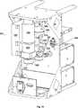
【図7】僅か6つのウェルと、ヘッダブロックに統合されたヘッダ容器と、一体のオリフィス/断熱プレートと、反応装置ウェルの底部を支持するゴム製クッションとを使用する連続フィード並列反応装置の他の実施例を図解する。
【図8】ヘッダシリンジの好ましい実施例の図面である。
【図9】シリンジプランジャーの好ましい実施例の図面である。
【図10】反応装置ブロック及び隠された1の容器以外の全ての容器とともに、好ましい反応装置ブロックのラッチ機構の図面である。
【図11】好ましい反応装置ブロックのラッチ機構の図面である。
【図12】好ましいラッチドラムの詳細図である。
【図13】断熱ブロック内の円錐形突起部で圧下することにより広げられる、不活性の「テーパ状密閉シート」を利用する反応器シール部の他の実施例を図解する。
【図14】不活性なスプールに取り付けられたO−リングから構成される複合材シールを利用する反応器シール部の他の実施例を図解する。
【図15】反応器と係合し、ヘッダ容器とテーパ状嵌合部で嵌合する、シール部として独立した断熱オリフィスの他の実施例を図解する。
【図16】保持プレートに圧下されるヘッダ容器から、反応容器を分離するために使用されるオリフィス挿入部の好ましい実施例の詳細図を示す。
【図17】反応装置ブロック及びヘッダブロックとともに、駆動システムの好ましい実施例の前面図を示す。
【図18】好ましい駆動システムの背面図を示す。
【図19】2つの反応装置と駆動システムとが回動テーブルに配置される、連続フィード並列反応装置に対する混合システムと不活性雰囲気エンクロージャーとの好ましい実施例を示す。
【図20】種々の化学物質をヘッダ容器と反応器とに分配するために使用される液体取扱ロボットの好ましい実施例を示す。
【図21】ヘッダ容器と反応器とを充填し、組み立てる好ましい方法を示す。
【図22】ヘッダ容器と同様に反応器の容積が可変である、連続フィード並列反応装置の他の実施例を示す。
【図23】第3の貯蔵タンクをシステムに追加し、1の反応中あるいは反応後に、材料が反応装置から除去されることを許容する、連続フィード並列反応装置の他の実施例を示す。[0001]
TECHNICAL FIELD OF THE INVENTION
The present invention provides a method and apparatus for rapidly creating, screening, and characterizing an array of materials in which process conditions are controlled and monitored, particularly where the feed to each reactor is continuous. About.
[0002]
[Prior art]
Combinatorial materials science generally refers to methods and / or desirable practical features of forming a collection of various compounds or materials using a relatively small set of precursors. With respect to properties, reference is made to methods for rapidly testing or screening a collection of compounds or materials. As currently practiced, combinatorial materials science allows scientists to systematically consider the effects of structural variations on candidate substances by dramatically increasing the speed at which candidate substances are generated and evaluated. Tolerate. Compared to conventional discovery methods, the combinatorial approach clearly reduces the cost of preparing and screening each candidate substance.
[0003]
Combinatorial chemistry has revolutionized the drug discovery process. For example, Acc. Chem. Res. p1-p170, vol29 (1996), Chem. Rev .. p349-p509, vol97 (1997); Borman, Chem. Eng. News p43-p62 (February 24, 1997); M. Thayer, Chem. Eng. News p57-p64 (February 12, 1996); See Drug Discovery Today, p402, vol 1 (1996) by Terret. Drug discovery is recognized as a two-step process. That is, candidate compounds are obtained by laboratory synthesis or collection of natural products, and then evaluated or screened for efficacy (efficacy). Pharmaceutical researchers have long required high-throughput (time-throughput) screening (HTS, High Throughput) to rapidly assess the therapeutic value of natural products and libraries of long-synthesized and cataloged compounds. Screening) protocol has been used. However, compared to the HTS protocol, chemical synthesis has historically been a slow, labor-intensive process. With the advent of combinatorial approaches, scientists can now create large libraries of organic molecules at a pace similar to the HTS protocol.
[0004]
Recently, combination approaches have been used for drug-independent discovery programs. For example, some scientists have recognized that combinatorial tactics also provide hope for the discovery of inorganic compounds, such as high-temperature superconductors, magnetoresistive materials, fluorescent materials, and catalytic materials. For example, U.S. Application 08/327513, "Combined Synthesis of Famous Materials" (published WO 96/11878), U.S. Application 08/889715, "Combined Synthesis of Organic Compounds and Catalysts," each hereby incorporated by reference. Reference is made to U.S. Pat. No. 5,776,359 as in "Analysis" (publication WO 98/03251).
[0005]
The successful removal of synthetic bottlenecks in drug discovery has led many researchers to view combinatorial approaches in a narrow sense as tools for creating structural diversity. Few scientists indicate that changes in temperature, pressure, and other process conditions during synthesis can strongly affect the properties of library elements. For example, the reaction conditions are particularly important in formulation chemistry, where a set of components is used in combination to determine their effect on the product under different reaction conditions or concentrations. Moreover, it is often beneficial to mimic a different industrial process in pharmaceutical research so that many workers do not realize that the (industrial) process can be used to identify one of the library elements. is there. Several parallel reactors are known, for example, see WO 98/36826, US Pat. No. 4,099,923, US Pat. No. 4,944,923, each of which is hereby incorporated by reference. However, what is needed is an apparatus for preparing and screening combinatorial libraries that can involve industrial processes.
[0006]
[Problems to be solved by the invention]
The present invention provides a method and apparatus for continuously feeding one or more reactants from one or more sources to a plurality of reactors for a period of time to react a plurality of different mixtures in parallel. The present invention provides a method and apparatus for a quasi-continuous process in which one or more reagents are supplied to a reactor from one source or header vessel. The present invention further provides a method and apparatus for a continuous process, wherein the product is removed from the reactor as soon as the reagent is supplied to the reactor.
[0007]
Broadly, each reaction is contained within one reactor, and multiple reactors are additionally combined into a single parallel reactor block. One or more reactant sources (referred to as "header barrels") providing one or more reactants to be supplied to the reactors are associated with each reactor. Multiple sources or header barrels may be provided in one header block. The header barrel is connected to the reaction vessel via a transfer line. The transfer system supplies reactants from the header barrel to the reactor via a transfer line, and additionally, while the contents of the reactor are mixed. The transfer system may consist of a pump or a plunger. The reaction vessel is typically sealed from the outside, except for the connection with the transfer line, and a sealing method is provided. In one embodiment, the overall system is dimensioned to allow the reactor, header, plunger and drive system to be held in an inert atmosphere glove box suitable for air and humidity sensitive reactions. It is.
[0008]
In a more particular embodiment, a quasi-continuous parallel reaction block of 96 cells is provided. Ideally, each container will be placed at standard Microtiter plate spacing. Separate header barrels are used for each reactor, and 96 header barrels are located within one header block. The reactor in the reaction block is a disposable glass bottle, and the header barrel in the reaction block is a glass syringe. These blocks and reactors are transfer lines and are connected to inert orifices which serve to insulate the vessel from the barrel and to prevent unwanted mixing of the contents of the two vessels. In this particular example, the reactor is of constant volume and is initially only partially filled with liquid, leaving a compressible gas headspace in the vessel. During the reaction, the contents of the header barrel decrease as the contents of the header are injected into the reactor and the pressure in the reactor system is gradually increased. An additional pressure rise occurs when the reactor is heated, potentially above the boiling point of the internal liquid. Filling and assembling the reactor / header reaction system can be performed in two stages, first filling the reactor to the desired volume and then filling the header barrel to the desired volume. The tops of the reactor and header barrel are held in an array by a collar that keeps the bottom of each reactor exposed. The reactor is filled with different mixtures by a fluid handling robot or manually. The collar is used to move all the reactors from the filling station into the reaction block at the same time. This allows the filling station to be independent of the reaction block, and also allows for handling by automated robots and transfer of the reactor from one station to another. The header barrel has an open end facing the plunger rod. This allows the header to be filled directly (manually or automatically), rather than by suction from other containers. This ensures that the mixture in the header container does not change in the sense that the mixture is heterogeneous. This open end design also allows for the addition of mixing balls to the header, reducing the confinement of the glass. Once the header is filled, at each container location, a plate containing a separate orifice seals the entire array at once. The header barrel can be inverted and mounted on the reactor. The orifice kept the header contents from spilling during this inversion, maintained the fluid velocity during injection much faster than the diffusion velocity, and separated the header vessel from the reactor during one reaction. This is a dimension for maintaining the state.
[0009]
Heating the reactor and / or header barrel can be achieved in a number of different ways. In the most particular embodiment, a cartridge heater located in the reaction block provides the heating. Heat is conducted axially through the block to the container and then radiatively into the container. A temperature sensor is located in the block to provide feedback for the closed loop temperature controller. Similar heating can be used for header blocks.
[0010]
In a preferred embodiment, sealing is achieved by rolling down the lip of the reactor against a seal corresponding to the plate between the header and the reactor block. However, various sealing options are shown. Preferably, sealing is achieved while seeking the possible height variation of the reactor, which may be a removable container in the well of the reaction block. Thus, preferably, the reactor and the header vessel are separately supported by a preloaded spring. This applies a virtually constant level of compressive force during axial dimensional changes caused by vial height changes, seal compression sets, components having different thermal expansion properties, and the like. Further, preferably, a latching mechanism is used that transmits a single input action to two opposing rotating drums that pull the plate that holds vertically without tilting the orifice on the lip of the container. This mechanism may be driven manually or automatically.
[0011]
Mixing can optionally be accomplished by placing the entire reactor on a rocking platform that allows the mixing balls in each reactor to roll through fluids that are pulled by gravity. Stirring all the reactions is achievable, which ensures that any differences between the reactions are not the result of the method of mixing the samples. Other embodiments include the use of a stir bar (mechanical or magnetic) or mechanical stirring.
[0012]
A better understanding of the nature and advantages of the present invention will be realized by reference to the remaining portions, the specification and the drawings.
[0013]
[Means for Solving the Problems]
In order to achieve the above object, according to the first aspect of the present invention,Parallel quasi-continuous or continuous reactorIs
A reactor block having at least two of the reaction vessels having a quasi-continuous or continuous reaction vessel holding a plurality of starting materials;
A number of header barrels each holding one or more liquid reactants, each in a state where the plurality of reaction vessels and fluids are flowing during the reaction,
A plurality of transfer lines that provide fluid flow between the plurality of reaction vessels and the corresponding number of header barrels,
A transfer system that feeds the one or more reactants from the plurality of header barrels to the plurality of reaction vessels during the reaction via the plurality of transfer lines.
It is characterized by the following.
[0021]
BEST MODE FOR CARRYING OUT THE INVENTION
Hereinafter, a continuous feed parallel reactor according to an embodiment of the present invention will be described with reference to the drawings.
[0022]
The present invention provides an apparatus and method for performing multiple reactions in parallel. It is particularly useful for synthesizing and / or screening combinatorial libraries. The term "header barrel" is used to describe a container that holds one or more reactants supplied to the reactor from the source of the header. The term "barrel" is not intended to be limiting, and the header barrel can take any suitable shape, including containers, tanks, barrels, pipes, bottles, syringes or other shaped containers. Further, the phrase "storage tank" is used to describe a container that holds the material leaving the reactor. The term "tank" is not intended to be limiting, and the storage tank can take any suitable shape, including a container, tank, barrel, pipe, bottle, syringe, or other shaped container.
[0023]
FIG. 1 shows a constant volume embodiment of a
[0024]
To perform a parallel quasi-continuous / semi-batch reaction, reactants, catalysts, initiators, solvents, scavengers, etc. are loaded into
[0025]
The transfer means (eg, pumps, plungers, etc., described herein) for transferring liquid reactants from the header barrel to the reactor are controlled to meet a desired rate of supply of reactants to be supplied to the reactor. . In one embodiment, the motor is controlled such that the drive system drives the plunger downward to deliver the desired volume per unit time. In other embodiments, the reactants are added to the reactor substantially so that the time required to completely supply the reactants from the header to the reactor is within the timeframe of a typical industrial process. Supplied. This time ranges from about 0.5 hours to about 24 hours, and preferably ranges from 1 to 12 hours. Overall, chemical kinetics (chemical kinetics) is used to select a desired feed rate according to a fast chemical reaction that allows for a fast feed rate and vice versa. Thus, the feed time may range from about 1 minute to about 48 hours.
[0026]
Another embodiment is shown in FIG. 2, where the
[0027]
A preferred
[0028]
As shown in FIG. 3, each of the
[0029]
Further, the
[0030]
The reactor block contains the desired number of wells. The embodiment shown in FIG. 1 has 96 wells. This embodiment is more clearly shown in FIG. 6, where the top of the
[0031]
Turning now to the
[0032]
The
[0033]
In addition, the
[0034]
The
[0035]
The lower portion of the
[0036]
Referring again to FIG. 1,
[0037]
The
[0038]
The preferred method for mounting the
[0039]
As shown in FIG. 10, the
[0040]
Each
[0041]
Preferably, within each reactor block and header block on opposing sides of the block, there are preferably at least two latch drums 604. The latch gears 612a, 612b allow the two symmetric latch drums 604 to rotate completely opposite and seal both the container and the barrel. As shown in FIGS. 10 and 11, the latch mechanism completes a four bar mechanism that includes
[0042]
[0043]
In the constant volume embodiment of the present invention, the reactor is externally sealed, except for the transfer line, and the header barrel is also externally sealed, except for the transfer line. These are pressure-resistant seals that can withstand pressures up to 1000 psi, depending on the materials and methods chosen. The preferred embodiment of this closure system has three seals, but other embodiments may have more seals. For example, the system shown in FIG. 2 has four seals and two seals, where the feed line connects the
[0044]
In this preferred embodiment,
[0045]
The most preferred sealing method is shown in FIG. First, looking at the
[0046]
As also shown in FIG. 3, in the most preferred embodiment of the
[0047]
Another seal embodiment is shown in FIG. As shown in FIGS. 13A and 13B, the
[0048]
Yet another seal embodiment is shown in FIG. An O-
[0049]
Yet another seal embodiment is shown in FIG. In this embodiment, the
[0050]
The transfer line serves to transfer the reactants from the header to the reactor. They are preferably inert to the reactants under consideration. More preferably, the dimensions (length or diameter) of the transfer line are defined such that the rate of injection from the barrel to the reactor is greater than the rate of back diffusion from the reactor to the barrel. Preferably, the plurality of transfer lines are sized to substantially limit the back diffusion of the reaction components from the reactor to the header. For example, if a sufficiently small diameter is selected for the transfer line, the chemicals (solvents, detergents, etc.) that react or are required during the reaction will remain in the reactor and will not appear in the header. Does not spread. The
[0051]
A preferred drive system is shown in FIGS. Referring first to FIG. 17, the
[0052]
To this end, a preferred drive system includes a
[0053]
The
[0054]
The back of the
[0055]
This
[0056]
Depending on the nature of the starting materials, the type of reaction and the method of evaluating the reaction product properties and reaction rates, it may be desirable to house the entire system or
[0057]
Another feature of FIG. 19 to note is a
[0058]
Typically, the reactants are liquids (but they may be one or more gases). If one or more of the contents of the reaction (solvents, catalysts, monomers, detergents, initiators, etc.) are liquid, an automatic liquid handling system can be used to handle these liquids. As illustrated in FIG. 20, a robotized liquid handling system 800 may be used to load starting material into containers and barrels. The robot system 800 has a
[0059]
Robotized liquid handling system 800 is controlled by
[0060]
The robot handling system can be used for the procedure shown in FIG. First, referring to FIG. 21A, a liquid reactant is added to both
[0061]
FIG. 22 shows another embodiment of the present invention where the headspace compression during the reaction results in a lower pressure. A
[0062]
To operate the system of FIG. 22, liquid and gas are added to
[0063]
Another embodiment of the present invention is shown in FIG. 23 which shows an embodiment of a continuous reactor system. As shown in FIG. 23, one side of the
[0064]
Further, the holding tank 150 (also referred to as a storage tank) is connected to the other end of the
[0065]
In other alternative embodiments, the reactor and header block may be separate and modular, such that each has a fixed number of wells and vessels for a predetermined number of reactions. The use of modules offers several advantages over integrated blocks. For example, block size can be easily adjusted by the number of reactants and the size of the combinatorial library. In addition, relatively small modules are easier to handle, transport, and assemble than single large blocks. Damaged modules can be quickly replaced with spare modules, thereby minimizing repair costs and downtime. Finally, the use of modules improves the controllability of the reaction parameters. For example, the plunger plates of different modules may be driven forward at different speeds, temperatures or pressures in each of the containers that can be changed between modules. Multiple header vessels may feed (reactants) to each reactor, and multiple holding vessels may remove content from each reactor.
[0066]
The wells, reactors, header barrels, storage tanks, etc. of the present invention may be arranged and / or operated in a combinatorial fashion, ie, in a rapid serial and / or parallel fashion, eg, in a library or array. In a combinatorial arrangement, each of the plurality of materials in the arrangement, such as a reactor, header barrel, storage tank, plunger, etc., can be, in some sense, the same or different from others in the arrangement. Such material differences can be compositional (such as having different compositions), or quantitative (material differences in material), or process parameters (temperature, pressure, atmosphere composition, etc.) or Reading this specification back may include other differences recognized by those skilled in the art. Further, each component in the array is in a different reactor where each reaction is isolated from other reactions.
[0067]
The format of the sequence or library typically comprises at least six different reactions, for example, six different components to react, or six different reaction conditions (such as temperature or pressure). In other embodiments, there are at least 25 reactions, and in yet other embodiments, there are at least 48, or 96, or 124, or more reactions. Due to the manner in which the combinatorial sequences are formed, each compound, material or component is not pure. Similarly, reaction conditions, processes, catalysts or solvents can be varied in a known manner utilizing one or more sequences of the present invention.
[0068]
The ability to monitor and control the temperature of each container and / or each header barrel is an important aspect of the present invention. During a chemical reaction, temperature can have a significant effect on the structure and properties of the reaction product. For example, in free radical emulsion polymerization, the polymer structure and properties-molecular weight, particle size, glass transition-can be affected by reaction temperature. During screening or characterization of combinatorial libraries, temperature control and monitoring of library components is often essential for making meaningful comparisons between components. Finally, temperature can be used as a screening criterion or can be used to calculate useful process and product variables. For example, exothermic reaction catalysts can be ranked based on peak reaction temperatures, and temperature measurements can be used to calculate reaction rates and conversion rates.
[0069]
One embodiment of a temperature monitoring and control system includes a temperature sensor in thermal contact with each
[0070]
Depending on the application, each container and / or barrel can be maintained at the same or different temperatures during the experiment. For example, compounds can be screened for catalytic activity in different vessels by first combining the compound with the usual starting materials and then reacting the mixture at a uniform temperature. Further, by combining the same starting materials and the promising catalysts used in the screening step in a number of vessels, the properties of the catalysts can be evaluated. The mixture is then reacted at different temperatures to understand the effect of temperature on catalyst performance (rate, selectivity). In many instances, it may be necessary to change the temperature of the container during processing. For example, to maximize the conversion, the temperature of the mixture in which the reversible exothermic reaction proceeds may be reduced. Alternatively, the temperature of the reaction product may be increased during the characterization step to detect a phase transition (melting range, glass transition temperature). Finally, to obtain calorie data, the reactor temperature may be changed during the reaction while the reactor block is maintained at a constant temperature.
[0071]
For clarity, the temperature monitoring and control system will be described with reference to the integrated
[0072]
To complete the closed loop, a temperature monitor is included to monitor the temperature of each vessel and / or barrel, so that the temperature of
[0073]
Mixing such as adding mixing balls of various sizes according to the size of the reaction vessel and / or the header barrel as well as the rocking speed of the rocking plate or the rotating speed of the rotating plate or the composition or density of the mixing balls. Variables affect the reaction pathway, and thus affect the properties of the reaction products. For example, as described in US application Ser. No. 09 / 177,170, filed Oct. 22, 1998, which is incorporated herein by reference, relates to stir bar, stirrer blade torque, rotational speed and shape.
[0074]
Many different types of reactions can be studied in parallel using the apparatus and method of the present invention, including carbonylation, (catalytic) hydrogenation reforming, hydroxycarbonylation, hydrogenated carbonylation, hydrogenated esters. , Hydrogenation, transfer hydrogenation, hydrogenation silylation, borohydride, hydrogenation amination, epoxidation, aziridination, reductive amination, CH activation, insertion reaction, CH activation-insertion Reaction, CH activation-substitution reaction, C-halogen activation, C-halogen activation-substitution reaction, C-halogen activation-insertion reaction, cyclopropanation, alkene metathesis and alkene oligomerization, alkene polymer Alkyne oligomerization, alkyne polymerization, copolymerization, CO-alkene copolymerization oligomerization, CO-alkene copolymerization, CO-alkyne copolymerization oligomerization, All types including O- alkyne copolymers of containing polymerization reaction. One preferred reaction for the study is a polymerization reaction including coordination polymerization, cationic polymerization and free radical polymerization. Since the polymerization reaction can be carried out by various methods, the polymerization is a preferable reaction for studying with its mechanism and apparatus.
[0075]
One or more reactants are metered into a process reactor at a controlled rate using quasi-continuous and continuous processes, as evidenced by the variety of viable industrially important reactions. The apparatus and method of the invention are important. Other processes are performed in a continuous manner, where the reactants are metered into the process reactor at a controlled rate while the products are simultaneously removed from the reactor. It is often important to screen candidate catalysts, materials and processes under realistic process conditions. Many catalytic reactions proceed most preferably when one or more reactants are maintained at low concentrations during the course of the reaction. Semi-continuous and continuous processes allow such conditions to be established if reactants are consumed in the reactor at a rate equal to or greater than the rate of introduction. Since the final concentration of the product is higher than the instantaneous concentration of the starting material during the course of the reaction, quasi-continuous and continuous processes also allow efficient use of industrial reactor capacity. In addition, since the rate of heat release is limited by the rate of reactant addition to the reactor, quasi-continuous and continuous processes are steadily controlled. Semi-continuous and continuous processes allow the reactants to be added much more slowly than the reaction rate, such that the instantaneous concentration of the reactants is low throughout the process, but the product concentration from the reactor is high. Reactions in which this mode is useful include cyclization reactions that form intermediate and polycycles, reactions in which one or more reactants are undesired self-reactions or reactions susceptible to polymerisation, and one or more reactants serve as inhibitors to the catalyst. Includes a working catalytic process. In addition, quasi-continuous and continuous processes can be generated using low concentrations of monomers, thus allowing for the production of more chemically uniform copolymers.
[0076]
The suspension polymerization process produces a polymer dispersion or colloid, typically a colloid of small polymer particles, stabilized in water by a surfactant. Such colloids are often unstable in the presence of organic solvents or molecules such as monomers. Semicontinuous and continuous processes allow the monomer to be added slowly to produce an emulsion, as the monomer concentration is kept low during the process. In addition, quasi-continuous and continuous processes allow unstable, highly reactive reactants, such as thermal initiators, to be metered throughout the course of the reaction, resulting in complete reaction. Until the effective concentration of the reactants is maintained.
[0077]
It should be understood that the above description is intended to aid understanding and is not intended to be limiting. Numerous embodiments and applications will be apparent to those skilled in the art based on a review of the above description. The scope of the invention should, therefore, be determined not with reference to the above description, but instead should be determined with reference to the appended claims along with the equal scope entitled by the claims. The disclosures of all documents and references, including patent applications and publications, are hereby incorporated by reference for all purposes.
[0078]
【The invention's effect】
According to the present invention, in addition to controlling the reactants, catalysts, initiators, solvents, etc., selected for a particular reaction, temperature, pressure, mixing, rate of addition of reactants and / or removal of products Certain reaction conditions, including speed, are controllable.
[Brief description of the drawings]
FIG. 1 illustrates a parallel reactor system according to the present invention.
FIG. 2 illustrates a parallel reactor system which is another embodiment corresponding to the present invention.
FIG. 3 shows a detailed cutaway of the preferred reactor block, plate and header block components.
FIG. 4 shows a detailed view of the preferred embodiment, supporting the bottom of the reactor well.
FIG. 5 shows a force versus displacement curve for a preloaded linear spring used in the preferred embodiment.
FIG. 6 shows a top view and a bottom view of a header block holding a glass syringe in a preferred embodiment.
FIG. 7 shows a continuous feed parallel reactor using only six wells, a header vessel integrated into the header block, an integral orifice / insulation plate, and a rubber cushion supporting the bottom of the reactor well. FIG.
FIG. 8 is a drawing of a preferred embodiment of a header syringe.
FIG. 9 is a drawing of a preferred embodiment of a syringe plunger.
FIG. 10 is a drawing of a preferred reactor block latching mechanism, with the reactor block and all but one hidden container.
FIG. 11 is a drawing of a preferred reactor block latch mechanism.
FIG. 12 is a detailed view of a preferred latch drum.
FIG. 13 illustrates another embodiment of a reactor seal utilizing an inert “tapered sealing sheet” that can be spread by rolling down with conical protrusions in an insulating block.
FIG. 14 illustrates another embodiment of a reactor seal utilizing a composite seal consisting of an O-ring mounted on an inert spool.
FIG. 15 illustrates another embodiment of a separate insulating orifice as a seal, engaging the reactor and mating with the header vessel at a tapered mating portion.
FIG. 16 shows a detailed view of a preferred embodiment of an orifice insert used to separate a reaction vessel from a header vessel that is lowered onto a holding plate.
FIG. 17 shows a front view of a preferred embodiment of the drive system with the reactor block and header block.
FIG. 18 shows a rear view of the preferred drive system.
FIG. 19 shows a preferred embodiment of a mixing system and an inert atmosphere enclosure for a continuous feed parallel reactor where two reactors and a drive system are located on a rotating table.
FIG. 20 illustrates a preferred embodiment of a liquid handling robot used to dispense various chemicals to header vessels and reactors.
FIG. 21 illustrates a preferred method of filling and assembling a header container and a reactor.
FIG. 22 shows another embodiment of a continuous feed parallel reactor in which the volume of the reactor is variable similarly to the header vessel.
FIG. 23 illustrates another embodiment of a continuous feed parallel reactor in which a third storage tank is added to the system to allow material to be removed from the reactor during or after one reaction.
Claims (10)
Translated fromJapaneseそれぞれが反応中に前記複数の反応容器と流体が流通する状態にあって、それぞれが1以上の液体反応物を保持する多数のヘッダバレルと、
前記複数の反応容器とこれに対応する前記多数のヘッダバレルとの間における流体の流通を提供する複数の移送ラインと、
反応中に前記複数の移送ラインを介して、前記多数のヘッダバレルから前記複数の反応容器に、前記1以上の反応物をフィードする移送システムと、を備える、
ことを特徴とする並列準連続または連続反応装置。A reactor block having at least two of the reaction vessels having a quasi-continuous or continuous reaction vessel holding a plurality of starting materials;
A number of header barrels each holding one or more liquid reactants, each in a state in which the plurality of reaction vessels and fluids are flowing during the reaction,
A plurality of transfer lines that provide fluid flow between the plurality of reaction vessels and the corresponding number of header barrels,
A transfer system that feeds the one or more reactants from the plurality of header barrels to the plurality of reaction vessels during the reaction via the plurality of transfer lines.
A parallel quasi-continuous or continuous reactor characterized by the above-mentioned.
ことを特徴とする請求項1に記載の並列準連続または連続反応装置。A header block having a number of header barrels, a transfer plate between the reactor block and the header block, the transfer plate having the plurality of transfer lines, and a transfer plate between the reactor block and the transfer plate; A reactor seal portion for sealing a vessel, and a header seal portion between the header block and the transfer plate for sealing the multiple header barrels.
The parallel quasi-continuous or continuous reactor according to claim 1.
ことを特徴とする請求項1に記載の並列準連続または連続反応装置。Each of the plurality of reaction vessels has a variable volume,
The parallel quasi-continuous or continuous reactor according to claim 1.
前記反応装置ブロックは、さらに、前記複数の反応容器に対応し、前記着脱可能な反応容器を受け入れる複数のウェル(well)を有する、
ことを特徴とする請求項1に記載の並列準連続または連続反応装置。The reaction vessel is a detachable reaction vessel,
The reactor block further includes a plurality of wells corresponding to the plurality of reaction vessels and receiving the detachable reaction vessel.
The parallel quasi-continuous or continuous reactor according to claim 1.
ことを特徴とする請求項1に記載の並列準連続または連続反応装置。Each of the plurality of wells has the spring where the plurality of detachable reaction vessels come into contact with a spring arranged at the bottom thereof,
The parallel quasi-continuous or continuous reactor according to claim 1.
ポンプと、前記ヘッダバレルと前記ポンプとの間における流体の流通を提供するフィードラインと、前記ポンプと前記複数の反応容器それぞれとの間での選択的な流体の流通を提供する移送ラインと、を備え、
前記移送ラインは、反応中に、前記複数の反応容器それぞれの中に逐次流れを向ける弁を有する、
ことを特徴とする請求項1に記載の並列準連続または連続反応装置。The transport system includes, for each of the multiple header barrels,
A pump, a feed line that provides fluid flow between the header barrel and the pump, and a transfer line that provides selective fluid flow between the pump and each of the plurality of reaction vessels. With
The transfer line has a valve that directs a sequential flow into each of the plurality of reaction vessels during a reaction.
The parallel quasi-continuous or continuous reactor according to claim 1.
ことを特徴とする請求項1乃至7のいずれか1項に記載の並列準連続または連続反応装置。The plurality of reaction vessels has at least six reaction vessels,
The parallel quasi-continuous or continuous reactor according to any one of claims 1 to 7, characterized in that:
ことを特徴とする請求項1に記載の並列準連続または連続反応装置。The plurality of reaction vessels has at least 96 reaction vessels arranged in a microtiter plate format;
The parallel quasi-continuous or continuous reactor according to claim 1.
ことを特徴とする請求項1に記載の並列準連続または連続反応装置。The plurality of reaction vessels are different from each other with respect to starting materials or process parameters;
The parallel quasi-continuous or continuous reactor according to claim 1.
Applications Claiming Priority (3)
| Application Number | Priority Date | Filing Date | Title |
|---|---|---|---|
| US09/205,071 | 1998-12-04 | ||
| US09/205,071US6485692B1 (en) | 1998-12-04 | 1998-12-04 | Continuous feed parallel reactor |
| PCT/US1999/028741WO2000032308A2 (en) | 1998-12-04 | 1999-12-03 | Continuous feed parallel reactor |
Publications (2)
| Publication Number | Publication Date |
|---|---|
| JP2002531238A JP2002531238A (en) | 2002-09-24 |
| JP3599324B2true JP3599324B2 (en) | 2004-12-08 |
Family
ID=22760671
Family Applications (1)
| Application Number | Title | Priority Date | Filing Date |
|---|---|---|---|
| JP2000584989AExpired - Fee RelatedJP3599324B2 (en) | 1998-12-04 | 1999-12-03 | Continuous feed parallel reactor |
Country Status (6)
| Country | Link |
|---|---|
| US (3) | US6485692B1 (en) |
| EP (1) | EP1144107A2 (en) |
| JP (1) | JP3599324B2 (en) |
| AU (1) | AU2041200A (en) |
| CA (1) | CA2351336C (en) |
| WO (1) | WO2000032308A2 (en) |
Families Citing this family (83)
| Publication number | Priority date | Publication date | Assignee | Title |
|---|---|---|---|---|
| US6660228B1 (en)* | 1998-03-02 | 2003-12-09 | Cepheid | Apparatus for performing heat-exchanging, chemical reactions |
| US6890492B1 (en) | 1998-08-13 | 2005-05-10 | Symyx Technologies, Inc. | Parallel reactor with internal sensing and method of using same |
| SG81941A1 (en)* | 1998-11-12 | 2001-07-24 | Univ Singapore | Device and method of concentration of samples by microcrystallization |
| US6749814B1 (en) | 1999-03-03 | 2004-06-15 | Symyx Technologies, Inc. | Chemical processing microsystems comprising parallel flow microreactors and methods for using same |
| WO2001000315A2 (en)* | 1999-06-25 | 2001-01-04 | Avantium International B.V. | Reactor vessel array |
| US6770482B1 (en)* | 1999-07-16 | 2004-08-03 | General Electric | Method and apparatus for rapid screening of multiphase reactions |
| US20070021929A1 (en)* | 2000-01-07 | 2007-01-25 | Transform Pharmaceuticals, Inc. | Computing methods for control of high-throughput experimental processing, digital analysis, and re-arraying comparative samples in computer-designed arrays |
| US7108970B2 (en) | 2000-01-07 | 2006-09-19 | Transform Pharmaceuticals, Inc. | Rapid identification of conditions, compounds, or compositions that inhibit, prevent, induce, modify, or reverse transitions of physical state |
| KR20020071931A (en)* | 2000-01-07 | 2002-09-13 | 트렌스폼 파마수티컬스 인코퍼레이티드 | High-throughput formation, identification, and analysis of diverse solid-forms |
| US20070020662A1 (en)* | 2000-01-07 | 2007-01-25 | Transform Pharmaceuticals, Inc. | Computerized control of high-throughput experimental processing and digital analysis of comparative samples for a compound of interest |
| US20040252299A9 (en)* | 2000-01-07 | 2004-12-16 | Lemmo Anthony V. | Apparatus and method for high-throughput preparation and spectroscopic classification and characterization of compositions |
| ES2166310B1 (en)* | 2000-02-08 | 2003-10-16 | Univ Valencia Politecnica | AUTOMATIC DIPOSITIVE AND MULTIPLE CATALYTIC TEST METHOD |
| FR2806323B1 (en)* | 2000-03-17 | 2002-10-11 | Centre Nat Rech Scient | MODULE AND APPARATUS FOR SYNTHESIS OF ORGANIC OR OTHER MOLECULES |
| US7216113B1 (en)* | 2000-03-24 | 2007-05-08 | Symyx Technologies, Inc. | Remote Execution of Materials Library Designs |
| GB0008563D0 (en)* | 2000-04-07 | 2000-05-24 | Cambridge Discovery Chemistry | Investigating different physical and/or chemical forms of materials |
| US20010051376A1 (en)* | 2000-04-14 | 2001-12-13 | Jonker Robert Jan | Apparatus and method for testing samples of a solid material |
| US7018589B1 (en)* | 2000-07-19 | 2006-03-28 | Symyx Technologies, Inc. | High pressure parallel reactor |
| EP1315562A2 (en)* | 2000-07-24 | 2003-06-04 | Chevron U.S.A. Inc. | Use of combinatorial chemistry to optimize multi-step synthesis |
| WO2002007876A1 (en)* | 2000-07-24 | 2002-01-31 | Chevron U.S.A. Inc. | Methods for optimizing the synthesis of hydrocarbons from synthesis gas |
| US6701774B2 (en) | 2000-08-02 | 2004-03-09 | Symyx Technologies, Inc. | Parallel gas chromatograph with microdetector array |
| GB0019176D0 (en)* | 2000-08-05 | 2000-09-27 | Cambridge Material Science Lim | Monitoring thermal events |
| US7435390B2 (en)* | 2001-01-26 | 2008-10-14 | Third Wave Technologies, Inc. | Nucleic acid synthesizers |
| US20020090336A1 (en)* | 2001-01-08 | 2002-07-11 | General Electric Company | Device and method for normalizing gas flow through multiple reaction vessels |
| US20020176927A1 (en)* | 2001-03-29 | 2002-11-28 | Kodas Toivo T. | Combinatorial synthesis of material systems |
| US7514263B2 (en) | 2001-04-02 | 2009-04-07 | 3M Innovative Properties Company | Continuous process for the production of combinatorial libraries of materials |
| US20060129329A1 (en)* | 2001-04-09 | 2006-06-15 | Kobylecki Ryszard J | Investigating different physical and/or chemical forms of materials |
| US6838052B2 (en) | 2001-06-29 | 2005-01-04 | Symyx Technologies, Inc. | In-situ injection and materials screening device |
| DE10139758A1 (en)* | 2001-08-13 | 2003-02-27 | Qiagen Gmbh | Intermediate element, for an automated fluid preparation assembly, comprises a main block with passage openings matching the array of feed channels, leading to a heated plate, without cross contamination or clogging |
| WO2003035239A2 (en)* | 2001-10-26 | 2003-05-01 | Sequenom Inc. | Resin dispensing device |
| US6783737B2 (en)* | 2002-01-25 | 2004-08-31 | Bristol-Myers Squibb Company | High pressure chemistry reactor |
| US7048892B2 (en)* | 2002-07-24 | 2006-05-23 | James Shannon | System and apparatus for high-pressure, high throughput chemical synthesis |
| US7144554B1 (en)* | 2002-08-02 | 2006-12-05 | Hamilton Company | Ultra low volume probe |
| US7632916B2 (en)* | 2002-08-02 | 2009-12-15 | 3M Innovative Properties Company | Process to modify polymeric materials and resulting compositions |
| WO2004034026A2 (en)* | 2002-10-10 | 2004-04-22 | Irm, Llc | Capacity altering device, holder and methods of sample processing |
| FI114033B (en)* | 2002-10-17 | 2004-07-30 | Metso Paper Inc | Method and system for coating production |
| US20100210027A9 (en)* | 2002-11-04 | 2010-08-19 | Hongming Chen | Method for determining effect of preformulation forms on their dissolution rates |
| US7160513B2 (en) | 2002-12-20 | 2007-01-09 | Symyx Technologies, Inc. | Batch reactor with injection system |
| EP1590089A1 (en)* | 2002-12-30 | 2005-11-02 | Akzo Nobel N.V. | Method of making an array of samples comprising the step of automatically dispensing a high-viscosity liquid |
| US6906150B2 (en)* | 2003-02-24 | 2005-06-14 | Baker Hughes Incorporated | Heat exchanger polymerization reactors for manufacturing drag reducing agents |
| US7276351B2 (en) | 2003-09-10 | 2007-10-02 | Seahorse Bioscience | Method and device for measuring multiple physiological properties of cells |
| US7147974B2 (en)* | 2003-10-14 | 2006-12-12 | Micron Technology, Inc. | Methods for converting reticle configurations |
| US8658349B2 (en) | 2006-07-13 | 2014-02-25 | Seahorse Bioscience | Cell analysis apparatus and method |
| US20070243556A1 (en)* | 2004-04-14 | 2007-10-18 | Catalyst Design Inc | Smart combinatorial operando spectroscopy catalytic system |
| US7341872B1 (en)* | 2004-04-29 | 2008-03-11 | Uop Llc | Multiautoclave with set of vessels for combinatorial synthesis of zeolites and other materials |
| SE0401145D0 (en) | 2004-04-30 | 2004-04-30 | Mats Malmqvist | Continuous flow reaction vessel system |
| US20070050092A1 (en)* | 2005-08-12 | 2007-03-01 | Symyx Technologies, Inc. | Event-based library process design |
| US20070110637A1 (en)* | 2005-11-11 | 2007-05-17 | Phelps David Y | Automated rotary synthesizer |
| EP1951421A2 (en)* | 2005-11-11 | 2008-08-06 | Creosalus, Inc. | Automated chemical synthesizer and method for synthesis using same |
| US20070140925A1 (en)* | 2005-11-11 | 2007-06-21 | Phelps David Y | Automated chemical synthesizer and method for synthesis using same |
| JP4224488B2 (en)* | 2005-11-14 | 2009-02-12 | 株式会社アイディエス | Nozzle device for sample preparation and dispensing |
| US7641860B2 (en) | 2006-06-01 | 2010-01-05 | Nanotek, Llc | Modular and reconfigurable multi-stage microreactor cartridge apparatus |
| US7998418B1 (en) | 2006-06-01 | 2011-08-16 | Nanotek, Llc | Evaporator and concentrator in reactor and loading system |
| US7854902B2 (en)* | 2006-08-23 | 2010-12-21 | Nanotek, Llc | Modular and reconfigurable multi-stage high temperature microreactor cartridge apparatus and system for using same |
| US7771580B2 (en)* | 2006-08-30 | 2010-08-10 | Palo Alto Research Center Incorporated | Particle extraction methods and systems for a particle concentrator |
| JP4630264B2 (en)* | 2006-11-27 | 2011-02-09 | 古河電気工業株式会社 | Manufacturing method of micro chemical reaction apparatus |
| JP4630263B2 (en)* | 2006-11-27 | 2011-02-09 | 古河電気工業株式会社 | Micro chemical reactor |
| JP4532458B2 (en)* | 2006-11-27 | 2010-08-25 | 古河電気工業株式会社 | Micro chemical reactor |
| US7797988B2 (en) | 2007-03-23 | 2010-09-21 | Advion Biosystems, Inc. | Liquid chromatography-mass spectrometry |
| US7807109B2 (en) | 2007-05-14 | 2010-10-05 | Freeslate, Inc. | Parallel batch reactor with pressure monitoring |
| US7655191B2 (en)* | 2007-05-14 | 2010-02-02 | Symyx Solutions, Inc. | Methods for chemical reactions in a parallel batch reactor |
| US20080286170A1 (en)* | 2007-05-14 | 2008-11-20 | Symyx Technologies, Inc. | Parallel batch reactor |
| US7883265B2 (en)* | 2007-06-01 | 2011-02-08 | Applied Biosystems, Llc | Devices, systems, and methods for preparing emulsions |
| US7960313B2 (en)* | 2007-06-14 | 2011-06-14 | Intermolecular, Inc. | Combinatorial processing including stirring |
| US7785172B2 (en)* | 2007-08-14 | 2010-08-31 | Intermolecular, Inc. | Combinatorial processing including rotation and movement within a region |
| US8560130B2 (en)* | 2007-12-04 | 2013-10-15 | Lester F. Ludwig | Software controlled lab-on-a-chip emulation |
| US9044774B2 (en)* | 2007-12-18 | 2015-06-02 | Intermolecular, Inc. | Vented combinatorial processing cell |
| CN102143733B (en)* | 2008-09-05 | 2013-12-18 | 肿瘤疗法·科学股份有限公司 | Device and method for automatically adjusting emulsion formulations |
| US8202702B2 (en) | 2008-10-14 | 2012-06-19 | Seahorse Bioscience | Method and device for measuring extracellular acidification and oxygen consumption rate with higher precision |
| US20110300446A1 (en)* | 2010-06-03 | 2011-12-08 | Hon Hai Precision Industry Co., Ltd. | Lithium battery cathode composite material |
| BR112013010171B1 (en)* | 2010-10-26 | 2020-12-22 | 3lmed GmbH | COMBINATION THAT CONSISTS OF A DOUBLE CARTRIDGE AND A MIXER FOR THE SAME USE |
| EP2718017B1 (en)* | 2011-06-06 | 2020-08-05 | Corsolutions, LLC | Fluidic interface |
| WO2013148669A1 (en) | 2012-03-26 | 2013-10-03 | Freeslate, Inc. | Parallel reactor systems and methods for preparing materials |
| US9494577B2 (en) | 2012-11-13 | 2016-11-15 | Seahorse Biosciences | Apparatus and methods for three-dimensional tissue measurements based on controlled media flow |
| WO2014178897A1 (en)* | 2013-04-30 | 2014-11-06 | Freeslate, Inc. | Methods for sampling from non-atmospheric vessels in a parallel reactor system |
| US9803192B2 (en) | 2013-10-04 | 2017-10-31 | Cornell University | Programmable and reconfigurable microcolumn affinity chromatography device, system, and methods of use thereof |
| EP3689467B1 (en) | 2014-06-02 | 2025-04-09 | Agilent Technologies, Inc. | Microplate carrier for analysis of biological samples |
| US10040048B1 (en) | 2014-09-25 | 2018-08-07 | Synthego Corporation | Automated modular system and method for production of biopolymers |
| DK3817851T3 (en)* | 2018-07-05 | 2024-06-03 | Synthego Corp | Automated modular system and method for the production of biopolymers |
| MX2021002392A (en) | 2018-08-27 | 2021-07-02 | NCH Life Sciences LLC | System and method of metastable state mixing. |
| CN113373034B (en)* | 2021-04-25 | 2022-05-10 | 清远市人民医院 | Glioma gene detection kit |
| CN114307929B (en)* | 2022-01-11 | 2024-01-16 | 烟台松川自动化科技有限公司 | Multi-position independent automatic parallel reaction device |
| KR102817938B1 (en)* | 2022-09-21 | 2025-06-10 | 한국에너지기술연구원 | Automated system designed to evaluate the performance of a catalyst |
| US12145121B1 (en)* | 2023-10-18 | 2024-11-19 | Sierra Biosystems, Inc. | Flow control mechanism for high-throughput oligonucleotide synthesis |
Family Cites Families (35)
| Publication number | Priority date | Publication date | Assignee | Title |
|---|---|---|---|---|
| US4000976A (en) | 1972-12-07 | 1977-01-04 | G. D. Searle & Co. | Apparatus and method for preparing, diluting and replicating laboratory samples |
| US4099923A (en) | 1977-01-17 | 1978-07-11 | The Standard Oil Company | Automatic catalytic screening unit |
| US4676951A (en) | 1985-07-01 | 1987-06-30 | American Hospital Supply Corp. | Automatic specimen analyzing system |
| DE3620381A1 (en) | 1986-06-18 | 1988-01-14 | Schultz Wolfgang | PRESSURE DIGGER APPARATUS FOR ANALYTICAL CHEMISTRY |
| DK492788D0 (en)* | 1988-09-02 | 1988-09-05 | Morten Meldal | Peptide Synthesizer |
| JPH0720546B2 (en)* | 1991-08-26 | 1995-03-08 | 株式会社島津製作所 | Multi-item simultaneous chemical reactor |
| WO1993020130A1 (en)* | 1992-03-30 | 1993-10-14 | Barrskogen, Inc. | Apparatus for processing biopolymer-containing columns |
| FR2714061B1 (en)* | 1993-12-16 | 1996-03-08 | Genset Sa | Process for the preparation of polynucleotides on solid support and apparatus allowing its implementation. |
| DE4427725C2 (en) | 1994-08-05 | 1996-10-24 | Inst Chemo Biosensorik | Measuring device for the analysis of liquids |
| US5985356A (en) | 1994-10-18 | 1999-11-16 | The Regents Of The University Of California | Combinatorial synthesis of novel materials |
| US5603351A (en) | 1995-06-07 | 1997-02-18 | David Sarnoff Research Center, Inc. | Method and system for inhibiting cross-contamination in fluids of combinatorial chemistry device |
| US5603651A (en)* | 1995-01-19 | 1997-02-18 | Shure Products Inc. | Bubble-producing skipping toy |
| CA2214263A1 (en) | 1995-03-07 | 1996-09-12 | Biomolecular Assays, Inc. | Pressure cycling reactor |
| US6416714B1 (en)* | 1995-04-25 | 2002-07-09 | Discovery Partners International, Inc. | Remotely programmable matrices with memories |
| US5888830A (en)* | 1995-09-22 | 1999-03-30 | Berlex Laboratories, Inc. | Apparatus and process for multiple chemical reactions |
| DK0859661T3 (en)* | 1995-09-22 | 2001-08-27 | Berlex Lab | Apparatus and method for multiple chemical reactions |
| AU7395896A (en) | 1995-10-13 | 1997-04-30 | Ontogen Corporation | Reaction block wash station |
| US6063633A (en) | 1996-02-28 | 2000-05-16 | The University Of Houston | Catalyst testing process and apparatus |
| US5746982A (en) | 1996-02-29 | 1998-05-05 | Advanced Chemtech, Inc. | Apparatus for automated synthesis of chemical compounds |
| WO1997045443A2 (en) | 1996-05-10 | 1997-12-04 | Alanex Corp | Simultaneous chemical reaction apparatus |
| US5792431A (en)* | 1996-05-30 | 1998-08-11 | Smithkline Beecham Corporation | Multi-reactor synthesizer and method for combinatorial chemistry |
| US5792430A (en)* | 1996-08-12 | 1998-08-11 | Monsanto Company | Solid phase organic synthesis device with pressure-regulated manifold |
| US5866342A (en)* | 1996-09-27 | 1999-02-02 | Glaxo Group Limited | Systems and methods for the synthesis of organic compounds |
| AU4960397A (en)* | 1996-11-18 | 1998-06-10 | Pharmaceutical Technology Ltd. | Method and apparatus for use in solid-phase physical, chemical, biological and biochemical techniques |
| DE19652327C2 (en) | 1996-12-16 | 2002-04-04 | Europ Lab Molekularbiolog | Method and device for carrying out chemical reaction sequences |
| NO304355B1 (en) | 1997-02-20 | 1998-12-07 | Sinvent As | Multi-autoclave for methodical, automated synthesis of zeolites and other compounds |
| US6126904A (en)* | 1997-03-07 | 2000-10-03 | Argonaut Technologies, Inc. | Apparatus and methods for the preparation of chemical compounds |
| US6045755A (en)* | 1997-03-10 | 2000-04-04 | Trega Biosciences,, Inc. | Apparatus and method for combinatorial chemistry synthesis |
| DE59800276D1 (en) | 1997-06-16 | 2000-10-26 | Chemspeed Ltd | DEVICE FOR TEMPERATURE GAS, LIQUIDS AND / OR SOLIDS IN A REACTION TUBE |
| US6323035B1 (en)* | 1997-09-24 | 2001-11-27 | Glaxo Wellcome, Inc. | Systems and methods for handling and manipulating multi-well plates |
| US6106784A (en)* | 1997-09-26 | 2000-08-22 | Applied Chemical & Engineering Systems, Inc. | Thawing station |
| GB9726482D0 (en) | 1997-12-15 | 1998-02-11 | Kalibrant Limited | Method and apparatus for chemical synthesis |
| US6149882A (en) | 1998-06-09 | 2000-11-21 | Symyx Technologies, Inc. | Parallel fixed bed reactor and fluid contacting apparatus |
| US6086831A (en) | 1998-06-10 | 2000-07-11 | Mettler-Toledo Bohdan, Inc. | Modular reaction block assembly with thermoelectric cooling and heating |
| US6159368A (en) | 1998-10-29 | 2000-12-12 | The Perkin-Elmer Corporation | Multi-well microfiltration apparatus |
- 1998
- 1998-12-04USUS09/205,071patent/US6485692B1/ennot_activeExpired - Fee Related
- 1999
- 1999-12-03JPJP2000584989Apatent/JP3599324B2/ennot_activeExpired - Fee Related
- 1999-12-03CACA002351336Apatent/CA2351336C/ennot_activeExpired - Fee Related
- 1999-12-03AUAU20412/00Apatent/AU2041200A/ennot_activeAbandoned
- 1999-12-03WOPCT/US1999/028741patent/WO2000032308A2/enactiveApplication Filing
- 1999-12-03EPEP99964099Apatent/EP1144107A2/ennot_activeWithdrawn
- 2001
- 2001-01-04USUS09/755,388patent/US6566461B2/ennot_activeExpired - Fee Related
- 2002
- 2002-12-09USUS10/315,512patent/US7115234B2/ennot_activeExpired - Fee Related
Also Published As
| Publication number | Publication date |
|---|---|
| CA2351336A1 (en) | 2000-06-08 |
| US6566461B2 (en) | 2003-05-20 |
| US6485692B1 (en) | 2002-11-26 |
| US20030125484A1 (en) | 2003-07-03 |
| US20010016631A1 (en) | 2001-08-23 |
| AU2041200A (en) | 2000-06-19 |
| WO2000032308A2 (en) | 2000-06-08 |
| US7115234B2 (en) | 2006-10-03 |
| CA2351336C (en) | 2005-05-17 |
| WO2000032308A3 (en) | 2000-11-23 |
| JP2002531238A (en) | 2002-09-24 |
| EP1144107A2 (en) | 2001-10-17 |
Similar Documents
| Publication | Publication Date | Title |
|---|---|---|
| JP3599324B2 (en) | Continuous feed parallel reactor | |
| US6692708B2 (en) | Parallel reactor for sampling and conducting in situ flow-through reactions and a method of using same | |
| US6913934B2 (en) | Apparatus and methods for parallel processing of multiple reaction mixtures | |
| US6759014B2 (en) | Apparatus and methods for parallel processing of multiple reaction mixtures | |
| EP1069942B1 (en) | Parallel reactor with internal sensing and method of using same | |
| US6864092B1 (en) | Parallel reactor with internal sensing and method of using same | |
| US6455316B1 (en) | Parallel reactor with internal sensing and method of using same | |
| US7335513B2 (en) | Apparatus and methods for parallel processing of multiple reaction mixtures | |
| EP1318408A2 (en) | High throughput preparation and analysis of polymer blends | |
| US20030143120A1 (en) | Parallel chemistry reactor with interchangeable vessel carrying inserts | |
| EP1204468A1 (en) | Method and apparatus for rapid screening of multiphase reactions | |
| EP1161988B1 (en) | Method for parallel processing of a plurality of reaction mixtures and for monitoring the consumption or production of a gas-phase component | |
| WO2005047887A1 (en) | Catalyst testing apparatus and process | |
| EP1586373A1 (en) | Reactor control system | |
| CA2538983A1 (en) | Apparatus and methods for parallel processing of multiple reaction mixtures |
Legal Events
| Date | Code | Title | Description |
|---|---|---|---|
| A131 | Notification of reasons for refusal | Free format text:JAPANESE INTERMEDIATE CODE: A131 Effective date:20040127 | |
| A601 | Written request for extension of time | Free format text:JAPANESE INTERMEDIATE CODE: A601 Effective date:20040427 | |
| A602 | Written permission of extension of time | Free format text:JAPANESE INTERMEDIATE CODE: A602 Effective date:20040510 | |
| A521 | Request for written amendment filed | Free format text:JAPANESE INTERMEDIATE CODE: A523 Effective date:20040727 | |
| TRDD | Decision of grant or rejection written | ||
| A01 | Written decision to grant a patent or to grant a registration (utility model) | Free format text:JAPANESE INTERMEDIATE CODE: A01 Effective date:20040831 | |
| A61 | First payment of annual fees (during grant procedure) | Free format text:JAPANESE INTERMEDIATE CODE: A61 Effective date:20040913 | |
| R150 | Certificate of patent or registration of utility model | Free format text:JAPANESE INTERMEDIATE CODE: R150 | |
| LAPS | Cancellation because of no payment of annual fees |