JP3597657B2 - Camera ranging device - Google Patents
Camera ranging deviceDownload PDFInfo
- Publication number
- JP3597657B2 JP3597657B2JP34402396AJP34402396AJP3597657B2JP 3597657 B2JP3597657 B2JP 3597657B2JP 34402396 AJP34402396 AJP 34402396AJP 34402396 AJP34402396 AJP 34402396AJP 3597657 B2JP3597657 B2JP 3597657B2
- Authority
- JP
- Japan
- Prior art keywords
- distance
- distance measurement
- area
- image
- areas
- Prior art date
- Legal status (The legal status is an assumption and is not a legal conclusion. Google has not performed a legal analysis and makes no representation as to the accuracy of the status listed.)
- Expired - Fee Related
Links
- 238000005259measurementMethods0.000claimsdescription145
- 238000004364calculation methodMethods0.000claimsdescription67
- 230000003287optical effectEffects0.000claimsdescription15
- 238000003384imaging methodMethods0.000description51
- 238000000034methodMethods0.000description18
- 238000010586diagramMethods0.000description15
- 230000035945sensitivityEffects0.000description9
- 230000010354integrationEffects0.000description8
- 238000006243chemical reactionMethods0.000description4
- 230000000694effectsEffects0.000description3
- 238000006073displacement reactionMethods0.000description2
- 238000001914filtrationMethods0.000description2
- 238000005375photometryMethods0.000description2
- 238000004904shorteningMethods0.000description2
- 230000000007visual effectEffects0.000description2
- 238000012935AveragingMethods0.000description1
- 238000009825accumulationMethods0.000description1
- 238000003491arrayMethods0.000description1
- 230000003247decreasing effectEffects0.000description1
- 238000001514detection methodMethods0.000description1
- 238000009432framingMethods0.000description1
- 230000014509gene expressionEffects0.000description1
- 230000005484gravityEffects0.000description1
- 238000002360preparation methodMethods0.000description1
- 238000003825pressingMethods0.000description1
Images


Classifications
- G—PHYSICS
- G02—OPTICS
- G02B—OPTICAL ELEMENTS, SYSTEMS OR APPARATUS
- G02B7/00—Mountings, adjusting means, or light-tight connections, for optical elements
- G02B7/28—Systems for automatic generation of focusing signals
- G02B7/30—Systems for automatic generation of focusing signals using parallactic triangle with a base line
- G02B7/32—Systems for automatic generation of focusing signals using parallactic triangle with a base line using active means, e.g. light emitter
Landscapes
- Physics & Mathematics (AREA)
- General Physics & Mathematics (AREA)
- Optics & Photonics (AREA)
- Measurement Of Optical Distance (AREA)
- Focusing (AREA)
- Automatic Focus Adjustment (AREA)
Description
Translated fromJapanese【0001】
【発明の属する技術分野】
本発明は、ファインダ内に設けられた測距フレーム内に含まれる被写体からの反射光を受光して得られる被写体像を用いて被写体までの距離に関する情報を検出する、いわゆる外光型パッシブ方式のカメラの測距装置に関するものである。
【0002】
【従来の技術】
コンパクトカメラ等のレンズ一体型カメラにおいては、ファインダ光学系に隣接して、一対のラインセンサとこれらのラインセンサにファインダ内に設けられた測距フレーム内に含まれる被写体像を結像させる測距用対物レンズとからなる外光型パッシブ方式の測距装置が設けられている。
【0003】
上記測距装置の測距原理は基本的に三角測距法によるもので、一方のラインセンサで取り込まれた画像に対する他方のラインセンサで取り込まれた画像の相対的な位置のずれ量を検出し、このずれ量を用いて被写体距離を算出するものである。
【0004】
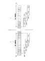
従来、上記外光型パッシブ方式の測距装置において、図14に示すように、一対のラインセンサSR,SLの各受光エリアを、例えば3つの小さいエリア(以下、測距エリアという。)AR(1),AR(2),AR(3)に分割し、各測距エリアAR(1)〜AR(3)毎に、一方の画像(以下、第1の画像という。)に対する他方の画像(以下、第2の画像という。)の位置ずれを検出するとともに、この位置ずれを用いて被写体距離を算出し、更にこれらの各測距エリアAR(1)〜AR(3)毎の被写体距離を用いてAF制御(自動焦点調節制御)を行なうための被写体距離を算出する、いわゆる多分割測距方法が提案されている。
【0005】
各測距エリアにおける第1の画像に対する第2の画像の位置ずれはラインセンサSRの測距エリアAR(i)(i=1,2,3)内の第1の画像PR(i)とラインセンサSLの測距エリアAR(i)内の第2の画像PL(i)とをそれぞれ交互に1画素ずつシフトさせて比較し、第1の画像PR(i)と第2の画像PL(i)との一致度が最も大きくなるシフト量により検出される。
【0006】
なお、第1の画像PR(i)と第2の画像PL(i)との一致度は画像をシフトする毎に対応する画素位置の画素データのレベル差(濃度差)の総和Fを算出し、各シフト毎の総和Fを比較することにより判別される。
【0007】
【発明が解決しようとする課題】
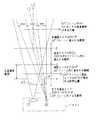
外光型パッシブ方式による測距装置は、図15に示すように、ラインセンサSR,SLからなる測距センサ20の光軸L1がファインダ光学系21の光軸L2と異なるため、測距センサ20の視野θ1とファインダ内に設けられたAFフレームの視野θ2とで空間的パララックスが生じることとなる。このため、近接撮影においては、図16に示すように、測距センサ20の感度領域23のうち、例えば測距エリアAR(1),(2)がAFフレーム22から外れ、通常の多分割測距方式により被写体距離を演算した場合、誤差が生じて信頼性が低下することとなる。
【0008】
従って、かかる場合は演算結果の信頼性低下を防止するため、AFフレーム22に含まれる測距エリアAR(3)を用いてAF制御用の被写体距離を演算することが望ましい。
【0009】
一方、近距離撮影における被写体距離の演算においては、AFフレーム22に含まれる測距エリアAR(3)のみを用いるとした場合、ファインダ光学系21と測距センサ20との相対的な位置関係が一定であれば、少なくともAFフレーム22に対する測距エリアAR(3)の空間的パララックスを小さくすれば、測距可能な最近接距離をより短くできるという性能向上が可能になる(図15参照)。
【0010】
かかる測距性能の向上を目的として、測距エリア間のサイズを変えることなく、各測距エリアAR(1)〜AR(3)のサイズを全体的に大きくする方法が考えられるが、このようにすると、測距センサ20の感度領域23がAFフレーム22よりも大きくなるおそれがあるので、この方法には一定の限界がある。
【0011】
本発明は、上記課題に鑑みてなされたものであり、多分割測距における測距可能な最近接距離をより短くすることのできるカメラの測距装置を提供するものである。
【0012】
【課題を解決するための手段】
本発明は、ファインダの光軸上と異なる位置に設けられ、複数の画素をライン状に配列してなる対構造の撮像部を有し、上記ファインダの視野枠内に設けられた測距フレームに含まれる被写体像をそれぞれ上記撮像部で光電変換して取り込む撮像手段と、上記撮像部で取り込まれた一対の被写体像をそれぞれ複数の測距エリアに分割するとともに、対応する一対の測距エリアについて、各測距エリアにそれぞれ含まれる一部の画素データ群を当該測距エリアの範囲内で相対的に互いに離れる方向にシフトすることにより、対応する一対の測距エリア毎に一致度を示す相関値を演算する相関値演算手段と、各測距エリア毎に、上記相関値演算手段で算出された相関値を用いて被写体距離に関する情報を演算する第1の距離情報演算手段と、各測距エリア毎に算出された被写体距離に関する情報を用いて焦点調節のための被写体距離に関する情報を演算する第2の距離情報演算手段とを備えたカメラの測距装置において、上記測距フレームに対する空間的パララックスが最も小さい測距エリアの上記相関値演算における相対的なシフト量が、他の測距エリアよりも大きく設定されているものである(請求項1)。
【0013】
上記構成によれば、被写体の線状画像が撮像手段内の一対の撮像部でそれぞれ取り込まれる。撮像部の各線状画像はそれぞれ複数の測距エリアに分割され、各測距エリア内の線状画像を用いて測距エリア毎に被写体距離に関する情報が演算される。この演算は、一方の撮像部で取り込まれた線状画像(以下、第1線状画像という。)と他方の撮像部で取り込まれた線状画像(以下、第2線状画像という。)とをそれぞれ測距エリア内で交互にライン方向にシフトしつつ、シフトする毎に第1線状画像と第2線状画像との一致度を示す相関値を演算し、相関値が最も小さくなるシフト量を用いて行なわれる。
【0014】
そして、各測距エリア毎に算出された被写体距離に関する情報を用いて焦点調節のための被写体距離の情報が演算される。
【0015】
各測距エリアの相関値演算における第1線状画像及び第2線状画像のシフト量は測距フレームに対する空間的パララックスが最も小さい測距エリアが他の測距エリアよりも大きくなるように、すなわち、実質的にこの測距エリアのサイズが他の測距エリアのサイズよりも広くなるように設定されている。
【0016】
これにより、各測距エリアのシフト数を同一とする従来の多分割測距方式の測距装置に対して、測距フレームに対する空間的パララックスが最も小さい測距エリアのみシフト量を増加し、この測距エリアのサイズを増加した場合、サイズを増加した分、この測距エリアの測距可能な近接距離が従来の測距可能な近接距離よりも短くなる。
【0017】
また、上記従来の多分割測距方式の測距装置に対して、測距フレームに対する空間的パララックスが最も小さい測距エリア以外の測距エリアのみシフト数を減少し、この測距エリアのサイズを縮小した場合、サイズを縮小した分、これらの測距エリアの相関値演算時間が従来のものより短くなる。
【0018】
また、上記カメラの測距装置において、上記第1の距離情報演算手段で算出された被写体距離に関する情報を用いて被写体距離が予め設定された近接距離以内であるか否かを判別する判別手段と、上記判別手段により被写体距離が上記所定の近接距離以内であるとき、上記第2の距離情報演算手段は、前記シフト数が大きく設定された測距エリアの被写体距離に関する情報を用いて焦点調節のための被写体距離に関する情報を演算するものである。
【0019】
上記構成によれば、第1の距離情報演算手段で算出された被写体距離に関する情報を用いて被写体距離が予め設定された近接距離以内であるか否かが判別され、被写体距離が上記所定の近接距離以内であるとき、焦点調節のための被写体距離に関する情報は前記シフト数が大きく設定された測距エリアの被写体距離に関する情報を用いて演算される。
【0020】
【発明の実施の形態】
図1は、本発明に係る測距装置を備えたカメラの正面図である。
【0021】
カメラ1はカメラ本体2の正面略中央にズームレンズからなる撮影レンズ3を有し、その斜め左上部に測光部4が設けられている。撮影レンズ3のレンズ系内には複数枚のシャッタ羽根を組み合わせてなるレンズシャッタが設けられている。また、撮影レンズ3の上部に測距部5が設けられ、その右側のファインダー対物窓6が設けられ、更にファインダー対物窓6の下部に測距用の補助光発光窓7が設けられている。また、カメラ本体2の右端上部にポップアップタイプの内蔵フラッシュ8が設けられている。
【0022】
測光部4はSPC等から成る受光素子を備え、被写体からの光を受光して被写体の輝度データを算出するものである。
【0023】
測距部5は、図2に示すように、ファインダーの視野枠9の略中央に感度領域91を有するAFセンサ10を備え、上記感度領域91に含まれる被写体からの反射光を受光して得られる画像情報を用いてカメラ1から被写体までの距離(以下、被写体距離という。)D(m)を検出するものである。なお、ファインダー内には視野枠9の中央に測距エリアを示すAFフレーム92が表示されている。撮影者は焦点を合わせたい被写体がAFフレーム92内に含まれるようにフレーミングを行ない、シャッタボタンを半押しすることによりその被写体に対して焦点調節を行なうことができるようになっている。
【0024】
測距部5は、図3に示すように、主として一対のラインイメージセンサ101,102からなるAFセンサ10とこれらのラインイメージセンサ101,102の前方位置にそれぞれ配置された一対の微小レンズアレイ111,112からなるレンズ系11とからなる。ラインイメージセンサ101,102は同一ライン上に所定の間隔を設けて配置されている。ラインイメージセンサ101,102は、例えば多数の電荷結合素子(以下、画素という。)を線状に配列して成るCCDラインセンサから成り、測距部5は各ラインイメージセンサ101,102で被写体像の一部を撮像し、両撮像画像を構成するデータ(各画素から出力されるデータ。以下、画素データという。)を用いて被写体距離Dを検出する。
【0025】
被写体距離Dはラインイメージセンサ101,102の内、ファインダー光学系12の光軸Lに近い側のラインイメージセンサ101を第1撮像部、光軸Lに遠い側のラインイメージセンサ102を第2撮像部とし、第1撮像部で得られる線状画像と第2撮像部で得られる線状画像とを比較して両画像の相対的な位置のずれ量から算出される。
【0026】
補助光発光窓7は低輝度時に被写体に向けて被写体距離を測定するための補助光を発光する窓で、その内部に近赤外LED等から成る発光素子とこの発光素子からの発光を集光して被写体に投光するレンズとが配置されている。
【0027】
図4は、カメラの測距の制御系を示すブロック図である。
【0028】
同図において、制御回路13はAF(自動焦点調節)、AE(自動露出調節)及びレリーズ等のカメラ1の一連の撮影動作を集中制御するマイクロコンピュータから成る制御回路であって測距の制御も行うものである。制御回路13は積分制御部131、メモリ132及び距離演算部133の測距制御のための処理部を有している。
【0029】
積分制御部131はAFセンサ10の各ラインイメージセンサ101,102の駆動(受光時間(電荷蓄積時間))及び画素データの読出の制御を行うものである。メモリ132はラインイメージセンサ101,102から読み出された画素データを記憶するものである。メモリ132は第1データエリア、第2データエリア及び測距データエリアを有し、第1データエリアにはラインイメージセンサ101で受光された線状画像を構成する画素データが記憶され、第2データエリアにはラインイメージセンサ102で受光された線状画像を構成する画素データが記憶される。また、測距データエリアには第1撮像部で得られた線状画像と第2撮像部で得られた線状画像とを用いて距離演算部133で算出された被写体距離に関するデータ(以下、測距データという。)が記憶される。
【0030】
測距データは、図5に示すように、第1撮像部及び第2撮像部の撮像領域を3つの測距エリアAR(1)〜AR(3)に分割し、各測距エリア毎に演算され、その演算結果が各測距エリアAR(1)〜AR(3)に対応させてメモリ132の測距データエリアに記憶される。なお、図5は第1撮像部及び第2撮像部の撮像領域に設けられた複数の測距エリアの一例を示すもので、測距エリアは3個に限定されるものではなく、2個若しくは4個以上でもよい。
【0031】
各測距エリアAR(i)(i=1,2,3)における測距データの演算は第1撮像部の測距エリアAR(i)内に含まれる一部の隣接する画素データ群(以下、第1画像という。)とこの第1画像と同一の画素数で、第2撮像部の測距エリアAR(i)内に含まれる一部の隣接する画素データ群(以下、第2画像という。)とを交互に画素配列方向に1画素ずつシフトしながら第1画像と第2画像とを比較し、両画像の一致度を示す相関値Fを算出することにより行なわれる。
【0032】
例えば各測距エリアAR(1)の場合、測距エリアAR(1)に含まれる総画素数をN1、演算用の画像を構成する画素数をr(<N1)、演算用の画像をシフトする回数をNS(<N1)とすると、総画素数N1=(NS/2+r)で、図6に示すように、初期状態において、第1撮像部の測距エリアAR(1)にはエリアの右端部に第1画像が含まれる演算領域PR(1)が設定され(従って、左端側にシフト領域QR(1)が設定されている。)、第2撮像部の測距エリアAR(1)にはエリアの左端部に第2画像の演算領域PL(1)が設定され(従って、右端側にシフト領域QL(1)が設定されている。)、まず、シフト数0の状態での第1画像と第2画像の対応する画素位置i(i=0,1,…r−1)における画素データGR(i),GL(i)相互のレベル差ΔD(i)が算出され、更にこれらの総和がシフト数0における相関値F(0)として算出される。なお、相関値F(K)はシフト数Kにおける相関値を示す。
【0033】
すなわち、第1画像及び第2画像を構成する画素データの画素位置iを左側から0,1,2,…r−1とし、第1画像の各画素位置iにおける画素データをGR(i)、第2画像の各画素位置iにおける画素データをGL(i)とすると、ΔD(0)=|GL(0)−GR(0)|,ΔD(1)=|GL(1)−GR(1)|,…ΔD(r-1)=|GL(r-1)−GR(r-1)|が算出され、これらΔD(0),ΔD(1),…ΔD(r-1)を加算して相関値F(0)(=ΔD(0)+ΔD(1)+…+ΔD(r-1))が算出される。
【0034】
続いて、第2撮像部の演算領域PL(1)を1画素だけ右側にシフトして第2画像をずらせ、この第2画像と上記第1画像の両画像について上記と同様の方法で画素データGR(i),GL(i)相互のレベル差ΔD(i)と相関値F(1)とが算出される。すなわち、ΔD(0)=|GL(1)−GR(0)|,ΔD(1)=|GL(2)−GR(1)|,…ΔD(r-1)=|GL(r)−GR(r-1)|が算出され、これらΔD(0),ΔD(1),…ΔD(r-1)を加算してシフト数1の状態での相関値F(1)が算出される。
【0035】
以下、第1撮像部の演算領域PR(1)及び第2撮像部の演算領域PL(1)をそれぞれ交互に1画素ずつ所定の方向にシフトしつつ、シフト数KがNSになるまで、各シフト数Kの状態での相関値F(K)が順次、算出される。
【0036】
上記のように、各測距エリアAR(i)において、演算領域PR(i)及び演算領域PL(i)をそれぞれ右方向と左方向(すなわち、第1撮像部と第2撮像部間の中心Mから両画像がそれぞれ離れる方向)とにシフトして得られる相互に所定距離だけ位置のずれた第1画像と第2画像とを比較して測距データの演算が行なわれるので、第1撮像部及び第2撮像部の各測距エリアAR(1)〜AR(3)にはそれぞれ第1画像のシフト領域QR(1)〜QR(3)と第2画像のシフト領域QL(1)〜QL(3)とが設けられている。
【0037】
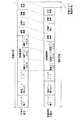
本カメラ1では、測距データの演算において各測距エリアAR(1)〜AR(3)に設けられるシフト領域(QR(1),QL(1))〜(QR(3),QL(3))のサイズを全て同一とせず、図5に示すように、近接距離において、ファインダー光学系のAFフレーム92における視野と測距部5の各測距エリアAR(1)〜AR(3)における視野とのずれが最も小さい(すなわち、ファインダー内のAFフレーム92に対する各測距エリアAR(1)〜AR(3)の空間的パララックスが最も小さい)測距エリアAR(3)のシフト領域(QR(3),QL(3))が他の測距エリアAR(1),AR(2)のシフト領域(QR(1),QL(1)),(QR(2),QL(2))よりも大きくなるようしている。すなわち、シフト領域(QR(1),QL(1))〜(QR(3),QL(3))の画素数をそれぞれm1,m2,m3とすると、m1=m2<m3としている。
【0038】
このように測距エリアAR(3)のシフト領域(QR(3),QL3)のサイズを他の測距領域AR(1),AR(2)のシフト領域(QR(1),QL(1)),(QR(2),QL(2))のサイズより大きくしているのは測距可能な最近接の被写体距離をより短くするためである。
【0039】
すなわち、被写体が最近接したときは、AFフレーム92とAFセンサ10間のパララックスによりAFフレーム92内に測距エリアAR(3)のみが含まれることとなるので、例えば測距エリアAR(1),AR(2)のシフト領域(QR(1),QL(1)),(QR(2),QL(2))のサイズは従来のAFセンサのサイズと同一にし、測距エリアAR(3)のシフト領域(QR(3),QL3)のサイズのみ従来のAFセンサのサイズより大きくすることにより、図7に示すように、測距可能な最近接の被写体距離を短くするようにしている。
【0040】
なお、図7は、各測距エリアAR(1)〜AR(3)の測距可能な最近接の被写体距離を示すもので、ラインAは各測距エリアAR(1)〜AR(3)のシフト領域のサイズm1,m2,m3を同一にした場合の測距可能な最近接の被写体位置を示し、ラインBは測距エリアAR(3)のシフト領域のサイズm3をm3>m1=m2とした場合の測距可能な最近接の被写体位置を示している。また、範囲a1〜a3は各測距エリアAR(1)〜AR(3)のシフト領域のサイズm1,m2,m3を同一にした場合の第1撮像部の各測距エリアAR(1)〜AR(3)の測距範囲を示し、範囲b1〜b3は各測距エリアAR(1)〜AR(3)のシフト領域のサイズm1,m2,m3を同一にした場合の第2撮像部の各測距エリアAR(1)〜AR(3)の測距範囲を示している。
【0041】
各測距エリアAR(1)〜AR(3)の測距可能な最近接の被写体位置は、同図に示すように、第1画像の演算領域PR(1)〜PR(3)及び第2画像の演算領域PL(1)〜PL(3)がそれぞれ測距範囲a1〜a3と測距範囲b1〜b3の最大シフト位置(第1撮像部と第2撮像部間の中心Mから最も離れる位置)にあるとき検出される。測距エリアAR(3)のシフト領域のサイズm3をm3>m1=m2とした場合は測距エリアAR(3)のシフト領域QR(3),QL(3)が拡大して、太線で示すように演算領域PR(3),PL(3)の最大シフト位置がそれぞれ中心Mから離れる方向に移動する(すなわち、演算領域PR(3)と演算領域PL(3)と間の距離が長くなる)ので、第1撮像部の測距エリアAR(3)の光軸方向及び第2撮像部の測距エリアAR(3)の光軸方向が中心M側に変化し、測距可能な最近接の被写体位置がラインAからラインBに短縮される。
【0042】
測距エリアAR(1),AR(2)のシフト領域(QR(1),QL(1)),(QR(2),QL(2))のサイズを従来のAFセンサのサイズと同一にし、測距エリアAR(3)のシフト領域(QR(3),QL(3))のサイズのみ従来のAFセンサ10のサイズより大きくした場合は、測距可能な最近接の被写体位置を従来よりも短くできるが、測距エリアAR(3)の測距データを算出するための画像のシフト数が増加する分、演算時間が若干増加することとなる。
【0043】
これを回避するため、測距エリアAR(3)のシフト領域(QR(3),QL(3))のサイズを大きくした分、測距エリアAR(1),AR(2)のシフト領域(QR(1),QL(1)),(QR(2),QL(2))のサイズを小さくして測距エリアAR(1)〜AR(3)の測距データ演算における全体のシフト数が変化しないようにしてもよい。このようにすると、シフト領域QR(1),QL(2)のサイズを小さくした分、第1撮像部及び第2撮像部のライン方向の長さが短くなるので、AFセンサ10のライン方向のサイズを短くすることができる利点がある。
【0044】
一方、図8に示すように、測距エリアAR(3)のシフト領域(QR(3),QL(3))のサイズを従来のAFセンサのサイズと同一にし、測距エリアAR(1),AR(2)のシフト領域(QR(1),QL(1)),(QR(2),QL(2))のサイズを従来のAFセンサのサイズ(図8の点線で示すサイズ)より小さくして、測距エリアAR(3)のシフト領域Q3のサイズm3をm3>m1=m2とすることもできるが、この場合は測距エリアAR(3)のシフト領域(QR(3),QL(3))が従来のAFセンサのサイズと同一であるため、測距可能な最近接の被写体位置を短縮することはできない。
【0045】
しかし、この場合は測距エリアAR(1),AR(2)のシフト領域(QR(1),QL(1)),(QR(2),QL(2))のサイズを従来のAFセンサのサイズより小さくしているので、上記のようにAFセンサ10のライン方向のサイズを短くできる効果があるとともに、図9に示すように、測距エリアAR(1),AR(2)の測距データを算出するための画像のシフト数が減少する分、各測距エリアAR(1),AR(2)毎の測距データの演算時間が短縮でき、多分割測距における全体的な測距時間の短縮が可能になるという効果がある。
【0046】
図4に戻り、距離演算部133は上述した多分割測距演算方法により、各測距エリアAR(1)〜AR(3)毎に、第1画像の画素データと第2画像の画素データとを用いて測距データを算出し、更にこれらのデータを用いてAF制御用の測距データを算出するものである。
【0047】
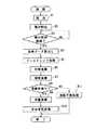
次に、本発明に係るカメラの測距装置の測距動作について、図10のフローチャートを用いて説明する。
【0048】
まず、測光部4により被写体輝度が検出される(#1)。続いて、ラインイメージセンサ101,102の積分動作(受光動作)が開始される(#2)。なお、ラインイメージセンサ101,102の積分時間Tの最大値は撮影準備として許容される測距処理時間から予め設定されており、実際のラインイメージセンサ101,102の積分時間Tは入射光量に応じて変化し、積分時間の最大値以内に受光量が所定値(測距処理に必要な信号レベル)に達すると、その時点で積分動作は終了するようになっている。
【0049】
続いて、所定の積分時間Tが経過した後(#3でYES)、ラインイメージセンサ101,102の各画素データの読出しが行われる(#4)。読み出された画素データは差分変換、重心変換等のフィルタリング処理が行われた後(#9)、図11に示す「相関値演算」のサブルーチンに従って相関演算が行われる(#10)。なお、差分変換は読み出された画素データを、例えば数画素分離れた画素データ間の差分のデータに変換するものである。すなわち、k番目の画素データをG(k)(k=1,2,…n)、離散画素数をqとすると、フィルタリング処理により画素データG(k)は差分データΔG(k)=G(k)−G(k+q)に変換される。また、重心変換は差分データΔG(k)の位置を変換するものである。すなわち、差分データΔG(k)の位置を、例えば(k+q)/2の画素位置を代表するデータとする。このフィルタリング処理はラインイメージセンサ101,102間の感度差に基づく検出誤差を低減するための処理である。
【0050】
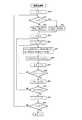
「相関値演算」のサブルーチンに移行すると、まず、測距エリアナンバーをカウントするカウンタiの値が「1」に設定され、測距エリアAR(1)についての相関値F(K)の演算が開始される(#20)。続いて、測距エリアナンバーが「3」であるか否かが判別され(#22)、測距エリアナンバーが「3」以外であれば(#22でNO)、シフト数NSがNS1に設定され(#24)、測距エリアナンバーが「3」であれば(#22でYES)、シフト数NSがNS2(>NS1)に設定される(#26)。
【0051】
続いて、現在のシフト数をカウントするカウンタKの値と画素位置をカウントするカウンタjの値とがそれぞれが「0」に設定され(#26,#28)、ステップ#32〜#38のループ処理によりシフト数K=0における第1画像と第2画像との相関値F(0)が下記演算式(1),(2)で算出される。
【0052】
【数1】
なお、上記(2)式は画素位置jにおける第1画像を構成する画素データGR(j)と第2画像を構成する画素データGL(j)とのレベル差ΔD(j)の演算式であり、上記(1)式は全画素位置jのレベル差ΔD(j)の総和の演算式である。
【0054】
相関値演算においては、各測距エリアAR(1)〜AR(3)の第1撮像部及び第2撮像部に含まれる画素データには、図12(a),(b)に示すように、エリアの左から順番に画素位置を示す番号が設定される。すなわち、各測距エリアAR(i)(i=1,2,3)内の演算領域PR(i),PL(i)に含まれる画素数をr、シフト領域QR(i),QL(i)に含まれる画素数をmとすると、測距エリアAR(i)の総画素数Niは(m+r)であるから第1撮像部及び第2撮像部の各画素データには左端から0,1,2,…(m+r−1)の番号が設定される。
【0055】
一方、相関値F(I)は、図13に示すように、演算領域PR(i)を第1撮像部の右端側から左端側に、また、演算領域PL(i)を第2撮像部の左端側から右端側にそれぞれ交互に1画素ずつシフトして演算されるので、シフト領域QR(i),QL(i)に含まれる画素数mはNS/2(端数切捨て)となる。
【0056】
従って、シフト数K=0においては、演算領域PR(i)の各画素データの番号は、図12(a)に示すように、左端側からm(=NS/2),m+1,…m+r−1となり、演算領域PL(i)の各画素データの番号は、図12(b)に示すように、左端側から0,1,…m−1となる。そして、任意のシフト数Kにおいては、演算領域PR(i)はK/2=s(端数を切り捨てた整数)画素分だけ初期位置から番号が減少する方向にシフトした位置にあり、演算領域PL(i)は(K−s)画素分だけ初期位置から番号が増加する方向にシフトした位置にあるので、演算領域PR(i)の左端側からj番目の画素位置の番号は(NS/2−s+j)となり、演算領域PL(i)の左端側からj番目の画素位置の番号は(K−s+j)となる。
【0057】
上記(2)式において、GL(KL+j)は任意のシフト数Kにおける演算領域PL(i)内の番号(K−s+j)の位置の画素データを示し、GR(SR−KR+j)は任意のシフト数Kにおける演算領域PR(i)内の番号(NS/2−s+j)の位置の画素データを示している。
【0058】
図11に戻り、シフト数K=0における第1画像と第2画像との相関値F(0)の演算が終了すると(#38でYES)、カウント値Kが1だけインクリメントされ(#40)、このカウント値Kがシフト数NSを越えたか否かが判別される(#42)。そして、K≦NSであれば(#42でNO)、ステップ#30に戻り、上記と同様の演算を行なってシフト数K=1における第1画像と第2画像との相関値F(1)の演算が行なわれる。
【0059】
以下、同様の方法でシフト数K=2,3,…における第1画像と第2画像との相関値F(2),F(3),…の演算が行なわれ(#30〜#42のループ)、シフト数K=NSにおける第1画像と第2画像との相関値F(NS)の演算が終了すると(#42でYES)、カウント値iが1だけインクリメントされ(#44)、このカウント値iがシフト数3を越えたか否かが判別される(#46)。
【0060】
そして、i≦3であれば(#46でNO)、ステップ#22に戻り、測距エリアAR(2),AR(3)について順次、相関値F(0)〜F(NS)の演算が行われ、測距エリアAR(3)についての相関値F(0)〜F(NS)の演算が終了すると(#46でYES)、相関値演算が完了し、リターンする。
【0061】
図10に戻り、相関値演算が終了すると、続いて、相関演算の結果とを用いて補間演算が行われる(#7)。補間演算は相関演算の結果の精度を高めるためのものである。すなわち、相関値演算では第1画像と第2画像とを1画素ピッチずつ相対的にシフトしつつ両画像の一致度を示す相関値F(0)〜F(NS)を演算しているので、最も一致度が高くなるシフト量がr画素分と(r+1)画素分との間にある場合は、正確な第1画像と第2画像との位置のずれ量と最小相関値から算出される位置のずれ量との間に誤差を生じることになる。補間演算は、最小相関値F(r)を有する画素位置とその周囲の画素位置との間の推定される相関値Fを補間して上記誤差を低減した第1画像と第2画像との位置のずれ量YMを算出するものである。
【0062】
続いて、各測距エリアAR(1)〜AR(3)毎に算出された相関値の信頼性が判別される(#8)。この信頼性判別は、被写体輝度の輝度レベルによるほか、各測距エリアAR(i)毎にコントラスト値C(i)を算出し、このコントラスト値C(i)に基づいて行われる。コントラスト値C(i)は、例えば測距エリアAR(i)内の隣接する画素間のレベル差の総和(C=Σ|G(j)−G(j+1)|)として算出され、その測距エリアAR(i)内の画像のコントラストの度合いを示すものである。コントラスト値C(i)が小さいほど、画像の濃度変化が少なく、第1画像に一致する第2画像の位置が不明瞭になるので、かかる測距エリアAR(i)の相関値Fの信頼性は低くなる。従って、コントラスト値C(i)を所定の閾値と比較し、この閾値以下の場合、信頼性なしと判断される。なお、コントラスト値C(i)に代えて補間演算で求めたずれ量YMとコントラスト値C(i)との比YM/C(i)を用いて信頼性判定を行ってもよい。
【0063】
いずれかの測距エリアAR(i)において、相関演算の信頼性が「有り」と判断されると(#8でYES)、その測距エリアAR(i)について算出された第1画像と第2画像とのずれ量YMを用いて被写体距離が算出される(#9)。すなわち、ずれ量YMから撮影レンズ3のデフォーカス量が算出され、このデフォーカス量に所定の演算を施して被写体距離が算出される。
【0064】
続いて、多点測距処理が行われた後(#10)、処理を終了する。なお、多点測距処理は、信頼性有りと判断された測距エリアAR(i)の内、適切な測距エリアAR(i)の被写体距離のデータを用いてAF制御用の最終的な被写体距離のデータの算出を行うものである。この算出は、例えば信頼性有りと判断された測距エリアAR(i)の内、最近接の被写体を有する測距エリアAR(i)の被写体距離のデータを抽出することにより、或いは、複数の測距エリアAR(i)の被写体距離のデータを平均化することにより行われる。
【0065】
また、上述したように、被写体が近距離にあるときは、AFフレーム92内には測距エリアAR(3)のみが含まれ、測距エリアAR(1),AR(2)を考慮すると、演算結果の信頼性が低下するおそれがあるので、例えば信頼性有りと判断された測距エリアAR(i)の被写体距離を所定の閾値と比較して被写体の位置が所定の近接距離以内に有るか否かを判別し、被写体が所定の近接距離内にある場合は、測距エリアAR(3)の被写体距離のデータを優先的に選択してAF制御用の被写体距離のデータが算出される。
【0066】
一方、全ての測距エリアAR(1)〜AR(3)について、相関値Fの信頼性が「無し」と判断されると(#8でNO)、例えば警告表示等の測距不能処理が行なわれて(#11)、処理を終了する。
【0067】
なお、上記多点測距処理では、近接距離においては、自動的に測距エリアAR(3)を優先的に使用してAF制御用の被写体距離のデータを算出するようにしているが、例えばカメラ1に測距エリアAR(3)の選択ボタンを設定しておき、撮影者が近接距離の被写体を撮影するとき、選択ボタンを操作して測距エリアAR(3)を選択するようにしてもよい。この場合、測距エリアAR(3)のみについて測距処理を行なうようにすれば、測距時間を短縮することができる。
【0068】
【発明の効果】
以上説明したように、本発明によれば、外光型パッシブ方式の多分割測距方式によるカメラの測距装置において、撮像手段の一対の撮像部に設けられた複数の測距エリアのうち、測距フレームに対する空間的パララックスが最も小さい測距エリアの、相関値演算における相対的なシフト数を、他の測距エリアよりも大きく設定したので、例えば他の測距エリアのシフト数を従来の測距装置と同一とし、測距フレームに対する空間的パララックスが最も小さい測距エリアのみシフト数を増加することにより、この測距エリアの測距可能な近接距離がシフト数を増加しなかった場合よりも短くなり、この結果、従来の測距装置よりも測距可能な最近接距離を短縮することができる。
【0069】
また、測距フレームに対する空間的パララックスが最も小さい測距エリアのシフト数を従来の測距装置と同一とし、他の測距エリアのシフト数を減少することにより、これらの測距エリアにおける相関値演算の演算時間が短くなり、この結果、従来の測距装置よりも多分割測距の測距時間を短縮することができる。
【0070】
また、各測距エリアで算出された被写体距離に関する情報から被写体が所定の近接距離以内にあると判別されたときは、測距フレームに対する空間的パララックスが最も小さい測距エリアの被写体距離に関する情報を用いて焦点調節のための被写体距離に関する情報を演算するようにしたので、AFフレームから外れた測距エリアの被写体距離の情報により測距結果の信頼性が低下することがない。
【図面の簡単な説明】
【図1】本発明に係る測距装置を備えたカメラの正面図である。
【図2】撮影画面内のAFセンサの感度領域を示す図である。
【図3】測距部の構成を示す図である。
【図4】本発明に係る測距装置の制御系のブロック図である。
【図5】AFセンサの第1撮像部と第2撮像部に設けられた複数の測距エリアの一例を示す図である。
【図6】各測距エリアの第1撮像部及び第2撮像部に設けられた演算領域の初期位置と相関値演算における演算領域のシフト方向を示す図である。
【図7】各測距エリアの測距可能な最近接の被写体の位置を示す図である。
【図8】AFセンサの第1撮像部と第2撮像部に設けられた複数の測距エリアの他の例を示す図である。
【図9】測距時間の短縮効果を示す図である。
【図10】本発明に係る測距装置の測距動作を示すフローチャートである。
【図11】「相関値演算」のサブルーチンのフローチャートである。
【図12】測距エリアに含まれる画素データに付与されるアドレスナンバーを示す図で、(a)は第1撮像部の測距エリアに対するもの、(b)は第2撮像部の測距エリアに対するものである。
【図13】第1画像及び第2画像を交互にそれぞれ1画素ずつシフトして各シフト毎に相関値演算を行なう方法を示す図である。
【図14】外光型パッシブ方式における多分割測距方法を示す図である。
【図15】空間的パララックスに基づくファインダー内に設けられたAFフレームと測距センサの感度領域間のずれと被写体距離との関係を示す図である。
【図16】空間的パララックスに基づくファインダー内に設けられたAFフレームと測距センサの感度領域とのずれを示す図である。
【符号の説明】
1 カメラ
2 カメラ本体
3 撮影レンズ
4 測光部
5 測距部
6 ファインダー対物窓
7 補助光発光窓
8 内蔵フラッシュ
9 視野枠
91 感度領域
92 AFフレーム
10 AFセンサ(撮像手段)
101,102 ラインイメージセンサ
11 レンズ系
111,112 レンズアレイ
12 ファインダー光学系
13 制御回路(判定手段)
131 積分制御部
132 メモリ
133 距離演算部(相関値演算手段、第1、第2の距離情報演算手段)[0001]
TECHNICAL FIELD OF THE INVENTION
The present invention is based on a so-called external light type passive system that detects information on the distance to a subject by using a subject image obtained by receiving reflected light from the subject included in a distance measurement frame provided in a finder. The present invention relates to a camera ranging device.
[0002]
[Prior art]
In a lens-integrated camera such as a compact camera, a distance measuring device that forms a pair of line sensors and an object image included in a distance measuring frame provided in the viewfinder on these line sensors adjacent to a finder optical system. An external light type passive distance measuring device including an objective lens is provided.
[0003]
The distance measuring principle of the above distance measuring device is basically based on a triangular distance measuring method, and detects a relative displacement amount of an image captured by one line sensor with respect to an image captured by the other line sensor. The object distance is calculated using the amount of deviation.
[0004]
Conventionally, in the external light type passive distance measuring apparatus, as shown in FIG. 14, each light receiving area of the pair of line sensors SR and SL is, for example, three small areas (hereinafter, referred to as distance measuring areas) AR ( 1), AR (2), and AR (3), and for each of the distance measurement areas AR (1) to AR (3), the other image (hereinafter referred to as a first image) with respect to one image (hereinafter, referred to as a first image). In the following, the position shift of the second image is detected, the subject distance is calculated using the position shift, and the subject distance for each of the distance measurement areas AR (1) to AR (3) is calculated. A so-called multi-division ranging method for calculating a subject distance for performing AF control (automatic focus adjustment control) using the same has been proposed.
[0005]
The displacement of the second image with respect to the first image in each ranging area is equal to the position of the first image PR (i) in the ranging area AR (i) (i = 1, 2, 3) of the line sensor SR. The second image PL (i) in the distance measurement area AR (i) of the sensor SL is alternately shifted by one pixel and compared, and the first image PR (i) and the second image PL (i) are compared. ) Is detected based on the shift amount at which the degree of coincidence with) becomes largest.
[0006]
The degree of coincidence between the first image PR (i) and the second image PL (i) is calculated by calculating the total sum F of the level difference (density difference) of the pixel data at the corresponding pixel position every time the image is shifted. , Is determined by comparing the sum F of each shift.
[0007]
[Problems to be solved by the invention]
As shown in FIG. 15, the distance measuring device using the passive light type external light system has the optical axis L1 of the
[0008]
Therefore, in such a case, it is desirable to calculate the subject distance for AF control using the ranging area AR (3) included in the
[0009]
On the other hand, in the calculation of the subject distance in the close-up shooting, when only the distance measurement area AR (3) included in the
[0010]
For the purpose of improving the ranging performance, a method of increasing the size of each ranging area AR (1) to AR (3) as a whole without changing the size between the ranging areas is considered. In this case, the
[0011]
The present invention has been made in view of the above problems, and, Many An object of the present invention is to provide a camera distance measuring apparatus capable of further shortening the closest distance that can be measured in divided distance measurement.
[0012]
[Means for Solving the Problems]
The present invention includes a paired imaging unit provided at a position different from the optical axis of the finder and a plurality of pixels arranged in a line, and a distance measurement frame provided in a field frame of the finder. An imaging unit that photoelectrically converts and captures the subject images included in the imaging unit, and divides a pair of subject images captured by the imaging unit into a plurality of distance measurement areas, and a corresponding pair of distance measurement areas. The correlation indicating the degree of coincidence for each of a pair of corresponding distance measurement areas by shifting a part of the pixel data groups included in each of the distance measurement areas in directions relatively away from each other within the range of the distance measurement area. A first distance information calculating means for calculating information on a subject distance using the correlation value calculated by the correlation value calculating means for each distance measuring area; A second distance information calculating means for calculating information on a subject distance for focus adjustment using information on a subject distance calculated for each area; The relative shift amount in the correlation value calculation of the distance measurement area having the smallest parallax is set to be larger than the other distance measurement areas.
[0013]
According to the above configuration, the linear image of the subject is captured by the pair of imaging units in the imaging unit. Each linear image of the imaging unit is divided into a plurality of distance measurement areas, and information on the subject distance is calculated for each distance measurement area using the linear image in each distance measurement area. This calculation is performed on a linear image (hereinafter, referred to as a first linear image) captured by one imaging unit and a linear image (hereinafter, referred to as a second linear image) captured by the other imaging unit. Are alternately shifted in the line direction within the ranging area, and each time the shift is performed, a correlation value indicating the degree of coincidence between the first linear image and the second linear image is calculated. It is performed using the amount.
[0014]
Then, information on the subject distance for focus adjustment is calculated using the information on the subject distance calculated for each ranging area.
[0015]
The shift amount of the first linear image and the second linear image in the correlation value calculation of each ranging area is set such that the ranging area having the smallest spatial parallax with respect to the ranging frame is larger than the other ranging areas. That is, the size of the distance measurement area is set to be substantially larger than the sizes of the other distance measurement areas.
[0016]
Thereby, for the conventional multi-division ranging system in which the number of shifts in each ranging area is the same, the shift amount is increased only in the ranging area having the smallest spatial parallax with respect to the ranging frame, When the size of the distance measurement area is increased, the distance that can be measured in the distance measurement area becomes shorter than the conventional distance that can be measured by the increase in size.
[0017]
Further, in comparison with the conventional multi-division ranging system, the number of shifts is reduced only in the ranging region other than the ranging region having the smallest spatial parallax for the ranging frame, and the size of the ranging region is reduced. Is reduced, the time required to calculate the correlation value of these distance measurement areas becomes shorter than that of the conventional one by the reduced size.
[0018]
In the distance measuring device for the camera, a determining means for determining whether or not the subject distance is within a preset proximity distance using the information on the subject distance calculated by the first distance information calculating means. When the object distance is within the predetermined proximity distance by the determination means, the second distance information calculating means performs focus adjustment using information on the object distance of the distance measurement area in which the shift number is set to be large. To calculate information about the subject distance.
[0019]
According to the above configuration, it is determined whether or not the subject distance is within a preset proximity distance by using the information on the subject distance calculated by the first distance information calculating means, and the subject distance is determined to be the predetermined proximity. When the distance is within the distance, the information on the subject distance for focus adjustment is calculated using the information on the subject distance in the ranging area where the shift number is set large.
[0020]
BEST MODE FOR CARRYING OUT THE INVENTION
FIG. 1 is a front view of a camera provided with a distance measuring device according to the present invention.
[0021]
The
[0022]
The
[0023]
As shown in FIG. 2, the
[0024]
As shown in FIG. 3, the
[0025]
The subject distance D of the
[0026]
The auxiliary
[0027]
FIG. 4 is a block diagram showing a control system for distance measurement of the camera.
[0028]
In FIG. 1, a
[0029]
The
[0030]
As shown in FIG. 5, the distance measurement data is obtained by dividing the imaging regions of the first imaging unit and the second imaging unit into three distance measurement areas AR (1) to AR (3), and calculating each of the distance measurement areas. The calculation result is stored in the distance measurement data area of the
[0031]
The calculation of the distance measurement data in each of the distance measurement areas AR (i) (i = 1, 2, 3) is performed by using a part of a group of adjacent pixel data (hereinafter, referred to as a pixel data group) included in the distance measurement area AR (i) of the first imaging unit. , A first image) and a part of adjacent pixel data groups (hereinafter, referred to as a second image) included in the ranging area AR (i) of the second imaging unit with the same number of pixels as the first image. .) Are alternately shifted one pixel at a time in the pixel array direction, the first image and the second image are compared, and a correlation value F indicating the degree of coincidence between the two images is calculated.
[0032]
For example, in the case of each ranging area AR (1), the total number of pixels included in the ranging area AR (1) is N1, the number of pixels forming the image for calculation is r (<N1), and the image for calculation is shifted. Assuming that the number of times of performing is NS (<N1), the total number of pixels N1 = (NS / 2 + r), and as shown in FIG. 6, in the initial state, the distance measurement area AR (1) of the first image pickup unit has The calculation area PR (1) including the first image is set at the right end (therefore, the shift area QR (1) is set at the left end), and the distance measurement area AR (1) of the second imaging unit. , The calculation area PL (1) of the second image is set at the left end of the area (therefore, the shift area QL (1) is set at the right end). The level difference ΔD (i) between the pixel data GR (i) and GL (i) at the corresponding pixel position i (i = 0, 1,..., R−1) between the first image and the second image. Is calculated and further calculates the sum of these as the correlation value F (0) in the
[0033]
That is, pixel positions i of pixel data constituting the first image and the second image are set to 0, 1, 2, ... r-1 from the left, and pixel data at each pixel position i of the first image is GR (i), Assuming that pixel data at each pixel position i of the second image is GL (i), ΔD (0) = | GL (0) −GR (0) |, ΔD (1) = | GL (1) −GR (1) ... ΔD (r−1) = | GL (r−1) −GR (r−1) |, and these ΔD (0), ΔD (1),. Then, a correlation value F (0) (= ΔD (0) + ΔD (1) +... + ΔD (r−1)) is calculated.
[0034]
Subsequently, the calculation area PL (1) of the second imaging unit is shifted to the right by one pixel to shift the second image, and the pixel data of both the second image and the first image are processed in the same manner as described above. A level difference ΔD (i) between GR (i) and GL (i) and a correlation value F (1) are calculated. That is, ΔD (0) = | GL (1) −GR (0) |, ΔD (1) = | GL (2) −GR (1) |,... ΔD (r−1) = | GL (r) − GR (r-1) | is calculated, and these .DELTA.D (0), .DELTA.D (1),..., .DELTA.D (r-1) are added to calculate the correlation value F (1) in the state of the
[0035]
Hereinafter, while the calculation region PR (1) of the first imaging unit and the calculation region PL (1) of the second imaging unit are alternately shifted one pixel at a time in the predetermined direction, the calculation region PR (1) until the shift number K becomes NS. The correlation value F (K) in the state of the shift number K is sequentially calculated.
[0036]
As described above, in each of the distance measurement areas AR (i), the calculation area PR (i) and the calculation area PL (i) are respectively shifted rightward and leftward (that is, the center between the first imaging unit and the second imaging unit). The distance measurement data is calculated by comparing the first image and the second image which are shifted by a predetermined distance from each other and are obtained by shifting the two images (in the direction in which both images are separated from M). In each of the distance measurement areas AR (1) to AR (3) of the unit and the second imaging unit, the shift areas QR (1) to QR (3) of the first image and the shift areas QL (1) to QL (3).
[0037]
In the
[0038]
Thus, the size of the shift area (QR (3), QL3) of the distance measurement area AR (3) is changed to the shift area (QR (1), QL (1) of the other distance measurement areas AR (1), AR (2). )), (QR (2), QL (2))Is This is in order to further shorten the distance of the closest subject that can be distanced.
[0039]
Ie, When the object is closest, only the distance measurement area AR (3) is included in the
[0040]
FIG. 7 shows the closest object distance that can be measured in each of the distance measurement areas AR (1) to AR (3), and a line A indicates each of the distance measurement areas AR (1) to AR (3). Indicates the closest subject position at which distance measurement is possible when the sizes m1, m2, and m3 of the shift area are the same, and the line B indicates the size m3 of the shift area of the distance measurement area AR (3) as m3> m1 = m2 Indicates the closest subject position at which distance measurement is possible. The ranges a1 to a3 correspond to the distance measurement areas AR (1) to AR (1) of the first imaging unit when the sizes m1, m2, and m3 of the shift areas of the distance measurement areas AR (1) to AR (3) are the same. AR (3) indicates the distance measurement range. Ranges b1 to b3 are the ranges of the second imaging unit when the sizes m1, m2, and m3 of the shift areas of the distance measurement areas AR (1) to AR (3) are the same. The distance measurement ranges of the distance measurement areas AR (1) to AR (3) are shown.
[0041]
As shown in the figure, the closest subject positions in each of the distance measurement areas AR (1) to AR (3) that can be measured are the calculation areas PR (1) to PR (3) and the second The calculation areas PL (1) to PL (3) of the image are the maximum shift positions of the distance measurement ranges a1 to a3 and the distance measurement ranges b1 to b3 (the positions farthest from the center M between the first imaging unit and the second imaging unit). ) Is detected. When the size m3 of the shift area of the distance measurement area AR (3) is set to m3> m1 = m2, the shift areas QR (3) and QL (3) of the distance measurement area AR (3) are enlarged and indicated by thick lines. As described above, the maximum shift positions of calculation regions PR (3) and PL (3) move in directions away from center M (that is, the distance between calculation region PR (3) and calculation region PL (3) becomes longer). Therefore, the optical axis direction of the distance measurement area AR (3) of the first imaging unit and the optical axis direction of the distance measurement area AR (3) of the second imaging unit change to the center M side, and the closest distance measurement is possible. Is reduced from line A to line B.
[0042]
The size of the shift areas (QR (1), QL (1)) and (QR (2), QL (2)) of the distance measurement areas AR (1) and AR (2) are made the same as the size of the conventional AF sensor. If only the size of the shift area (QR (3), QL (3)) of the distance measurement area AR (3) is larger than the size of the
[0043]
In order to avoid this, the shift area (QR (3), QL (3)) of the distance measurement area AR (3) is increased by the size of the shift area (AR (1), AR (2)). QR (1), QL (1)) and (QR (2), QL (2)) are reduced in size to reduce the total number of shifts in the distance measurement data calculation of the distance measurement areas AR (1) to AR (3). May not be changed. By doing so, the length of the first imaging unit and the second imaging unit in the line direction is reduced by the reduced size of the shift regions QR (1) and QL (2). There is an advantage that the size can be shortened.
[0044]
On the other hand, as shown in FIG. 8, the size of the shift area (QR (3), QL (3)) of the distance measurement area AR (3) is made the same as the size of the conventional AF sensor, and the distance measurement area AR (1) , AR (2) shift regions (QR (1), QL (1)) and (QR (2), QL (2)) are obtained from the size of the conventional AF sensor (the size indicated by the dotted line in FIG. 8). The size m3 of the shift area Q3 of the distance measurement area AR (3) can be set to m3> m1 = m2. In this case, the shift area (QR (3), QL (3)) is the same as the size of the conventional AF sensor, so that it is not possible to shorten the position of the closest subject that can be measured.
[0045]
However, in this case, the sizes of the shift areas (QR (1), QL (1)) and (QR (2), QL (2)) of the distance measurement areas AR (1) and AR (2) are changed to those of the conventional AF sensor. Since the size of the
[0046]
Referring back to FIG. 4, the
[0047]
Next, the ranging operation of the ranging device for a camera according to the present invention will be described with reference to the flowchart of FIG.
[0048]
First, the luminance of the subject is detected by the photometry unit 4 (# 1). Subsequently, the integration operation (light receiving operation) of the
[0049]
Subsequently, after a predetermined integration time T has elapsed (YES in # 3), each pixel data of the
[0050]
When the process proceeds to the “correlation value calculation” subroutine, first, the value of the counter i for counting the distance measurement area number is set to “1”, and the calculation of the correlation value F (K) for the distance measurement area AR (1) is performed. It is started (# 20). Subsequently, it is determined whether or not the ranging area number is "3"(# 22). If the ranging area number is other than "3" (NO in # 22), the shift number NS is set to NS1. If the distance measurement area number is "3" (YES in # 22), the shift number NS is set to NS2 (> NS1) (# 26).
[0051]
Subsequently, the value of the counter K for counting the current shift number and the value of the counter j for counting the pixel position are respectively set to "0"(# 26, # 28), and a loop of steps # 32 to # 38 is performed. By the processing, the correlation value F (0) between the first image and the second image at the shift number K = 0 is calculated by the following arithmetic expressions (1) and (2).
[0052]
(Equation 1)
The above equation (2) is an equation for calculating the level difference ΔD (j) between the pixel data GR (j) constituting the first image and the pixel data GL (j) constituting the second image at the pixel position j. The above equation (1) is an equation for calculating the sum of the level differences ΔD (j) at all pixel positions j.
[0054]
In the correlation value calculation, the pixel data included in the first imaging unit and the second imaging unit in each of the distance measurement areas AR (1) to AR (3) is as shown in FIGS. , A number indicating a pixel position is set in order from the left of the area. That is, the number of pixels included in the calculation areas PR (i) and PL (i) in each distance measurement area AR (i) (i = 1, 2, 3) is represented by r, and the shift areas QR (i) and QL (i). )) Is m, the total number of pixels Ni in the distance measurement area AR (i) is (m + r), so that the pixel data of the first imaging unit and the second imaging unit include 0, 1 from the left end. , 2,... (M + r-1) are set.
[0055]
On the other hand, as shown in FIG. 13, the correlation value F (I) is obtained by calculating the calculation area PR (i) from the right end to the left end of the first imaging unit, and calculating the calculation area PL (i) from the second imaging unit. Since the calculation is performed by shifting one pixel at a time from the left end side to the right end side, the number m of pixels included in the shift regions QR (i) and QL (i) is NS / 2 (fraction rounded down).
[0056]
Therefore, when the shift number K = 0, the numbers of the respective pixel data in the operation area PR (i) are m (= NS / 2), m + 1,..., M + r− from the left end as shown in FIG. 1 and the numbers of the respective pixel data in the operation area PL (i) are 0, 1,..., M−1 from the left end side as shown in FIG. At an arbitrary shift number K, the operation area PR (i) is located at a position shifted from the initial position by K / 2 = s (integer rounded down) pixels in the direction of decreasing the number, and the operation area PL Since (i) is located at a position shifted from the initial position by (Ks) pixels in the direction in which the number increases, the number of the j-th pixel position from the left end of the calculation region PR (i) is (NS / 2). −s + j), and the number of the j-th pixel position from the left end side of the calculation area PL (i) is (K−s + j).
[0057]
In the above equation (2), GL (KL + j) indicates pixel data at the position of the number (Ks + j) in the operation area PL (i) at an arbitrary shift number K, and GR (SR-KR + j) indicates an arbitrary shift The pixel data at the position of the number (NS / 2-s + j) in the calculation region PR (i) in the number K is shown.
[0058]
Returning to FIG. 11, when the calculation of the correlation value F (0) between the first image and the second image at the shift number K = 0 is completed (YES in # 38), the count value K is incremented by 1 (# 40). It is determined whether or not the count value K has exceeded the shift number NS (# 42). If K ≦ NS (NO in # 42), the process returns to step # 30, and performs the same calculation as above to calculate the correlation value F (1) between the first image and the second image at the shift number K = 1. Is performed.
[0059]
Hereinafter, the calculation of the correlation values F (2), F (3),... Between the first image and the second image at the shift numbers K = 2, 3,. When the calculation of the correlation value F (NS) between the first image and the second image at the shift number K = NS is completed (YES in # 42), the count value i is incremented by 1 (# 44). It is determined whether or not the count value i has exceeded the shift number 3 (# 46).
[0060]
If i ≦ 3 (NO in # 46), the process returns to step # 22, and the calculation of the correlation values F (0) to F (NS) is sequentially performed on the distance measurement areas AR (2) and AR (3). When the calculation of the correlation values F (0) to F (NS) for the distance measurement area AR (3) is completed (YES in # 46), the calculation of the correlation value is completed, and the routine returns.
[0061]
Returning to FIG. 10, when the correlation value calculation is completed, subsequently, an interpolation calculation is performed using the result of the correlation calculation (# 7). The interpolation operation is for improving the accuracy of the result of the correlation operation. That is, in the correlation value calculation, since the first image and the second image are relatively shifted by one pixel pitch while calculating the correlation values F (0) to F (NS) indicating the degree of coincidence between the two images, When the shift amount that provides the highest degree of coincidence is between r pixels and (r + 1) pixels, an accurate position shift between the first image and the second image and the position calculated from the minimum correlation value An error occurs between the shift amount and the shift amount. The interpolation operation interpolates the estimated correlation value F between the pixel position having the minimum correlation value F (r) and the surrounding pixel positions to reduce the error between the first image and the second image. Deviation amount YM Is calculated.
[0062]
Subsequently, the reliability of the correlation value calculated for each of the distance measurement areas AR (1) to AR (3) is determined (# 8). The reliability determination is performed based on the contrast value C (i) for each distance measurement area AR (i), in addition to the brightness level of the subject brightness, and calculating the contrast value C (i). The contrast value C (i) is calculated, for example, as the sum of the level differences between adjacent pixels in the ranging area AR (i) (C = Σ | G (j) −G (j + 1) |). It shows the degree of contrast of the image in the distance measurement area AR (i). The smaller the contrast value C (i), the smaller the change in density of the image, and the more unclear the position of the second image that matches the first image. Therefore, the reliability of the correlation value F of the distance measurement area AR (i) Is lower. Therefore, the contrast value C (i) is compared with a predetermined threshold value, and when the contrast value is equal to or smaller than this threshold value, it is determined that there is no reliability. Note that, instead of the contrast value C (i), the shift amount Y obtained by interpolation calculationM Y of the contrast value and the contrast value C (i)M The reliability determination may be performed using / C (i).
[0063]
If it is determined that the reliability of the correlation calculation is “present” in any of the distance measurement areas AR (i) (YES in # 8), the first image and the second image calculated for the distance measurement area AR (i) are determined. Amount of deviation Y from two imagesM Is used to calculate the subject distance (# 9). That is, the deviation amount YM , The defocus amount of the photographing
[0064]
Subsequently, after the multipoint ranging processing is performed (# 10), the processing is terminated. Note that the multi-point distance measurement process uses the data of the subject distance of the appropriate distance measurement area AR (i) among the distance measurement areas AR (i) determined to be reliable, and performs the final AF control. The object distance data is calculated. This calculation is performed, for example, by extracting data of the subject distance of the ranging area AR (i) having the closest subject from among the ranging areas AR (i) determined to be reliable, or This is performed by averaging the data of the subject distance in the distance measurement area AR (i).
[0065]
As described above, when the subject is at a short distance, the
[0066]
On the other hand, if it is determined that the reliability of the correlation value F is “none” for all the distance measurement areas AR (1) to AR (3) (NO in # 8), for example, a distance measurement impossible process such as a warning display is performed. Is performed (# 11), and the process ends.
[0067]
In the multi-point distance measurement process, at the close distance, data of the subject distance for AF control is automatically calculated by preferentially using the distance measurement area AR (3). A selection button of the ranging area AR (3) is set on the
[0068]
【The invention's effect】
As described above, according to the present invention, in a range finder for a camera using a multi-division ranging system of an external light type passive system, among a plurality of ranging areas provided in a pair of imaging units of an imaging unit, The relative number of shifts in the correlation value calculation of the distance measurement area with the smallest spatial parallax to the distance measurement frame is set to be larger than that of the other distance measurement areas. By increasing the number of shifts only in the distance measurement area having the smallest spatial parallax with respect to the distance measurement frame, the distance that can be measured in this distance measurement area did not increase the number of shifts. As a result, the closest distance that can be measured can be shorter than that of a conventional distance measuring device.
[0069]
In addition, the number of shifts in the ranging area having the smallest spatial parallax with respect to the ranging frame is made the same as that of the conventional ranging apparatus, and the number of shifts in the other ranging areas is reduced, so that the correlation in these ranging areas is reduced. The calculation time of the value calculation is shortened, and as a result, the ranging time of the multi-division ranging can be reduced as compared with the conventional ranging device.
[0070]
When it is determined from the information on the subject distance calculated in each ranging area that the subject is within a predetermined proximity distance, the information on the subject distance in the ranging area with the smallest spatial parallax with respect to the ranging frame is determined. Is used to calculate information on the subject distance for focus adjustment, so that the reliability of the distance measurement result does not decrease due to the information on the subject distance in the ranging area outside the AF frame.
[Brief description of the drawings]
FIG. 1 is a front view of a camera provided with a distance measuring device according to the present invention.
FIG. 2 is a diagram showing a sensitivity area of an AF sensor in a shooting screen.
FIG. 3 is a diagram illustrating a configuration of a distance measuring unit.
FIG. 4 is a block diagram of a control system of the distance measuring apparatus according to the present invention.
FIG. 5 is a diagram illustrating an example of a plurality of ranging areas provided in a first imaging unit and a second imaging unit of the AF sensor.
FIG. 6 is a diagram illustrating an initial position of a calculation area provided in a first imaging unit and a second imaging unit in each ranging area and a shift direction of the calculation area in the correlation value calculation.
FIG. 7 is a diagram illustrating a position of a nearest object that can be measured in each ranging area.
FIG. 8 is a diagram illustrating another example of a plurality of distance measurement areas provided in a first imaging unit and a second imaging unit of the AF sensor.
FIG. 9 is a diagram showing the effect of shortening the distance measurement time.
FIG. 10 is a flowchart showing a distance measuring operation of the distance measuring apparatus according to the present invention.
FIG. 11 is a flowchart of a subroutine of “correlation value calculation”.
12A and 12B are diagrams illustrating address numbers assigned to pixel data included in a distance measurement area, where FIG. 12A is for a distance measurement area of a first imaging unit, and FIG. 12B is a diagram illustrating a distance measurement area of a second imaging unit. Is for
FIG. 13 is a diagram illustrating a method of alternately shifting a first image and a second image by one pixel each and performing a correlation value operation for each shift;
FIG. 14 is a diagram showing a multi-division ranging method in an external light type passive system.
FIG. 15 is a diagram illustrating a relationship between a shift between an AF frame provided in a finder based on spatial parallax and a sensitivity area of a distance measurement sensor and a subject distance.
FIG. 16 is a diagram showing a shift between an AF frame provided in a finder based on spatial parallax and a sensitivity area of a distance measurement sensor.
[Explanation of symbols]
1 camera
2 Camera body
3 Shooting lens
4 Photometry section
5 Distance measuring unit
6 Viewfinder objective window
7 Auxiliary light emission window
8 Built-in flash
9 Field frame
91 Sensitivity area
92 AF frame
10 AF sensor (imaging means)
101,102 line image sensor
11 Lens system
111, 112 Lens array
12 Viewfinder optical system
13 control circuit (judgment means)
131 Integral control unit
132 memory
133 distance calculation unit (correlation value calculation means, first and second distance information calculation means)
Claims (1)
Translated fromJapanesePriority Applications (2)
| Application Number | Priority Date | Filing Date | Title |
|---|---|---|---|
| JP34402396AJP3597657B2 (en) | 1996-12-24 | 1996-12-24 | Camera ranging device |
| US08/997,507US5960219A (en) | 1996-12-24 | 1997-12-23 | Distance metering device and an optical apparatus provided with the same |
Applications Claiming Priority (1)
| Application Number | Priority Date | Filing Date | Title |
|---|---|---|---|
| JP34402396AJP3597657B2 (en) | 1996-12-24 | 1996-12-24 | Camera ranging device |
Publications (2)
| Publication Number | Publication Date |
|---|---|
| JPH10186460A JPH10186460A (en) | 1998-07-14 |
| JP3597657B2true JP3597657B2 (en) | 2004-12-08 |
Family
ID=18366069
Family Applications (1)
| Application Number | Title | Priority Date | Filing Date |
|---|---|---|---|
| JP34402396AExpired - Fee RelatedJP3597657B2 (en) | 1996-12-24 | 1996-12-24 | Camera ranging device |
Country Status (2)
| Country | Link |
|---|---|
| US (1) | US5960219A (en) |
| JP (1) | JP3597657B2 (en) |
Families Citing this family (14)
| Publication number | Priority date | Publication date | Assignee | Title |
|---|---|---|---|---|
| DE19606694C2 (en)* | 1995-02-22 | 2002-12-12 | Asahi Optical Co Ltd | A distance |
| JP3603715B2 (en)* | 2000-01-14 | 2004-12-22 | ミノルタ株式会社 | Distance measuring device and camera equipped with the distance measuring device |
| JP4785266B2 (en)* | 2001-04-17 | 2011-10-05 | キヤノン株式会社 | Multi-point distance measuring device |
| US7179260B2 (en)* | 2003-09-29 | 2007-02-20 | Smith & Nephew, Inc. | Bone plates and bone plate assemblies |
| JP3984138B2 (en)* | 2002-09-27 | 2007-10-03 | フジノン株式会社 | Ranging device and camera equipped with the same |
| JP2004117296A (en)* | 2002-09-27 | 2004-04-15 | Fuji Photo Optical Co Ltd | Distance measuring apparatus and camera provided therewith |
| JP4127808B2 (en)* | 2003-07-23 | 2008-07-30 | フジノン株式会社 | Ranging device |
| US20070242153A1 (en)* | 2006-04-12 | 2007-10-18 | Bei Tang | Method and system for improving image region of interest contrast for object recognition |
| US7467476B2 (en)* | 2006-06-28 | 2008-12-23 | Digavero Philip A | Marking sheet for cutting drywall |
| US7646971B2 (en)* | 2006-11-07 | 2010-01-12 | Sony Ericsson Mobile Communications Ab | Assist light illuminance control |
| JP4802993B2 (en)* | 2006-11-15 | 2011-10-26 | 株式会社ニコン | Correlation calculation method, correlation calculation device, focus detection device, and imaging device |
| US9883164B2 (en)* | 2011-08-03 | 2018-01-30 | Sony Mobile Communications Inc. | Optimizing usage of image sensors in a stereoscopic environment |
| JP6014452B2 (en)* | 2012-10-16 | 2016-10-25 | キヤノン株式会社 | FOCUS DETECTION DEVICE, LENS DEVICE HAVING THE SAME, AND IMAGING DEVICE |
| JP6427027B2 (en)* | 2015-02-13 | 2018-11-21 | キヤノン株式会社 | Focus detection apparatus, control method therefor, imaging apparatus, program, and storage medium |
Family Cites Families (4)
| Publication number | Priority date | Publication date | Assignee | Title |
|---|---|---|---|---|
| US4862204A (en)* | 1985-12-25 | 1989-08-29 | Minolta Camera Kabushiki Kaisha | Focus detection device and method |
| JP3012248B2 (en)* | 1989-05-09 | 2000-02-21 | 旭光学工業株式会社 | Automatic focus detection device and camera equipped with automatic focus detection device |
| US5805939A (en)* | 1994-06-07 | 1998-09-08 | Minolta Co., Ltd. | Camera arranged with a viewfinder system having an optical axis different from that of a distance measuring device |
| JPH08292365A (en)* | 1995-02-22 | 1996-11-05 | Asahi Optical Co Ltd | Automatic focus detector for camera |
- 1996
- 1996-12-24JPJP34402396Apatent/JP3597657B2/ennot_activeExpired - Fee Related
- 1997
- 1997-12-23USUS08/997,507patent/US5960219A/ennot_activeExpired - Lifetime
Also Published As
| Publication number | Publication date |
|---|---|
| JPH10186460A (en) | 1998-07-14 |
| US5960219A (en) | 1999-09-28 |
Similar Documents
| Publication | Publication Date | Title |
|---|---|---|
| EP1975695B1 (en) | Focus detection device, focusing state detection method and imaging apparatus | |
| JP5489641B2 (en) | Focus detection apparatus and control method thereof | |
| US8634015B2 (en) | Image capturing apparatus and method and program for controlling same | |
| JP5207797B2 (en) | Imaging apparatus and control method thereof | |
| US8902349B2 (en) | Image pickup apparatus | |
| JP3597657B2 (en) | Camera ranging device | |
| WO2011004686A1 (en) | Focus detection apparatus | |
| JP5857547B2 (en) | Focus detection device and focus adjustment device | |
| JPH10160410A (en) | Range finder | |
| JP2008310072A (en) | Digital camera | |
| JP4418576B2 (en) | camera | |
| JP7722516B2 (en) | Focus detection device and image sensor | |
| US6901218B2 (en) | Photometer, image sensing device, photometric method, program and recording medium | |
| US6404986B1 (en) | Focus detecting device and apparatus having the same | |
| JP6639326B2 (en) | Control device, imaging device, control method, program, and storage medium | |
| JP3581141B2 (en) | Distance measuring device and camera provided with the same | |
| JP6845912B2 (en) | Imaging device and its control method | |
| JP2004361431A (en) | Imaging unit | |
| JP5332384B2 (en) | Correlation calculation device, focus detection device, and imaging device | |
| JP3963535B2 (en) | Multi-point distance measuring device | |
| JP5338118B2 (en) | Correlation calculation device, focus detection device, and imaging device | |
| JP2018026604A (en) | Imaging apparatus and imaging apparatus system | |
| JP2025156406A (en) | Focus detection device and image sensor | |
| JP2023075146A (en) | Imaging apparatus | |
| JP2004117296A (en) | Distance measuring apparatus and camera provided therewith |
Legal Events
| Date | Code | Title | Description |
|---|---|---|---|
| A131 | Notification of reasons for refusal | Free format text:JAPANESE INTERMEDIATE CODE: A131 Effective date:20040203 | |
| A711 | Notification of change in applicant | Free format text:JAPANESE INTERMEDIATE CODE: A712 Effective date:20040402 | |
| A521 | Request for written amendment filed | Free format text:JAPANESE INTERMEDIATE CODE: A523 Effective date:20040405 | |
| A131 | Notification of reasons for refusal | Free format text:JAPANESE INTERMEDIATE CODE: A131 Effective date:20040601 | |
| A521 | Request for written amendment filed | Free format text:JAPANESE INTERMEDIATE CODE: A821 Effective date:20040720 Free format text:JAPANESE INTERMEDIATE CODE: A523 Effective date:20040720 | |
| RD02 | Notification of acceptance of power of attorney | Free format text:JAPANESE INTERMEDIATE CODE: A7422 Effective date:20040720 | |
| TRDD | Decision of grant or rejection written | ||
| A01 | Written decision to grant a patent or to grant a registration (utility model) | Free format text:JAPANESE INTERMEDIATE CODE: A01 Effective date:20040824 | |
| A61 | First payment of annual fees (during grant procedure) | Free format text:JAPANESE INTERMEDIATE CODE: A61 Effective date:20040909 | |
| R150 | Certificate of patent or registration of utility model | Free format text:JAPANESE INTERMEDIATE CODE: R150 | |
| FPAY | Renewal fee payment (event date is renewal date of database) | Free format text:PAYMENT UNTIL: 20070917 Year of fee payment:3 | |
| FPAY | Renewal fee payment (event date is renewal date of database) | Free format text:PAYMENT UNTIL: 20080917 Year of fee payment:4 | |
| FPAY | Renewal fee payment (event date is renewal date of database) | Free format text:PAYMENT UNTIL: 20080917 Year of fee payment:4 | |
| FPAY | Renewal fee payment (event date is renewal date of database) | Free format text:PAYMENT UNTIL: 20090917 Year of fee payment:5 | |
| FPAY | Renewal fee payment (event date is renewal date of database) | Free format text:PAYMENT UNTIL: 20090917 Year of fee payment:5 | |
| FPAY | Renewal fee payment (event date is renewal date of database) | Free format text:PAYMENT UNTIL: 20100917 Year of fee payment:6 | |
| FPAY | Renewal fee payment (event date is renewal date of database) | Free format text:PAYMENT UNTIL: 20110917 Year of fee payment:7 | |
| FPAY | Renewal fee payment (event date is renewal date of database) | Free format text:PAYMENT UNTIL: 20110917 Year of fee payment:7 | |
| FPAY | Renewal fee payment (event date is renewal date of database) | Free format text:PAYMENT UNTIL: 20120917 Year of fee payment:8 | |
| FPAY | Renewal fee payment (event date is renewal date of database) | Free format text:PAYMENT UNTIL: 20120917 Year of fee payment:8 | |
| FPAY | Renewal fee payment (event date is renewal date of database) | Free format text:PAYMENT UNTIL: 20130917 Year of fee payment:9 | |
| LAPS | Cancellation because of no payment of annual fees |