JP3596307B2 - Imaging device - Google Patents
Imaging deviceDownload PDFInfo
- Publication number
- JP3596307B2 JP3596307B2JP27385598AJP27385598AJP3596307B2JP 3596307 B2JP3596307 B2JP 3596307B2JP 27385598 AJP27385598 AJP 27385598AJP 27385598 AJP27385598 AJP 27385598AJP 3596307 B2JP3596307 B2JP 3596307B2
- Authority
- JP
- Japan
- Prior art keywords
- image
- signal
- images
- recorded
- field
- Prior art date
- Legal status (The legal status is an assumption and is not a legal conclusion. Google has not performed a legal analysis and makes no representation as to the accuracy of the status listed.)
- Expired - Lifetime
Links
- 238000003384imaging methodMethods0.000titleclaimsdescription30
- 238000006243chemical reactionMethods0.000claimsdescription10
- 238000001454recorded imageMethods0.000claimsdescription3
- 101100364854Neurospora crassa (strain ATCC 24698 / 74-OR23-1A / CBS 708.71 / DSM 1257 / FGSC 987) vtr-7 geneProteins0.000description12
- 238000010586diagramMethods0.000description10
- 238000000034methodMethods0.000description8
- SDJLVPMBBFRBLL-UHFFFAOYSA-Ndsp-4Chemical compoundClCCN(CC)CC1=CC=CC=C1BrSDJLVPMBBFRBLL-UHFFFAOYSA-N0.000description6
- 108091022873acetoacetate decarboxylaseProteins0.000description4
- 230000002596correlated effectEffects0.000description4
- 238000005070samplingMethods0.000description4
- 101100162020Mesorhizobium japonicum (strain LMG 29417 / CECT 9101 / MAFF 303099) adc3 geneProteins0.000description3
- 230000001276controlling effectEffects0.000description3
- 108091006418SLC25A13Proteins0.000description2
- 239000004973liquid crystal related substanceSubstances0.000description2
- 101000797092Mesorhizobium japonicum (strain LMG 29417 / CECT 9101 / MAFF 303099) Probable acetoacetate decarboxylase 3Proteins0.000description1
- 230000000295complement effectEffects0.000description1
- 230000000875corresponding effectEffects0.000description1
- 230000000694effectsEffects0.000description1
- 238000009499grossingMethods0.000description1
- 230000008707rearrangementEffects0.000description1
- 238000000926separation methodMethods0.000description1
Images


Classifications
- H—ELECTRICITY
- H04—ELECTRIC COMMUNICATION TECHNIQUE
- H04N—PICTORIAL COMMUNICATION, e.g. TELEVISION
- H04N5/00—Details of television systems
- H04N5/76—Television signal recording
- H04N5/78—Television signal recording using magnetic recording
- H04N5/782—Television signal recording using magnetic recording on tape
- H04N5/783—Adaptations for reproducing at a rate different from the recording rate
- H—ELECTRICITY
- H04—ELECTRIC COMMUNICATION TECHNIQUE
- H04N—PICTORIAL COMMUNICATION, e.g. TELEVISION
- H04N23/00—Cameras or camera modules comprising electronic image sensors; Control thereof
- H04N23/60—Control of cameras or camera modules
- H04N23/63—Control of cameras or camera modules by using electronic viewfinders
- H—ELECTRICITY
- H04—ELECTRIC COMMUNICATION TECHNIQUE
- H04N—PICTORIAL COMMUNICATION, e.g. TELEVISION
- H04N5/00—Details of television systems
- H04N5/76—Television signal recording
- H04N5/765—Interface circuits between an apparatus for recording and another apparatus
- H04N5/77—Interface circuits between an apparatus for recording and another apparatus between a recording apparatus and a television camera
- H04N5/772—Interface circuits between an apparatus for recording and another apparatus between a recording apparatus and a television camera the recording apparatus and the television camera being placed in the same enclosure
- Y—GENERAL TAGGING OF NEW TECHNOLOGICAL DEVELOPMENTS; GENERAL TAGGING OF CROSS-SECTIONAL TECHNOLOGIES SPANNING OVER SEVERAL SECTIONS OF THE IPC; TECHNICAL SUBJECTS COVERED BY FORMER USPC CROSS-REFERENCE ART COLLECTIONS [XRACs] AND DIGESTS
- Y10—TECHNICAL SUBJECTS COVERED BY FORMER USPC
- Y10S—TECHNICAL SUBJECTS COVERED BY FORMER USPC CROSS-REFERENCE ART COLLECTIONS [XRACs] AND DIGESTS
- Y10S358/00—Facsimile and static presentation processing
- Y10S358/906—Hand-held camera with recorder in a single unit
Landscapes
- Engineering & Computer Science (AREA)
- Multimedia (AREA)
- Signal Processing (AREA)
- Television Signal Processing For Recording (AREA)
- Studio Devices (AREA)
- Transforming Light Signals Into Electric Signals (AREA)
Description
Translated fromJapanese【0001】
【発明の属する技術分野】
本発明は、固体撮像素子を用いて被写体の撮像を行うCCDや、ビデオカメラ装置、カメラ装置等の撮像装置に関する。
【0002】
【従来の技術】
今日におけるビデオカメラ装置には、撮像管よりも小型軽量化及びローコスト化等が可能なことから撮像手段として複数の固体撮像素子で形成された固体撮像部(CCDイメージセンサ)が設けられている。図7(a)は、従来のビデオカメラ装置の構成を模式的に示すものである。
【0003】
従来のビデオカメラ装置70は、同図に示すように被写体の撮像を行うCCDイメージセンサ71と、CCDイメージセンサ71からの撮像信号から相関二重サンプリング法を用いてノイズ成分を除去すると共に、これを適当な利得で増幅して出力するCDS/AGC72と、このCDS/AGC72からの撮像信号をデジタル信号に変換するADC73と、このADC73からの出力を変換するDSP74を有している。
【0004】
また、このビデオカメラ装置70は、DSP74からの撮像信号を一旦記憶するメモリ77と、DSP74からの撮像信号をビデオテープに記録し再生するVTR76と、メモリ77の記憶読み出し制御を行うメモリ制御部(FMC)75とを有している。
【0005】
そして、このビデオカメラ装置70では、CCDイメージセンサ71からの撮像信号を、CDS/AGC72,ADC73,DSP74,FMC75を介して第1フィールド、第2フィールド毎に画像を読み出し、その撮像信号をVTR76でビデオテープに記録する。
【0006】
即ち、CCD71では、1フィールド期間内に1回ずつ光電変換素子の電荷を読み込み、第1フィールド及び第2フィールドの画像を合成することによって、同図(b)に示すように、1フレームに1枚の画像を形成し、これをVTR76を介してビデオテープに記録する。
【0007】
また、このようにしてビデオテープに記録された画像を再生するには、VTR76からの出力をFMC75に供給するとともに、この出力をメモリ77に記憶させつつ出力端子78を介して、例えば電子ビューファインダや小型液晶モニタ、テレビジョン受像器等の外部のモニタ装置に出力する。
【0008】
特に、従来のビデオカメラ装置で、ビデオテープに記録された画像をスロー再生する場合、例えば1/10の速度のスロー再生では、記録された第1フィールドを5回ずつ、第2フィールドを5回ずつ再生するか、或いは1フレームの画像を10回繰り返す等をすることによって、10フレーム期間で1フレームの画像を繰り返し再生する。
【0009】
【発明が解決しようとする課題】
しかしながら、従来のビデオカメラ装置では、上述したように、数フィールド期間に1枚の画像を表示することによって、スロー再生とするものであるため、スロー再生時の画像表示が間欠的になり、スロー再生時の動解像度の向上を図ることが困難であるという問題があった。
【0010】
そこで、本発明は、上述の課題に鑑みてなされたものであり、ビデオカメラ装置におけるスロー再生の画像をスムーズなものとし、画質の向上を図ることのできる撮像装置の提供を目的とする。
【0011】
【課題を解決するための手段】
上記課題を解決するために本発明の撮像装置は、光電変換素子が受光によって蓄積した電荷を読み出して撮像信号として記録し、これを再生し画像として表示する表示手段を備えた撮像装置において、前記読み出しを1フィールド期間内にn回行い、n枚の画像を1フィールドの撮像信号として記録するとともに、前記撮像信号とともに該nの値及び表示位置に関する情報を識別信号として記録しておき、記録された前記撮像信号を再生する際には、該撮像信号を記憶手段に一時的に蓄積するとともに、前記識別信号を読み出し、該識別信号に応じて該記憶手段を制御し、該n枚の画像を時系列順に並べ替え、各画像を1フィールド期間に1枚ずつm回繰り返して表示することによって1/(n×m)のスロー再生を行ものである。
【0014】
【発明の実施の形態】
以下、本発明に係る撮像装置の好ましい実施の形態について図面を参照しながら詳細に説明する。本発明に係る撮像装置は、ビデオカメラ装置に適用することができる。
【0015】
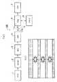
(撮像装置の全体構造)
この本発明の実施の形態となるビデオカメラ装置100は、図1に示すように被写体の撮像を行いCCDイメージセンサ1と、CCDイメージセンサ1からの撮像信号から相関二重サンプリング法を用いてノイズ成分を除去すると共に、これを適当な利得で増幅して出力するCDS/AGC2と、このCDS/AGC2からの出力をデジタル信号に変換するADC3と、このADC3からの撮像信号に対して所定のビデオプロセス処理等を施して出力するデジタルシグナルプロセッサ4(DSP)とを有している。
【0016】
また、このビデオカメラ装置100は、DSP4からの撮像信号を一旦記憶するメモリ6と、前記DSP4からの撮像信号をビデオテープに記録し再生するVTR7と、記録時にはDSP4からの撮像信号を選択して出力し、再生時にはVTR7により再生された撮像信号を選択して出力する切り替えスイッチ11と、メモリ6の記憶読み出し制御を行うメモリ制御部(FMC)5とを有している。
【0017】
さらに、このビデオカメラ装置100は、DSP4から供給される撮像信号に応じた画像及びVTR7で再生された画像を表示する、例えば電子ビューファインダや小型液晶モニタで形成された表示部8と、例えばテレビジョン受像器等の外部のモニタ装置に撮像信号を供給するための外部出力端子10と、撮像モードに応じて記録時にはCCDイメージセンサ1に蓄積された電荷の読み出し方を可変制御すると共に再生時には記録再生部7の再生状態を制御する制御部9とを有している。
【0018】
そして、CCDイメージセンサ1は、光電変換素子を多数格子状に配列してなる固体撮像部を有するものであり、各光電変換素子が受光によって蓄積した電荷を電気信号として出力するものである。なお、これの固体撮像部は、1フィールド期間内に各光電変換素子の読み出しを複数回行う。
【0019】
(記録時の動作)
次いで、上記構成を有するビデオカメラ装置100において画像を記録する動作について説明する。図2(a)は、図1に示した撮像装置100の記録時における動作を示すブロック図である。なお、ここではビデオカメラ装置100の3倍速モードで撮像する場合について説明する。
【0020】
先ず、制御部9は、通常の3倍の速さで各光電変換素子の電荷を読み出すように、1/180秒の間隔で、読み出し制御信号を各光電変換素子に供給する。これにより、光電変換素子に蓄積された電荷が、1/180秒の間隔で読み出されることとなる。
【0021】
CDS/AGC2は、CCDイメージセンサ1からの撮像信号が供給されると、この撮像信号にいわゆる相関二重サンプリング法に基づくノイズ除去処理を施してリセットノイズ等を除去し、これを適当な利得で増幅してADC3に供給する。このCDS/AGC2からの出力は、ADC3によってデジタル信号に変換される。
【0022】
DSP4は、補色系の色フィルタアレイにより得られた撮像信号に基づいて色分離(RGB)を行い、この撮像信号に対して所定のビデオプロセス処理等を施し、これを切り替えスイッチ11の被選択端子11bに供給する。この切り替えスイッチ11は、撮像時(記録時)には、選択端子11cにより被選択端子11bを選択するように切り替え制御されている。このため、DSP4からの撮像信号は、この切り替えスイッチ11を介して各フィールド毎にFMC5に供給される。
【0023】
FMC5は、この切り替えスイッチ11を介して供給された撮像信号をメモリ6に一旦記憶制御し、これを各フィールド毎に通常の記録レートで読み出してVTR7に供給する。これにより、VTR7において、所望の被写体の画像を各フィールド毎にビデオテープに記録することができる。
【0024】
VTR7では、1フレーム内に複数の画像を記録する。本実施形態では、1フィールド期間内に3回光電変換素子の電荷を読み出すため、VTR7では、図2(b)に示すように、1フィールド内に上下方向に3枚の画像が記録される。
【0025】
また、VTR7に画像を記録する際に、1フィールド期間内に何枚の画像が存在するかについての識別信号も併せて記録する。本実施形態では、1フィールド期間内に3枚の画像が存在するため、n=3として識別信号が記録される。さらに、本実施形態では、この識別信号には、1フィールド内に存在するn枚の画像がフィールド内においてどの位置にどのような順で記録されているかの表示位置に関する情報も含まれる。すなわち、本実施形態では、3枚の画像が、上から順に時系列に従って記録されているといった表示位置情報が、識別信号として記録される。
【0026】
なお、本実施形態においては、1フィールド内に3枚の画像を上下に分割して記録したが、本発明はこれに限定されるものではない。例えば、図3(a)に示すように、横方向に3枚の画像を並べるように存在させてもよい。また、本実施形態では、1フィールド内に3枚の画像を存在させたが、本発明はこれに限定されず、必要に応じて2枚、4枚、或いはそれ以上のn枚の画像を存在させることができる。この場合においても、例えば図3(b)〜(e)に示すように、上下或いは横方向に並べるようにして2、4……n枚の画像を存在させることができる。
【0027】
これらの場合、上述した識別信号には、例えば同図(a)にあっては「3枚の画像が横方向に時系列に従って配置されている。」という表示位置情報を含ませ、或いは同図(e)にあっては「4枚の画像が、1行目1列、1行目2列、2行目1列、2行目2列の順に時系列に従って配置されている」という表示位置情報を含ませる。
【0028】
(再生時の動作)
次に、このように記録された撮像信号の再生動作について説明する。図4(a)は、図1に示した撮像装置100の再生動作時におけるブロック図である。
【0029】
先ず、制御部9はVTR7を再生制御する。VTR7は、撮像信号を各フィールド毎にビデオテープから再生し、この再生信号を切り替えスイッチ11の被選択端子11aに供給する。なお、この再生信号を再生するとき、本実施形態では、撮像信号とともにスロー再生の際に使用される前記識別信号も再生される。
【0030】
切り替えスイッチ11は、再生時には、選択端子11cにより被選択端子11aを選択するように切り替え制御されている。このため、VTR7からの再生信号は、この切り替えスイッチ11及びFMC5を介して各フィールド毎に表示部8及び外部出力端子10に供給される。
【0031】
これにより、記録された画像を前記表示部8に表示することができ、また、外部出力端子10に例えばテレビジョン受像器等のモニタ装置が接続されている場合には、このモニタ装置に記録された画像を表示することができる。
【0032】
そして、ビデオテープに記録された画像をスローで再生する場合は、以下のように行われる。なお、本実施形態において、ビデオテープには、図2(b)に示したように、1フレーム内には3枚の画像が撮像画像として記録されている。
【0033】
先ず、この再生信号をVTR7によって読み出し再生し、順次メモリ6に一旦記憶させる。この再生信号の読み出しの際に、識別信号も読み出されている。
【0034】
次いで、この記憶された再生信号を、FMC5において識別信号に応じて時系列順に並べ替え、図4(b)に示すように、表示部8には、各画像が1フィールド期間に1枚ずつ表示されるようにする。このときの再生速度は、識別信号が有するn=3の値に基づいて、1/(n×m)となる。なお、このmの値は、操作者が任意の入力することができる。
【0035】
すなわち、本実施形態においては、識別信号によってnの値が定まり、操作者の選択によってmの値が定まり、これらの結果、スロー再生の速度が決定される。例えば、操作者がm=1と選択した場合には、1/3スローとなり、m=2と選択した場合には、1/6スローとなる。また、かかるFMC5での画像の並び替えは、識別信号に含まれる画像の表示位置情報に基づいて行われる。本実施形態においては、3枚の画像が1フィールド内に上から順に時系列に従って記録されていることから、FMC5では、メモリ6に記憶されたn枚の画像を、上から順に読み出し、表示部8に表示させる。
【0036】
かかる再生動作時のタイムチャートを図5に示す。なお、同図(a)は3倍速で録画したものを、操作者が「m=1」を選択することによって1/3スローで再生する場合について説明するものであり、(b)は、操作者が「m=2」を選択することによって1/6スローで再生する場合について説明するものである。
【0037】
同図に示すように、VTR(REC)では、垂直同期信号VDの信号間すなわち1フィールド期間内に3枚の画像を含む撮像信号が記録されている。具体的には、最初の1フィールドに「A,B,C」の画像が記録され、次のフィールドには「D,E,G」の画像が記録されている。
【0038】
そして、この撮像信号を再生する場合には、VTR(REC)に示すように、最初のフィールドにおいて、通常のレートで先ず上記A〜Cの画像を読み出す。これらの画像はメモリ6に記憶されるとともに、識別信号に基づいて、FMC5において並び替えられ、これら3枚の画像は(n×m)回、すなわち3回ずつ繰り返して再生モニター(表示手段8)に送出される。
【0039】
すなわち、本実施形態においてはnの値は3であり、操作者が「m=1」を選択していることから、1/(3×1)のスロー再生が行われることとなり、具体的には、同図(a)のVTR(PLAY)に示すように、「A,B,C」の3枚の画像を3フィールドにわたって3回繰り返して表示部8に送出する。
【0040】
そして、再生モニター(表示部8)では、第1フィールドにおいては「A」の画像のみを表示し、第2フィールドにおいては「B」の画像のみを表示し、第3フィールドにおいては「C」の画像のみを表示する。この結果、各画像が1フィールド毎に1枚ずつ、m回すなわち1回だけ表示される。
【0041】
一方、選択者がm=2を選択することによって1/6スローで再生する場合には、図5(b)に示すように、1フィールド期間に3枚存在する画像A〜CをVTRから読み出し、メモリ6に記憶するとともに、識別信号に基づいて、FMC5において並び替え、図中VTR(PLAY)に示すように、1フィールド期間毎に、(3×2)の回数、すなわち6回繰り返して再生モニターに送出する。
【0042】
そして、再生モニターでは、第1、2フィールドにおいては「A」の画像のみを表示し、第3、4フィールドにおいては「B」の画像のみを表示し、第5、6フィールドにおいては「C」の画像のみを表示する。この結果、各画像が1フィールド毎に1枚ずつ、m回すなわち2回繰り返して表示されることとなる。
【0043】
このようなビデオカメラ装置100のスロー再生によれば、1フィールド期間に複数枚存在する画像を時系列順に並べ替えて1フィールドごとに表示するものであるため、画像の動解像度が向上し、なめらかなスロー再生を実現することができる。また、このビデオカメラ装置100では、1フィールド期間内に何枚の画像が存在するかについての識別信号を、撮像信号とともに記録し、スロー再生のときには、この識別信号に基づいて適切な再生速度を決定するため、操作者は何倍速で記録されたものであるかの判断を要することなく、適切な速度でスロー再生を行うことができ、より容易にスロー再生を行うことができる。
【0044】
なお、本実施形態では、1フィールド期間に3枚の画像が上下に並んで存在する場合において、これらの画像のうちいずれか1枚を選択して表示させる形態について説明したが、本発明はこれに限定されるものではない。ビデオテープに記録された画像が、例えば図3(a)に示したような、横方向に並べて複数枚存在している場合に、これを表示するときには、例えば図6に示すように、いずれか1枚の画像を選択して表示するようにしてもよい。さらに、例えば図6(b)に示すように、画像の所要箇所を、電子ズーム等によって拡大して表示することもできる。
【0045】
【発明の効果】
以上説明した本発明の撮像装置によれば、1フィールド期間内にn枚の画像を記録し、これを再生する際には、1フィールド期間に1枚ずつ、m回繰り返して表示することによって1/(n×m)のスロー再生を行うので、ビデオカメラ装置におけるスロー再生の画像をスムーズなものとし、画質の向上を図ることができる。
【0046】
さらに、倍速撮像する際に1フィールド期間に何枚の画像が記録されているかについての識別信号をビデオテープ等に記録しておき、スロー再生のときにこの識別信号に基づいて再生速度を決定するとともに、記憶手段を制御するようにすれば、より容易にスロー再生を行うことができ、撮像装置の操作性の向上を図ることができる。
【図面の簡単な説明】
【図1】本発明に係る撮像装置を適用した実施の形態のビデオカメラ装置の全体構成を示すブロック図である。
【図2】(a)は、実施形態に係るビデオカメラ装置の記録時における動作を示すブロック図であり、(b)はその際に表示される画像の説明図である。
【図3】実施形態に係るビデオカメラ装置によって記録される画像の変形例を示す説明図である。
【図4】(a)は、実施形態に係るビデオカメラ装置の再生時における動作を示すブロック図であり、(b)はその際に表示される画像の説明図である。
【図5】実施形態に係るビデオカメラ装置の再生時における動作を示すタイムチャートである。
【図6】実施形態に係るビデオカメラ装置の再生時に表示される画像の変形例を示す説明図である。
【図7】従来のビデオカメラ装置の動作を示すブロック図である。
【符号の説明】
1…CCDイメージセンサ、6…メモリ、5…メモリ制御部(FMC)
2…相関二重サンプリング/自動利得制御部(CDS/AGC)
3…ADC、4…DSP、11…切り替えスイッチ
7…記録再生部(VTR)、8…表示部、9…制御部、10…外部出力端子[0001]
TECHNICAL FIELD OF THE INVENTION
The present invention relates to a CCD that captures an image of a subject using a solid-state imaging device, and an imaging device such as a video camera device and a camera device.
[0002]
[Prior art]
In today's video camera devices, a solid-state image pickup unit (CCD image sensor) formed of a plurality of solid-state image pickup devices is provided as an image pickup unit because it can be made smaller, lighter and lower in cost than an image pickup tube. FIG. 7A schematically shows a configuration of a conventional video camera device.
[0003]
A conventional
[0004]
The
[0005]
In the
[0006]
That is, the
[0007]
In order to reproduce the image recorded on the video tape in this manner, the output from the
[0008]
In particular, in the case of slow playback of an image recorded on a video tape in a conventional video camera apparatus, for example, in slow playback at a speed of 1/10, the first field recorded is played five times and the second field is played five times. The image of one frame is repeatedly reproduced in ten frame periods by reproducing the image one by one or repeating the image of one frame ten times.
[0009]
[Problems to be solved by the invention]
However, in the conventional video camera device, as described above, slow playback is performed by displaying one image in several field periods, so that image display during slow playback is intermittent and slow playback is performed. There is a problem that it is difficult to improve the dynamic resolution during reproduction.
[0010]
Therefore, the present invention has been made in view of the above-described problems, and has as its object to provide an imaging device capable of smoothing a slow reproduction image in a video camera device and improving the image quality.
[0011]
[Means for Solving the Problems]
In order to solve the above problem, an imaging apparatus according to thepresent invention includes an imaging apparatus including a display unit that reads out an electric charge accumulated by light reception by a photoelectric conversion element, records the electric charge as an imaging signal, reproduces the image, and displays the image as an image. Reading is performed n times within one field period, and n images are recorded as an imaging signal of one field,and information about the value of n and the display position is recorded as an identification signal together with theimaging signal. When reproducing the imaging signal, the imaging signal is temporarily stored in a storage unit, the identification signal is read out, thestorage unit is controlled in accordancewith the identification signal, and the n images are read. The images are rearranged in chronological order, and each image is repeatedly displayed one by one m in one field period, thereby performing 1 / (n × m) slow reproduction.
[0014]
BEST MODE FOR CARRYING OUT THE INVENTION
Hereinafter, a preferred embodiment of an imaging device according to the present invention will be described in detail with reference to the drawings. The imaging device according to the present invention can be applied to a video camera device.
[0015]
(Overall structure of imaging device)
As shown in FIG. 1, a
[0016]
Further, the
[0017]
Further, the
[0018]
The CCD image sensor 1 has a solid-state imaging unit in which a large number of photoelectric conversion elements are arranged in a grid, and outputs electric charges accumulated by each photoelectric conversion element by receiving light as electric signals. Note that the solid-state imaging unit performs reading of each photoelectric conversion element a plurality of times within one field period.
[0019]
(Operation during recording)
Next, an operation of recording an image in the
[0020]
First, the control unit 9 supplies a read control signal to each photoelectric conversion element at an interval of 1/180 second so that the charge of each photoelectric conversion element is read at three times the normal speed. As a result, the charges stored in the photoelectric conversion element are read at an interval of 1/180 second.
[0021]
When the imaging signal from the CCD image sensor 1 is supplied to the CDS /
[0022]
The DSP 4 performs color separation (RGB) based on the image signal obtained by the complementary color filter array, performs a predetermined video process process or the like on the image signal, and switches this to a selected terminal of the
[0023]
The
[0024]
The VTR 7 records a plurality of images in one frame. In this embodiment, since the charge of the photoelectric conversion element is read three times in one field period, the VTR 7 records three images in one field in the vertical direction as shown in FIG. 2B.
[0025]
When an image is recorded on the VTR 7, an identification signal indicating how many images exist in one field period is also recorded. In the present embodiment, since three images exist in one field period, the identification signal is recorded as n = 3. Further, in the present embodiment, the identification signal also includes information on a display position indicating in which position and in which order the n images present in one field are recorded in the field. That is, in the present embodiment, display position information indicating that three images are recorded in chronological order from the top is recorded as an identification signal.
[0026]
In the present embodiment, three images are vertically divided and recorded in one field, but the present invention is not limited to this. For example, as shown in FIG. 3A, three images may be arranged in the horizontal direction. Further, in the present embodiment, three images exist in one field, but the present invention is not limited to this, and two, four, or more n images exist as necessary. Can be done. Also in this case, for example, as shown in FIGS. 3B to 3E, 2, 4,..., N images can be arranged so as to be arranged vertically or horizontally.
[0027]
In these cases, the above-described identification signal includes, for example, display position information that “three images are arranged in a time series in the horizontal direction” in FIG. In (e), a display position "4 images are arranged in chronological order in the order of the first row and first column, the first row and second column, the second row and first column, and the second row and second column" Include information.
[0028]
(Operation during playback)
Next, the operation of reproducing the image signal thus recorded will be described. FIG. 4A is a block diagram at the time of the reproducing operation of the
[0029]
First, the control section 9 controls the reproduction of the VTR 7. The VTR 7 reproduces the image pickup signal from the video tape for each field, and supplies the reproduced signal to the selected terminal 11 a of the
[0030]
The
[0031]
As a result, the recorded image can be displayed on the
[0032]
When an image recorded on a video tape is reproduced at a slow speed, the following operation is performed. In this embodiment, as shown in FIG. 2B, three images are recorded as captured images in one frame on the video tape.
[0033]
First, the reproduced signal is read out and reproduced by the VTR 7 and is temporarily stored in the
[0034]
Next, the stored reproduction signals are rearranged in chronological order in the
[0035]
That is, in the present embodiment, the value of n is determined by the identification signal, and the value of m is determined by the selection of the operator. As a result, the speed of slow reproduction is determined. For example, when the operator selects m = 1, the speed is 1/3 slow, and when the operator selects m = 2, the speed is 1/6 slow. In addition, the rearrangement of the images in the
[0036]
FIG. 5 shows a time chart at the time of such a reproducing operation. FIG. 3A illustrates a case where a video recorded at 3 × speed is reproduced in 1/3 slow speed by selecting “m = 1” by the operator, and FIG. The case where the user selects "m = 2" to reproduce at 1/6 slow is described.
[0037]
As shown in the figure, in the VTR (REC), an image pickup signal including three images is recorded between signals of the vertical synchronization signal VD, that is, within one field period. Specifically, an image of “A, B, C” is recorded in the first field, and an image of “D, E, G” is recorded in the next field.
[0038]
When reproducing the image pickup signal, as shown in the VTR (REC), the images A to C are first read at a normal rate in the first field. These images are stored in the
[0039]
That is, in this embodiment, the value of n is 3, and since the operator has selected “m = 1”, 1 / (3 × 1) slow reproduction is performed. Sends three images "A, B, C" to the
[0040]
Then, on the reproduction monitor (display unit 8), only the image of "A" is displayed in the first field, only the image of "B" is displayed in the second field, and the image of "C" is displayed in the third field. Display only images. As a result, each image is displayed once per field, m times, that is, only once.
[0041]
On the other hand, when the selector selects m = 2 to reproduce at 1/6 slow, as shown in FIG. 5B, three images A to C existing in one field period are read from the VTR. Are stored in the
[0042]
Then, on the reproduction monitor, only the "A" image is displayed in the first and second fields, only the "B" image is displayed in the third and fourth fields, and "C" is displayed in the fifth and sixth fields. Display only images of. As a result, each image is displayed m times, that is, twice, one by one for each field.
[0043]
According to such a slow reproduction of the
[0044]
Note that, in the present embodiment, when three images are vertically arranged in one field period, one of these images is selected and displayed. However, the present invention is not limited to this. When there are a plurality of images recorded on a video tape arranged side by side as shown in FIG. 3A, for example, when displaying the images, as shown in FIG. One image may be selected and displayed. Further, for example, as shown in FIG. 6B, a required portion of the image can be enlarged and displayed by an electronic zoom or the like.
[0045]
【The invention's effect】
According to the imaging apparatus of the present invention described above, n images are recorded in one field period, and when these images are reproduced, one image is displayed repeatedly in one field period and displayed m times. Since the slow reproduction of / (n × m) is performed, the image of the slow reproduction in the video camera device can be made smooth and the image quality can be improved.
[0046]
Further, when performing double-speed imaging, an identification signal indicating how many images are recorded in one field period is recorded on a video tape or the like, and the playback speed is determined based on the identification signal during slow playback. At the same time, if the storage means is controlled, slow reproduction can be performed more easily, and operability of the imaging device can be improved.
[Brief description of the drawings]
FIG. 1 is a block diagram showing an overall configuration of a video camera device according to an embodiment to which an imaging device according to the present invention is applied.
FIG. 2A is a block diagram illustrating an operation of the video camera device according to the embodiment during recording, and FIG. 2B is an explanatory diagram of an image displayed at that time.
FIG. 3 is an explanatory diagram showing a modified example of an image recorded by the video camera device according to the embodiment.
FIG. 4A is a block diagram illustrating an operation of the video camera device according to the embodiment during reproduction, and FIG. 4B is an explanatory diagram of an image displayed at that time.
FIG. 5 is a time chart showing an operation at the time of reproduction of the video camera device according to the embodiment.
FIG. 6 is an explanatory diagram showing a modified example of an image displayed at the time of reproduction of the video camera device according to the embodiment.
FIG. 7 is a block diagram showing the operation of a conventional video camera device.
[Explanation of symbols]
1: CCD image sensor, 6: memory, 5: memory controller (FMC)
2: Correlated double sampling / automatic gain control unit (CDS / AGC)
3 ... ADC, 4 ... DSP, 11 ... Switch 7 ... Recording / reproducing unit (VTR), 8 ... Display unit, 9 ... Control unit, 10 ... External output terminal
Claims (1)
Translated fromJapanese前記読み出しを1フィールド期間内にn回行い、n枚の画像を1フィールドの撮像信号として記録するとともに、前記撮像信号とともに該nの値及び表示位置に関する情報を識別信号として記録しておき、
記録された前記撮像信号を再生する際には、該撮像信号を記憶手段に一時的に蓄積するとともに、前記識別信号を読み出し、該識別信号に応じて該記憶手段を制御し、該n枚の画像を時系列順に並べ替え、各画像を1フィールド期間に1枚ずつm回繰り返して表示することによって1/(n×m)のスロー再生を行うことを特徴とする撮像装置。In an image pickup apparatus including a display unit that reads out charges accumulated by light reception by the photoelectric conversion element and records the charges as an image pickup signal, reproduces the image, and displays the image as an image,
The reading is performed n times within one field period, and n images are recorded as an imaging signal of one field,and information on the value of n and the display position are recorded as an identification signal together with theimaging signal,
When reproducing the recorded image signal, the image signal is temporarily stored in a storage unit, the identification signal is read,and the storage unit is controlled in accordancewith the identification signal, and the nimage signals are read. An image pickup apparatus characterized in that 1 / (n × m) slow reproduction is performed by rearranging images in chronological order and repeatedly displaying each image m times in one field period.
Priority Applications (4)
| Application Number | Priority Date | Filing Date | Title |
|---|---|---|---|
| JP27385598AJP3596307B2 (en) | 1998-09-28 | 1998-09-28 | Imaging device |
| DE69932480TDE69932480T2 (en) | 1998-09-28 | 1999-09-24 | System and method for generating still images in slow playback mode |
| US09/406,267US6259857B1 (en) | 1998-09-28 | 1999-09-24 | Apparatus and method that provide smooth images in slow playback mode |
| EP99118077AEP0991274B1 (en) | 1998-09-28 | 1999-09-24 | Apparatus and method that provide smooth images in slow playback mode |
Applications Claiming Priority (1)
| Application Number | Priority Date | Filing Date | Title |
|---|---|---|---|
| JP27385598AJP3596307B2 (en) | 1998-09-28 | 1998-09-28 | Imaging device |
Publications (2)
| Publication Number | Publication Date |
|---|---|
| JP2000106642A JP2000106642A (en) | 2000-04-11 |
| JP3596307B2true JP3596307B2 (en) | 2004-12-02 |
Family
ID=17533502
Family Applications (1)
| Application Number | Title | Priority Date | Filing Date |
|---|---|---|---|
| JP27385598AExpired - LifetimeJP3596307B2 (en) | 1998-09-28 | 1998-09-28 | Imaging device |
Country Status (4)
| Country | Link |
|---|---|
| US (1) | US6259857B1 (en) |
| EP (1) | EP0991274B1 (en) |
| JP (1) | JP3596307B2 (en) |
| DE (1) | DE69932480T2 (en) |
Families Citing this family (10)
| Publication number | Priority date | Publication date | Assignee | Title |
|---|---|---|---|---|
| KR20000074616A (en)* | 1999-05-24 | 2000-12-15 | 윤종용 | Gain controller using switched capacitor |
| JP2002100113A (en)* | 2000-09-25 | 2002-04-05 | Canon Inc | Reproduction device, reproduction method, transmission device, transmission method, and storage medium |
| JPWO2003088659A1 (en)* | 2002-04-15 | 2005-08-25 | 松下電器産業株式会社 | Recording / playback device |
| US7006764B2 (en)* | 2002-11-12 | 2006-02-28 | Eastman Kodak Company | User interface for controlling cropping in electronic camera |
| US6907194B2 (en) | 2002-11-12 | 2005-06-14 | Eastman Kodak Company | Camera having continuously cropping viewfinder |
| US7561793B2 (en)* | 2002-11-12 | 2009-07-14 | Eastman Kodak Company | User interface for controlling cropping in electronic camera |
| JP4083139B2 (en)* | 2003-05-07 | 2008-04-30 | 三洋電機株式会社 | Analog-digital conversion circuit |
| KR100513387B1 (en) | 2003-07-25 | 2005-09-07 | 삼성전자주식회사 | Apparatus and method for amplifying analog signal and analog pre-processing circuits and image pick-up circuits |
| US8659619B2 (en) | 2004-03-26 | 2014-02-25 | Intellectual Ventures Fund 83 Llc | Display device and method for determining an area of importance in an original image |
| JP2006270868A (en)* | 2005-03-25 | 2006-10-05 | Olympus Imaging Corp | Imaging apparatus and image recording method |
Family Cites Families (6)
| Publication number | Priority date | Publication date | Assignee | Title |
|---|---|---|---|---|
| JPS5739676A (en)* | 1980-08-20 | 1982-03-04 | Sony Corp | Video recorder |
| KR970008606B1 (en)* | 1989-06-30 | 1997-05-27 | Lg Electronics Inc | Two head temporary slow circuit of vcr |
| JPH04304095A (en)* | 1991-03-31 | 1992-10-27 | Sony Corp | Picture signal converting device |
| JP3166247B2 (en)* | 1991-12-12 | 2001-05-14 | ソニー株式会社 | Video tape recorder |
| JP3604732B2 (en)* | 1994-07-01 | 2004-12-22 | キヤノン株式会社 | Video system |
| KR100251456B1 (en)* | 1997-11-04 | 2000-04-15 | 윤종용 | Screen device for low speed reproducing a moving picture |
- 1998
- 1998-09-28JPJP27385598Apatent/JP3596307B2/ennot_activeExpired - Lifetime
- 1999
- 1999-09-24EPEP99118077Apatent/EP0991274B1/ennot_activeExpired - Lifetime
- 1999-09-24USUS09/406,267patent/US6259857B1/ennot_activeExpired - Lifetime
- 1999-09-24DEDE69932480Tpatent/DE69932480T2/ennot_activeExpired - Lifetime
Also Published As
| Publication number | Publication date |
|---|---|
| JP2000106642A (en) | 2000-04-11 |
| DE69932480D1 (en) | 2006-09-07 |
| EP0991274B1 (en) | 2006-07-26 |
| EP0991274A2 (en) | 2000-04-05 |
| EP0991274A3 (en) | 2002-04-17 |
| US6259857B1 (en) | 2001-07-10 |
| DE69932480T2 (en) | 2007-03-01 |
Similar Documents
| Publication | Publication Date | Title |
|---|---|---|
| EP0465641B1 (en) | Record on command recording in a solid state fast frame recorder | |
| JP3740235B2 (en) | IMAGING DEVICE AND IMAGING RECORDING / REPRODUCING DEVICE | |
| JP3596307B2 (en) | Imaging device | |
| JP3824440B2 (en) | Imaging device | |
| JPH08275110A (en) | Digital image data recorder, its method and digital image data reproducing device and its method | |
| US20050089313A1 (en) | Recording and play reproducing device | |
| JPH0856323A (en) | Method and apparatus for video recording / recording / playback display | |
| JPH08154212A (en) | Method for generating still image data in video camera | |
| JPH08237561A (en) | Display device and recording / reproducing device | |
| JP2002252830A (en) | Image recording device | |
| JP4769589B2 (en) | Imaging apparatus and control method thereof | |
| JP3609870B2 (en) | Video camera and recording control method thereof | |
| JP3254211B2 (en) | Electronic still camera | |
| JP2010187112A (en) | Image reproducing device | |
| JP3674438B2 (en) | Captured image display system for solid-state imaging device | |
| EP0989746B1 (en) | Imaging apparatus having a high-speed imaging function with electronic zoom circuit | |
| JP2010187111A (en) | Image capturing apparatus | |
| JP4766318B2 (en) | Video processing apparatus and computer program | |
| JPH10108128A (en) | Digital electronic still camera | |
| JP3193557B2 (en) | Video signal recording and playback device | |
| JP3647102B2 (en) | Imaging device | |
| EP1069781A3 (en) | Video signal recording and/or reproducing apparatus and methods, and image pickup apparatus | |
| JP3193558B2 (en) | Video signal recording and playback device | |
| JPH11308535A (en) | Image pickup device | |
| JP2000106641A (en) | Imaging device |
Legal Events
| Date | Code | Title | Description |
|---|---|---|---|
| TRDD | Decision of grant or rejection written | ||
| A01 | Written decision to grant a patent or to grant a registration (utility model) | Free format text:JAPANESE INTERMEDIATE CODE: A01 Effective date:20040817 | |
| A61 | First payment of annual fees (during grant procedure) | Free format text:JAPANESE INTERMEDIATE CODE: A61 Effective date:20040830 | |
| FPAY | Renewal fee payment (event date is renewal date of database) | Free format text:PAYMENT UNTIL: 20080917 Year of fee payment:4 | |
| FPAY | Renewal fee payment (event date is renewal date of database) | Free format text:PAYMENT UNTIL: 20080917 Year of fee payment:4 | |
| FPAY | Renewal fee payment (event date is renewal date of database) | Free format text:PAYMENT UNTIL: 20090917 Year of fee payment:5 | |
| FPAY | Renewal fee payment (event date is renewal date of database) | Free format text:PAYMENT UNTIL: 20090917 Year of fee payment:5 | |
| FPAY | Renewal fee payment (event date is renewal date of database) | Free format text:PAYMENT UNTIL: 20100917 Year of fee payment:6 | |
| FPAY | Renewal fee payment (event date is renewal date of database) | Free format text:PAYMENT UNTIL: 20100917 Year of fee payment:6 | |
| FPAY | Renewal fee payment (event date is renewal date of database) | Free format text:PAYMENT UNTIL: 20110917 Year of fee payment:7 | |
| FPAY | Renewal fee payment (event date is renewal date of database) | Free format text:PAYMENT UNTIL: 20120917 Year of fee payment:8 | |
| FPAY | Renewal fee payment (event date is renewal date of database) | Free format text:PAYMENT UNTIL: 20120917 Year of fee payment:8 | |
| S111 | Request for change of ownership or part of ownership | Free format text:JAPANESE INTERMEDIATE CODE: R313111 | |
| FPAY | Renewal fee payment (event date is renewal date of database) | Free format text:PAYMENT UNTIL: 20120917 Year of fee payment:8 | |
| R350 | Written notification of registration of transfer | Free format text:JAPANESE INTERMEDIATE CODE: R350 | |
| FPAY | Renewal fee payment (event date is renewal date of database) | Free format text:PAYMENT UNTIL: 20120917 Year of fee payment:8 | |
| FPAY | Renewal fee payment (event date is renewal date of database) | Free format text:PAYMENT UNTIL: 20130917 Year of fee payment:9 | |
| EXPY | Cancellation because of completion of term |