JP3595800B2 - Protective shield - Google Patents
Protective shieldDownload PDFInfo
- Publication number
- JP3595800B2 JP3595800B2JP2002092737AJP2002092737AJP3595800B2JP 3595800 B2JP3595800 B2JP 3595800B2JP 2002092737 AJP2002092737 AJP 2002092737AJP 2002092737 AJP2002092737 AJP 2002092737AJP 3595800 B2JP3595800 B2JP 3595800B2
- Authority
- JP
- Japan
- Prior art keywords
- injector
- shield
- shield base
- handle
- mounting means
- Prior art date
- Legal status (The legal status is an assumption and is not a legal conclusion. Google has not performed a legal analysis and makes no representation as to the accuracy of the status listed.)
- Expired - Fee Related
Links
- 230000001681protective effectEffects0.000titleclaimsdescription70
- 238000002347injectionMethods0.000claimsdescription29
- 239000007924injectionSubstances0.000claimsdescription29
- 239000000203mixtureSubstances0.000claimsdescription22
- 239000000443aerosolSubstances0.000claimsdescription14
- 230000002940repellentEffects0.000claimsdescription13
- 239000005871repellentSubstances0.000claimsdescription13
- 239000003550markerSubstances0.000claimsdescription10
- 229920003002synthetic resinPolymers0.000claimsdescription9
- 239000000057synthetic resinSubstances0.000claimsdescription9
- 229920005668polycarbonate resinPolymers0.000claimsdescription7
- 239000004431polycarbonate resinSubstances0.000claimsdescription7
- 210000003813thumbAnatomy0.000claimsdescription6
- 238000003825pressingMethods0.000claimsdescription2
- 230000000694effectsEffects0.000description11
- 229910052751metalInorganic materials0.000description10
- 239000002184metalSubstances0.000description10
- 230000001846repelling effectEffects0.000description10
- 238000000034methodMethods0.000description8
- 239000007921spraySubstances0.000description8
- NMFHJNAPXOMSRX-PUPDPRJKSA-N[(1r)-3-(3,4-dimethoxyphenyl)-1-[3-(2-morpholin-4-ylethoxy)phenyl]propyl] (2s)-1-[(2s)-2-(3,4,5-trimethoxyphenyl)butanoyl]piperidine-2-carboxylateChemical compoundC([C@@H](OC(=O)[C@@H]1CCCCN1C(=O)[C@@H](CC)C=1C=C(OC)C(OC)=C(OC)C=1)C=1C=C(OCCN2CCOCC2)C=CC=1)CC1=CC=C(OC)C(OC)=C1NMFHJNAPXOMSRX-PUPDPRJKSA-N0.000description6
- ZOJBYZNEUISWFT-UHFFFAOYSA-Nallyl isothiocyanateChemical compoundC=CCN=C=SZOJBYZNEUISWFT-UHFFFAOYSA-N0.000description6
- 239000003380propellantSubstances0.000description6
- 238000003780insertionMethods0.000description5
- 230000037431insertionEffects0.000description5
- 229910000737DuraluminInorganic materials0.000description4
- 241000282414Homo sapiensSpecies0.000description4
- 210000004247handAnatomy0.000description4
- 239000000463materialSubstances0.000description4
- 235000016720allyl isothiocyanateNutrition0.000description3
- 210000003811fingerAnatomy0.000description3
- 239000007788liquidSubstances0.000description3
- 230000004048modificationEffects0.000description3
- 238000012986modificationMethods0.000description3
- 239000003973paintSubstances0.000description3
- 230000002093peripheral effectEffects0.000description3
- 230000002265preventionEffects0.000description3
- 239000000126substanceSubstances0.000description3
- 241000219198BrassicaSpecies0.000description2
- 235000003351Brassica creticaNutrition0.000description2
- 235000003343Brassica rupestrisNutrition0.000description2
- 241000282472Canis lupus familiarisSpecies0.000description2
- QKSKPIVNLNLAAV-UHFFFAOYSA-Nbis(2-chloroethyl) sulfideChemical compoundClCCSCCClQKSKPIVNLNLAAV-UHFFFAOYSA-N0.000description2
- 230000007123defenseEffects0.000description2
- 238000007599dischargingMethods0.000description2
- 230000005484gravityEffects0.000description2
- 239000002917insecticideSubstances0.000description2
- 235000010460mustardNutrition0.000description2
- IMACFCSSMIZSPP-UHFFFAOYSA-Nphenacyl chlorideChemical compoundClCC(=O)C1=CC=CC=C1IMACFCSSMIZSPP-UHFFFAOYSA-N0.000description2
- 210000004935right thumbAnatomy0.000description2
- 229910000838Al alloyInorganic materials0.000description1
- 241000282412HomoSpecies0.000description1
- 239000002390adhesive tapeSubstances0.000description1
- 230000015572biosynthetic processEffects0.000description1
- 230000037237body shapeEffects0.000description1
- 229940007061capsicum extractDrugs0.000description1
- 239000001943capsicum frutescens fruit extractSubstances0.000description1
- 239000011248coating agentSubstances0.000description1
- 238000000576coating methodMethods0.000description1
- 230000010485copingEffects0.000description1
- 230000000994depressogenic effectEffects0.000description1
- 238000004519manufacturing processMethods0.000description1
- 239000000049pigmentSubstances0.000description1
- 239000010970precious metalSubstances0.000description1
- 239000002904solventSubstances0.000description1
- 230000008685targetingEffects0.000description1
Images


Classifications
- F—MECHANICAL ENGINEERING; LIGHTING; HEATING; WEAPONS; BLASTING
- F41—WEAPONS
- F41H—ARMOUR; ARMOURED TURRETS; ARMOURED OR ARMED VEHICLES; MEANS OF ATTACK OR DEFENCE, e.g. CAMOUFLAGE, IN GENERAL
- F41H5/00—Armour; Armour plates
- F41H5/06—Shields
- F41H5/08—Shields for personal use, i.e. hand held shields
- F—MECHANICAL ENGINEERING; LIGHTING; HEATING; WEAPONS; BLASTING
- F41—WEAPONS
- F41H—ARMOUR; ARMOURED TURRETS; ARMOURED OR ARMED VEHICLES; MEANS OF ATTACK OR DEFENCE, e.g. CAMOUFLAGE, IN GENERAL
- F41H9/00—Equipment for attack or defence by spreading flame, gas or smoke or leurres; Chemical warfare equipment
- F41H9/10—Hand-held or body-worn self-defence devices using repellant gases or chemicals
Landscapes
- Engineering & Computer Science (AREA)
- General Engineering & Computer Science (AREA)
- Aiming, Guidance, Guns With A Light Source, Armor, Camouflage, And Targets (AREA)
Description
Translated fromJapanese【0001】
【発明の属する技術分野】
本発明は、強盗や暴漢等の外敵の攻撃から人体を防護する防護用盾に係り、特に外敵への対処をあまり訓練されていない使用者に好適な防護用盾に関する。
【0002】
【従来の技術】
従来、警護用・防護用盾としてはジュラルミン製の盾が用いられていた。
【0003】
さらに近年では、コンビニエンスストアや貴金属店、銀行、その他金融機関等を狙った強盗犯罪等が増加しており、いわゆる防犯グッズ等の防犯用具の需要が高まっている。
【0004】
このような防犯用具の例としては、カラシ抽出物等の刺激性組成物と噴射剤を封入したエアゾールが痴漢撃退用等の催涙スプレーとして用いられている。
【0005】
また、特開2001−315872号公報に記載の発明では、操作性を向上したエアゾール容器のレバー構造が提案されている。
【0006】
【発明が解決しようとする課題】
上述したように従来の警護用・防護用盾は、ジュラルミン製で重いため、訓練された警察官等の特定の人以外では上手く使用するのが困難であった。
【0007】
また、刃物を用いた暴漢等、近距離に存在する暴漢に対して撃退あるいは攻撃する従来の手段としては、催涙スプレー等の対人撃退用スプレーが発案されているが、咄嗟の際には、盾を片手に持ち、対人撃退用スプレーを同時にもう一方の手に持って対処するのは困難であった。特に、暴漢や強盗等の外敵への対処法をあまり訓練されていないコンビニエンスストアや銀行等の店員の場合は、防御の他に撃退や攻撃を加えようとして、片手に盾、もう一方の手に攻撃具を持つことができたとしても、攻撃具を持った手を暴漢に向けて露呈し攻撃するのには心理的に抵抗があった。
【0008】
本発明は、これらの事情に鑑みてなされたものであり、防護用盾全体が軽量であるとともに、盾基体部の内側面に噴射器を備えることができるようにして、強盗や暴漢等の外敵からの攻撃を防御しながら外敵に対して噴射器から威嚇、撃退、攻撃、逃亡追跡のうち少なくとも一つの効果が得られる物質を容易に噴射でき、暴漢や強盗などの外敵への対処法をあまり訓練されていないコンビニエンスストア、銀行等の店員等であっても、容易に扱うことが可能であり、防犯効果を高めることができる防護用盾を提供することを目的とする。
【0009】
【課題を解決するための手段】
前記目的を達成するため本願発明の防護用盾は、軽量高強度合成樹脂にて形成し、内側面と外側面とを有する盾基体部と、
この盾基体部の内側面側に設けた把手部と、
前記盾基体部の内側であって前記把手部に収納若しくは前記把手部の近傍に設けて、噴射器本体と噴射スイッチ又は噴射レバーとを備えた噴射器の噴射器本体側を固定するよう取り付ける噴射器取付手段と、
この噴射器取付手段により前記盾基体部の内側に固定されるエアゾール式の噴射器本体と、
前記噴射器本体側を前記噴射器取付手段により固定した状態で所定の操作により前記噴射器の噴射スイッチ又は噴射レバーを可動させて、充填された内容物を前記噴射器本体から吐出させることが可能な、前記把手部に位置する操作部と、
前記盾基体部の外側面に開口して形成され、前記噴射器取付手段にて取り付け固定される噴射器本体の吐出部に連通され、前記噴射器本体から吐出する内容物を前記盾基体部の内側面側から外部へ噴射させる吐出口と
を具備し、前記吐出口と前記噴射器本体の吐出部とを一直線上に配置したことを特徴とする。
また、本願発明の他の防護用盾は、噴射器本体を把手部の近傍に取り付ける防護用盾であって、
軽量高強度合成樹脂にて形成し、内側面と外側面とを有する盾基体部と、
この盾基体部の内側面側に設けた把手部と、
前記盾基体部の内側であって前記把手部との間に設けて、噴射器本体と噴射スイッチとを備えた噴射器の噴射器本体の底部を保持してこの噴射器本体を盾基体部側に固定する噴射器取付手段と、
この噴射器取付手段により前記盾基体部の内側に固定されたエアゾール式の噴射器本体と、
前記噴射器本体側を前記噴射器取付手段により盾基体部側に固定した状態で押し込み操作によって、前記噴射器の噴射スイッチを可動させて、充填された内容物を前記噴射器本体から吐出させるように、前記把手部を握ったとき手の親指を当接させ易い前記把手部の位置に配置した操作部と、
前記盾基体部の外側面に開口して形成され、前記噴射器取付手段に取り付け固定される噴射器本体の吐出部に連通され、前記噴射器本体から吐出する内容物を前記盾基体部の内側面側から外部へ噴射させる吐出口と
を具備し、前記吐出口と前記噴射器本体の吐出部とを一直線上に配置したことを特徴とする。
【0010】
請求項2に記載の防護用盾は、軽量高強度合成樹脂で形成し、内側面と外側面を有する盾基体部と、この盾基体部の内側面に設けた把手部と、前記盾基体部の内側に設けて、噴射器を取り付ける噴射器取付手段と、前記把手部に位置し、所定の操作により前記噴射器に充填された内容物を前記噴射器から吐出させることが可能な操作部と、前記盾基体部の外側面に開口して形成され、前記噴射器取付手段に取り付ける噴射器の吐出部に連通され、前記噴射器から吐出する内容物を前記盾基体部の内側面側から外部へ噴射させる吐出口と、を具備したことを特徴とする。
【0011】
請求項3に記載の防護用盾は、請求項1または2に記載の防護用盾であって、前記噴射器はエアゾールであることを特徴とする。
【0012】
請求項4に記載の防護用盾は、請求項1乃至3のいずれか一つに記載の防護用盾であって、前記噴射器に内蔵される内容物は、対人撃退組成物、マーキング剤の少なくとも一方を含有することを特徴とする。
【0013】
請求項5に記載の防護用盾は、請求項1乃至4のいずれか一つに記載の防護用盾であって、前記盾基体部はポリカーボネート樹脂により形成したことを特徴とする。
【0014】
請求項6に記載の防護用盾は、請求項1乃至5のいずれか一つに記載の防護用盾であって、前記盾基体部の内側面には、前記噴射器取付手段が複数取り付けられていることを特徴とする。
【0015】
請求項7に記載の防護用盾は、請求項1乃至6のいずれか一つに記載の防護用盾であって、前記盾基体部は、少なくとも噴射器の取り付け位置を半透明または不透明にするとともに、前記盾基体部の噴射器の取り付け位置より外側の少なくとも一部を透明にしたことを特徴とする。
【0016】
請求項8に記載の防護用盾は、請求項1乃至7のいずれか一つに記載の防護用盾であって、前記噴射器取付手段は前記把手部に内蔵されていることを特徴とする。
【0017】
請求項1、3乃至8に記載の防護用盾を使用する場合、まず、使用者は、前記盾基体部の内側面に設けられた前記把手部を把持して、前記防護用盾の外側面を強盗や暴漢等の外敵に対しに向けて、外敵の刃物等の攻撃から身を守るとともに、場合により前記噴射器の操作部を操作して前記噴射器の内容物を暴漢に向けて噴射する。
【0018】
請求項2乃至8に記載の防護用盾を使用する場合、まず、使用者は、前記盾基体部の内側面に設けられた前記把手部を把持して、前記防護用盾の外側面を強盗や暴漢等の外敵に対しに向けて、外敵の刃物等の攻撃から身を守るとともに、場合により前記把手部に設けられた操作部を操作して前記噴射器の内容物を暴漢に向けて噴射する。
【0019】
請求項1乃至8に記載の構成により、前記盾基体部を軽量高強度合成樹脂で形成したので、前記防護用盾の軽量化を図れるとともに、使用者は前記盾基体部の内側面に配置された操作部を操作することにより、前記噴射器に充填された内容物が前記吐出口を通して吐出するので、強盗や暴漢等の外敵に対して威嚇、撃退、攻撃、逃亡追跡のうち少なくとも一つの効果が得られる物質を容易に噴射できる。
【0020】
請求項7及び8に記載の構成により、強盗や暴漢等の外敵に対して噴射器を隠すことが可能で、前記噴射器に内容物を吐出させるまで、強盗や暴漢等の外敵を油断させることができる。
【0021】
本発明に用いられる噴射器に充填された内容物としては、対人撃退組成物であれば、クロルアセトフェノンやイソチオシアン酸アリル等の催涙組成物が用いられる。また、噴射器には、撃退用ではなく逃亡しそうになる暴漢に対してマーキング剤を噴射させてもてもよい。このマーキング剤としては、容易に剥離しない塗料または有臭組成物であれば特に制限はないが、蛍光あるいは夜光塗料が好ましい。また、マーキング剤としては、人間に検知できなくても警察犬等の犬に特に検知できる有臭組成物であっても良い。
【0022】
また、本発明に用いられる合成樹脂製の盾基体部は、軽量かつ高強度の材料が好ましく、特にジュラルミンに比べ軽量なポリカーボネート樹脂が好ましい。
【0023】
また、本発明に用いられる噴射器は、充填された内容物を吐出し強盗や暴漢等の外敵に対し噴射できるものであれば特に制限はなく、内容物をカプセル化した弾丸状物を発射あるいは投射できるようにしたり内容物を噴霧できるトリガーポンプ式噴霧器やエアゾールが用いられ、前記催涙組成物や対人撃退組成物、マーキング剤と噴射剤から成るエアゾール剤を用いたエアゾールが、簡便かつ操作性も容易のため好ましい。
【0024】
また、盾基体部に設けられた把手部近傍には、噴射器の吐出操作を行う操作部が設けられていることが好ましい。
【0025】
また、本発明に用いられる噴射器は、内容物を変えて、または変えずに複数用意して盾基体部内側面に取り付けておくことが好ましい。噴射器を内容物を変えて複数設ける場合において、例えば、暴漢撃退用の催涙スプレーと逃亡追跡用マーキング剤を封入したスプレーの2つを取り付けておけば、場面に応じて適切な内容物を噴射することができるため好ましい。また、複数の噴射器に同一の内容物を内蔵してもよく、この場合、噴射器の一つは予備として即座に噴射できるよう取り付けておけば、万一一つが故障しても予備の噴射器が機能して外的への攻撃が行えるため好ましい。
【0026】
【発明の実施の形態】
以下、本発明の実施の形態を図面を参照して説明する。
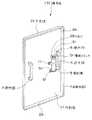
図1乃至図6は本発明の第1の実施の形態に係り、図1は防護用盾を示す斜視図、図2は図1の防護用盾の背面図、図3は図1の防護用盾の正面図、図4は防護用盾の右手用把手部を取り付けた部分の断面図、図5は防護用盾の噴射器を取り付けた部分の断面図、図6は噴射器及びその周辺部を示す斜視図である。
【0027】
図1及び図3に基づいて第1の実施の形態の全体構成を説明する。
図1に示すように、防護用盾1は、盾基体部2と、把手部3,4と、噴射器5と、吐出口23と、操作部6と、金具11,12を具備して構成されている。
盾基体部2は、軽量高強度合成樹脂で形成し、内側面21と外側面22とを有する。
【0028】
把手部3,4は、この盾基体部2の内側面21に設けられている。
噴射器5は、前記盾基体部2の内側面21に取り付けられている。
吐出口23は、前記盾基体部2の外側面に開口して形成され、前記噴射器5の吐き出し部(図5に示すノズル53)に連通され、前記噴射器5のノズル53から吐出する内容物を前記盾基体部2の外側面22側に噴射させる。
【0029】
操作部6は、前記盾基体部2の内側面21に設けられ、所定の操作により前記噴射器5に充填された内容物を前記吐出口23を通して吐出させることが可能になっている。
【0030】
金具11,12は、前記盾基体部2の内側に設けて、噴射器5を取り付ける噴射器取付手段となっている。
さらに詳細に説明すると、盾基体部2は、軽量高強度合成樹脂としてポリカーボネート樹脂を加工して形成している。盾基体部2の内側面21には、把手部として、左手用把手部3及び右手用把手部4を設けている。これにより、防護用盾1は、両手で把持することができるようになっている。
【0031】
内側面21の前記把手部4の近傍には、噴射器5を取り付けている。噴射器5には、内容物として対人撃退用組成物を内蔵したエアゾールを用いている。この噴射器5には噴射スイッチ51が設けられている。
【0032】
噴射器5は、金具11,12によって容器本体52が盾基体部2の内側面21にねじを外すことで取り外し可能な状態で取り付けられている。
把手部4を握った際に親指で操作できる位置には、操作部6を設けている。操作部6は、連動板61を介して噴射器5に設けられた噴射スイッチ51を連動して操作できる。
【0033】
前記盾基体部2の縁部には、湾曲部24が形成されている。
このような構造により、防護用盾1は、前記操作部6を押圧操作することで、噴射スイッチ51が連動して押し下げられ、噴射器5から対人撃退用組成物が吐出口23を通って外側面22側へ勢い良く噴射される。
【0034】
図2に示すように、盾基体部2は縦長の略長方形に形成されている。左手用把手部3と右手用把手部4は盾基体部2の同じ高さの位置にもうけられている。金具11は、帯状に形成されており、噴射器5の容器本体52を盾基体部2に押さえ付けている。金具12は、容器本体52の底部を下側から支えている。
【0035】
吐出口23は、盾基体部2の噴射スイッチ51に対応した位置に形成されている。連動板61は操作部6に連動して上下するようになっている。連動板61の下側には、噴射スイッチ51が配置している。
【0036】
図3に示すように、金具11は、外側面22から挿入された左右2つのねじ13によって、盾基体部2にねじ止め固定されている。金具12は、外側面22から挿入された左右2つのねじ14によって、盾基体部2にねじ止め固定されている。把手部3は、外側面22から挿入された上下2つのねじ15によって、盾基体部2にねじ止め固定されている。把手部4は、外側面22から挿入された上下2つのねじ16によって、盾基体部2にねじ止め固定されている。
【0037】
吐出口23からは、噴射器5の噴射スイッチ51に設けられたノズル53が露出している。
図4に示すように、盾基体部2は、上下2つのねじ16のねじ部が挿入され挿入孔25が形成されている。前記盾基体部2の湾曲部24は、内側面21に向けて円弧状に湾曲されて形成されている。
【0038】
図4乃至図6に示すように、操作部6は連動ピン62の一端側に取り付け固定されている。連動ピン62は、把手部4の上部に形成された貫通孔41に挿入されている。連動ピン62の他端側は、連動板61が取り付け固定されている。
【0039】
連動板61の下側には、噴射器5の噴射スイッチ51が配置し、噴射スイッチ51の下側に噴射器5の容器本体52が配置している。
前記盾基体部2に形成された吐出口23には、噴射スイッチ51に設けられたノズル53が挿入されており、このノズル53の噴射口から吐出口23を介して外側面22側へ対人撃退用組成物が噴射される。
【0040】
図5に示すように、金具12は、L字状に形成されており、容器本体52を下側から支えている。これにより、操作部6の押圧により連動板61が下げられ、噴射器5の噴射スイッチ51が下方に押圧された場合にも、容器本体52が金具11から下方に滑るのを防止している。
【0041】
図6に示すように、噴射器5の容器本体52の上面中央には噴射バルブ54が設けられており、噴射スイッチ51は、噴射バルブ54のステムに取り付けられている。噴射器5は、噴射スイッチ51を押すことで、噴射バルブ54が押し下げられ、容器本体52に内蔵した対人撃退用組成物が噴射バルブ54及びノズル53を介して噴射するようになっている。
【0042】
連動板61は、上面の一端側が連動ピン62に接続固定し、下面の他端側で噴射スイッチ51を押圧するようになっている。本実施の形態では、連動板61を適切な長さに形成することにより、把手部4と噴射器5の間に指を挿入できる隙間を設けている。
【0043】
次に、防護用盾1の使用方法を説明する。
使用者は、左右の手でそれぞれ左手用把手部3及び右手用把手部4を保持する。そして、防護用盾1の外側面22を強盗や暴漢等の外敵に向け、外敵の刃物等の攻撃から身を守る。次に、右手の親指を操作部6に当て、操作部6を押す。これにより、連動ピン62を介して連動板61が押し下げられ、噴射スイッチ51が押され、容器本体52に内蔵した対人撃退用組成物がノズル53を介して吐出口23から強盗や暴漢等の外敵に向けて噴射される。これにより、強盗や暴漢等の外敵を撃退できる。この場合、操作部6の操作は、防護用盾1の内側面21側で行えるので、操作を行う場合の心理的な抵抗が少ない。
【0044】
以上、説明したように本実施の形態によれば、軽量であるとともに、強盗や暴漢等の外敵に対して撃退の効果が得られる物質を容易に噴射できるので、暴漢や強盗等の外敵への対処法をあまり訓練されていないコンビニエンスストアや銀行等の店員の場合にも、容易に扱うことが可能になり、防犯効果を高めることが可能になる。
【0045】
ここで、盾基体部2の大きさは特に制限はないが、顔や少なくとも上半身が隠れるぐらいの大きさが好ましく、高さ25cm〜150cm×幅15cm〜90cm×厚さ0.lcm〜1cmが特に好ましい。なお、盾基体部2をポリカーボネート樹脂で製造した場合には、軽量かつ高強度であるため、厚みが2mm程度有れば刃物を貫通させない強度となり、5mm程度有れば銃弾を跳ね返す強度となるため、盾基体部2の厚さとしては、1.5mm〜5mm程度が特に好ましい。
【0046】
なお、ポリカーボネート樹脂の比重は約1.2であるから、ジュラルミン等のアルミ合金比重を2.75で算出すると、同程度の強度を有するものであっても、半分以下の重量で製造することができる。
【0047】
また、盾基体部2の形状としては特に制限はないが、円形、楕円形、正方形、長方形、野球のホームベース形、人体形状等が好ましく、取り扱い性の点で楕円形または長方形が特に好ましい。また、盾基体部2の形状が楕円あるいは長方形の場合には盾基体部2の中央より上方に平行して左手用把手部3、右手用把手部4を設けると、両手で強固に把持することができ、暴漢に対する防衛力が高まるため好ましい。
【0048】
なお、盾基体部2にポリカーボネート樹脂を用いれば、透明度の高い盾を製造することができ、視認性が良いため噴射器5から暴漢等に対人撃退用組成物を的確に噴射できる。
【0049】
また、噴射器5としては、暴漢を威嚇・撃退・攻撃するための内容物を、あるいは暴漢が逃亡しそうになった際に追跡するためのマーキング剤等の内容物を、暴漢に噴射できれば特に制限はなく、好ましくは液体の内容物を噴射できる噴射器が好ましい。特に好ましくは、前記液体の内容物と噴射剤とを内蔵したエアゾールが用いられる。また、エアゾールは、殺虫剤等に用いられる噴射力が強力なタイプが特に好ましく、対象物が3〜5m程度離れていても到達するものがよい。なお、エアゾールの噴射剤や噴射用バルブは殺虫剤等に用いられている既存のものが利用でき、内容物を1回の操作で全量噴射できるものが好ましく用いられる。
【0050】
噴射器5の内容物としては、対人撃退組成物を用いることができ、例えば、クロルアセトフェノン、イソチオシアン酸アリル、トウガラシ抽出物、マスタード抽出物等の種種のものが用いられる。第1の実施の形態では、イソチオシアン酸アリル0.2wt%、溶剤30wt%、噴射剤として高圧ガス69.8wt%を調製し、100mlの内容物を得た。この内容物を直径45mmφのエアゾール容器に封入し、図6に示す噴射バルブ54を取り付け、さらに操作しやすいように連動ピン62と連動板61による連動部を有する操作部6を設けた。このような材質による盾基体部2と噴射器5のこの重量は成人男性であれば片手で振り回すことこも容易であり、操作部が把手部にあるため操作しやすく、また、透明の盾となるため対象に対して噴射するのも容易であった。
【0051】
なお、内容物は、対人撃退組成物とマーキング剤の2種を混合して用いても良く、どちらか一方であっても良い。
また、噴射器5を盾基体部2の内側面21に固定して取り付ける噴射器取付手段としては特に制限はないが、噴射器固定用係止部を盾基体部2の内側面21の任意の位置に設けることにより固定するのが好ましい。さらに、この防護用盾を振り回しても容易に脱落しないように噴射器5を接着テープや面ファスナー等で固定するようにしても良い。
【0052】
図7は本発明の第2の実施の形態に係る防護用盾の右手用把手部を取り付けた部分の断面図である。第2の実施の形態において、図示以外の部分は第1の実施の形態と同様になっている。
【0053】
図7に示すように、第2の実施の形態の防護用盾101は、右手用把手部104に、噴射器105を内蔵している。
把手部104は、把手部本体141とカバー部142とから構成されている。カバー部142は把手部本体141に例えばねじ止めにより固定可能になっている。噴射器105は、把手部本体141とカバー部142の間に収納される。
【0054】
盾基体部102には、上下2つのねじ116のねじ部が挿入され挿入孔125が形成されている。把手部本体141は、外側面122から挿入された上下2つのねじ116によって、盾基体部102の内側面121にねじ止め固定されている。
【0055】
把手部104を握った際に親指で操作できる位置には、操作部106を設けている。操作部106は連動ピン162の一端側に取り付け固定されている。連動ピン162は、把手部本体141とカバー部142の間に形成される貫通孔143に挿入されている。連動ピン62の他端側は、脱落防止用のフランジ部161が形成され固定されている。フランジ部161の下側には、噴射器105の噴射スイッチ151が配置している。
【0056】
噴射器105の容器本体152は、把手部本体141とカバー部142の間に挟まれて固定されている。把手部本体141には、噴射器105のノズル153が挿入される貫通孔144が形成されている。吐出口123は、盾基体部102の貫通孔144に対応した位置に形成されている。噴射器105のノズル153の先端は、吐出口123に挿入される。
【0057】
このような構造により、前記把手部104は、前記噴射器105を取り付ける噴射器取付手段を内蔵している。
次に、防護用盾101の使用方法を説明する。
使用者は、左右の手で左手用把手部3(図1参照)及び右手用把手部104を保持する。次に、右手の親指を操作部106に当て、操作部106を押す。これにより、連動ピン162を介してフランジ部161が押し下げられ、噴射スイッチ151が押され、容器本体152に内蔵した対人撃退用組成物がノズル153を介して吐出口123から強盗や暴漢等の外敵に向けて噴射される。
【0058】
このような実施の形態によれば、第1の実施の形態と同様の効果が得られるとともに、噴射器105を右手用把手部104に収納できるので、強盗や暴漢等の外敵に対して噴射器105を隠すことが可能で、前記噴射器105に内容物を吐出させるまで、強盗や暴漢等の外敵を油断させることができる。
【0059】
尚、図7の第2の実施の形態では、右手用把手部104のみに噴射器105を収納したが、第2の実施の形態の変形例として、左手用把手部及びその周辺部を右手用把手部104側と同じ構造にして、左手用把手部にも噴射器も収納するように構成してもよい。
【0060】
この変形例において、右手用把手部104の噴射器105と左手用把手部の噴射器とで内容物を変えたとする。例えば、暴漢撃退用の催涙スプレーと逃亡追跡用マーキング剤を封入した噴射器の計2つを取り付けておけば、場面に応じて適切な内容物を噴射できる。
【0061】
また、この変形例において、右手用把手部104の噴射器105と左手用把手部の噴射器は、同一の内容物であっても良く、一つは予備として即座に噴射できるよう取り付けておけば、万一一つが故障しても予備の噴射器が機能して外敵に対して内容物を噴射できる。
【0062】
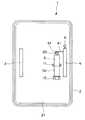
図8は本発明の第3の実施の形態に係る防護用盾の右手用把手部を取り付けた部分の断面図である。第3の実施の形態において、図示以外の部分は第1の実施の形態と同様になっている。
【0063】
図8において、第3の実施の形態の防護用盾201は、右手用の把手部204と盾基体部202の間に噴射器205を設け、噴射器205と右手用の把手部204とを直線的に配置している。
【0064】
把手部204は、外側面222から挿入孔225に挿入された上下2つのねじ216によって、盾基体部202の内側面221にねじ止め固定されている。
噴射器205は、金具211,212によって容器本体252が盾基体部202の内側面221に取り付けられている。
【0065】
把手部204を握った際に親指が当接する位置には、操作部206を設けている。操作部206は連動ピン262の一端側に取り付け固定されている。連動ピン262は、把手部204の上部に形成された貫通孔241に挿入されている。連動ピン262の他端側は、脱落防止用のフランジ部261が形成されている。フランジ部261の下側には、噴射器205の噴射レバー251が配置している。
【0066】
噴射器205は、噴射レバー251が押されることで、ノズル253から内容物を噴射するようになっている。噴射器205のノズル253の先端は、盾基体部202の吐出口223に挿入される。
【0067】
次に、防護用盾201の使用方法を説明する。
使用者は、右手の親指を操作部206に当て、操作部206を押す。これにより、連動ピン262を介してフランジ部261が押し下げられ、噴射レバー251が押され、容器本体252に内蔵した対人撃退用組成物がノズル253を介して吐出口223から強盗や暴漢等の外敵に向けて噴射される。
【0068】
このような第3の実施の形態によれば、第1の実施の形態と同様の効果が得られるとともに、噴射器205が右手の前側に配置されるため、操作者が対人撃退用組成物が噴射される方向を感覚的に理解しやすくなるという効果もある。
【0069】
図9は本発明の第4の実施の形態に係る防護用盾の右手用把手部を取り付けた部分の断面図である。第4の実施の形態において、図示以外の部分は第1の実施の形態と同様になっている。
【0070】
図9において、第4の実施の形態の防護用盾301は、盾基体部302の内側面321から外側面322に対し膨出部326を設けて、この膨出部326に噴射器305を収容するとともに、噴射器305と右手用把手部304とを直線的に配置している。
【0071】
盾基体部302は、膨出部326から上側及び下側の位置に、上下2つの挿入孔325が形成されている。把手部304は、外側面322から上下2つの挿入孔325に挿入された上下2つのねじ316によって、盾基体部302の内側面321にねじ止め固定されている。
【0072】
噴射器305は、金具311によって容器本体352が盾基体部302の内側面321に取り外し可能な状態で取り付けられている。
把手部304を握った際に人差し指に近接する位置には、噴射器305の噴射レバー351が配置している。噴射器305は、キャップ355に対して噴射レバー351が引かれることで、ノズル353から内容物を噴射するようになっている。
【0073】
噴射器305のノズル353の先端は、盾基体部302の吐出口323に挿入される。
次に、防護用盾301の使用方法を説明する。
使用者は、右手で把手部304を保持し、右手の人差し指を噴射レバー351の内側に当て、噴射レバー351を引く。これにより、容器本体352に内蔵した対人撃退用組成物がノズル353を介して吐出口323から強盗や暴漢等の外的に向けて噴射される。
【0074】
このような第4の実施の形態によれば、第3の実施の形態と同様の効果が得られるとともに、膨出部326の内側に噴射器305を固定したことで、噴射器305をより強固に固定でき、噴射器305の噴射レバー351を直接操作すればよいので、使用者に操作方法をより容易に理解させることができる。
【0075】
図10は本発明の第5の実施の形態に係る防護用盾の背面図である。
図10において、第5の実施の形態の防護用盾401は、盾基体部402と、左右両用の把手部4と、噴射器5と、吐出口423と、操作部6とから構成されている。
【0076】
左右両用の把手部4は、盾基体部402の左右を分割する中央の位置に設けられている。
噴射器5、金具11,12及び吐出口423は、盾基体部402の把手部4の左側の位置に設けられている。連動板61は操作部6に連動して上下するようになっている。連動板61の下側には、噴射スイッチ51が配置している。
【0077】
尚、前記盾基体部402は、噴射器5の取り付け位置より上側を透明となる透明部426とし、その下側を塗料等により不透明にした不透明部427としている。
【0078】
このような第5の実施の形態によれば、第1の実施の形態と同様の効果が得られるとともに、噴射器5を不透明部427の内側面421に設けているので、強盗や暴漢等の外敵に対して噴射器5を隠すことが可能で、前記噴射器5に内容物を吐き出させるまで、強盗や暴漢等の外敵を油断させることができる。
【0079】
尚、前記盾基体部402は、図10の構成に限らず、少なくとも噴射器5の取り付け位置を半透明または不透明にするとともに、前記盾基体部402の噴射器5の取り付け位置より外側の少なくとも一部を透明にすればよい。盾基体部402を半透明または不透明にする方法としては、塗装による方法以外に盾基体部の形成前の材質に顔料を混ぜる方法等がある。
【0080】
尚、第1、第3乃至第5の実施の形態では、前記盾基体部の内側面に、前記噴射器及び/または噴射器取付手段を一つだけ設けるように構成したが、前記噴射器及び/または噴射器取付手段を複数取り付け、これに合わせて吐出口や操作部を複数設けるようにしてもよい。また、防護用盾は、噴射器を別売にして販売するように構成してもよい。
【0081】
【発明の効果】
以上述べた様に本発明によれば、防護用盾全体が軽量であるとともに、盾基体部の内側面に噴射器を備えることができるため、強盗や暴漢等の外敵の攻撃を防御しながら外敵に対して噴射器から威嚇、撃退、攻撃、逃亡追跡のうち少なくとも一つの効果が得られる物質を容易に噴射できる。これにより暴漢や強盗等の外敵への対処法をあまり訓練されていないコンビニエンスストアや銀行等の店員の場合にも、容易に扱うことが可能になり、防犯効果を高めることが可能になる。
【図面の簡単な説明】
【図1】本発明の第1の実施の形態に係る防護用盾を示す斜視図。
【図2】図1の防護用盾の背面図。
【図3】図1の防護用盾の正面図
【図4】図1の防護用盾の右手用把手部を取り付けた部分の断面図。
【図5】図1の防護用盾の噴射器を取り付けた部分の断面図。
【図6】図1の噴射器及びその周辺部を示す斜視図。
【図7】本発明の第2の実施の形態に係る防護用盾の右手用把手部を取り付けた部分の断面図。
【図8】本発明の第3の実施の形態に係る防護用盾の右手用把手部を取り付けた部分の断面図。
【図9】本発明の第4の実施の形態に係る防護用盾の右手用把手部を取り付けた部分の断面図。
【図10】本発明の第5の実施の形態に係る防護用盾の斜視図。
【符号の説明】
1 …防護用盾
2 …盾基体部
3,4 …把手部
5 …噴射器
6 …操作部
21 …内側面
22 …外側面
23 …吐出口
51 …噴射スイッチ[0001]
TECHNICAL FIELD OF THE INVENTION
BACKGROUND OF THE
[0002]
[Prior art]
Conventionally, duralumin shields have been used as guard / protective shields.
[0003]
Furthermore, in recent years, there has been an increase in robbery crimes targeting convenience stores, precious metal stores, banks, other financial institutions, and the like, and demand for security equipment such as so-called security goods has been increasing.
[0004]
As an example of such a security device, an aerosol containing an irritating composition such as mustard extract and a propellant has been used as a tear spray for repelling molesters.
[0005]
Further, in the invention described in JP-A-2001-315872, a lever structure of an aerosol container with improved operability is proposed.
[0006]
[Problems to be solved by the invention]
As described above, the conventional guard / protective shield is made of duralumin and is heavy, so that it has been difficult to use it effectively except for trained police officers and other specific persons.
[0007]
As a conventional means of repelling or attacking a thug at a short distance, such as a thug using a knife, an anti-personnel spray such as a tear spray is proposed. It was difficult to handle in one hand with the anti-personnel spray at the same time in the other hand. In particular, in the case of a clerk at a convenience store or a bank, etc., who is not well trained in how to deal with external enemies such as thugs and robbers, shield in one hand and try to attack and attack in addition to defense. Even if they could do so, they were psychologically resistant to revealing and attacking the hand with the attacker at the thug.
[0008]
The present invention has been made in view of these circumstances. The entire protective shield is lightweight, and an injector can be provided on the inner surface of the shield base, so that an enemy such as a robber or a thief can be provided. It can easily eject a substance that can at least one of threat, repulsion, attack, and escape tracking against the enemy from the injector while defending attacks from the enemy, and there is not much way to deal with external enemies such as thugs and robbers It is an object of the present invention to provide a protective shield that can be easily handled even by an untrained convenience store, a clerk of a bank or the like, and can enhance the crime prevention effect.
[0009]
[Means for Solving the Problems]
To achieve the above object, the protective shield of the present invention is formed of a lightweight high-strength synthetic resin, a shield base having an inner surface and an outer surface,
A handle provided on the inner surface side of the shield base,
Inside the shield baseAnd stored in the handle or in the vicinity of the handle Provided inOf an injector with an injector body and an injection switch or injection lever InjectorSo that the body side is fixed Injector mounting means for mounting;
It is fixed to the inside of the shield base by this injector mounting means.Aerosol type InjectorBody When,
With the injector body side fixed by the injector mounting means By a predetermined operationBy moving the injection switch or injection lever of the injector, An operation unit located on the handle, which allows the filled content to be discharged from the injector body,
An opening is formed on the outer surface of the shield base portion, and attached by the injector attaching means.Fixed A discharge port which is communicated with a discharge portion of the injector main body, and discharges contents discharged from the injector main body to the outside from the inner surface side of the shield base portion;
Wherein the discharge port and the discharge portion of the injector main body are arranged on a straight line.
Another protective shield according to the present invention is a protective shield for mounting the injector body near the handle,
A shield base portion formed of a lightweight high-strength synthetic resin and having an inner surface and an outer surface,
A handle provided on the inner surface side of the shield base,
Inside the shield base portion,The injector body is provided between the handle portion and the bottom portion of the injector body of the injector having the injector body and the injection switch, and the injector body is fixed to the shield base portion side. Injector mounting means;
It was fixed inside the shield base part by this injector mounting means.Aerosol type InjectorBody When,
By pushing in with the injector body side fixed to the shield base part side by the injector mounting means, Operate the injection switch of the injector to discharge the filled contents from the injector bodyAs described above, the handle is disposed at the position of the handle where the thumb of the hand is easily brought into contact when the handle is gripped. An operation unit,
An opening is formed on the outer surface of the shield base, and the shield base is attached to the injector mounting means.Fixed A discharge port which is communicated with a discharge portion of the injector main body, and discharges contents discharged from the injector main body to the outside from the inner surface side of the shield base portion;
Wherein the discharge port and the discharge portion of the injector main body are arranged on a straight line.
[0010]
3. The protective shield according to
[0011]
The protective shield according to
[0012]
The protective shield according to
[0013]
A protective shield according to a fifth aspect is the protective shield according to any one of the first to fourth aspects, wherein the shield base is formed of a polycarbonate resin.
[0014]
The protective shield according to
[0015]
The protective shield according to claim 7 is the protective shield according to any one of
[0016]
The protective shield according to claim 8 is the protective shield according to any one of
[0017]
When using the protective shield according to
[0018]
When using the protective shield according to
[0019]
According to the configuration of
[0020]
According to the configuration of claims 7 and 8, it is possible to hide the injector from external enemies such as robbers and thugs, and to keep off guard against external enemies such as robbers and thugs until the injector ejects the contents. Can be.
[0021]
As the contents filled in the injector used in the present invention, a tearing composition such as chloroacetophenone or allyl isothiocyanate is used as long as it is a composition for repelling human beings. Further, the injector may be made to inject a marking agent against a thug who is about to escape instead of repelling. The marking agent is not particularly limited as long as it is a paint or an odorous composition that does not easily peel off, but a fluorescent or luminous paint is preferred. In addition, the marking agent may be an odorous composition that cannot be detected by humans but can be detected particularly by dogs such as police dogs.
[0022]
The shield base made of synthetic resin used in the present invention is preferably made of a lightweight and high-strength material, particularly preferably a polycarbonate resin which is lighter than duralumin.
[0023]
In addition, the injector used in the present invention is not particularly limited as long as it can discharge the filled content and inject it against an enemy such as a burglar or a thug, and can fire a bullet-shaped material encapsulating the content or A trigger pump sprayer or an aerosol that can be projected or sprayed the contents is used, and the tearing composition or the anti-personnel repellent composition, an aerosol using an aerosol composed of a marking agent and a propellant, is simple and easy to operate. Preferred for ease.
[0024]
In addition, it is preferable that an operation unit for performing an ejection operation of the injector is provided in the vicinity of a handle provided on the shield base.
[0025]
In addition, it is preferable that a plurality of injectors used in the present invention be prepared with or without changing the content and attached to the inner surface of the shield base. In the case where a plurality of injectors are provided with different contents, for example, by installing two sprays, a tear spray for repelling a thug and a spray containing a marking agent for escape tracking, appropriate contents are ejected according to the scene. Is preferred. In addition, the same contents may be incorporated in a plurality of injectors. In this case, if one of the injectors is mounted so that it can be immediately injected as a spare, the spare injection can be performed even if one of the injectors fails. This is preferable because the vessel functions and can perform an external attack.
[0026]
BEST MODE FOR CARRYING OUT THE INVENTION
Hereinafter, embodiments of the present invention will be described with reference to the drawings.
1 to 6 relate to a first embodiment of the present invention. FIG. 1 is a perspective view showing a protective shield, FIG. 2 is a rear view of the protective shield of FIG. 1, and FIG. 3 is a protective shield of FIG. Front view of the shield, FIG. 4 is a cross-sectional view of a portion of the protective shield to which a right hand handle is attached, FIG. 5 is a cross-sectional view of a portion of the protective shield to which an injector is attached, and FIG. 6 is an injector and its peripheral portion. FIG.
[0027]
The overall configuration of the first embodiment will be described with reference to FIGS.
As shown in FIG. 1, the
The
[0028]
The
The
The
[0029]
The
[0030]
The
More specifically, the
[0031]
An
[0032]
The
An
[0033]
A
With this structure, the
[0034]
As shown in FIG. 2, the
[0035]
The
[0036]
As shown in FIG. 3, the
[0037]
A
As shown in FIG. 4, the
[0038]
As shown in FIGS. 4 to 6, the
[0039]
The injection switch 51 of the
A
[0040]
As shown in FIG. 5, the
[0041]
As shown in FIG. 6, an
[0042]
One end of the upper surface of the interlocking
[0043]
Next, a method of using the
The user holds the
[0044]
As described above, according to the present embodiment, while being lightweight, it is possible to easily eject a substance capable of obtaining a repelling effect on external enemies such as robbers and burglars. In the case of a clerk at a convenience store or a bank where the coping method is not so well-trained, it is possible to easily handle the clerk and enhance the crime prevention effect.
[0045]
Here, the size of the
[0046]
Since the specific gravity of the polycarbonate resin is about 1.2, if the specific gravity of an aluminum alloy such as duralumin is calculated to be 2.75, it can be manufactured with less than half the weight even if it has the same strength. it can.
[0047]
The shape of the
[0048]
If a polycarbonate resin is used for the
[0049]
In addition, the
[0050]
As the contents of the
[0051]
The content may be a mixture of two or more of an anti-personnel repellent composition and a marking agent, or either one of them may be used.
The injector mounting means for fixing the
[0052]
FIG. 7 is a cross-sectional view of a portion of the protective shield according to the second embodiment of the present invention to which a handle for a right hand is attached. In the second embodiment, parts other than those shown are the same as those in the first embodiment.
[0053]
As shown in FIG. 7, a protective shield 101 according to the second embodiment has an injector 105 built in a right-hand handle 104.
The handle 104 includes a handle main body 141 and a cover 142. The cover part 142 can be fixed to the handle part body 141 by, for example, screwing. The injector 105 is housed between the handle body 141 and the cover 142.
[0054]
In the shield base portion 102, an insertion hole 125 is formed by inserting a screw portion of two upper and lower screws 116. The handle body 141 is screwed and fixed to the inner surface 121 of the shield base 102 by two upper and lower screws 116 inserted from the outer surface 122.
[0055]
An operation unit 106 is provided at a position where the thumb can be operated when the grip unit 104 is gripped. The operation unit 106 is attached and fixed to one end of the interlocking pin 162. The interlocking pin 162 is inserted into a through hole 143 formed between the handle main body 141 and the cover 142. The other end of the interlocking
[0056]
The container main body 152 of the injector 105 is fixed between the handle main body 141 and the cover 142. The handle body 141 has a through hole 144 into which the nozzle 153 of the injector 105 is inserted. The discharge port 123 is formed at a position corresponding to the through hole 144 of the shield base 102. The tip of the nozzle 153 of the injector 105 is inserted into the discharge port 123.
[0057]
With such a structure, the handle portion 104 incorporates injector mounting means for mounting the injector 105.
Next, a method of using the protective shield 101 will be described.
The user holds the left hand handle 3 (see FIG. 1) and the right hand handle 104 with left and right hands. Next, the right thumb is applied to the operation unit 106 and the operation unit 106 is pressed. As a result, the flange portion 161 is pushed down via the interlocking pin 162, the ejection switch 151 is pushed, and the anti-personnel repellent composition contained in the container main body 152 is discharged from the discharge port 123 via the nozzle 153 to a foreign enemy such as a burglar or a thug. Injected toward.
[0058]
According to such an embodiment, the same effect as that of the first embodiment can be obtained, and the injector 105 can be stored in the right-hand handle 104. 105 can be hidden, and it is possible to keep off guard against external enemies such as robbers and thugs until the injector 105 discharges the contents.
[0059]
In the second embodiment shown in FIG. 7, the injector 105 is housed only in the right-hand handle 104. However, as a modification of the second embodiment, the left-hand handle and its peripheral portion are used for the right hand. The structure may be the same as that of the handle portion 104, and the injector may also be housed in the left hand handle portion.
[0060]
In this modification, it is assumed that the contents are changed between the injector 105 of the right-hand handle 104 and the injector of the left-hand handle. For example, if a total of two tear sprays for repelling thugs and an injector containing a marking agent for escape tracking are attached, appropriate contents can be injected according to the scene.
[0061]
In this modification, the injector 105 of the right-hand handle 104 and the injector of the left-hand handle may have the same contents, and one may be provided as a spare so that it can be immediately ejected. In the unlikely event that a failure occurs, the spare injector can function to eject the contents to a foreign enemy.
[0062]
FIG. 8 is a cross-sectional view of a portion of a protective shield according to a third embodiment of the present invention, to which a right-hand handle is attached. In the third embodiment, portions other than those shown are the same as those in the first embodiment.
[0063]
8, a
[0064]
The
In the
[0065]
An
[0066]
The
[0067]
Next, a method of using the
The user puts the right thumb on the
[0068]
According to such a third embodiment, the same effect as in the first embodiment can be obtained, and since the
[0069]
FIG. 9 is a sectional view of a part of a protective shield according to a fourth embodiment of the present invention, to which a right-hand handle is attached. In the fourth embodiment, parts other than those shown are the same as those in the first embodiment.
[0070]
In FIG. 9, the
[0071]
The
[0072]
In the
The
[0073]
The tip of the
Next, a method of using the
The user holds the
[0074]
According to such a fourth embodiment, the same effect as in the third embodiment can be obtained, and the
[0075]
FIG. 10 is a rear view of the protective shield according to the fifth embodiment of the present invention.
In FIG. 10, a
[0076]
The left and
The
[0077]
The
[0078]
According to such a fifth embodiment, the same effects as those of the first embodiment can be obtained, and the
[0079]
The
[0080]
In the first, third to fifth embodiments, only one injector and / or injector mounting means is provided on the inner surface of the shield base portion. A plurality of injector mounting means may be mounted, and a plurality of discharge ports and operation units may be provided in accordance with the mounting. Further, the protective shield may be configured so that the injector is sold separately.
[0081]
【The invention's effect】
As described above, according to the present invention, since the entire protective shield is lightweight and the injector can be provided on the inner surface of the shield base, the external shield can be protected from attacks by external enemies such as robbers and thugs. In contrast, the injector can easily eject a substance that provides at least one of the effects of threat, repulsion, attack, and escape tracking. As a result, even a clerk at a convenience store or a bank, etc., who is not well trained in how to deal with external enemies such as thugs and robbery, can be easily handled, and the crime prevention effect can be enhanced.
[Brief description of the drawings]
FIG. 1 is a perspective view showing a protective shield according to a first embodiment of the present invention.
FIG. 2 is a rear view of the protective shield shown in FIG. 1;
FIG. 3 is a front view of the protective shield of FIG. 1;
FIG. 4 is a cross-sectional view of a portion of the protective shield of FIG. 1 to which a handle for a right hand is attached.
FIG. 5 is a sectional view of a portion of the protective shield of FIG. 1 to which an injector is attached.
FIG. 6 is a perspective view showing the injector of FIG. 1 and a peripheral portion thereof.
FIG. 7 is a cross-sectional view of a portion of a protective shield according to a second embodiment of the present invention to which a right-hand handle is attached.
FIG. 8 is a cross-sectional view of a part of a protective shield according to a third embodiment of the present invention, to which a handle for a right hand is attached.
FIG. 9 is a cross-sectional view of a part of a protective shield according to a fourth embodiment of the present invention, to which a handle for a right hand is attached.
FIG. 10 is a perspective view of a protective shield according to a fifth embodiment of the present invention.
[Explanation of symbols]
1. Protective shield
2. Shield base
3,4… handle
5 ... injector
6 Operation unit
21 ... Inner surface
22 ... outer surface
23… Discharge port
51 ... injection switch
Claims (6)
Translated fromJapaneseこの盾基体部の内側面側に設けた把手部と、
前記盾基体部の内側であって前記把手部に収納若しくは前記把手部の近傍に設けて、噴射器本体と噴射スイッチ又は噴射レバーとを備えた噴射器の噴射器本体側を固定するよう取り付ける噴射器取付手段と、
この噴射器取付手段により前記盾基体部の内側に固定されるエアゾール式の噴射器本体と、
前記噴射器本体側を前記噴射器取付手段により固定した状態で所定の操作により前記噴射器の噴射スイッチ又は噴射レバーを可動させて、充填された内容物を前記噴射器本体から吐出させることが可能な、前記把手部に位置する操作部と、
前記盾基体部の外側面に開口して形成され、前記噴射器取付手段にて取り付け固定される噴射器本体の吐出部に連通され、前記噴射器本体から吐出する内容物を前記盾基体部の内側面側から外部へ噴射させる吐出口と
を具備し、前記吐出口と前記噴射器本体の吐出部とを一直線上に配置したことを特徴とする防護用盾。A shield base portion formed of a lightweight high-strength synthetic resin and having an inner surface and an outer surface,
A handle provided on the inner surface side of the shield base,
Injection mounted inside the shield base portion and provided in thehandle portion or in the vicinity of thehandle portionto fixthe injectorbody side ofthe injector having theinjector body and the ejection switch or ejection leverso as to be fixed. Container mounting means,
Anaerosol type injectormain body fixed inside the shield base portion by the injector mounting means,
With the injector main body side fixed by the injector mounting means, the injection switch or the injection lever of the injector can be moved by a predetermined operation to dischargethe filled contents from the injector main body. An operation unit located on the handle unit;
Is formed open to the outer surface of the shield body portion, communicates with a discharge portion of the injector body thatwill be mountedfixed at the injector mounting means, the contents to be discharged from the injector body of the shield base portion A protective shield, comprising: a discharge port for ejecting from an inner surface side to the outside, wherein the discharge port and a discharge section of the injector main body are arranged in a straight line.
軽量高強度合成樹脂にて形成し、内側面と外側面とを有する盾基体部と、
この盾基体部の内側面側に設けた把手部と、
前記盾基体部の内側であって前記把手部との間に設けて、噴射器本体と噴射スイッチとを備えた噴射器の噴射器本体の底部を保持してこの噴射器本体を盾基体部側に固定する噴射器取付手段と、
この噴射器取付手段により前記盾基体部の内側に固定されたエアゾール式の噴射器本体と、
前記噴射器本体側を前記噴射器取付手段により盾基体部側に固定した状態で押し込み操作によって、前記噴射器の噴射スイッチを可動させて、充填された内容物を前記噴射器本体から吐出させるように、前記把手部を握ったとき手の親指を当接させ易い前記把手部の位置に配置した操作部と、
前記盾基体部の外側面に開口して形成され、前記噴射器取付手段に取り付け固定される噴射器本体の吐出部に連通され、前記噴射器本体から吐出する内容物を前記盾基体部の内側面側から外部へ噴射させる吐出口と
を具備し、前記吐出口と前記噴射器本体の吐出部とを一直線上に配置したことを特徴とする防護用盾。A protective shield for mounting the injector body near the handle,
A shield base portion formed of a lightweight high-strength synthetic resin and having an inner surface and an outer surface,
A handle provided on the inner surface side of the shield base,
Provided inside the shield baseand between the handle, holding the bottom of the injector body of the injector having the injector body and the injection switch, and holding the injector body on the shield base side Injector mounting meansfixed to the
Anaerosol-type injectorbody fixed inside the shield base portion by the injector mounting means,
By the pressing operation in a state of fixing the shield body portion side by the injector mounting means said injector body, said by moving the injection switch of the injector,so as to eject the filled contents from the injector bodyAn operation unitdisposed at a position of the handle portion where a thumb of a hand is easily brought into contact when gripping the handle portion ;
The shield base portion are formed open to the outer surface of, in communication with the discharge portion of the injector injector body thatwill be fixedly attached to the mounting means, among the contents to be discharged from the injector body of the shield base portion A protective shield, comprising: a discharge port for ejecting from a side surface to the outside; wherein the discharge port and a discharge portion of the injector main body are arranged in a straight line.
Priority Applications (1)
| Application Number | Priority Date | Filing Date | Title |
|---|---|---|---|
| JP2002092737AJP3595800B2 (en) | 2002-03-28 | 2002-03-28 | Protective shield |
Applications Claiming Priority (1)
| Application Number | Priority Date | Filing Date | Title |
|---|---|---|---|
| JP2002092737AJP3595800B2 (en) | 2002-03-28 | 2002-03-28 | Protective shield |
Publications (2)
| Publication Number | Publication Date |
|---|---|
| JP2003287398A JP2003287398A (en) | 2003-10-10 |
| JP3595800B2true JP3595800B2 (en) | 2004-12-02 |
Family
ID=29237479
Family Applications (1)
| Application Number | Title | Priority Date | Filing Date |
|---|---|---|---|
| JP2002092737AExpired - Fee RelatedJP3595800B2 (en) | 2002-03-28 | 2002-03-28 | Protective shield |
Country Status (1)
| Country | Link |
|---|---|
| JP (1) | JP3595800B2 (en) |
Families Citing this family (8)
| Publication number | Priority date | Publication date | Assignee | Title |
|---|---|---|---|---|
| JP3535501B2 (en) | 2002-08-19 | 2004-06-07 | 株式会社レニアス | Tear spray shield |
| JP2006207898A (en)* | 2005-01-26 | 2006-08-10 | Renias:Kk | Shield for self-defence |
| JP2007010295A (en)* | 2005-07-04 | 2007-01-18 | Renias:Kk | Protection shield |
| JP2007071441A (en)* | 2005-09-06 | 2007-03-22 | Renias:Kk | Gas jet device for defensive shield |
| USD563502S1 (en)* | 2006-05-12 | 2008-03-04 | Tota Dra Hacek Over Zen | Decorative shield |
| CN103335562A (en)* | 2013-07-25 | 2013-10-02 | 李先强 | Military shield charge |
| CN107894190A (en)* | 2017-12-13 | 2018-04-10 | 河南中泰警用装备科技有限公司 | The police riot shield of Multifunctional strong-light |
| JP2023080990A (en)* | 2021-11-30 | 2023-06-09 | 田村装備開発株式会社 | Control shield, control rod and combination thereof |
- 2002
- 2002-03-28JPJP2002092737Apatent/JP3595800B2/ennot_activeExpired - Fee Related
Also Published As
| Publication number | Publication date |
|---|---|
| JP2003287398A (en) | 2003-10-10 |
Similar Documents
| Publication | Publication Date | Title |
|---|---|---|
| US5517180A (en) | Personal protection device | |
| US4135645A (en) | Self-defense ring | |
| US7787232B2 (en) | Multifunction security device | |
| JP3595800B2 (en) | Protective shield | |
| US5644297A (en) | Personal protection device | |
| US20120118990A1 (en) | Personal defense spray gun and method | |
| US20070045346A1 (en) | Truncheons, protective batons and canes | |
| US6719172B2 (en) | Pepper agent system | |
| JP2004138374A (en) | Multifunctional shield | |
| KR200432282Y1 (en) | Self-adhesive gas injection device | |
| US20070205223A1 (en) | Personal Protection Device | |
| JP2004077026A (en) | Shield with tear gas spray | |
| CN211855064U (en) | Strong light tear injection pistol | |
| JP3123982U (en) | Security device | |
| CN213631810U (en) | Police injection type single-arm shield | |
| JP2004293845A (en) | Shield with alarm | |
| US6644505B2 (en) | Hand-held self defense device | |
| JP3673272B2 (en) | Portable aerosol spray for self-defense self-defense, thugs, monkeys, etc. | |
| CN205980949U (en) | A urge tear formula handle for riot shield | |
| KR102466492B1 (en) | pepper spray for life preserver mounting chemical container | |
| CN221223529U (en) | Security device | |
| KR20250061139A (en) | Spray for self-protection | |
| KR0120374Y1 (en) | Triggering device of battling rod that also serves as gas injection | |
| JP3105413U (en) | Spray type security device | |
| JP4870415B2 (en) | Protective gear |
Legal Events
| Date | Code | Title | Description |
|---|---|---|---|
| A02 | Decision of refusal | Free format text:JAPANESE INTERMEDIATE CODE: A02 Effective date:20040420 | |
| A521 | Written amendment | Free format text:JAPANESE INTERMEDIATE CODE: A523 Effective date:20040610 | |
| A911 | Transfer of reconsideration by examiner before appeal (zenchi) | Free format text:JAPANESE INTERMEDIATE CODE: A911 Effective date:20040720 | |
| TRDD | Decision of grant or rejection written | ||
| A01 | Written decision to grant a patent or to grant a registration (utility model) | Free format text:JAPANESE INTERMEDIATE CODE: A01 Effective date:20040831 | |
| A61 | First payment of annual fees (during grant procedure) | Free format text:JAPANESE INTERMEDIATE CODE: A61 Effective date:20040906 | |
| R150 | Certificate of patent or registration of utility model | Free format text:JAPANESE INTERMEDIATE CODE: R150 | |
| FPAY | Renewal fee payment (event date is renewal date of database) | Free format text:PAYMENT UNTIL: 20070910 Year of fee payment:3 | |
| FPAY | Renewal fee payment (event date is renewal date of database) | Free format text:PAYMENT UNTIL: 20100910 Year of fee payment:6 | |
| FPAY | Renewal fee payment (event date is renewal date of database) | Free format text:PAYMENT UNTIL: 20130910 Year of fee payment:9 | |
| R250 | Receipt of annual fees | Free format text:JAPANESE INTERMEDIATE CODE: R250 | |
| S303 | Written request for registration of pledge or change of pledge | Free format text:JAPANESE INTERMEDIATE CODE: R316304 | |
| R350 | Written notification of registration of transfer | Free format text:JAPANESE INTERMEDIATE CODE: R350 | |
| S803 | Written request for registration of cancellation of provisional registration | Free format text:JAPANESE INTERMEDIATE CODE: R316803 | |
| R350 | Written notification of registration of transfer | Free format text:JAPANESE INTERMEDIATE CODE: R350 | |
| LAPS | Cancellation because of no payment of annual fees |