JP3595145B2 - Cryptographic communication system - Google Patents
Cryptographic communication systemDownload PDFInfo
- Publication number
- JP3595145B2 JP3595145B2JP35749197AJP35749197AJP3595145B2JP 3595145 B2JP3595145 B2JP 3595145B2JP 35749197 AJP35749197 AJP 35749197AJP 35749197 AJP35749197 AJP 35749197AJP 3595145 B2JP3595145 B2JP 3595145B2
- Authority
- JP
- Japan
- Prior art keywords
- encryption
- key
- encryption key
- terminal
- packet
- Prior art date
- Legal status (The legal status is an assumption and is not a legal conclusion. Google has not performed a legal analysis and makes no representation as to the accuracy of the status listed.)
- Expired - Fee Related
Links
Images


Classifications
- H—ELECTRICITY
- H04—ELECTRIC COMMUNICATION TECHNIQUE
- H04L—TRANSMISSION OF DIGITAL INFORMATION, e.g. TELEGRAPHIC COMMUNICATION
- H04L63/00—Network architectures or network communication protocols for network security
- H04L63/04—Network architectures or network communication protocols for network security for providing a confidential data exchange among entities communicating through data packet networks
- H—ELECTRICITY
- H04—ELECTRIC COMMUNICATION TECHNIQUE
- H04L—TRANSMISSION OF DIGITAL INFORMATION, e.g. TELEGRAPHIC COMMUNICATION
- H04L9/00—Cryptographic mechanisms or cryptographic arrangements for secret or secure communications; Network security protocols
- H04L9/40—Network security protocols
Landscapes
- Engineering & Computer Science (AREA)
- Computer Security & Cryptography (AREA)
- Computer Networks & Wireless Communication (AREA)
- Signal Processing (AREA)
- Computer Hardware Design (AREA)
- Computing Systems (AREA)
- General Engineering & Computer Science (AREA)
- Data Exchanges In Wide-Area Networks (AREA)
- Small-Scale Networks (AREA)
Description
Translated fromJapanese【0001】
【発明の属する技術分野】
通信ネットワークに収容された通信端末間を中継する各暗号装置が互いに持つ暗号鍵を学習してから暗号通信を行う暗号通信システムに関する。
【0002】
【従来の技術】
近年のコンピュータネットワークの普及に伴い、ネットワーク上のデータの機密を保持するための通信データの暗号技術への需要が高まっている。従来、通信データの暗号については、図46に示す特開平6−209313に見られるように、暗号装置内部の通信データの宛先、送信元アドレスの一方あるいはその両方に対応した暗号鍵を登録したテーブル(以下暗号鍵テーブルと称する)に従ってデータを暗号/復号する方法が一般的であった。
【0003】
図46において、7は暗号装置、2は通信データを暗号/復号する暗号/復号処理部、3は通信データを透過的に中継する透過中継処理部、4は通信データを廃棄する廃棄処理部、6は送受信データの処理を実施する送受信処理部、8は通信データの処理方法を示す暗号鍵テーブルで、図48に示すように通信データの宛先端末、送信元端末のペア毎に通信データの処理方法が設定されている。
通信データの処理方法には、暗号/復号処理、透過中継処理、廃棄処理の3種類があり、暗号/復号の場合は、暗号/復号に使用する暗号鍵の識別子(以下IDと略す)が暗号鍵テーブル8に設定され、透過中継処理、廃棄処理の場合は、それぞれの処理が暗号鍵テーブル8に登録される。
【0004】
暗号装置7が通信データを受信した場合、送受信処理部6において、通信データの宛先と送信元端末のペアに対応する処理を暗号鍵テーブル8から検索し、暗号鍵のIDが登録されていた場合には、受信した通信データを暗号/復号処理部2へ通知し、通信データを受信した送受信処理部6とは反対側の送受信処理部6より通信データを送信する。透過中継処理、廃棄処理が登録されていた場合には、透過中継処理部3、廃棄処理部4へ受信した通信データを通知し、透過中継処理の場合は、通信データを受信した送受信処理部6とは反対側の送受信処理部6より通信データを送信し、廃棄処理の場合は通信データを廃棄する。
【0005】
図47のように暗号装置7を配置した場合の暗号通信の一例を以下に示す。暗号装置71は暗号鍵1、暗号装置72は暗号鍵3、暗号装置73は暗号鍵1、2暗号装置74は暗号鍵3、暗号装置75は暗号鍵2を持つものとする。また、端末Aと端末Bは、通信データを暗号装置71、73で暗号鍵1を使用して暗号/復号し、中継経路上の暗号装置72では、端末A−B間の通信データを透過的に中継することにより通信を実施する。端末Bと端末Cは、通信データを暗号装置73、75で暗号鍵2を使用して暗号/復号し、さらに暗号装置72、74で暗号鍵3を使用して暗号/復号して通信を実施する。端末Aと端末Cは、通信データの経路上に存在する暗号装置71、74、75で一致する暗号鍵がないために通信不可能となる。
【0006】
以上のような暗号通信を実現するために各暗号装置7において、図48に示すような暗号鍵テーブル8を用意する。暗号鍵テーブル8には、通信データの宛先端末アドレスと送信元端末アドレスとその通信データに適応した処理方法が設定されている。例えば、暗号装置71においては、端末A−端末B間の通信データを受信した場合は、暗号鍵1を使用して暗号/復号し、端末A−端末C間の通信データを受信した場合は、廃棄する。
また、暗号装置72においては、端末A−端末B間の通信データを受信した場合は、透過的に中継し、端末B−端末C間の通信データを受信した場合は、暗号鍵3を使用して暗号/復号する。
以上のように各暗号装置7に通信データの処理方法を示した暗号鍵テーブルが必要となる。
【0007】
上述した暗号鍵テーブルは、各暗号装置ごとに保持するか、ネットワーク上に配置された暗号鍵を一元的に管理する管理装置に保持されるのが一般的である。後者の場合、通信が開始されるときに暗号装置から管理装置へ問い合わせることにより暗号鍵を得ることとなる。
【0008】
【発明が解決しようとする課題】
暗号鍵テーブルは、図48に示すように各暗号装置毎に異なるため、ネットワーク管理者は、ネットワークの構成を考慮して、暗号鍵テーブルを各暗号装置毎に作成する必要がある。また、ネットワークが大規模になると通信端末数も増大し、暗号鍵テーブルが非常に複雑になり、ネットワーク管理者では対応しきれなくなると言う課題があった。
また、外部のネットワークからの不正アクセスを防ぐためアクセス制御手段が必要であった。
【0009】
本発明は、このようなネットワークの大規模化、複雑化に対応するするためになされたもので、ネットワーク構成が大規模、複雑化してもネットワーク管理者の負荷を最小限にして暗号通信および不正アクセス防止手段を実現することを目的としている。
【0010】
【課題を解決するための手段】
第1の発明に係わる暗号通信システムは、通信ネットワークに収容された通信端末間を暗号装置が中継して暗号通信を行う暗号通信システムにおいて、
通信データを中継する中継経路上の暗号装置は、中継する通信データの送信元端末と宛先端末の組み合わせ(以下端末ペアと称す)に対応する暗号鍵情報が前記暗号装置の暗号鍵テーブルに登録されていない場合、暗号鍵情報を収集するための鍵探索パケットが前記中継経路上の各暗号装置自身の暗号情報を収集し、その収集した暗号情報を鍵探索応答パケットが前記中継経路上の前記各暗号装置に通知し、
通知を受けた前記各暗号装置は、収集した前記暗号鍵情報に基づいて、前記端末ペアに対応して通信データを、暗号化するか、復号するか、透過中継するか、廃棄するか、いずれの処理を行うかを指定する暗号鍵情報を前記暗号鍵テーブルに登録し、
その端末ペアからの通信データを中継する前記各暗号装置は前記暗号鍵テーブルの暗号鍵情報に基づいて通信データを処理するものである。
【0011】
第2の発明に係わる暗号通信システムは、通信ネットワークに収容された通信端末間を暗号装置が中継して暗号通信を行う暗号通信システムにおいて、
通信データを中継する中継経路上の暗号装置は、中継する通信データの送信元端末と宛先端末の組み合わせ(以下端末ペアと称す)に対応する暗号鍵情報が前記暗号装置の暗号鍵テーブルに登録されていない場合、前記通信データの前記端末ペアに対応する暗号鍵情報を収集するための鍵探索パケットを前記宛先端末に発信し、
その鍵探索パケットを中継する中継経路上の前記各暗号装置は、鍵探索パケットに各暗号装置自身が持つ暗号鍵情報を付加した鍵探索パケットを前記宛先端末に中継し、
前記鍵探索パケットを受信した前記宛先端末は、収集した暗号鍵情報を鍵探索応答パケットに設定し、その鍵探索応答パケットを中継経路上の前記各暗号装置に通知し、通知を受けた前記各暗号装置は収集した前記暗号鍵情報に基づいて、前記端末ペアに対応して通信データを、暗号化するか、復号するか、透過中継するか、廃棄するか、いずれの処理を行うかを指定する暗号鍵情報を前記暗号鍵テーブルに登録し、
その端末ペアからの通信データを中継する前記各暗号装置は前記暗号鍵テーブルの暗号鍵情報に基づいて通信データを処理するものである。
【0012】
第3の発明に係わる暗号通信システムは、通信ネットワークに収容された通信端末間を暗号装置が中継して暗号通信を行う暗号通信システムにおいて、
通信データを中継する中継経路上の暗号装置は、中継する通信データの端末ペアに対応する暗号鍵情報が前記暗号装置の暗号鍵テーブルに登録されていない場合、通信データの前記送信元端末に対して、鍵探索パケットを発信する暗号装置を求めるための鍵探索要求パケットを送信し、
中継経路上の暗号装置はその鍵探索要求パケットを中継し、
中継した鍵探索要求パケットを受信した前記送信端末は、その応答を知らせる鍵探索要求応答パケットを送信し、 中継経路上最初に鍵探索要求応答パケットを受信した暗号装置は、前記通信データの端末ペアに対応する暗号鍵情報を収集するための鍵探索パケットを前記宛先端末に発信し、
その鍵探索パケットを中継する中継経路上の前記各暗号装置は、鍵探索パケットに各暗号装置自身が持つ暗号鍵情報を付加した鍵探索パケットを前記宛先端末に中継し、
前記鍵探索パケットを受信した前記宛先端末は、収集した暗号鍵情報を鍵探索応答パケットに設定し、その鍵探索応答パケットを中継経路上の前記各暗号装置に通知し、通知を受けた前記各暗号装置は収集した前記暗号鍵情報に基づいて、前記端末ペアに対応して通信データを、暗号化するか、復号するか、透過中継するか、廃棄するか、いずれの処理を行うかを指定する暗号鍵情報を前記暗号鍵テーブルに登録し、
その端末ペアからの通信データを中継する前記各暗号装置は前記暗号鍵テーブルの暗号鍵情報に基づいて通信データを処理するものである。
【0013】
第4の発明に係わる暗号通信システムは、前記鍵探索パケットを中継する中継経路上の各暗号装置は、ローカルポートから鍵探索パケットを受信した場合、その鍵探索パケットのローカルポート暗号鍵情報に自暗号装置が持つ暗号鍵を設定し、パブリックポートから鍵探索パケットを受信した場合、その鍵探索パケットのパブリックポート暗号鍵情報に自暗号装置が持つ暗号鍵を設定した鍵探索パケットを前記宛先端末に中継し、
前記鍵探索応答パケットを受信した中継経路上の各暗号装置は、その鍵探索応答パケットを前記パブリックポートから受信した場合、前記パブリックポート暗号鍵情報に自暗号装置が持つ鍵と同じ鍵があれば、または、前記ローカルポートから受信した場合、前記ローカルポート暗号鍵情報に自暗号装置が持つ鍵と同じ鍵があれば、その鍵を用いて暗号化するか、復号するかを指定する暗号鍵情報を前記暗号鍵テーブルに登録し、同じ鍵がなく、前記ローカルポート暗号鍵情報にある鍵で、前記パブリックポート暗号鍵情報に同じ鍵があれば、透過中継処理することを指定する暗号鍵情報を前記暗号鍵テーブルに登録し、同じ鍵がなければ、廃棄処理することを指定する暗号鍵情報を前記暗号鍵テーブルに登録するものである。
【0014】
第5の発明に係わる暗号通信システムは、前記鍵探索応答パケットを受信した中継経路上の各暗号装置は、その鍵探索応答パケットを前記パブリックポートから受信した場合、前記パブリックポート暗号鍵情報に鍵がなにもければ透過中継処理することを指定する暗号鍵情報を前記暗号鍵テーブルに登録するものである。
【0015】
第6の発明に係わる暗号通信システムは、前記通信データを中継する中継経路上の暗号装置は、前記暗号鍵テーブルに登録された端末ペアの通信データを所定時間以上中継することがなければ、その端末ペアに対応する前記暗号鍵テーブルの暗号鍵情報を消去するものである。
【0016】
第7の発明に係わる暗号通信システムは、前記鍵探索応答パケットを受信した中継経路上の各暗号装置が、
前記鍵探索応答パケットを前記パブリックポートから受信した場合、前記パブリックポート暗号鍵情報に自暗号装置が持つ暗号鍵と同じ暗号鍵がなく、自暗号装置よりも先に鍵探索パケットを受信した暗号装置でパブリックポート暗号鍵情報にも登録されている暗号鍵と同じ暗号鍵を持つものがなければ、予め設けた透過中継か廃棄を指示する外部端末通信モード設定手段の設定に基づいて透過中継処理か廃棄処理を指示する暗号鍵情報を前記暗号鍵テーブルに登録し、
前記鍵探索応答パケットを前記ローカルポートから受信した場合、前記ローカルポート暗号鍵情報に自暗号装置が持つ暗号鍵と同じ暗号鍵がなく、自暗号装置よりも後に鍵探索パケットを受信した暗号装置がローカルポート暗号鍵情報にも登録されている暗号鍵と同じ暗号鍵を持つものがなければ、前記外部端末通信モード設定手段の設定に基づいて透過中継処理か廃棄処理を指示する暗号鍵情報を前記暗号鍵テーブルに登録するものである。
【0017】
第8の発明に係わる暗号通信システムは、前記鍵探索応答パケットを受信した中継経路上の各暗号装置が、
前記鍵探索応答パケットを前記パブリックポートから受信した場合、前記鍵探索応答パケットのパブリックポート暗号鍵情報に自暗号装置が持つ暗号鍵と同じ暗号鍵がなく、自暗号装置よりも先に鍵探索パケットを受信した暗号装置でパブリックポート暗号鍵情報にも登録されている暗号鍵と同じ暗号鍵を持つものがなければ、予め設けた透過中継か半透過か廃棄かを指示する外部端末通信モード設定手段の設定が半透過なら、透過処理を指定する暗号鍵情報を前記暗号鍵テーブルに登録し、
前記鍵探索応答パケットを前記ローカルポートから受信した場合、前記鍵探索応答パケットのローカルポート暗号鍵情報に自暗号装置が持つ暗号鍵と同じ暗号鍵がなく、自暗号装置よりも後に鍵探索パケットを受信した暗号装置でローカルポート暗号鍵情報に登録されている暗号鍵と同じ暗号鍵を持つものがなければ、前記外部端末通信モード設定手段の設定が半透過なら、廃棄処理を指定する暗号鍵情報を前記暗号鍵テーブルに登録するものである。
【0018】
【発明の実施の形態】
実施の形態1.
本実施の形態は、通信相手の暗号鍵が不明なとき、通信に先立ち端末間の中継経路上の暗号装置の暗号鍵情報を収集し、収集した鍵情報に基づいて、暗号鍵情報を自動学習し、学習した暗号鍵を用いて通信するものである。
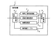
この発明を構成する暗号装置の一例を図1を用いて説明する。図において、1は学習機能付き暗号装置、2は通信データを暗号/復号する暗号/復号処理部、3は通信データを透過的に中継する透過中継処理部、4は通信データを廃棄する廃棄処理部、8は通信データの処理方法を示す暗号鍵テーブルで、図22に示すように通信データの宛先端末、送信元端末のペア毎に通信データの処理方法を登録する。
通信データの処理方法には、暗号/復号処理、透過中継処理、廃棄処理の3種類があり、暗号/復号の場合は、暗号/復号に使用する暗号鍵のIDが暗号鍵テーブル8に設定され、透過中継処理、廃棄処理の場合は、それぞれの処理方法が暗号鍵テーブル8に登録される。
【0019】
6は暗号鍵テーブル8の自動学習処理部で、受信した通信データの送信元端末と宛先端末のペアに対応して暗号鍵テーブル8に処理方法が登録していなかった場合に自動学習処理が起動される。
5はパブリックポートで、7はローカルポートである。
これらポートは暗号装置が通信データを暗号するのか復号するのかを識別するもので、暗号/復号処理の指定があった場合、暗号装置は、パブリックポート5から受信した通信データを復号し、ローカルポート7に送信する。また、ローカルポート7から受信した通信データを暗号化し、パブリックポート5に送信する。
9、10は送受信処理部で、通信データの受信処理、送信処理を実施する。
【0020】
次に動作について説明する。例えば、暗号装置1がローカルポート7から通信データを受信した場合、ローカルポート側の送受信処理部9は、通信データの宛先端末アドレスと送信元端末アドレスに対応する処理方法が暗号鍵テーブル8に登録されているか検索し、登録されていた場合、送受信処理部9はその処理方法に従い、暗号/復号処理部2、透過中継処理部3、廃棄処理部4のいずれかに処理を引き継ぐ。即ち処理方法に暗号鍵のIDが登録されていたなら、受信した通信データを暗号/復号処理部2へ渡す。処理方法に透過中継処理が登録されていたなら、透過中継処理部3へ受信した通信データを渡す。処理方法に廃棄処理が登録されていたなら、廃棄処理部4へ受信した通信データを渡す。
暗号/復号処理部2が通信データを受けたなら暗号鍵IDに従い、通信デ−タを暗号処理してパブリックポート側の送受信処理部10へ渡す。
【0021】
透過中継処理部3が通信データを受けたならその通信デ−タをパブリックポート側の送受信処理部10へ渡す。
廃棄処理部4が通信データを受けたならその通信データを廃棄する。
通信データを受けた送受信処理部10はパブリックポート5に渡し、パブリックポート5が通信データを送信する。
暗号装置1がパブリックポート5から通信データを受信した場合も同様に、送受信処理部10は通信データの宛先端末アドレスと送信元端末アドレスに対応する処理方法が暗号鍵テーブル8に登録されているか検索し、登録されていた場合、送受信処理部10はその処理方法に従い、暗号/復号処理部2、透過中継処理部3、廃棄処理部4のいずれかに処理を引き継ぐ。そして、暗号/復号処理部2が通信データを受けたなら暗号鍵IDに従い通信デ−タを復号処理してロ−カルポート側の送受信処理部9へ渡す。
【0022】
透過中継処理部3が通信データを受けたならその通信デ−タをロ−カルポート側の送受信処理部9へ渡す。
廃棄処理部4が通信データを受けたならその通信データを廃棄する。
通信データを受けた送受信処理部9はロ−カルポート7に渡し、ロ−カルポート7が通信データを送信する。
上記例において、もし暗号鍵テーブル8に処理方法が登録されていなかった場合には、自動学習処理部6に通知し、自動学習処理部6が他の暗号装置と連係して暗号鍵の学習を行なう。
【0023】
次に、本発明の、上記暗号装置を用いた暗号鍵学習機能を持つ暗号通信システムについて説明する。
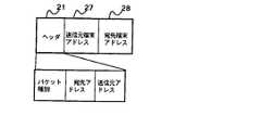
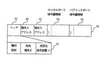
図2は、鍵探索パケットおよび鍵探索応答パケットのフォーマットを示す。
図2において、21はヘッダで、パケット種別、鍵探索パケットの宛先アドレス、送信元アドレス、などを含む。22は暗号装置1が受信した通信データの送信元端末のアドレス、23は暗号装置1が受信した通信データの宛先端末のアドレスである。24はローカルポート暗号鍵情報で、鍵探索パケットをローカルポート7から受信した暗号装置1が自身の持つ暗号鍵のIDを設定する。25はパブリックポート暗号鍵情報で、鍵探索パケットをパブリックポート5から受信した暗号装置1が自身の持つ暗号鍵のIDを設定する。26は鍵探索パケットおよび鍵探索応答パケットのデ−タ部で、送信元端末アドレス22、宛先端末アドレス23、ローカルポート暗号鍵情報24およびパブリックポート暗号鍵情報25から構成される。
【0024】
図3は端末A、B,C,Dを収容するネットワークの構成例を示すもので、暗号装置11はIDが1の、暗号装置12はIDが3の、暗号装置13はIDが1およびIDが2の、暗号装置14はIDが3の、暗号装置15はIDが2の暗号鍵を保有しており、暗号復号時にはそれぞれのIDに対応した暗号鍵を使用する。即ち、各暗号装置に割り当てる暗号鍵は、あらかじめ配送して登録されており、各暗号装置は、自身の持つ暗号鍵の暗号鍵IDを内部に一つまたは複数個保持する。また初期の時点では各装置内の暗号鍵テーブル8には、鍵情報がなにも登録されていないものとする。
なお、図中のLポートは、ローカルポート7、Pポートはパブリックポート5を示す。 また、図3の暗号装置11のパブリックポート5には暗号装置12のパブリックポート5と暗号装置14のパブリックポート5が接続されている。他は、ローカルポート7に対しパブリックポート5が接続されている。
【0025】
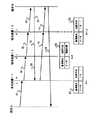
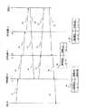
次に、図3における端末Aから端末Bへ通信する際に、端末Aから受信した通信データの送信元端末と宛先端末のペアに対応して暗号鍵テーブル8に処理方法が何も登録していなかった場合に、暗号鍵テーブル8を学習するための鍵探索パケットのシーケンスを図4に示す。
図において、31は暗号装置11から送信される鍵探索パケット、32は暗号装置12が鍵探索パケット31に暗号装置12の暗号鍵のIDを追加した鍵探索パケット、33は暗号装置13が鍵探索パケット32に暗号装置13の暗号鍵のIDを追加した鍵探索パケット、35は端末Bからの鍵探索応答パケットで、鍵探索パケット33が収集した暗号鍵のIDを各暗号装置1に知らせるパケットである。
【0026】
41は端末Aからの通信データで、ヘッダ21と送信元端末アドレスと宛先端末アドレスとデータとを有する。42は通信データ41のデータ部を暗号化した通信データである。
83は暗号装置13の暗号鍵テ−ブルで、通信端末A−端末B間は処理方法が暗号/復号で暗号鍵のIDが1であることを示す。82は暗号装置12の暗号鍵テ−ブルで、通信端末A−端末B間は処理方法が透過中継であることを示す。81は暗号装置11の暗号鍵テ−ブルで、通信端末A−端末B間は処理方法が暗号/復号で暗号鍵のIDが1であることを示す。
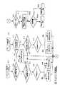
図5は暗号装置が鍵探索応答パケットを受信したときの処理フロ−チャ−トである。
なお、暗号鍵テ−ブル81〜83に処理方法が何も登録されていないものとする。
【0027】
次に動作を説明する。まず、図4に示すように、端末Aより端末B宛の通信データ41が送信される。通信データ41をローカルポート7から受信した暗号装置11は内部の暗号鍵テーブル81を検索し、端末A−B間の通信の処理方法が登録されていないので、鍵探索パケット31を編集してパブリックポート5へ送信すると共に、受信した通信データ41を通信デ−タバッファ(図示せず)に格納しておく。
なお、暗号装置11は、鍵探索パケット31を図6に示すように編集する。即ち、受信した通信データ41に基づいて、端末Aアドレスを送信元端末アドレス22に、端末Bアドレスを宛先端末アドレス23に、自身の持つ暗号鍵のIDである1をローカルポート暗号鍵情報24に設定し、パブリックポート暗号鍵情報25には何も設定しない。また、ヘッダにはパケット種別に鍵探索パケットを、鍵探索パケットの送信元アドレスに暗号装置11のアドレスを、宛先アドレスに端末Bのアドレスをセットする。
【0028】
鍵探索パケット31をパブリックポート5から受信した暗号装置12は、図7に示すように、自身の持つ唯一の暗号鍵のIDである3をパブリックポート暗号鍵情報25に追加設定し、鍵探索パケット32をローカルポート7へ転送する。鍵探索パケット32をパブリックポート5から受信した暗号装置13は、図8に示すように、自身の持つ暗号鍵のIDである1と2をパブリックポート暗号鍵情報25内に追加設定して、鍵探索パケット33をローカルポート7へ転送する。
鍵探索パケット33を受信した端末Bは、鍵探索パケット33のデータ部26を鍵探索応答パケット35にコピーする。そして、図9に示す鍵探索応答パケット35を暗号装置13経由11に送信する。ただし、鍵探索応答パケット35のヘッダ21にパケット種別が鍵探索応答パケット、送信元が端末Bのアドレス、宛先が暗号装置11のアドレスを設定し送信する。
【0029】
暗号装置13は、鍵探索応答パケット35をローカルポート7から受信すると(図5のステップS1)、暗号装置13は、自分自身の暗号鍵のIDである1または2と同じIDがローカルポート暗号鍵情報24に設定されているかどうか検索する(ステップS2)。
本例の場合、暗号装置11の設定したIDである1が鍵探索応答パケットのローカルポート暗号鍵情報24に設定されているので、暗号装置13は、図4の暗号鍵テーブル83に端末A−端末B間の通信データをIDが1の暗号鍵で暗号/復号することを登録し(ステップS3)、通信データバッファに送信すべき通信データがなく(ステップS4)、鍵探索応答パケット35のヘッダ21の宛先アドレスが自暗号装置13ではないので(ステップS6)、受信した鍵探索応答パケット35を暗号装置12に中継する(ステップS8)。
【0030】
暗号装置12は、鍵探索応答パケット35をローカルポート7から受信すると(図5のステップS1)、暗号装置12は、自分自身の暗号鍵のIDである3と同じ暗号鍵のIDが鍵探索応答パケット35のローカルポート暗号鍵情報24に設定されているかどうか検索する(ステップS2)。
本例の場合、同じIDを見つけることができないので、暗号装置12は、鍵探索応答パケット35のローカルポート暗号鍵情報24にある暗号鍵IDと同じ暗号鍵IDがパブリックポート暗号鍵情報25にあるか調べる(ステップS13)。
そして、図9に示すように暗号装置11の暗号鍵IDの1と暗号装置13の暗号鍵IDの1が一致するので、暗号装置12は、図4の暗号鍵テ−ブル82に端末A−端末B間の通信データを透過的に中継することを暗号鍵テーブル82に登録し(ステップS14)、通信データバッファに送信すべき通信データがなく(ステップS4)、鍵探索応答パケット35のヘッダ21の宛先アドレスが自暗号装置12ではないので(ステップS6)、受信した鍵探索応答パケット35を暗号装置11に中継する(ステップS8)。
【0031】
暗号装置11は、鍵探索応答パケット35をパブリックポート5から受信すると(ステップS11)、自分自身の持つ暗号鍵のIDである1と同じIDが鍵探索応答パケット35のパブリックポート暗号鍵情報25に設定されているかどうか検索する(ステップS12)。
本例の場合、暗号装置13が設定した2つの暗号鍵のうちで、IDが1の暗号鍵が鍵探索応答パケット35のパブリックポート暗号鍵情報25に設定されているため、暗号装置11は、図4の暗号鍵テーブル81に端末A−端末B間の通信データをIDが1の暗号鍵で暗号/復号することを暗号鍵テーブル81に登録する(ステップS3)。
【0032】
そして、暗号装置11は、通信データバッファに送信すべき通信データ41があるので(ステップS4)、通信データ41を暗号鍵テーブル81の内容に従い、暗号/復号処理部2で、暗号鍵1を用いて暗号化して通信データ42として端末B宛て送信する(ステップS5)。
次に、受信した鍵探索応答パケット35のヘッダ21に宛先アドレスは、暗号装置11となっているので(ステップS6)、暗号装置11は鍵探索応答パケット35を廃棄する(ステップS7)。
【0033】
暗号装置11で暗号化された通信データ42は、暗号装置12で暗号鍵テーブル82の内容に従い透過中継され、暗号装置13では、暗号鍵テーブル83の内容に従い、パブリックポート5からの通信データ42を暗号鍵1で復号し、復号した通信データ1をローカルポート7経由端末Bへ送信する。
端末Bから端末Aへの通信データ43は、暗号装置13で暗号鍵テーブル83の内容に従い、ローカルポート7からの通信データ43を暗号鍵1により暗号され、暗号装置12では暗号鍵テーブル82の内容に従い、透過的に中継されて、暗号装置11では暗号鍵テーブル81の内容に従い、パブリックポート5からの通信データ43を暗号鍵1により復号されてローカルポート7経由端末Aへ達する。
【0034】
上記例では、鍵探索パケットを宛先端末に送信したが、宛先端末を収容する暗号装置宛であってもよい。この場合、鍵探索パケットは中継経路上の暗号装置の暗号鍵情報を収集して、宛先端末を収容する暗号装置から、鍵探索応答パケットを中継経路上の暗号装置に通知する。
また、鍵探索パケットは送信元端末側の暗号装置からではなく、宛先端末を収容する暗号装置から発信させてもよい。この場合、送信元端末側の暗号装置から宛先端末を収容する暗号装置に鍵探索パケットを送出するよう指示し、指示された暗号装置から送出された鍵探索パケットは中継経路上の暗号装置の暗号鍵情報を収集し、送信元端末を収容する暗号装置から、鍵探索応答パケットを中継経路上の暗号装置に通知する。
以上により通信相手の暗号鍵がわからない状態から鍵探索パケットを用いて、端末間の通信経路上の暗号装置の鍵情報を収集し、収集した鍵情報に基づいて、暗号鍵情報を自動学習し、端末間の通信データを各暗号装置が暗号/復号、透過中継するので、人手により暗号通信ができるよう端末間の通信経路上の暗号装置に暗号鍵情報を設定するより、操作ミスが無く、ネットワ−ク管理が容易である。
図3における暗号装置11、13、15の機能を端末A、B、Cに内蔵させることによっても同様の効果を得ることができる。
【0035】
実施の形態2.
本実施の形態は二重暗号の動作を説明する。
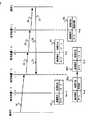
図10は、図3における端末Bから端末Cへ通信する場合、各暗号装置1が鍵探索パケットと鍵探索応答パケットにより暗号鍵テーブル8を学習するシーケンスを示したものである。図10において、41は端末Bから送信された通信データ、42は通信データ41を暗号化した通信データ、43は端末Cから端末Bへの通信データである。31〜34は暗号装置13から送信され暗号装置12、14、15を中継し端末Cに送られる鍵探索パケット、35は鍵探索応答パケットで、端末Cから送信され暗号装置15、14、12を中継する。
【0036】
82は暗号装置12の暗号鍵テ−ブルで、通信端末B−端末C間は処理方法が暗号/復号で暗号鍵のIDが3であることを示す。83は暗号装置13の暗号鍵テ−ブルで、通信端末B−端末C間は処理方法が暗号/復号で暗号鍵のIDが2であることを示す。84は暗号装置14の暗号鍵テ−ブルで、通信端末B−端末C間は処理方法が暗号/復号で暗号鍵のIDが3であることを示す。85は暗号装置15の暗号鍵テ−ブルで、通信端末B−端末C間は処理方法が暗号/復号で暗号鍵のIDが2であることを示す。
図5は暗号装置が鍵探索応答パケットを受信したときの処理フロ−チャ−トである。
【0037】
次に動作を説明する。まず、暗号鍵テ−ブル82〜85に処理方法が何も登録されていないものとする。
端末Bが通信データ41を送信すると、通信データ41を受信した暗号装置13は、自身の暗号鍵テーブル83に端末B−端末C間のデータの処理方法が登録されているか調べ登録されていないので、実施の形態1の時と同様に、鍵探索パケットのローカルポート暗号鍵情報24に自身の暗号鍵のID1、2を設定した鍵探索パケット31を送信する。ただし、鍵探索パケット31のヘッダ21にはパッケット種別に鍵探索パケットを、鍵探索パケットの送信元に暗号装置13のアドレスを、宛先に端末Cのアドレスを設定し、暗号装置12経由端末Cに送信する。
【0038】
探索パッケット31をローカルポート7から受信した暗号装置12は、鍵探索パケット31のローカルポート暗号鍵情報24に自身の持つ暗号鍵のID3を追加した鍵探索パケット32を送信する。
暗号装置14は、パブリックポート5から受信した鍵探索パケット32のパブリックポート暗号鍵情報25に自身の持つ暗号鍵のID3を追加した鍵探索パケット33を送信する。
暗号装置15は、パブリックポート5から受信した鍵探索パケット33のパブリックポート暗号鍵情報25に自身の持つ暗号鍵のID2を追加した鍵探索パケット34を送信する。
【0039】
次に、暗号装置15から自端末宛の鍵探索パケット34を受信した端末Cは、鍵探索パケット34のデータ部26を鍵探索応答パケット35のデータ部26にコピーする。そして、図11に示す鍵探索応答パケット35を暗号装置15経由端末B宛てに送信する。ただし、鍵探索応答パケット35のヘッダ21にはパケット種別に鍵探索応答パケットを、送信元に端末Cのアドレス、宛先に暗号装置13のアドレスを設定し送信する。
【0040】
暗号装置15は、ローカルポート7から鍵探索応答パケット35を受信すると(図5のステップS1)、自分自身の暗号鍵のIDである2と同じ暗号鍵のIDが鍵探索応答パケット35のローカルポート暗号鍵情報24に設定されているかどうか検索する(ステップS2)。
本例の場合、暗号装置15の設定したIDである2が鍵探索応答パケット35のローカルポート暗号鍵情報24に設定されているので、暗号装置15は、図10の暗号鍵テーブル85に端末B−端末C間の通信データ41をIDが2の暗号鍵で暗号/復号することを登録し(ステップS3)、通信データバッファに送信すべき通信データ41がなく(ステップS4)、鍵探索応答パケット35のヘッダ21の宛先アドレスが自暗号装置15ではないので(ステップS6)、受信した鍵探索応答パケット35を暗号装置14に中継する(ステップS8)。
【0041】
以下、同様に図5のフローチャートに従うと暗号装置14は、ローカルポート7から鍵探索応答パケット35を受信すると、鍵探索応答パケット35のローカルポート暗号鍵情報24に設定されている暗号鍵のIDを検索し、IDが3の鍵を得て自身の暗号鍵テーブル84に、端末B−端末C間の通信データを、IDが3の暗号鍵で暗号/復号することを登録し、鍵探索応答パケット35を暗号装置12に中継する。
【0042】
また、暗号装置12は、パブリックポート5から鍵探索応答パケット35を受信すると、自分自身の暗号鍵のIDである3と同じ暗号鍵IDが鍵探索応答パケット35のパブリックポート暗号鍵情報25に設定されているかどうか検索し、ID3の鍵が同一なので、自身の暗号鍵テーブル82に、端末B−端末C間の通信データを、IDが3の暗号鍵で暗号/復号することを登録し、暗号装置13に中継する。
暗号装置13は、パブリックポート5から鍵探索応答パケット35を受信すると、自分自身の暗号鍵のIDである1または2と同じ暗号鍵IDが鍵探索応答パケット35のパブリックポート暗号鍵情報25に設定されている暗号鍵のIDを検索し、ID2の鍵が同一なので、自身の暗号鍵テーブル83に、端末B−端末C間の通信データを、IDが2の暗号鍵で暗号/復号することを登録する。
【0043】
続いて、実施の形態1と同様に、暗号装置13は、通信デ−タバッファ(図示せず)に格納しておいたローカルポート7からの通信データ41を暗号鍵テーブル83の内容に従い、暗号/復号処理部2で、暗号鍵2を用いて暗号化し、その暗号化した通信データ42をパブリックポート5から暗号装置12経由端末C宛に送信する。また、鍵探索応答パケット35のヘッダ21内の宛先アドレスは、暗号装置13となっているので鍵探索応答パケット35は、暗号装置13によって廃棄される。
【0044】
暗号装置13で暗号化された通信データ42を、ローカルポート7から受信した暗号装置12は暗号鍵テーブル82の内容に従い、暗号鍵3により暗号化し、暗号装置14で暗号鍵テーブル84の内容に従い、パブリックポート5経由暗号鍵3により復号され、暗号装置15では暗号鍵テーブル85の内容に従い、パブリックポート5からの通信データを暗号鍵2により復号され、ローカルポート7経由端末Cへ達する。
【0045】
端末Cから端末Bへの通信データ43は、暗号装置15で暗号鍵テーブル85の内容に従い、ローカルポート7からの通信データ43を暗号鍵2により暗号され、暗号装置14で暗号鍵テーブル84の内容に従い、ローカルポート7からの通信データ43を暗号鍵3により暗号され、暗号装置12では暗号鍵テーブル82の内容に従い、パブリックポート5からの通信データ43を暗号鍵3により復号されて、暗号装置13では暗号鍵テーブル83の内容に従い、パブリックポート5からの通信データ43を暗号鍵2により復号されてローカルポート7経由端末Bへ達する。
【0046】
以上により、暗号装置13および15で暗号化した通信データをさらに暗号装置12および14で暗号化するので機密性の高い暗号通信ができる。
なお、端末B、C間で一度暗号化したら再度暗号化しないよう暗号装置12および14で暗号/復号処理をせず、透過中継処理をするようにしてもよい。従って、暗号/復号による通信データの遅延を減少できる。
図3における暗号装置11、13、15の機能を端末A、B、Cに内蔵させることによっても同様の効果を得ることができる。
【0047】
実施の形態3.
図3に示すように、端末A−端末C間で通信を行なう場合、暗号装置11、14、15で保持する暗号鍵のIDが1、3、2で、一致するものがないときの動作を説明する。
まず、図12に示すように、端末Aより端末C宛の通信データ41が送信される。通信データ41をローカルポート7から受信した暗号装置11は内部の暗号鍵テーブル81を検索し、端末A−B間の通信の処理方法が登録されていない場合、鍵探索パケット31を編集してパブリックポート5へ送信すると共に、受信した通信データ41を通信デ−タバッファに格納しておく。
【0048】
そして、暗号装置11は、鍵探索パケット31を受信した通信データ41に基づいて、以下のように編集する。 即ち、端末Aアドレスを送信元端末アドレス22に、端末Cアドレスを宛先端末アドレス23に、自身の持つ暗号鍵のIDである1をローカルポート暗号鍵情報24に設定し、パブリックポート暗号鍵情報25には何も設定しない。また、ヘッダ21にはパケット種別に鍵探索パケットを、鍵探索パケットの送信元アドレスに暗号装置11のアドレスを、宛先アドレスに端末Cのアドレスを設定して暗号装置14経由端末C宛に送信する。
暗号装置11が発信した鍵探索パケット31は暗号装置14、15でパブリックポート鍵情報25に自暗号鍵IDが付加されて端末Cに達する。端末Cは、鍵探索パケットのデ−タ部26を図13に示すように、鍵探索応答パケット35にコピ−し、ヘッダ21にはパケット種別が鍵探索応答パケット、送信元が端末Cのアドレス、宛先が暗号装置11のアドレスを設定した、鍵探索応答パケット35を暗号装置15経由暗号装置11宛てに送信する。
【0049】
次に、図5は暗号装置が鍵探索応答パケットを受信するときの処理フロ−チャ−トである。このフロ−チャ−トに従い説明する。
暗号装置15は、ローカルポート7から鍵探索応答パケット35を受信すると(図5のステップS1)、自分自身の暗号鍵のIDである2と同じ暗号鍵のIDが鍵探索応答パケット35のローカルポート暗号鍵情報24に設定されているかどうか検索する(ステップS2)。
本例の場合、暗号装置15が持つ暗号鍵ID2と同じ暗号鍵IDが鍵探索応答パケット35のローカルポート暗号鍵情報24に設定されていないので、ロ−カルポ−ト暗号鍵情報24とパブリックポート暗号鍵情報25に同じ暗号鍵IDがあるか調べ(ステップ13)、ないのでローカルポート暗号鍵情報24またはパブリックポート暗号鍵情報25に暗号鍵のIDが何も設定されていなか調べ(ステップ15)、ともに設定されているので暗号鍵テーブル85に廃棄処理を登録する。そして、ステップS4に進み、通信データバッファに送信すべき通信デ−タはなく、宛先アドレスが自暗号装置ではないので(ステップS6)受信した鍵探索応答パケット35を暗号装置14に中継する(ステップS8)。
【0050】
以下、同様に暗号装置14は、ローカルポート7から鍵探索応答パケット35を受信すると、暗号鍵テーブル84に廃棄処理を登録し、鍵探索応答パケット35を暗号装置11に中継する。
暗号装置11は、パブリックポート5から鍵探索応答パケット35を受信すると、自身の暗号鍵テーブル81に、端末A−端末C間の通信データは廃棄処理するよう登録する。そして、送信バッファに格納されている通信デ−タを暗号鍵テーブル81に従い廃棄する。
【0051】
また、鍵探索応答パケット35のヘッダ21内の宛先アドレスが、暗号装置11となっているので、暗号装置11は鍵探索応答パケット35を廃棄する。
上記例では、図13にも示したとおり、一致する暗号鍵のIDが存在しないため、暗号装置11、14、15の暗号鍵テーブル81、84、85には、端末A−端末C間の通信データを廃棄することが登録される。この結果、端末A−端末C間の通信データは、各暗号装置によって廃棄される。
以上、端末A−端末C間の中継経路上の各暗号装置に同一の暗号鍵IDがない場合、各暗号装置は端末A−端末C間の通信データを廃棄するので、不正アクセス、機密の漏洩防止ができる。
【0052】
実施の形態4.
一つの暗号装置を介して二つの端末間で通信を行なう例を図3、図14、図5を用いて説明する。
図14は、図3における端末Aから端末Dへの通信が実施される際に、暗号鍵テーブルを学習するために実施される鍵探索パケットのシーケンスを示したものである。41は、端末Aから送信された通信データ、31は、暗号装置11から送信される鍵探索パケット、35は、端末Dから送信される鍵探索応答パケット、41、43は、暗号鍵テーブル学習後に実施される端末A−端末D間の通信デ−タを示す。81は暗号装置11の暗号鍵テーブルである。
図5は暗号装置が鍵探索応答パケットを受信したときの処理フロ−チャ−トである。
【0053】
端末Aからの通信データ41をローカルポート7から受信した暗号装置11は、自身の持つ暗号鍵テーブル81に端末A−端末D間の通信データの処理方法が登録されていないため、図15に示す鍵探索パケット31を編集し端末D宛て送信する。また、通信デ−タ41を通信デ−タバッファに格納する。
【0054】
なお、暗号装置11は、鍵探索パケット31を図15に示すように編集する。即ち、受信した通信データ41に基づいて、端末Aアドレスを送信元端末アドレス22に、端末Dアドレスを宛先端末アドレス23に、自身の持つ暗号鍵のIDである1をローカルポート暗号鍵情報24に設定し、パブリックポート暗号鍵情報25には何も設定しない。また、ヘッダ21にはパケット種別に鍵探索パケットを、鍵探索パケットの送信元アドレスに暗号装置11のアドレスを、宛先アドレスに端末Dのアドレスをセットする。
鍵探索パケット31を受信した端末Dは、鍵探索応答パケット35のデータ部に、鍵探索パケットのデータ部をコピーして、ヘッダ21にはパケット種別に鍵探索応答パケット35を、宛先アドレスに暗号装置11のアドレスを、送信元アドレスに端末Dのアドレスを設定して暗号装置11に送信する。
【0055】
鍵探索応答パケット35をパブリックポート5から受信した(図5のステップS11)暗号装置11は、自分自身の持つ暗号鍵のIDである1と同じIDがパブリックポート暗号鍵情報25に設定されているかどうか検索する(ステップS12)。
本実施の形態の場合、設定されていないので、ローカルポート暗号鍵情報24とパブリックポート暗号鍵情報25の両方に同じ暗号鍵IDがあるか調べ(ステップS13)、パブリックポート暗号鍵情報25には何も設定されていない。つまり、暗号装置11の送信した鍵探索パケット31をパブリックポート5から受信した暗号装置はいないということ(復号する暗号装置が存在しない)であり、このため、暗号装置11では、暗号鍵テーブル81に端末A−端末D間の通信データを透過中継することが登録される(ステップS14)。
【0056】
そして、通信デ−タバッファに格納しておいた通信データ41を暗号鍵テーブル81に従い端末A−端末D間の通信データを透過中継する(ステップS5)。また、自暗号装置宛て(ステップS6)の鍵探索応答パケット35を廃棄する(ステップS7)。この結果、通信デ−タ41は暗号されずに端末Dに到達する。また、端末Dからの通信データ43は暗号装置11で暗号鍵テーブル81に従い透過中継されて暗号化されずに端末Aに達する。
【0057】
以上、鍵探索応答パケット35のパブリックポート鍵情報25に暗号鍵IDがない場合、暗号装置は暗号鍵テーブル81に端末A−端末D間の通信データを透過中継するよう登録するので、一つの暗号装置を介して暗号化せず端末間通信ができる。
上記例では、暗号化せずに通信できるようにしたが、通信を許可しないとしてもよい。
【0058】
実施の形態5.
以上の実施の形態1、2では、各暗号装置が初期状態、即ち暗号鍵テーブルに何も設定されていない状態での例を説明してきたが、各暗号装置が暗号鍵テーブル8の学習後、電源断などにより通信経路の途中の暗号装置の暗号鍵テーブル8が消去されてしまった場合、暗号通信ができなくなる例を以下に示す。
【0059】
例えば、実施の形態2による方法で、図3における端末Bと端末C間で通信中に、障害により暗号装置12がすでに学習済みの暗号鍵テーブル82を消去してしまった場合の動作を図16を用いて説明する。
なお、図中82aは消去してしまった暗号鍵テーブル、82bは再登録した暗号鍵テーブルである。図5は暗号装置が鍵探索応答パケットを受信したときの処理フロ−チャ−トである。
端末Bから端末C宛ての通信デ−タ41をローカルポート7から受信すると暗号装置13は暗号鍵テーブル83を参照して処理方法に暗号鍵2が登録されているので、暗号鍵2で通信デ−タ41を暗号化して送出する。暗号化した通信デ−タ41を受信した暗号装置12は暗号鍵テーブル82aを参照すると端末Bと端末C間は処理方法が登録されていないので、鍵探索パケット32を編集し、暗号装置14、15経由端末C宛てに送出する。
【0060】
なお、暗号装置12は鍵探索パケット32のローカルポート暗号鍵情報24に暗号装置12の暗号鍵ID3を設定し、鍵探索パケット32のヘッダ21にはパケット種別に鍵探索パケットを、送信元アドレスに暗号装置12のアドレスを、宛先アドレスに端末Cのアドレスを設定し、暗号装置14経由端末C宛て送信する。
そして、鍵探索パケット32をパブリックポート5から受信した暗号装置14は、自暗号鍵のIDを鍵探索パケット32のパブリックポート暗号鍵情報25に付加した鍵探索パケット33を暗号装置15経由端末C宛て送信する。
鍵探索パケット33をパブリックポート5から受信した暗号装置15は、自暗号鍵のIDを鍵探索パケット33のパブリックポート暗号鍵情報25に付加した鍵探索パケット34を端末Cに送信する。
【0061】
鍵探索パケット34を受信した端末Cは、鍵探索パケット34のデータ部26を図17のように鍵探索応答パケット35のデータ部26にコピーし、鍵探索応答パケット35のヘッダ21にはパケット種別に鍵探索応答パケットを、送信元に端末Cのアドレスを、宛先に暗号装置12のアドレスを設定し、その鍵探索応答パケット35を暗号装置15経由暗号装置12宛てに送出する。
鍵探索応答パケット35をローカルポート7から受信した(図5のステップS1)暗号装置15は、自分自身の暗号鍵のIDである2と同じIDがローカルポート暗号鍵情報24に設定されているか調べ(ステップS2)、ないのでローカルポート暗号鍵情報24とパブリックポート暗号鍵情報25に同じ暗号鍵のIDがあるか調べ(ステップS13)、あるので暗号鍵テーブル85に処理方法として透過中継処理を登録する(ステップS14)。送信すべき通信デ−タがなく(ステップS4)、自暗号装置宛てではないので(ステップS6)、鍵探索応答パケット35を暗号装置14に中継する。(ステップS8)。
【0062】
以下同様に、鍵探索応答パケット35を受信した暗号装置14は暗号鍵テーブル84に端末B−C間では処理方法が暗号/復号処理で暗号鍵のIDが3を登録し、鍵探索応答パケット35を暗号装置12に中継する。
鍵探索応答パケット35をパブリックポート5から受信した(図5のステップS11)暗号装置12は、自分自身の暗号鍵のIDである3と同じIDがパブリックポート暗号鍵情報25に設定されているか調べ(ステップS12)、あるので暗号鍵テーブル82に処理方法として暗号/復号処理で暗号鍵のIDが3を登録し、通信デ−タバッファに送信すべき通信デ−タがあるか調べ(ステップS4)、あるので通信デ−タを送信する(ステップS5)。鍵探索応答パケット35は自暗号装置12宛てであるので(ステップS6)、鍵探索応答パケット35を廃棄する(ステップS7)。
【0063】
従って、暗号装置12は暗号鍵テーブル82bに端末B−C間では処理方法が暗号/復号処理で暗号鍵のIDが3を登録する。暗号装置14は暗号鍵テーブル84に端末B−C間では処理方法が暗号/復号処理で暗号鍵のIDが3を登録する。暗号装置15は暗号鍵テーブル85に端末B−C間では処理方法が透過中継を登録する。
そして、端末Bから送信された通信データは、暗号装置13でIDが2の暗号鍵で暗号され、暗号装置12でIDが3の暗号鍵で暗号され、暗号装置14でIDが3の暗号鍵で復号され、暗号装置15で透過中継されるため、端末Cに到達するデータは、IDが2の暗号鍵で暗号された状態となっており、通信が不可能である。
【0064】
本実施の形態では暗号装置が暗号鍵テーブルを消去しても、混乱を起こさず復旧させる方法について、以下に説明する。
図3における端末Bと端末C間で通信中に、例えば、障害により暗号装置12がすでに学習済みの暗号鍵テーブル82を消去してしまった場合のシーケンスを図18に示す。
図18において、82aは消去してしまった暗号装置12の暗号鍵テーブル、82bは再登録した暗号装置12の暗号鍵テーブル、83は暗号装置13の暗号鍵テーブル、84は暗号装置14の暗号鍵テーブル、85は暗号装置15の暗号鍵テーブルである。
また、暗号装置13の暗号鍵テーブル83は端末Bと端末C間は暗号鍵2を、暗号装置14の暗号鍵テーブル84は端末Bと端末C間は暗号鍵3を、暗号装置15の暗号鍵テーブル85は端末Bと端末C間は暗号鍵2を登録しているものとする。
【0065】
次に図19は鍵探索要求パケットのフォーマットを示し、21はヘッダで、パケット種別、鍵探索要求パケットの宛先アドレス(本例では、端末B)、送信元アドレス(本例では、暗号装置12)などを含む。27は、暗号装置が受信した通信データの送信元端末、28は、暗号装置が受信した通信データの宛先端末のアドレスである。 図20は鍵探索要求パケット51の例で、送信元端末アドレス27には端末Bアドレス、宛先端末アドレス28には、端末Cアドレスが設定される。
図21は鍵探索要求応答パケット52の例で、送信元端末アドレス27には端末Bアドレス、宛先端末アドレス28には、端末Cアドレスが設定される。
【0066】
次に動作を説明する。
端末Bからの通信データ41をローカルポート7から受信した暗号装置13は、暗号鍵テーブル83に登録された処理方法に従い、IDが2の暗号鍵で暗号化した通信データ41を暗号装置12へ中継する。暗号化された通信データ41を受信した暗号装置12は、暗号鍵テーブル82aに端末B−端末C間の処理方法が登録されていないので、図20に示すように、暗号装置12は鍵探索要求パケット51の送信元に端末Bのアドレスを、宛先に端末Cのアドレスを設定し、ヘッダ21にはパケット種別が鍵探索要求パケット、送信元が端末Bのアドレス、宛先が暗号装置12のアドレスを設定した鍵探索要求パケット51を通信データの送信元端末すなわち端末B宛に送信すると共に、通信データ41を通信データバッファに格納しておく。
【0067】
鍵探索要求パケット51を受信した暗号装置13は、受信パケットが端末B宛の鍵探索要求パケット51であるため、これを端末Bに中継する。鍵探索要求パケット51を受信した端末Bは、図20、図21に示すように、送信元端末アドレス27と宛先端末アドレス28を鍵探索要求応答パケット52の送信元端末アドレス27と宛先端末アドレス28にコピーし、鍵探索応答パケット52のヘッダ21にはパケット種別が鍵探索要求応答パケット、送信元が端末Bのアドレス、宛先が暗号装置12のアドレスを設定し送信する。
鍵探索要求応答パケット52を受信した暗号装置13は、鍵探索パケット31の送信元端末アドレス27には鍵探索要求応答パケット52に設定されていた送信元端末アドレス27を、宛先端末アドレス28には、鍵探索要求応答パケット52に設定されていた送信元端末アドレス28をコピーする。
【0068】
ここでは、送信元端末アドレス27に端末Bのアドレスが、宛先端末アドレス28に端末Cのアドレスが設定される。
また、ヘッダ21にはパケット種別に鍵探索パケットを、送信元に暗号装置13のアドレスを、宛先に端末Cのアドレスを設定し、鍵探索パケット31を送信する。
そして、暗号装置13は鍵探索要求応答パケット52のヘッダ21の宛先アドレスが何であっても関係無く、受信した鍵探索要求応答パケット52を廃棄する。
この後の鍵探索パケットの処理過程は、実施の形態2と同じで、暗号装置13は、鍵探索パケット31を暗号装置12、14、15経由端末C宛てに送出する。ただし、鍵探索パケット31を発信した暗号装置13と中継した暗号装置12、14、15は自暗号鍵のIDを鍵探索パケット31、32、33に付加した鍵探索パケット32、33、34を送信する。即ち、暗号装置13、12は自暗号鍵のIDをロ−カルポ−ト暗号鍵情報24に、暗号装置14、15は自暗号鍵のIDをパブリックポ−ト暗号鍵情報25に、設定する。
【0069】
鍵探索パケット34を受信した端末Cは鍵探索パケットのデータ部26を鍵探索応答パケット35のデータ部26にコピーする。そして、鍵探索応答パケット35を暗号装置15経由暗号装置13宛てに送信する。ただし、鍵探索応答パケット35のヘッダ21にパケット種別が鍵探索応答パケット、送信元が端末Cのアドレス、宛先が暗号装置13のアドレスを設定し送信する。
【0070】
暗号装置15は、ローカルポート7から鍵探索応答パケット35を受信すると(図5のステップS1)、自分自身の暗号鍵のIDである2と同じ暗号鍵のIDが鍵探索応答パケット35のローカルポート暗号鍵情報24に設定されているかどうか検索する(ステップS2)。
本例の場合、暗号装置15の設定したIDである2が鍵探索応答パケット35のローカルポート暗号鍵情報24に設定されているので、暗号装置15は、図18の暗号鍵テーブル85に端末B−端末C間の通信データ41をIDが2の暗号鍵で暗号/復号することを登録し(ステップS3)、通信データバッファに送信すべき通信データ41がなく(ステップS4)、鍵探索応答パケット35のヘッダ21の宛先アドレスが自暗号装置15ではないので(ステップS6)、受信した鍵探索応答パケット35を暗号装置14に中継する(ステップS8)。
【0071】
以下、同様に図5のフローチャートに従うと暗号装置14は、ローカルポート7から鍵探索応答パケット35を受信すると、鍵探索応答パケット35のローカルポート暗号鍵情報24に設定されている暗号鍵のIDを検索し、IDが3の鍵を得て自身の暗号鍵テーブル84に、端末B−端末C間の通信データを、IDが3の暗号鍵で暗号/復号することを登録し、鍵探索応答パケット35を暗号装置12に中継する。
【0072】
暗号装置12は、パブリックポート5から鍵探索応答パケット35を受信すると、鍵探索応答パケット35のパブリックポート暗号鍵情報25に設定されている暗号鍵のIDを検索し、IDが3の鍵を得て、自身の暗号鍵テーブル82に、端末B−端末C間の通信データを、IDが3の暗号鍵で暗号/復号することを登録する。
そして、通信デ−タバッファに格納しておいたローカルポート7からの通信データ41を暗号鍵テーブル82の内容に従い、暗号/復号処理部2で、暗号鍵3を用いて暗号化し、その暗号化した通信データ42を暗号装置14経由端末Cに送信する。
【0073】
また、鍵探索応答パケット35を暗号装置13に中継する。
暗号装置13は、パブリックポート5から鍵探索応答パケット35を受信すると、鍵探索応答パケット35のパブリックポート暗号鍵情報25に設定されている暗号鍵のIDを検索し、IDが2の鍵を得て、自身の暗号鍵テーブル83に、端末B−端末C間の通信データを、IDが2の暗号鍵で暗号/復号することを登録する。
続いて、実施の形態1と同様に、暗号装置13は、鍵探索応答パケット35のヘッダ21内の宛先アドレスが、暗号装置13となっているので、鍵探索応答パケット35を廃棄する。
【0074】
暗号装置13で暗号化された通信データ42を、ローカルポート7から受信した暗号装置12は暗号鍵テーブル82の内容に従い、暗号鍵3により暗号化し、暗号装置14で暗号鍵テーブル84の内容に従い、パブリックポート5経由暗号鍵3により復号され、暗号装置15では暗号鍵テーブル85の内容に従い、パブリックポート5からの通信データを暗号鍵2により復号され、ローカルポート7経由端末Cへ達する。 従って、端末Bからの通信データ41を中継するとき、暗号装置13は暗号鍵テ−ブル83に従い、暗号鍵のID2で暗号化し、暗号装置12は暗号鍵テ−ブル82bに従い暗号鍵のID3で暗号化し、暗号装置14は暗号鍵テ−ブル84に従い暗号鍵のID3で復号し、暗号装置15は暗号鍵テ−ブル85に従い、暗号鍵のID2で復号し、端末Cに送る。
【0075】
端末Cから端末Bへの通信データ43は、暗号装置15で暗号鍵テーブル85の内容に従い、ローカルポート7からの通信データ43を暗号鍵2により暗号され、暗号装置14で暗号鍵テーブル84の内容に従い、ローカルポート7からの通信データ43を暗号鍵3により暗号され、暗号装置12では暗号鍵テーブル82の内容に従い、パブリックポート5からの通信データ43を暗号鍵3により復号されて、暗号装置13では暗号鍵テーブル83の内容に従い、パブリックポート5からの通信データ43を暗号鍵2により復号されてローカルポート7経由端末Bへ達する。
以上により通信相手の暗号鍵がわからない状態から鍵探索パケットを用いることにより相方向の暗号通信ができる。
【0076】
以上のように鍵探索パケットは、通信データの送信元端末に一番近い暗号装置13から送信するようにしたので暗号装置が暗号鍵テ−ブルを消去しても矛盾なく暗号通信ができ暗号鍵学習もできる。
また、本実施の形態では、通信データの送信元端末に対して鍵探索要求パケットを送信したが、通信データの宛先に対して鍵探索要求パケットを送信しても同等の効果が得られる。
【0077】
また、鍵探索要求パケットを送信せず、はじめに暗号装置12から通信データの送信元端末である端末B宛に鍵探索パケットを送信し、暗号装置13の持つ暗号鍵のIDの情報を暗号装置12で一旦収集し、収集した情報を持つ鍵探索パケット(あたかも、暗号装置13から送信され、暗号装置12が自身の暗号鍵のIDを追加設定したように、鍵探索パケットのデータ部を設定した鍵探索パケット)を暗号装置12から送信することによっても同等の効果が得られる。
上記例では、鍵探索パケットを宛先端末に送信したが、宛先端末を収容する暗号装置宛であってもよい。この場合、鍵探索パケットは中継経路上の暗号装置の暗号鍵情報を収集して、宛先端末を収容する暗号装置から、鍵探索応答パケットを中継経路上の暗号装置に通知する。
また、鍵探索パケットは送信元端末側の暗号装置からではなく、宛先端末を収容する暗号装置から発信させてもよい。この場合、送信元端末側の暗号装置から宛先端末を収容する暗号装置に鍵探索パケットを送出するよう指示し、指示された暗号装置から送出された鍵探索パケットは中継経路上の暗号装置の暗号鍵情報を収集し、送信元端末を収容する暗号装置から、鍵探索応答パケットを中継経路上の暗号装置に通知する。
【0078】
実施の形態6.
本実施の形態は実施の形態5において、所定時間通信を行わない通信端末の組み合わせ(以下端末ペアと称す)に対応する暗号鍵情報を暗号鍵テーブルから削除するものである。
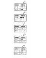
暗号鍵テ−ブルの端末ペア毎に、初期値が図22に示すように例えば600秒の保持時間を持たせ、図1の自動学習処理部6がこの保持時間を定周期、例えば1秒毎にカウントダウンし、カウント値がゼロになったら、その端末ペアの暗号鍵情報の登録を暗号鍵テーブルから削除する。削除後、暗号鍵テーブルに削除した端末ペアの暗号鍵情報が未登録の状態で、再び同じ端末ペアが通信データの中継の要求を発生すれば、実施の形態5が示すように、暗号鍵学習処理を行い、データ通信を再開する。
【0079】
また、保持時間がゼロでないとき、即ち600秒以内に、端末ペアで通信データの中継の要求が発生すれば、保持時間を初期値例えば600秒に設定し、暗号鍵情報の処理方法を暗号鍵テーブルに保持し続ける。
上記実施の形態5で登録した暗号鍵テーブルの登録に対して、図22に示すように保持時間制限を過ぎたものは登録を消去することによって、暗号鍵テーブルに通信頻度の少ない端末ペアの暗号鍵情報を記憶する必要なく、暗号鍵テーブルの記憶容量を少なくできる。
また、端末が移動し、通信経路が変更された場合でも、通信経路変更前の暗号鍵情報は所定時間後消去するので、通信経路の変更が容易にできる。
また、使用する暗号鍵、あるいは、暗号化、透過中継、廃棄などの中継条件により、保有時間の初期値を変えてもよい。
実施の形態7.
透過中継または廃棄を指定する外部端末通信モードを暗号通信装置対応に設け、二つの端末間で通信している中継区間で、暗号中継していない区間があれば、その区間内の暗号通信装置は外部端末通信モードを透過または廃棄に設定することにより、通信データを透過処理するか廃棄処理できるようにするものである。まず、一つの暗号装置を介して、二つの端末間で通信を行なう例について説明し、次に複数の暗号装置を介して二つの端末間で通信を行なう例について説明する。
【0080】
図23は、この発明を構成する暗号装置の一例である。1〜10は、実施の形態1と同様で、説明を省く。111は、外部端末通信モード設定部で、暗号装置対応に設け、通信データを透過処理するか、廃棄処理するか、を指定するものである。暗号鍵テーブルを学習する際に、自動学習処理部6によって参照される。なお、鍵探索パケットおよび鍵探索応答パケットは、実施の形態1で説明した図2と同一のフォーマットである。
【0081】
図24は端末A、B,Cを収容するネットワークの構成例を示すもので、11はIDが1の暗号鍵を保有している暗号装置、12はIDが1の暗号鍵を保有している暗号装置、13はIDが2の暗号鍵を保有している暗号装置で、暗号復号時にはそれぞれのIDに対応した暗号鍵を使用する。即ち、各暗号装置に割り当てる暗号鍵は、あらかじめ配送して登録されており、各暗号装置は、自身の持つ暗号鍵の暗号鍵IDを内部に一つまたは複数個保持する。また初期の時点では各装置内の暗号鍵テーブル8には、鍵情報がなにも登録されていないものとする。なお、図中のLポートは、ローカルポート7、Pポートはパブリックポート5を示す。また、図24の暗号装置11のパブリックポート5には暗号装置12のパブリックポート5が接続されている。他は、ローカルポート7に対しパブリックポート5が接続されている。
【0082】
次に、一つの暗号装置を介して、二つの端末間で通信を行なう例について動作を説明する。
初めに、図24における暗号装置11の外部端末通信モード設定部111が、透過中継に設定されており、端末Aから通信を開始し端末Cと通信する際の、暗号鍵テーブル81の学習処理について示す。
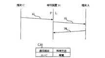
図25は、端末Aから端末Cへ通信する際に、暗号装置11の暗号鍵テーブル81に、端末Aから受信した通信データの送信元端末と宛先端末のペアに対応した処理方法が登録されていなかった場合の、暗号鍵テーブル81を学習するための鍵探索パケットのシーケンスを示す。
41、43は通信データ、31は、暗号装置11から送信される鍵探索パケット、35は、端末Cから送信される鍵探索応答パケットを示す。81は暗号装置11の暗号鍵テーブルである。
図26は暗号装置が鍵探索応答パケットを受信したときの処理フロ−チャ−トである。また、図中のLPIはローカルポート暗号鍵情報24を、PPIはパブリックポート暗号鍵情報25を示している。
なお、鍵探索パケットおよび鍵探索応答パケットのフォーマットは実施の形態1の図2に示すとおりである。
【0083】
次に、図25、図26を用いて動作を説明する。
端末Aからの通信データ41をローカルポート7から受信した暗号装置11は、内部の暗号鍵テーブル81を検索し、端末A−C間の通信の処理方法が登録されていないので、通信デ−タ41を通信デ−タバッファに格納する。そして、図27に示すように鍵探索パケットを編集する。即ち、鍵探索パケット31のヘッダ21にはパケット種別に鍵探索パケットと、宛先アドレスに宛先端末Cと、送信元アドレスに送信元暗号装置11とを設定し、端末Aアドレスを送信元端末アドレス22に、端末Cアドレスを宛先端末アドレス23に設定する。そして、ローカルポート暗号鍵情報24に暗号装置11自身が持つ暗号鍵IDである1を設定し、パブリックポート暗号鍵情報25になにも設定せずに鍵探索パケット31(図27)を端末C宛に送信する。
【0084】
鍵探索パケット31を受信した端末Cは、図28に示すように鍵探索パケットを編集する。即ち、鍵探索応答パケット35のデータ部に鍵探索応答パケット31のデータ部をコピーして、ヘッダ21には、パケット種別に鍵探索応答パケットを、宛先アドレスに暗号装置11のアドレスを、送信元アドレスに端末Cのアドレスを設定して暗号装置11に送信する。
【0085】
暗号装置11は、鍵探索応答パケット35をパブリックポート5から受信すると(図26のステップS11)、自分自身の持つ暗号鍵のIDである1と同じIDがパブリックポート暗号鍵情報25に設定されているかどうか検索する(ステップS12)。
本例の場合、設定されていないので、自暗号装置よりも先に暗号中継区間があるか、即ち自暗号装置よりも先に鍵探索パケットを受信し、ローカルポート暗号鍵情報24に情報を設定した暗号装置のうち、パブリックポート暗号鍵情報25に登録されている鍵IDと一致する鍵IDを持っているものが有るかを調べる。即ち、自暗号装置が暗号区間内か判定する。(ステップS13)。一致するものがない。即ち、自暗号装置が暗号区間内にないので、次に外部端末通信モード設定部111を参照する(ステップS14)と、外部端末通信モードは透過設定となっているので、暗号鍵テーブル81に端末A−端末C間の通信データを透過中継することを登録する(ステップS16)。
【0086】
そして、通信デ−タバッファに格納しておいた通信データ41を暗号鍵テーブル81に従い端末A−端末C間の通信データを透過中継する(ステップS21、S22)。また、自暗号装置宛て(ステップS23)の鍵探索応答パケット35を廃棄する(ステップS24)。この結果、通信デ−タ41は暗号されずに端末Cに到達する。また、端末Cからの通信データ43は暗号装置11で暗号鍵テーブル81に従い、透過中継されて暗号化されずに端末Aに達する。
以上、図25に示すシーケンスで、暗号装置11は端末Aと端末C間の通信データ41、43を暗号鍵テーブル81に従い、透過中継する。
【0087】
次に、上記例で暗号装置11の外部端末通信モードを廃棄に設定した場合の動作を説明する。
暗号装置11は上記図26のステップS14で外部端末通信モード設定部111を参照し、廃棄設定となっている場合には、暗号鍵テーブル81に端末A−端末C間の通信データを廃棄処理することを登録する(ステップS15)。
そして、通信デ−タバッファに格納しておいた通信データ41を暗号鍵テーブル81に従い廃棄する(ステップS21、S22)。また、自暗号装置宛て(ステップS23)の鍵探索応答パケット35を廃棄する(ステップS24)。
以上、図29に示すシーケンスで、暗号装置11は端末Aからの通信データ41を暗号鍵テーブル81に従い、廃棄する。
従って、暗号中継区間外の暗号装置11において、外部端末通信モード設定部111の設定により端末間の通信データを透過中継または廃棄できる。
【0088】
次に、複数の暗号装置を介して二つの端末間で通信を行なう例について説明する。
図24において、端末Aから端末Bへ通信する場合、暗号装置11と暗号装置12が同じ暗号鍵を持ち暗号中継区間を形成し、暗号装置13が異なる暗号鍵を持つと共に暗号装置13の外部端末通信モード設定部111が、透過中継設定されている例について説明する。
図30は、端末Aから端末Bへ通信する際に、暗号装置11の暗号鍵テーブル81に、端末Aから受信した通信データの送信元端末と宛先端末のペアに対応した処理方法が登録していなかった場合の、暗号鍵テーブル81を学習するための鍵探索パケットのシーケンスである。
図において、41、42、43、44は通信データ、31は鍵探索パケットで、暗号装置11から送信される。32は鍵探索パケットで、暗号装置12が鍵探索パケット31に暗号装置12の暗号鍵のIDを追加した鍵探索パケットである。
33は鍵探索パケットで、暗号装置13が鍵探索パケット32に暗号装置13の暗号鍵のIDを追加した鍵探索パケットである。35は端末Bからの鍵探索応答パケットである。また、それぞれ、81は暗号装置11の、82は暗号装置12の、83は暗号装置13の暗号鍵テーブルである。
【0089】
次に動作を説明する。
端末Aから端末B宛ての通信データ41をローカルポート7から受信した暗号装置11は、内部の暗号鍵テーブル81を検索し、端末A−B間の通信の処理方法が登録されていないので、通信デ−タ41を通信デ−タバッファに格納する。
【0090】
そして、図31に示すように鍵探索パケットを編集する。即ち、鍵探索パケット31のヘッダ21には、パケット種別に鍵探索パケットと、宛先アドレスに宛先端末Bと、送信元アドレスに送信元暗号装置11とを設定し、端末Aアドレスを送信元端末アドレス22に、端末Bアドレスを宛先端末アドレス23に設定する。そして、ローカルポート暗号鍵情報24に暗号装置11自身が持つ暗号鍵IDである1を設定し、パブリックポート暗号鍵情報25になにも設定せずに鍵探索パケット31(図31)を端末B宛に送信する。
鍵探索パケット31をパブリックポート5から受信した暗号装置12は、自身の持つ暗号鍵のIDである1をパブリックポート暗号鍵情報25内に追加設定して、鍵探索パケット32(図32)をローカルポート7へ転送する。
【0091】
鍵探索パケット32をパブリックポート5から受信した暗号装置13は、自身の持つ暗号鍵のIDである2をパブリックポート暗号鍵情報25内に追加設定して、鍵探索パケット33(図33)をローカルポート7へ転送する。
鍵探索パケット33を受信した端末Bは、データ部に鍵探索パケット33のデータ部をコピーして、図34で示す鍵探索応答パケット35を、暗号装置11へ送信する。この鍵探索応答パケット35のヘッダ21には、図34のように、パケット種別に鍵探索応答パケットが、宛先アドレスに暗号装置11のアドレスが、送信元アドレスに端末Bのアドレスが設定される。
【0092】
暗号装置13は、鍵探索応答パケット35をローカルポート7から受信すると(図26のステップS01)、自分自身の持つ暗号鍵のIDである2と同じIDがローカルポート暗号鍵情報24に設定されているかどうか検索する(ステップS02)。
本例の場合、設定されていないので、自暗号装置よりも後に暗号中継区間があるか、即ち自暗号装置よりも後に鍵探索パケットを受信し、パブリックポート暗号鍵情報25に情報を設定した暗号装置のうち、ローカルポート暗号鍵情報24に登録されている鍵IDと一致する鍵IDを持っているものが有るかを調べる(ステップ03)。
本例の場合、一致するものがない。即ち、自暗号装置が暗号区間内にないので、次に暗号装置13は、外部端末通信モード設定部111を参照し(ステップS04)、透過設定となっているので、暗号鍵テーブル83に端末A−端末B間の通信データを透過中継することを登録する(ステップS06)。
また、通信データバッファに送信すべき通信データがなく(ステップS21)、鍵探索応答パケット35のヘッダ21の宛先アドレスが自暗号装置13ではないので(ステップS23)、受信した鍵探索応答パケット35を暗号装置11に中継する(ステップS25)。
【0093】
暗号装置12は、鍵探索応答パケット35をローカルポート7から受信すると(ステップS11)、自分自身の暗号鍵のIDである1と同じ暗号鍵のIDが鍵探索応答パケット35のローカルポート暗号鍵情報24に設定されているかどうか検索する(ステップS12)。
本例の場合、暗号装置11が設定した暗号鍵ID1が鍵探索応答パケット35のローカルポート暗号鍵情報24に設定されているため、暗号装置12は、図29の暗号鍵テーブル82に端末A−端末B間の通信データをIDが1の暗号鍵で暗号/復号することを登録する(ステップS7)。
また、通信データバッファに送信すべき通信データがなく(ステップS21)、鍵探索応答パケット35のヘッダ21の宛先アドレスが自暗号装置12ではないので(ステップS23)、受信した鍵探索応答パケット35を暗号装置11に中継する(ステップS25)。
【0094】
暗号装置11は、鍵探索応答パケット35をパブリックポート5から受信すると(ステップS11)、自分自身の持つ暗号鍵のIDである1と同じ鍵IDが鍵探索応答パケット35のパブリックポート暗号鍵情報25に設定されているかどうか検索する(ステップS12)。
本例の場合、暗号装置12が設定した暗号鍵ID1が鍵探索応答パケット35のパブリックポート暗号鍵情報25に設定されているため、暗号装置11は、図30の暗号鍵テーブル81に端末A−端末B間の通信データをIDが1の暗号鍵で暗号/復号することを暗号鍵テーブル81に登録する(ステップS7)。
そして、暗号装置11は、通信データバッファに送信すべき通信データ41があるので(ステップS21)、通信データ41を暗号鍵テーブル81の内容に従い、暗号/復号処理部2で、暗号鍵1を用いて暗号化して通信データ42として端末B宛て送信する(ステップS22)。
次に、受信した鍵探索応答パケット35のヘッダ21に宛先アドレスは、暗号装置11となっているので(ステップS23)、暗号装置11は鍵探索応答パケット35を廃棄する(ステップS24)。
【0095】
その結果、通信データ41は、暗号装置11で暗号鍵テーブル81の内容に従い暗号鍵1で暗号化され通信データ42となり、通信データ42は、暗号装置12で暗号鍵テーブル82の内容に従い暗号鍵1で復号され通信データ41に戻り、暗号装置13では、暗号鍵テーブル83の内容に従い通信データ41を透過中継し、端末Bへ達する。また、端末Bからの通信データ43は、暗号鍵テーブルの登録に従って、暗号装置13で透過中継され、暗号装置12で暗号鍵1で暗号化され(通信データ44)、暗号装置11で暗号鍵1で復号され、端末Aに達する。
従って、暗号中継区間外の暗号装置13において、外部端末通信モード設定部111を透過中継設定にすれば、通信データを透過中継できる。
【0096】
次に、図24において、端末Aから端末Bへ通信する場合、暗号装置11と暗号装置12が同じ暗号鍵を持ち暗号中継区間を形成し、暗号装置13が異なる暗号鍵を持つと共に暗号装置13の外部端末通信モード設定部111が、廃棄設定されている場合の暗号鍵テーブル83の学習処理について示す。
図35は、その際の鍵探索パケットのシーケンスであるが、端末A,端末B、暗号装置11、暗号装置12の動作、及び暗号装置13が鍵探索パケットを受信するまでの動作については、上記例と同じなので、ここでは省略し、暗号装置13が、鍵探索応答パケットをローカルポート7から受信した時の動作について説明する。
本例も、図26の暗号装置の処理フロ−チャ−トにより説明する。
【0097】
暗号装置13は、鍵探索応答パケット35をローカルポート7から受信すると(図26のステップS01)、自分自身の持つ暗号鍵のIDである2と同じIDがローカルポート暗号鍵情報24に設定されているかどうか検索する(ステップS02)。
本例の場合、設定されていないので、自暗号装置よりも後に暗号中継区間があるか、即ち自暗号装置より後に鍵探索パケットを受信し、パブリックポート暗号鍵情報25に情報を設定した暗号装置のうち、ローカルポート暗号鍵情報24に登録されている鍵IDと一致する鍵IDを持っているものが有るかを調べる(ステップ03)。
本例の場合、そのような暗号装置は無く、暗号装置13は暗号中継区間内に無いので、次に外部端末通信モード設定部111を参照し(ステップS04)、廃棄設定となっているので、暗号装置13は暗号鍵テーブル83に端末Aー端末B間の通信データを廃棄することを登録する(ステップS05)。そして、通信データバッファに送信すべき通信データがなく(ステップS21)、鍵探索応答パケット35のヘッダ21の宛先アドレスが自暗号装置13ではないので(ステップS23)、受信した鍵探索応答パケット35を暗号装置12に中継する(ステップS25)。
【0098】
暗号装置12、暗号装置11には、それぞれの暗号鍵テーブル82、81に、端末A−端末B間の通信データを、暗号鍵1によって、暗号/復号することを登録する。
【0099】
その結果、端末Aから端末B宛ての通信データ41は、暗号装置11で暗号鍵テーブル81に従って暗号鍵1で暗号化され(通信データ42)、暗号装置12で暗号鍵テーブル82の内容に従い暗号鍵1で復号され、暗号装置13では、暗号鍵テーブル83の内容に従い、通信データ41は廃棄される。
従って、暗号中継区間外の暗号装置13において、外部端末通信モード設定部111を廃棄設定にすれば、通信データを廃棄できる。
【0100】
以上のように、端末Aから端末Bへ通信する場合、暗号装置11と暗号装置12が同じ暗号鍵を用いて暗号中継区間を形成し、暗号装置13が異なる暗号鍵を持つため暗号化されていない中継区間を形成するので、暗号装置13の外部端末通信モード設定部111の設定により端末間の通信データを透過中継または廃棄できる。
なお、鍵探索パケットは実施の形態5のように、通信データの送信元端末に対して一番近い暗号装置から送出してもよい。
【0101】
実施の形態8.
実施の形態7では、外部端末通信モードに透過中継および廃棄を設けた例を説明したが、本実施の形態は外部端末通信モードに半透過を追加した例について説明する。
ここでは、外部端末通信モードの半透過とは、通信データの伝送方向によって透過中継するか廃棄するかを制御するもので、端末ペア間の通信において、通信を開始した端末とその相手端末との通信経路が、暗号化されている中継区間から、暗号化されていない中継区間を経て相手端末に接続された場合、外部端末通信モードが半透過に設定されていれば、暗号化されていない中継区間の暗号装置では通信データを廃棄し、逆に、暗号化されていない中継区間から、暗号化されている中継区間を経て相手端末に接続された場合、外部端末通信モードが半透過に設定されていれば、透過に設定し暗号化されていない中継区間の暗号装置では通信データを透過中継するものである。
また、暗号化された中継区間がない例として、一つの暗号装置を介して、二つの端末間で通信を行う場合も、暗号装置は外部端末通信モードの半透過に対して同様に動作する。
【0102】
まず、半透過に設定された一つの暗号装置を介して、二つの端末間で通信を行なう例について説明し、次に半透過に設定された複数の暗号装置を介して二つの端末間で通信を行なう例について説明する。
一つの暗号装置の場合については、
暗号装置11の外部端末通信モード設定部111が、半透過設定されていて、暗号装置11のローカルポート7側に接続している端末Aが通信を開始する場合と、パブリックポート5側に接続している端末Cが通信を開始する場合とについて暗号鍵テーブルの学習処理の動作を説明する。
【0103】
初めに、図24における暗号装置11の外部端末通信モード111設定部が、半透過設定されていて、暗号装置11のローカルポート7に接続している端末Aが通信を開始する場合の、暗号鍵テーブルの学習処理について説明する。
図36は暗号装置の処理フローチャートで、実施の形態7の図26のステップS04とステップS14に半透過の判定を追加したものである。
図37は、鍵探索のシーケンスであるが、暗号装置11が鍵探索応答パケットを受信するまでは、実施の形態7(図25)と同様なので、ここでは説明を省略する。暗号装置11が、鍵探索応答パケットをパブリックポート5から受信してからの処理について、図36の暗号装置の処理フロ−チャ−トにより説明する。
【0104】
暗号装置11は、鍵探索応答パケット35をパブリックポート5から受信すると(図36のステップS11)、自分自身の持つ暗号鍵のIDである1と同じIDがパブリックポート暗号鍵情報25に設定されているかどうか検索する(ステップS12)。
本例の場合、設定されていないので、自暗号装置よりも先に鍵探索パケットを受信し、ローカルポート暗号鍵情報24に情報を設定した暗号装置のうち、パブリックポート暗号鍵情報25に登録されている鍵IDと一致する鍵IDを持っているものが有るかを調べる(ステップ13)。
【0105】
本例の場合、そのような暗号装置は無い。次に外部端末通信モード設定部111を参照し、それが半透過設定になっており、かつ、鍵探索応答パケット35をパブリックポート5から受信しているので(ステップS14)、暗号鍵テーブル81に端末A−端末C間の通信データを透過することを登録する(ステップS16)。
そして、通信デ−タバッファに格納しておいた通信データ41を暗号鍵テーブル81に従い透過中継する(ステップS21、S22)。また、自暗号装置宛て(ステップS23)の鍵探索応答パケット35を廃棄する(ステップS24)。この結果、通信デ−タ41は暗号化されずに端末Cに到達する。また、端末Cからの通信データ43は、暗号装置11で暗号鍵テーブル81に従い透過中継されて暗号化されずに端末Aに達する。
従って、暗号装置11の外部端末通信モード111設定部が、半透過設定されていて、暗号装置11のローカルポート7に接続している端末Aが通信を開始する場合は透過中継にできる。
【0106】
次に、図24における暗号装置11の外部端末通信モード設定部111が、半透過設定されていて、暗号装置11のパブリックポート5側に接続している端末Cが通信を開始する場合の、暗号鍵テーブルの学習処理について示す。
図38は、鍵探索のシーケンスである。本例でも、各暗号装置が鍵探索応答パケットを受信した時の処理については、図36の処理フロ−チャ−トにより説明する。
【0107】
端末Cからの通信データ41をパブリックポート5から受信した暗号装置11は、内部の暗号鍵テーブル81を検索し、端末A−C間の通信の処理方法が登録されていないので、通信デ−タ41を通信デ−タバッファに格納し、鍵探索パケットのパブリックポート暗号鍵情報25に、自身のアドレス及び自身の暗号鍵のID1を設定した鍵探索パケット31を送信する。この際、鍵探索パケット31のヘッダ21にはパケット種別に鍵探索パケットを、鍵探索パケットの送信元に暗号装置11のアドレスを、宛先に端末Aのアドレスを設定し、端末Aに送信する。
【0108】
鍵探索パケット31を受信した端末Aは、図39に示すように鍵探索応答パケットを編集する。即ち、端末Aは鍵探索応答パケット35のデータ部に鍵探索パケット31のデータ部をコピーし、鍵探索応答パケット35(図39)を、暗号装置11へ送信する。この際、この鍵探索応答パケット35のヘッダ21には、図39のように、パケット種別に鍵探索応答パケットが、宛先アドレスに暗号装置11のアドレスが、送信元アドレスに端末Aのアドレスが設定される。
【0109】
暗号装置11は、鍵探索応答パケット35をローカルポート7から受信すると(図36のステップS01)、自分自身の持つ暗号鍵のIDである1と同じIDがローカルポート暗号鍵情報24に設定されているかどうか検索する(ステップS02)。
本例の場合、設定されていないので、自暗号装置よりも後に鍵探索パケットを受信し、パブリックポート暗号鍵情報25に情報を設定した暗号装置のうち、ローカルポート暗号鍵情報24に登録されている鍵IDと一致する鍵IDを持っているものが有るかを調べる(ステップ03)。
本例の場合、そのような暗号装置は無い。次に外部端末通信モード設定部111を参照し、それが半透過になっており、かつ、鍵探索応答パケット35をローカルポート7から受信しているので(ステップS04)、暗号鍵テーブル81に端末A−端末C間の通信データを廃棄することを登録する(ステップS05)。
【0110】
そして、暗号装置11は通信デ−タバッファに格納しておいた通信データ41を暗号鍵テーブル81に従い廃棄する(ステップS21、S22)。また、自暗号装置宛て(ステップS23)の鍵探索応答パケット35を廃棄する(ステップS24)。
従って、暗号装置11の外部端末通信モード111設定部が、半透過設定されていて、暗号装置11のパブリックポート5に接続している端末Bが通信を開始する場合は廃棄にできる。
【0111】
以上のように、暗号装置の外部端末通信モード設定部111に半透過を設定することにより、ローカルポート7側から通信が開始された場合には透過中継処理し、パブリックポート5側から通信が開始された場合には廃棄処理することができる。
従って、パブリックポート5側に収容されている端末からの発信は通信データを廃棄するので、外部の端末からの不正アクセスを防止できる。
【0112】
次に、半透過に設定された複数の暗号装置を介して、二つの端末間で通信を行なう例について説明する。
即ち、半透過に設定された複数の暗号装置を介して、端末Aから開始し端末Bと通信する場合と、端末Bから開始し端末Aと通信する場合について、動作を説明する。
まず、図24において、端末Aから端末Bへ通信する場合、暗号装置11と暗号装置12が同じ暗号鍵を持ち暗号中継区間を形成し、暗号装置13が異なる暗号鍵を持つと共に暗号装置13の外部端末通信モード設定部111が、半透過設定されている例について説明する。
【0113】
図40は、端末Aから端末Bへ通信する際に、暗号装置11の暗号鍵テーブル81に、端末Aから受信した通信データの送信元端末と宛先端末のペアに対応した処理方法が登録していなかった場合の、暗号鍵テーブル81を学習するための鍵探索パケットのシーケンスである。
図において、41、42は通信データ、31は鍵探索パケットで、暗号装置11から送信される。32は鍵探索パケットで、暗号装置12が鍵探索パケット31に暗号装置12の暗号鍵のIDを追加した鍵探索パケットである。
33は鍵探索パケットで、暗号装置13が鍵探索パケット32に暗号装置13の暗号鍵のIDを追加した鍵探索パケットである。35は端末Bからの鍵探索応答パケットである。また、それぞれ、81は暗号装置11の、82は暗号装置12の、83は暗号装置13の暗号鍵テーブルである。
【0114】
次に動作を説明する。
端末Aから端末B宛ての通信データ41をローカルポート7から受信した暗号装置11は、内部の暗号鍵テーブル81を検索し、端末A−B間の通信の処理方法が登録されていないので、通信デ−タ41を通信デ−タバッファに格納する。
【0115】
そして、図31に示すように鍵探索パケットを編集する。即ち、鍵探索パケット31のヘッダ21には、パケット種別に鍵探索パケットと、宛先アドレスに宛先端末Bと、送信元アドレスに送信元暗号装置11とを設定し、端末Aアドレスを送信元端末アドレス22に、端末Bアドレスを宛先端末アドレス23に設定する。そして、ローカルポート暗号鍵情報24に暗号装置11自身が持つ暗号鍵IDである1を設定し、パブリックポート暗号鍵情報25になにも設定せずに鍵探索パケット31(図31)を端末B宛に送信する。
鍵探索パケット31をパブリックポート5から受信した暗号装置12は、自身の持つ暗号鍵のIDである1をパブリックポート暗号鍵情報25内に追加設定して、鍵探索パケット32(図32)をローカルポート7へ転送する。
【0116】
鍵探索パケット32をパブリックポート5から受信した暗号装置13は、自身の持つ暗号鍵のIDである2をパブリックポート暗号鍵情報25内に追加設定して、鍵探索パケット33(図33)をローカルポート7へ転送する。
鍵探索パケット33を受信した端末Bは、データ部に鍵探索パケット33のデータ部をコピーして、図34で示す鍵探索応答パケット35を、暗号装置11へ送信する。この鍵探索応答パケット35のヘッダ21には、図34のように、パケット種別に鍵探索応答パケットが、宛先アドレスに暗号装置11のアドレスが、送信元アドレスに端末Bのアドレスが設定される。
【0117】
暗号装置13は、鍵探索応答パケット35をローカルポート7から受信すると(図36のステップS01)、自分自身の持つ暗号鍵のIDである2と同じIDがローカルポート暗号鍵情報24に設定されているかどうか検索する(ステップS02)。
本例の場合、設定されていないので、自暗号装置よりも後に鍵探索パケットを受信し、パブリックポート暗号鍵情報25に情報を設定した暗号装置のうち、ローカルポート暗号鍵情報24に登録されている鍵IDと一致する鍵IDを持っているものが有るかを調べる(ステップ03)。即ち、自暗号装置が暗号区間内か判定する。本例の場合、一致するものがない。即ち、自暗号装置が暗号区間内にない。
【0118】
次に暗号装置13は、外部端末通信モード設定部111を参照し(ステップS04)、半透過設定になっており、かつ、鍵探索応答パケット35をローカルポート7から受信しているので、暗号鍵テーブル83に端末A−端末B間の通信データを廃棄することを登録する(ステップS05)。
また、通信データバッファに送信すべき通信データがなく(ステップS21)、鍵探索応答パケット35のヘッダ21の宛先アドレスが自暗号装置13ではないので(ステップS23)、受信した鍵探索応答パケット35を暗号装置11に中継する(ステップS25)。
【0119】
暗号装置12は、鍵探索応答パケット35をローカルポート7から受信すると(ステップS01)、自分自身の暗号鍵のIDである1と同じ暗号鍵のIDが鍵探索応答パケット35のローカルポート暗号鍵情報24に設定されているかどうか検索する(ステップS02)。
本例の場合、暗号装置11が設定した暗号鍵ID1が鍵探索応答パケット35のローカルポート暗号鍵情報24に設定されているため、暗号装置12は、図29の暗号鍵テーブル82に端末A−端末B間の通信データをIDが1の暗号鍵で暗号/復号することを登録する(ステップS7)。
また、通信データバッファに送信すべき通信データがなく(ステップS21)、鍵探索応答パケット35のヘッダ21の宛先アドレスが自暗号装置12ではないので(ステップS23)、受信した鍵探索応答パケット35を暗号装置11に中継する(ステップS25)。
【0120】
暗号装置11は、鍵探索応答パケット35をパブリックポート5から受信すると(ステップS11)、自分自身の持つ暗号鍵のIDである1と同じ鍵IDが鍵探索応答パケット35のパブリックポート暗号鍵情報25に設定されているかどうか検索する(ステップS12)。
本例の場合、暗号装置12が設定した暗号鍵ID1が鍵探索応答パケット35のパブリックポート暗号鍵情報25に設定されているため、暗号装置11は、図40の暗号鍵テーブル81に端末A−端末B間の通信データをIDが1の暗号鍵で暗号/復号することを暗号鍵テーブル81に登録する(ステップS7)。
そして、暗号装置11は、通信データバッファに送信すべき通信データ41があるので(ステップS21)、通信データ41を暗号鍵テーブル81の内容に従い、暗号/復号処理部2で、暗号鍵1を用いて暗号化して通信データ42として端末B宛て送信する(ステップS22)。
次に、受信した鍵探索応答パケット35のヘッダ21に宛先アドレスは、暗号装置11となっているので(ステップS23)、暗号装置11は鍵探索応答パケット35を廃棄する(ステップS24)。
【0121】
その結果、通信データ41は、暗号装置11で暗号鍵テーブル81の内容に従い暗号鍵1で暗号化され通信データ42となり、通信データ42は、暗号装置12で暗号鍵テーブル82の内容に従い暗号鍵1で復号され通信データ41に戻り、暗号装置13では、暗号鍵テーブル83の内容に従い通信データ41を廃棄する。また、端末Bからの通信データ43は暗号装置13で廃棄される。
従って、端末Aから端末Bへ通信する場合、暗号装置11と暗号装置12が同じ暗号鍵を持ち暗号中継区間を形成し、暗号装置13が異なる暗号鍵を持つため暗号化されていない中継区間を形成するので、暗号装置13の外部端末通信モード設定部111を、半透過設定にすれば、端末Aと端末B間の通信データを廃棄できる。
【0122】
次に、図24において、端末Bから端末Aへ通信する場合、暗号装置11と暗号装置12が同じ暗号鍵を持ち暗号中継区間を形成し、暗号装置13が異なる暗号鍵を持つと共に、暗号装置13の外部端末通信モード設定部111が、半透過に設定されている場合の暗号鍵テーブル83の学習処理について示す。
図41は、その際の鍵探索パケットのシーケンス図である。
本例も、図36の鍵探索応答パケットの処理フロ−チャ−トにより説明する。
【0123】
通信網構成は図24と同じで端末Bから端末Aへ発信する場合のシーケンスを説明する。
図41は、端末Bから端末Aへ通信する際に、暗号装置13の暗号鍵テーブル83に、端末Bから受信した通信データの送信元端末と宛先端末のペアに対応した処理方法が登録していなかった場合の、暗号鍵テーブル83を学習するための鍵探索パケットのシーケンスを示す。
図において、41、42、43、44は通信データ、31は鍵探索パケットで、暗号装置13から送信される。32は鍵探索パケットで、暗号装置12が鍵探索パケット31に暗号装置12の暗号鍵のIDを追加した鍵探索パケットである。
33は鍵探索パケットで、暗号装置11が鍵探索パケット32に暗号装置11の暗号鍵のIDを追加した鍵探索パケットである。35は端末Aからの鍵探索応答パケットである。また、それぞれ、81は暗号装置11の、82は暗号装置12の、83は暗号装置13の暗号鍵テーブルである。
【0124】
次に動作を説明する。
端末Bから端末A宛ての通信データ41をローカルポート7から受信した暗号装置13は、内部の暗号鍵テーブル83を検索し、端末A−B間の通信の処理方法が登録されていないので、通信デ−タ41を通信デ−タバッファに格納する。
【0125】
そして、暗号装置13は、図42に示すように鍵探索パケットを編集する。即ち、鍵探索パケット31のヘッダ21には、パケット種別に鍵探索パケットと、宛先アドレスに宛先端末Aと、送信元アドレスに送信元暗号装置13とを設定し、端末Bアドレスを送信元端末アドレス22に、端末Aアドレスを宛先端末アドレス23に設定する。そして、ローカルポート暗号鍵情報24に暗号装置13自身が持つ暗号鍵IDである2を設定し、パブリックポート暗号鍵情報25になにも設定せずに鍵探索パケット31(図42)を端末A宛に送信する。
暗号装置12は、鍵探索パケット31をローカルポート7から受信し,自身の持つ暗号鍵のIDである1をローカルポート暗号鍵情報24内に追加設定して、鍵探索パケット32(図43)をパブリックポート5へ転送する。
【0126】
鍵探索パケット32をパブリックポート5から受信した暗号装置11は、自身の持つ暗号鍵のIDである1をパブリックポート暗号鍵情報25内に追加設定して、鍵探索パケット33(図44)をローカルポート7へ転送する。
鍵探索パケット33を受信した端末Aは、データ部に鍵探索パケット33のデータ部をコピーして、図45で示す鍵探索応答パケット35を、暗号装置11へ送信する。この鍵探索応答パケット35のヘッダ21には、図45のように、パケット種別に鍵探索応答パケットが、宛先アドレスに暗号装置13のアドレスが、送信元アドレスに端末Aのアドレスが設定される。
【0127】
暗号装置11は、鍵探索応答パケット35をローカルポート7から受信すると(図36のステップS01)、自分自身の持つ暗号鍵のIDである1と同じIDがローカルポート暗号鍵情報24に設定されているかどうか検索する(ステップS02)。
本例の場合、暗号装置12が設定した暗号鍵ID1が鍵探索応答パケット35のローカルポート暗号鍵情報24に設定されているため、暗号装置11は、図41の暗号鍵テーブル81に端末A−端末B間の通信データをIDが1の暗号鍵で暗号/復号することを登録する(ステップS7)。
また、通信データバッファに送信すべき通信データがなく(ステップS21)、鍵探索応答パケット35のヘッダ21の宛先アドレスが自暗号装置11ではないので(ステップS23)、受信した鍵探索応答パケット35を暗号装置13に中継する(ステップS25)。
【0128】
暗号装置12は、鍵探索応答パケット35をパブリックポート5から受信すると(ステップS11)、自分自身の暗号鍵のIDである1と同じ暗号鍵のIDが鍵探索応答パケット35のパブリックポート暗号鍵情報25に設定されているかどうか検索する(ステップS12)。
本例の場合、暗号装置11が設定した暗号鍵ID1が鍵探索応答パケット35のパブリックポート暗号鍵情報25に設定されているため、暗号装置12は、図41の暗号鍵テーブル82に端末A−端末B間の通信データをIDが1の暗号鍵で暗号/復号することを登録する(ステップS7)。
また、通信データバッファに送信すべき通信データがなく(ステップS21)、鍵探索応答パケット35のヘッダ21の宛先アドレスが自暗号装置12ではないので(ステップS23)、受信した鍵探索応答パケット35を暗号装置13に中継する(ステップS25)。
【0129】
暗号装置13は鍵探索応答パッケットをパブリックポート5から受信すると(ステップS11)、自分自身の持つ暗号鍵のIDである2と、同じ鍵IDがパブリックポート暗号鍵情報25に登録されているかを調べる(ステップS12)。本例の場合、設定されていないので、自暗号装置よりも先に暗号中継区間があるか、即ち自暗号装置より先に鍵探索パケットを受信し、ローカルポート暗号鍵情報24に情報を設定した暗号装置のうち、パブリックポート暗号鍵情報25に登録されている鍵IDと一致する鍵IDを持っているものが有るかを調べる(ステップ13)。本例の場合、一致するものがない。即ち、自暗号装置が暗号区間内にないので、次に暗号装置13は、外部端末通信モード設定部111を参照し(ステップS14)、半透過設定になっており、かつ、鍵探索応答パケット35をパブリックポート5から受信しているので、暗号鍵テーブル83に端末A−端末B間の通信データを透過することを登録する(ステップS16)。
【0130】
また、通信データバッファに送信すべき通信データがなく(ステップS21)、鍵探索応答パケット35のヘッダ21の宛先アドレスが自暗号装置13ではないので(ステップS23)、受信した鍵探索応答パケット35を暗号装置13に中継する(ステップS25)。
そして、暗号装置13は、通信データバッファに送信すべき通信データ41があるので(ステップS21)、通信データ41を暗号鍵テーブル83の内容に従い、透過中継して端末B宛て送信する(ステップS22)。
次に、受信した鍵探索応答パケット35のヘッダ21に宛先アドレスは、暗号装置13となっているので(ステップS23)、暗号装置13は鍵探索応答パケット35を廃棄する(ステップS24)。
【0131】
その結果、通信データバッファに格納しておいた端末Bからの通信データ41を暗号装置13は暗号鍵テーブル83の内容に従い、通信データ41を透過中継し、暗号装置12は暗号鍵テーブル82の内容に従い、通信データ41を暗号鍵1で暗号化して、通信データ42となり、暗号装置11は暗号鍵テーブル81の内容に従い、暗号鍵1で通信データ42を復号し通信データ41に戻し、端末Aに送信する。
また、端末Aからの通信データ43は、暗号鍵テーブルの登録に従って、暗号装置11で暗号鍵1により暗号化され、暗号装置12で暗号鍵1により復号され(通信データ44)、暗号装置13で透過中継され、端末Bに達する。
【0132】
従って、端末Bから端末Aへ通信する場合、暗号装置11と暗号装置12が同じ暗号鍵を持ち暗号中継区間を形成し、暗号装置13が異なる暗号鍵を持つため暗号化されていない中継区間を形成するので、暗号装置13の外部端末通信モード設定部111を、半透過設定にすれば端末Bと端末A間の通信データは透過中継できる。
【0133】
以上のように、発信端末Aから端末Bへ通信する場合、暗号化されていない中継区間の暗号装置は外部端末通信モード設定部111を、半透過設定にすれば、端末Aと端末B間の通信データを廃棄できる。
また、発信端末Bから端末Aへ通信する場合、暗号化されていない中継区間の暗号装置は外部端末通信モード設定部111を、半透過設定にすれば、端末Bから端末A間の通信データを透過中継できる。
なお、発信端末と半透過の関係は、端末Aが発信端末で暗号装置13が半透過に設定されている場合、図24に示すように端末Aを収容する暗号装置11からの鍵探索パケットは暗号装置13のパブリックポート5から受信され鍵探索応答パケットはローカルポート7から受信するので半透過は廃棄処理される。
逆に、端末Bが発信端末で暗号装置13が半透過に設定されている場合、端末Bを収容する暗号装置13からの鍵探索パケットに対する鍵探索応答パケットはパブリックポート5から受信するので半透過は透過中継処理される。
従って、外部端末通信モード設定部111を半透過に設定すれば、透過中継または廃棄を自動的に選択するので確実に不正アクセスを防止できる。
なお、鍵探索パケットは実施の形態5のように、通信データの送信元端末に対して一番近い暗号装置から送出してもよい。
【0134】
【発明の効果】
第1および第2の発明によれば、通信相手の暗号鍵がわからない状態から鍵探索パケットを用いて、端末間の通信経路上の暗号装置の鍵情報を収集し、収集した鍵情報に基づいて、暗号鍵情報を自動学習し、端末間の通信データを各暗号装置が暗号/復号、透過中継するので、人手により暗号通信ができるよう端末間の通信経路上の暗号装置に暗号鍵情報を設定するより、操作ミスが無く、ネットワ−ク管理が容易である。
【0135】
第3の発明によれば、鍵探索パケットは、通信データの送信元端末に一番近い暗号装置から送信するようにしたので暗号装置が暗号鍵テ−ブルを消去しても矛盾なく暗号通信ができ暗号鍵学習もできる。
【0136】
第4の発明によれば、通信相手の暗号鍵がわからない状態から鍵探索パケットを用いて、端末間の通信経路上の暗号装置の鍵情報を収集し、収集した鍵情報に基づいて、暗号鍵情報を自動学習し、端末間の通信データを各暗号装置が暗号/復号、透過中継するので、人手により暗号通信ができるよう端末間の通信経路上の暗号装置に暗号鍵情報を設定するより、操作ミスが無く、ネットワ−ク管理が容易である。
また、端末間の中継経路上の各暗号装置に同一の暗号鍵がない場合、各暗号装置はその端末間の通信データを廃棄するので、不正アクセス、機密の漏洩防止ができる。 また、2つの暗号装置間で暗号化した通信データをさらに別の暗号装置間で暗号化するので機密性の高い暗号通信ができる。
【0137】
第5の発明によれば、鍵探索応答パケットのパブリックポート暗号鍵情報に鍵がない場合、暗号装置は暗号鍵テーブルに端末ペア間の通信データを透過中継するよう登録するので、一つの暗号装置を介して暗号化せず端末間通信ができる。
【0138】
第6の発明によれば、暗号鍵テーブルに登録した端末間で、所定の保持時間制限を過ぎたものは登録を消去することによって、暗号鍵テーブルに通信頻度の少ない端末ペアの暗号鍵情報を記憶する必要なく、暗号鍵テーブルの記憶容量を少なくできる。 また、端末が移動し、通信経路が変更された場合でも、通信経路変更前の暗号鍵情報は所定時間後消去するので、通信経路の変更が容易にできる。
【0139】
第7の発明によれば、端末ペア間の通信において、同じ暗号鍵を持つ暗号装置が暗号中継区間を形成し、異なる暗号鍵を持つ暗号装置が暗号化されていない中継区間を形成する場合、暗号化されていない中継区間の暗号装置の外部端末通信モードの設定により端末間の通信データを透過中継または廃棄処理するので、アクセスの許可、禁止ができる。
【0140】
第8の発明によれば、端末ペア間の通信において、通信を開始した端末とその相手端末との通信経路が、暗号化されている中継区間から、暗号化されていない中継区間を経て相手端末に接続された場合、外部端末通信モードが半透過に設定されていれば、暗号化されていない中継区間の暗号装置では通信データを廃棄し、逆に、暗号化されていない中継区間から、暗号化されている中継区間を経て相手端末に接続された場合、外部端末通信モードが半透過に設定されていれば、半透過に設定し暗号化されていない中継区間の暗号装置では通信データを透過中継するので、外部端末通信モードを半透過に設定すれば、透過中継または廃棄を自動的に選択しアクセスの許可、禁止するので確実に不正アクセスを防止できる。
【図面の簡単な説明】
【図1】この発明による暗号装置の構成図である。
【図2】この発明による鍵探索パケットおよび鍵探索応答パケットのフレーム構成を示す図である。
【図3】この発明におけるネットワーク構成を示す図である。
【図4】この発明の実施の形態1におけるネットワーク構成において端末間で暗号通信を行う例を示すシーケンス図である。
【図5】この発明おける鍵探索応答パケットの処理フローを示す図である。
【図6】この発明の実施の形態1における鍵探索パケットのフレームを示す図である。
【図7】この発明の実施の形態1における鍵探索パケットのフレームを示す図である。
【図8】この発明の実施の形態1における鍵探索パケットのフレームを示す図である。
【図9】この発明の実施の形態1における鍵探索応答パケットのフレームを示す図である。
【図10】この発明の実施の形態2におけるネットワーク構成において、端末間で2重鍵の暗号通信を行う例を示すシーケンス図である。
【図11】この発明の実施の形態2における鍵探索応答パケットのフレームを示す図である。
【図12】この発明の実施の形態3におけるネットワーク構成において、複数の暗号装置を介して端末間で通信を行う場合、複数の暗号装置に同一の鍵がなければ暗号通信を行わない例を示すシーケンス図である。
【図13】この発明の実施の形態3における鍵探索応答パケットのフレームを示す図である。
【図14】この発明の実施の形態4におけるネットワーク構成において、一つの暗号装置を介して端末間で暗号通信を行う例を示すシーケンス図である。
【図15】この発明の実施の形態4における鍵探索応答パケットのフレームを示す図である。
【図16】この発明の実施の形態5におけるネットワーク構成において、暗号装置の暗号鍵テーブルが消去されたとき端末間で暗号通信が異常になるシーケンスを示す図である。
【図17】この発明の実施の形態5における鍵探索応答パケットのフレームを示す図である。
【図18】この発明の実施の形態6におけるネットワーク構成において、暗号装置の暗号鍵テーブルが消去さても端末間で正常に暗号通信ができるシーケンスを示す図である。
【図19】この発明の実施の形態6における鍵探索要求パケットおよび鍵探索要求応答パケットのフレーム構成を示す図である。
【図20】この発明の実施の形態6における鍵探索要求パケットのフレームを示す図である。
【図21】この発明の実施の形態6における鍵探索要求応答パケットのフレームを示す図である。
【図22】この発明の実施の形態7における各暗号装置の暗号鍵テーブルにタイマを付加したことを示す図である。
【図23】この発明の実施の形態7および8による暗号装置の構成図である。
【図24】この発明の実施の形態7および8におけるネットワーク構成を示す図である。
【図25】この発明の実施の形態7におけるネットワーク構成において外部端末通信モードを透過中継に設定した一つの暗号装置を介して端末A、C間で暗号通信を行う例を示すシーケンス図である。
【図26】この発明の実施の形態7における鍵探索応答パケットの処理フローを示す図である。
【図27】図25における鍵探索パケットのフレームを示す図である。
【図28】図25における鍵探索応答パケットのフレームを示す図である。
【図29】この発明の実施の形態7におけるネットワーク構成において外部端末通信モードを廃棄に設定した一つのの暗号装置を介して端末A,C間で暗号通信を行う例を示すシーケンス図である。
【図30】この発明の実施の形態7におけるネットワーク構成において外部端末通信モードを透過中継に設定した複数の暗号装置を介して端末A,B間で暗号通信を行う例を示すシーケンス図である。
【図31】図30における鍵探索パケット31のフレームを示す図である。
【図32】図30における鍵探索パケット32のフレームを示す図である。
【図33】図30における鍵探索パケット33のフレームを示す図である。
【図34】図30における鍵探索応答パケット35のフレームを示す図である。
【図35】この発明の実施の形態7におけるネットワーク構成において外部端末通信モードを廃棄に設定した複数の暗号装置を介して端末A,B間で暗号通信を行う例を示すシーケンス図である。
【図36】この発明の実施の形態8おける鍵探索応答パケットの処理フローを示す図である。
【図37】この発明の実施の形態8におけるネットワーク構成において半透過に設定した一つの暗号装置を介して端末A,C間で暗号通信を行う例を示すシーケンス図である。
【図38】この発明の実施の形態8におけるネットワーク構成において半透過に設定した一つの暗号装置を介して端末C,A間で暗号通信を行う例を示すシーケンス図である。
【図39】図38における鍵探索応答パケット35のフレームを示す図である。
【図40】この発明の実施の形態8におけるネットワーク構成において外部端末通信モードを半透過に設定した複数の暗号装置を介して端末A,B間で暗号通信を行う例を示すシーケンス図である。
【図41】この発明の実施の形態8におけるネットワーク構成において外部端末通信モードを半透過に設定した複数の暗号装置を介して端末B,A間で暗号通信を行う例を示すシーケンス図である。
【図42】図41における鍵探索パケット31のフレームを示す図である。
【図43】図41における鍵探索パケット32のフレームを示す図である。
【図44】図41における鍵探索パケット33のフレームを示す図である。
【図45】図41における鍵探索応答パケット35のフレームを示す図である。
【図46】従来例による暗号装置の構成図である。
【図47】従来例におけるネットワーク構成を示す図である。
【図48】従来例における各暗号装置の暗号鍵テーブルを示す図である。
【符号の説明】
1、11,12,13,14,15 暗号装置
2 通信データ暗号/復号処理部
3 透過中継処理部
4 廃棄処理部
5 パブリックポート
6 自動学習処理部
7 ローカルポート
8、81、82、83、84、85 暗号鍵テーブル
21 パケットのヘッダ
22 送信元端末アドレス
23 宛先端末アドレス
24 ロ−カルポ−ト暗号鍵情報
25 パブリックポート暗号鍵情報
26 データ部
31,32,33,34 鍵探索パケット
35 鍵探索応答パケット
41,42,43 通信デ−タ
51 鍵探索要求パケット
52 鍵探索要求応答パケット
111 外部端末通信モード[0001]
TECHNICAL FIELD OF THE INVENTION
The present invention relates to an encryption communication system that performs encryption communication after learning encryption keys of respective encryption devices that relay between communication terminals accommodated in a communication network.
[0002]
[Prior art]
2. Description of the Related Art With the recent spread of computer networks, there has been an increasing demand for communication data encryption technology for maintaining confidentiality of data on the network. Conventionally, as for encryption of communication data, as shown in JP-A-6-209313 shown in FIG. 46, a table in which an encryption key corresponding to one or both of a destination and a source address of communication data inside an encryption device is registered. (Hereinafter referred to as an encryption key table).
[0003]
In FIG. 46, 7 is an encryption device, 2 is an encryption / decryption processing unit that encrypts / decrypts communication data, 3 is a transparent relay processing unit that relays communication data transparently, 4 is a discard processing unit that discards communication data,
There are three types of communication data processing methods: encryption / decryption processing, transparent relay processing, and discard processing. In the case of encryption / decryption, the identifier (hereinafter abbreviated as ID) of an encryption key used for encryption / decryption is encrypted. In the case of a transparent relay process and a discard process, each process is registered in the key table 8 and registered in the encryption key table 8.
[0004]
When the
[0005]
An example of encrypted communication when the
[0006]
In order to realize the above-described encryption communication, each
In addition, in the
As described above, each
[0007]
Generally, the above-described encryption key table is held for each encryption device, or is held in a management device that unifiedly manages encryption keys arranged on a network. In the latter case, an encryption key is obtained by inquiring from the encryption device to the management device when communication is started.
[0008]
[Problems to be solved by the invention]
Since the encryption key table differs for each encryption device as shown in FIG. 48, the network administrator needs to create an encryption key table for each encryption device in consideration of the network configuration. In addition, when the network becomes large-scale, the number of communication terminals also increases, and the encryption key table becomes very complicated, so that there is a problem that the network administrator cannot cope with the problem.
In addition, access control means is required to prevent unauthorized access from an external network.
[0009]
The present invention has been made in order to cope with such a large-scale and complicated network. Even if the network configuration becomes large-scale and complicated, the load on a network administrator is minimized to perform cryptographic communication and illegal communication. The purpose is to realize access prevention means.
[0010]
[Means for Solving the Problems]
An encryption communication system according to a first invention is an encryption communication system in which an encryption device relays encryption communication between communication terminals accommodated in a communication network to perform encryption communication.
The encryption device on the relay path that relays the communication data registers encryption key information corresponding to a combination of a source terminal and a destination terminal of the relayed communication data (hereinafter, referred to as a terminal pair) in the encryption key table of the encryption device. If not, a key search packet for collecting encryption key information collects the encryption information of each encryption device itself on the relay path, and the collected encryption information is used as a key search response packet for each of the encryption devices on the relay path. Notify the cryptographic device,
Based on the collected encryption key information, each of the encryption devices that have received the notification encrypts, decrypts, transparently relays, or discards the communication data corresponding to the terminal pair. Register the encryption key information that specifies whether to perform the processing in the encryption key table,
Each of the encryption devices that relays communication data from the terminal pair processes communication data based on encryption key information in the encryption key table.
[0011]
An encryption communication system according to a second invention is an encryption communication system in which an encryption device relays encryption communication between communication terminals accommodated in a communication network to perform encryption communication.
The encryption device on the relay path that relays the communication data registers encryption key information corresponding to a combination of a source terminal and a destination terminal of the relayed communication data (hereinafter, referred to as a terminal pair) in the encryption key table of the encryption device. If not, sending a key search packet for collecting the encryption key information corresponding to the terminal pair of the communication data to the destination terminal,
Each of the encryption devices on the relay path that relays the key search packet relays a key search packet in which encryption key information of each encryption device itself is added to the key search packet to the destination terminal,
The destination terminal that has received the key search packet sets the collected encryption key information in a key search response packet, notifies the key search response packet to each of the encryption devices on the relay path, and The encryption device specifies, based on the collected encryption key information, whether to encrypt, decrypt, transparently relay, or discard communication data corresponding to the terminal pair. Registering the encryption key information to be performed in the encryption key table,
Each of the encryption devices that relays communication data from the terminal pair processes communication data based on encryption key information in the encryption key table.
[0012]
A cryptographic communication system according to a third invention is a cryptographic communication system in which a cryptographic device relays cryptographic communication between communication terminals accommodated in a communication network to perform cryptographic communication.
When the encryption key information corresponding to the terminal pair of the communication data to be relayed is not registered in the encryption key table of the encryption device, the encryption device on the relay path that relays the communication data transmits the communication data to the transmission source terminal. Transmitting a key search request packet for obtaining an encryption device that transmits the key search packet,
The encryption device on the relay route relays the key search request packet,
The transmitting terminal that has received the relayed key search request packet transmits a key search request response packet notifying the response, and the encryption device that first receives the key search request response packet on the relay path is a terminal pair of the communication data. Transmitting a key search packet for collecting encryption key information corresponding to the destination terminal,
Each of the encryption devices on the relay path that relays the key search packet relays a key search packet in which encryption key information of each encryption device itself is added to the key search packet to the destination terminal,
The destination terminal that has received the key search packet sets the collected encryption key information in a key search response packet, notifies the key search response packet to each of the encryption devices on the relay path, and The encryption device specifies, based on the collected encryption key information, whether to encrypt, decrypt, transparently relay, or discard communication data corresponding to the terminal pair. Registering the encryption key information to be performed in the encryption key table,
Each of the encryption devices that relays communication data from the terminal pair processes communication data based on encryption key information in the encryption key table.
[0013]
In the cryptographic communication system according to the fourth invention, when each of the cryptographic devices on the relay path for relaying the key search packet receives a key search packet from a local port, the cryptographic device automatically includes the local port encryption key information in the key search packet. When an encryption key of the encryption device is set and a key search packet is received from a public port, a key search packet in which the encryption key of the encryption device is set in the public port encryption key information of the key search packet is transmitted to the destination terminal. Relay,
Upon receiving the key search response packet from the public port, each encryption device on the relay path that has received the key search response packet, if the public port encryption key information has the same key as the key of the own encryption device, Or, if received from the local port, if the local port encryption key information has the same key as the key of the own encryption device, encryption key information for specifying whether to encrypt or decrypt using the key. Is registered in the encryption key table, and if there is not the same key and the key in the local port encryption key information has the same key in the public port encryption key information, the encryption key information designating the transparent relay processing is If the key is registered in the encryption key table, and there is not the same key, the encryption key information designating the discard processing is registered in the encryption key table.
[0014]
In the cryptographic communication system according to the fifth invention, each of the cryptographic devices on the relay path that has received the key search response packet, when receiving the key search response packet from the public port, adds a key to the public port encryption key information. If there is no such information, the encryption key information for designating the transparent relay processing is registered in the encryption key table.
[0015]
In the cryptographic communication system according to the sixth invention, the cryptographic device on the relay path for relaying the communication data may not relay the communication data of the terminal pair registered in the encryption key table for a predetermined time or more. This is to delete the encryption key information of the encryption key table corresponding to the terminal pair.
[0016]
In the cryptographic communication system according to the seventh invention, each of the cryptographic devices on the relay path that has received the key search response packet includes:
If the key search response packet is received from the public port, the public port encryption key information does not have the same encryption key as the encryption key of the encryption device, and the encryption device that has received the key search packet earlier than the encryption device. If there is no key having the same encryption key as the one registered in the public port encryption key information as well, it is determined whether transparent relay processing is provided in advance or transparent relay processing based on the setting of the external terminal communication mode setting means for instructing discard. Registering the encryption key information instructing the destruction processing in the encryption key table,
When the key search response packet is received from the local port, the local port encryption key information does not have the same encryption key as the encryption key of the own encryption device, and the encryption device that has received the key search packet after the own encryption device If none of the local port encryption key information has the same encryption key as the registered encryption key, the encryption key information for instructing the transparent relay process or the discarding process based on the setting of the external terminal communication mode setting means is described above. It is registered in the encryption key table.
[0017]
An encryption communication system according to an eighth invention is characterized in that each encryption device on the relay path that has received the key search response packet,
When the key search response packet is received from the public port, the public key encryption key information of the key search response packet does not have the same encryption key as the encryption key of the own encryption device, and the key search packet is earlier than the own encryption device. If there is no encryption device that has received the same encryption key as the encryption key registered in the public port encryption key information, an external terminal communication mode setting means for instructing whether to provide transparent relay, semi-transparent, or discarded in advance If the setting is semi-transparent, register the encryption key information specifying the transmission process in the encryption key table,
When the key search response packet is received from the local port, the local port encryption key information of the key search response packet does not have the same encryption key as the encryption key of the own encryption device, and the key search packet is transmitted after the own encryption device. If there is no receiving encryption device having the same encryption key as the encryption key registered in the local port encryption key information, if the setting of the external terminal communication mode setting means is semi-transparent, the encryption key information for specifying the discarding process Is registered in the encryption key table.
[0018]
BEST MODE FOR CARRYING OUT THE INVENTION
In the present embodiment, when the encryption key of the communication partner is unknown, the encryption key information of the encryption device on the relay path between the terminals is collected prior to communication, and the encryption key information is automatically learned based on the collected key information. Then, communication is performed using the learned encryption key.
An example of an encryption device constituting the present invention will be described with reference to FIG. In the figure, 1 is an encryption device with a learning function, 2 is an encryption / decryption processing unit that encrypts / decrypts communication data, 3 is a transparent relay processing unit that relays communication data transparently, and 4 is a discarding process that discards communication data. And 8, an encryption key table indicating a communication data processing method. As shown in FIG. 22, the communication data processing method is registered for each pair of the communication data destination terminal and the transmission source terminal.
There are three types of communication data processing methods: encryption / decryption processing, transparent relay processing, and discard processing. In the case of encryption / decryption, the ID of the encryption key used for encryption / decryption is set in the encryption key table 8. , Transparent relay processing, and discard processing, the respective processing methods are registered in the encryption key table 8.
[0019]
5 is a public port and 7 is a local port.
These ports are used to identify whether the encryption device encrypts or decrypts communication data. If encryption / decryption processing is specified, the encryption device decrypts communication data received from the
[0020]
Next, the operation will be described. For example, when the
When the encryption /
[0021]
When the transmission
When the discard processing unit 4 receives the communication data, it discards the communication data.
The transmission /
Similarly, when the
[0022]
When the transmission
When the discard processing unit 4 receives the communication data, it discards the communication data.
The transmission /
In the above example, if the processing method is not registered in the encryption key table 8, the automatic
[0023]
Next, an encryption communication system having an encryption key learning function using the above encryption device according to the present invention will be described.
FIG. 2 shows the format of the key search packet and the key search response packet.
In FIG. 2,
[0024]
FIG. 3 shows a configuration example of a network accommodating terminals A, B, C, and D. The
The L port in the figure indicates the
[0025]
Next, when communicating from the terminal A to the terminal B in FIG. 3, no processing method is registered in the encryption key table 8 corresponding to the pair of the source terminal and the destination terminal of the communication data received from the terminal A. FIG. 4 shows a sequence of a key search packet for learning the encryption key table 8 when there is no key search packet.
In the figure, 31 is a key search packet transmitted from the
[0026]
FIG. 5 is a processing flowchart when the encryption device receives the key search response packet.
It is assumed that no processing method is registered in the encryption key tables 81 to 83.
[0027]
Next, the operation will be described. First, as shown in FIG. 4, the
The
[0028]
The
The terminal B that has received the
[0029]
When the
In this example, since the
[0030]
When the
In the case of this example, since the same ID cannot be found, the
Then, as shown in FIG. 9, since the
[0031]
When the
In the case of this example, among the two encryption keys set by the
[0032]
Then, since the
Next, since the destination address in the
[0033]
The
The
[0034]
In the above example, the key search packet is transmitted to the destination terminal. However, the key search packet may be transmitted to the encryption device that accommodates the destination terminal. In this case, the key search packet collects the encryption key information of the encryption device on the relay path, and notifies the encryption device on the relay path of the key search response packet from the encryption device that accommodates the destination terminal.
Further, the key search packet may be transmitted not from the encryption device on the source terminal side but from the encryption device that accommodates the destination terminal. In this case, the encryption device on the source terminal side instructs the encryption device that accommodates the destination terminal to transmit a key search packet, and the key search packet transmitted from the specified encryption device is encrypted by the encryption device on the relay path. The key information is collected, and a key search response packet is notified from the encryption device accommodating the transmission source terminal to the encryption device on the relay path.
By using the key search packet from the state where the encryption key of the communication partner is not known as described above, the key information of the encryption device on the communication path between the terminals is collected, and the encryption key information is automatically learned based on the collected key information, Since each encryption device encrypts / decrypts and transparently relays communication data between the terminals, there is no operation error and network error compared to setting encryption key information in an encryption device on a communication path between terminals so that encrypted communication can be performed manually. -Work management is easy.
A similar effect can be obtained by incorporating the functions of the
[0035]
This embodiment describes the operation of double encryption.
FIG. 10 shows a sequence in which each
[0036]
FIG. 5 is a processing flowchart when the encryption device receives the key search response packet.
[0037]
Next, the operation will be described. First, it is assumed that no processing method is registered in the encryption key tables 82 to 85.
When the terminal B transmits the
[0038]
The
The
The
[0039]
Next, the terminal C that has received the
[0040]
When the
In the case of this example, since the
[0041]
Hereinafter, similarly in accordance with the flowchart of FIG. 5, upon receiving the key
[0042]
When receiving the key
Upon receiving the key
[0043]
Subsequently, as in the first embodiment, the
[0044]
Upon receiving the
[0045]
The
[0046]
As described above, since the communication data encrypted by the
It should be noted that if the encryption is performed once between the terminals B and C, the encryption / decryption processing may not be performed by the
A similar effect can be obtained by incorporating the functions of the
[0047]
As shown in FIG. 3, when communication is performed between the terminal A and the terminal C, the operation performed when the IDs of the encryption keys held in the
First, as shown in FIG. 12, the
[0048]
Then, the
The
[0049]
Next, FIG. 5 is a processing flowchart when the encryption device receives a key search response packet. A description will be given according to this flowchart.
When the
In this example, since the same encryption key ID as the
[0050]
Hereinafter, similarly, when receiving the key
Upon receiving the key
[0051]
Since the destination address in the
In the above example, as shown in FIG. 13, since there is no matching encryption key ID, the communication between the terminals A and C is stored in the encryption key tables 81, 84 and 85 of the
As described above, if the same encryption key ID is not provided for each of the encryption devices on the relay route between the terminal A and the terminal C, each of the encryption devices discards the communication data between the terminal A and the terminal C. Can be prevented.
[0052]
Embodiment 4 FIG.
An example in which communication is performed between two terminals via one encryption device will be described with reference to FIGS. 3, 14, and 5. FIG.
FIG. 14 shows a sequence of a key search packet performed for learning the encryption key table when communication from the terminal A to the terminal D in FIG. 3 is performed. 41 is communication data transmitted from the terminal A, 31 is a key search packet transmitted from the
FIG. 5 is a processing flowchart when the encryption device receives the key search response packet.
[0053]
Since the
[0054]
Note that the
The terminal D that has received the
[0055]
The
In the case of the present embodiment, since it is not set, it is checked whether the same encryption key ID exists in both the local port encryption
[0056]
Then, the
[0057]
As described above, when the encryption key ID is not included in the public port
In the above example, communication can be performed without encryption, but communication may not be permitted.
[0058]
In the above first and second embodiments, an example has been described in which each encryption device is in an initial state, that is, in a state in which nothing is set in the encryption key table. An example in which encrypted communication cannot be performed when the encryption key table 8 of the encryption device in the middle of the communication path is erased due to power interruption or the like will be described below.
[0059]
For example, the operation according to the method according to the second embodiment when the
In the figure,
When the
[0060]
Note that the
Then, the
The
[0061]
The terminal C that has received the
Upon receiving the key
[0062]
Similarly, the
Upon receiving the key
[0063]
Therefore, the
The communication data transmitted from the terminal B is encrypted by the
[0064]
In the present embodiment, a method for recovering the encryption key table without causing confusion even if the encryption device deletes the encryption key table will be described below.
FIG. 18 shows a sequence in the case where the
In FIG. 18,
The encryption key table 83 of the
[0065]
Next, FIG. 19 shows the format of the key search request packet.
FIG. 21 shows an example of the key search
[0066]
Next, the operation will be described.
The
[0067]
The
The
[0068]
Here, the address of the terminal B is set as the source
Further, the
Then, the
The subsequent process of processing the key search packet is the same as that of the second embodiment, and the
[0069]
The terminal C that has received the
[0070]
When the
In the case of this example, since the
[0071]
Hereinafter, similarly in accordance with the flowchart of FIG. 5, upon receiving the key
[0072]
Upon receiving the key
Then, according to the contents of the encryption key table 82, the
[0073]
Further, it relays the key
Upon receiving the key
Subsequently, as in the first embodiment, the
[0074]
Upon receiving the
[0075]
The
As described above, by using the key search packet from a state where the encryption key of the communication partner is not known, two-way encryption communication can be performed.
[0076]
As described above, the key search packet is transmitted from the
Further, in the present embodiment, the key search request packet is transmitted to the source terminal of the communication data, but the same effect can be obtained by transmitting the key search request packet to the destination of the communication data.
[0077]
In addition, without transmitting the key search request packet, first, the
In the above example, the key search packet is transmitted to the destination terminal. However, the key search packet may be transmitted to the encryption device that accommodates the destination terminal. In this case, the key search packet collects the encryption key information of the encryption device on the relay path, and notifies the encryption device on the relay path of the key search response packet from the encryption device that accommodates the destination terminal.
Further, the key search packet may be transmitted not from the encryption device on the source terminal side but from the encryption device that accommodates the destination terminal. In this case, the encryption device on the source terminal side instructs the encryption device that accommodates the destination terminal to transmit a key search packet, and the key search packet transmitted from the specified encryption device is encrypted by the encryption device on the relay path. The key information is collected, and a key search response packet is notified from the encryption device accommodating the transmission source terminal to the encryption device on the relay path.
[0078]
In the present embodiment, in
As shown in FIG. 22, the initial value has a holding time of, for example, 600 seconds for each terminal pair of the encryption key table, and the automatic
[0079]
If the holding time is not zero, that is, if a request for relaying communication data occurs between the terminal pairs within 600 seconds, the holding time is set to an initial value, for example, 600 seconds, and the processing method of the encryption key information is changed to the encryption key. Keep on the table.
As shown in FIG. 22, the registration of the encryption key table registered in the fifth embodiment is deleted by deleting the registration of the encryption key table whose retention time has passed as shown in FIG. The storage capacity of the encryption key table can be reduced without storing key information.
Further, even when the terminal moves and the communication path is changed, the encryption key information before the communication path change is deleted after a predetermined time, so that the communication path can be easily changed.
Further, the initial value of the holding time may be changed depending on the encryption key to be used or relay conditions such as encryption, transparent relay, and discard.
An external terminal communication mode that specifies transparent relaying or discarding is provided for the cryptographic communication device, and if there is a section that is not performing cryptographic relay in a relay section communicating between two terminals, the cryptographic communication device in that section is By setting the external terminal communication mode to transparent or discarded, communication data can be transparently processed or discarded. First, an example in which communication is performed between two terminals via one encryption device will be described, and then, an example in which communication is performed between two terminals via a plurality of encryption devices will be described.
[0080]
FIG. 23 is an example of an encryption device constituting the present invention. 1 to 10 are the same as in the first embodiment, and a description thereof is omitted. An external terminal communication mode setting unit 111 is provided corresponding to the encryption device and specifies whether communication data is to be transmitted or discarded. When learning the encryption key table, it is referred to by the automatic
[0081]
FIG. 24 shows a configuration example of a network accommodating terminals A, B, and
[0082]
Next, an operation of an example in which communication is performed between two terminals via one encryption device will be described.
First, the learning process of the encryption key table 81 when the external terminal communication mode setting unit 111 of the
In FIG. 25, when communication is performed from the terminal A to the terminal C, a processing method corresponding to the pair of the source terminal and the destination terminal of the communication data received from the terminal A is registered in the encryption key table 81 of the
41 and 43 are communication data, 31 is a key search packet transmitted from the
FIG. 26 is a processing flowchart when the encryption device receives the key search response packet. In the figure, LPI indicates local port encryption
The format of the key search packet and the key search response packet are as shown in FIG. 2 of the first embodiment.
[0083]
Next, the operation will be described with reference to FIGS.
The
[0084]
The terminal C that has received the
[0085]
Upon receiving the key
In the case of this example, since it is not set, whether there is an encryption relay section before the self-encryption device, that is, a key search packet is received before the self-encryption device, and information is set in the local port encryption
[0086]
Then, the
As described above, in the sequence shown in FIG. 25, the
[0087]
Next, an operation when the external terminal communication mode of the
The
Then, the
As described above, in the sequence shown in FIG. 29, the
Therefore, in the
[0088]
Next, an example in which communication is performed between two terminals via a plurality of encryption devices will be described.
In FIG. 24, when communication is performed from terminal A to terminal B, the
FIG. 30 shows that, when communication is performed from the terminal A to the terminal B, the processing method corresponding to the pair of the source terminal and the destination terminal of the communication data received from the terminal A is registered in the encryption key table 81 of the
In the figure, 41, 42, 43, and 44 are communication data, and 31 is a key search packet, which is transmitted from the
A
[0089]
Next, the operation will be described.
The
[0090]
Then, the key search packet is edited as shown in FIG. That is, in the
Upon receiving the
[0091]
Upon receiving the
The terminal B that has received the
[0092]
Upon receiving the key
In the case of the present example, since it is not set, there is an encryption relay section after the self-encryption device, that is, a key search packet is received after the self-encryption device. It is checked whether any device has a key ID that matches the key ID registered in the local port encryption key information 24 (step 03).
In this example, there is no match. That is, since the self-encryption device is not in the encryption section, the
Also, since there is no communication data to be transmitted in the communication data buffer (step S21) and the destination address of the
[0093]
Upon receiving the key
In this example, since the encryption key ID1 set by the
Further, since there is no communication data to be transmitted in the communication data buffer (step S21) and the destination address of the
[0094]
When the
In this example, since the encryption key ID1 set by the
Then, since the
Next, since the destination address in the
[0095]
As a result, the
Therefore, in the
[0096]
Next, in FIG. 24, when communication is performed from the terminal A to the terminal B, the
FIG. 35 shows the sequence of the key search packet at that time. The operations of the terminals A and B, the
This example is also described with reference to the processing flowchart of the encryption device shown in FIG.
[0097]
Upon receiving the key
In the case of this example, since it is not set, there is an encryption relay section after the self-encryption device, that is, the encryption device that receives the key search packet after the self-encryption device and sets the information in the public port encryption
In the case of this example, there is no such a cryptographic device, and the
[0098]
The
[0099]
As a result, the
Therefore, in the
[0100]
As described above, when communication is performed from the terminal A to the terminal B, the
Note that the key search packet may be sent from the encryption device closest to the source terminal of the communication data as in the fifth embodiment.
[0101]
In the seventh embodiment, an example in which transparent relay and discarding are provided in the external terminal communication mode has been described. In the present embodiment, an example in which semi-transparency is added to the external terminal communication mode will be described.
Here, the semi-transparency of the external terminal communication mode is to control whether to perform transparent relaying or discarding according to the transmission direction of communication data. When the communication path is connected from the encrypted relay section to the other terminal via the unencrypted relay section, if the external terminal communication mode is set to semi-transparent, the unencrypted relay In the section encryption device, the communication data is discarded. Conversely, when the connection is made from the unencrypted relay section to the partner terminal via the encrypted relay section, the external terminal communication mode is set to semi-transparent. If so, the encryption device in the relay section that is set to transparent and is not encrypted relays the communication data transparently.
Further, as an example in which there is no encrypted relay section, even when communication is performed between two terminals via one encryption device, the encryption device operates similarly for semi-transmission in the external terminal communication mode.
[0102]
First, an example in which communication is performed between two terminals via one encryption device set to be semi-transparent will be described. Next, communication will be performed between two terminals via a plurality of encryption devices set to be semi-transparent. Will be described.
For a single encryption device,
The external terminal communication mode setting unit 111 of the
[0103]
First, the encryption key when the terminal A connected to the
FIG. 36 is a flowchart of the process performed by the encryption device, which is obtained by adding a semi-transparent determination to steps S04 and S14 in FIG. 26 of the seventh embodiment.
FIG. 37 shows a key search sequence, which is the same as in the seventh embodiment (FIG. 25) until the
[0104]
Upon receiving the key
In the case of this example, since the key search packet is not set, the key search packet is received before the self-encryption device, and among the encryption devices whose information is set in the local port encryption
[0105]
In the case of this example, there is no such an encryption device. Next, referring to the external terminal communication mode setting unit 111, since the setting is semi-transparent and the key
Then, the
Therefore, when the external terminal communication mode 111 setting unit of the
[0106]
Next, when the external terminal communication mode setting unit 111 of the
FIG. 38 shows a key search sequence. Also in this example, the processing when each encryption device receives the key search response packet will be described with reference to the processing flowchart of FIG.
[0107]
The
[0108]
The terminal A that has received the
[0109]
Upon receiving the key
In the case of this example, since the key search packet is not set, the key search packet is received after the self-encryption device, and among the encryption devices that set the information in the public port encryption
In the case of this example, there is no such an encryption device. Next, referring to the external terminal communication mode setting unit 111, since it is semi-transparent and the key
[0110]
Then, the
Therefore, when the external terminal communication mode 111 setting unit of the
[0111]
As described above, by setting semi-transparency in the external terminal communication mode setting unit 111 of the encryption device, when communication is started from the
Therefore, transmission from a terminal accommodated in the
[0112]
Next, an example in which communication is performed between two terminals via a plurality of encryption devices set to be semi-transparent will be described.
That is, the operation will be described for a case where communication is started from the terminal A and communicates with the terminal B via a plurality of semi-transparent encryption devices, and a case where communication is started from the terminal B and communicates with the terminal A.
First, in FIG. 24, when communication is performed from the terminal A to the terminal B, the
[0113]
In FIG. 40, when communication is performed from the terminal A to the terminal B, the processing method corresponding to the pair of the source terminal and the destination terminal of the communication data received from the terminal A is registered in the encryption key table 81 of the
In the figure, 41 and 42 are communication data, 31 is a key search packet, which is transmitted from the
A
[0114]
Next, the operation will be described.
The
[0115]
Then, the key search packet is edited as shown in FIG. That is, in the
Upon receiving the
[0116]
Upon receiving the
The terminal B that has received the
[0117]
When the
In the case of this example, since the key search packet is not set, the key search packet is received after the self-encryption device, and among the encryption devices that set the information in the public port encryption
[0118]
Next, the
Also, since there is no communication data to be transmitted in the communication data buffer (step S21) and the destination address of the
[0119]
Upon receiving the key
In this example, since the encryption key ID1 set by the
Further, since there is no communication data to be transmitted in the communication data buffer (step S21) and the destination address of the
[0120]
When the
In the case of the present example, since the encryption key ID1 set by the
Then, since the
Next, since the destination address in the
[0121]
As a result, the
Therefore, when communication is performed from the terminal A to the terminal B, the
[0122]
Next, in FIG. 24, when communication is performed from the terminal B to the terminal A, the
FIG. 41 is a sequence diagram of the key search packet at that time.
This example is also described with reference to the flowchart of FIG. 36 for processing a key search response packet.
[0123]
The communication network configuration is the same as that in FIG. 24, and a sequence when a call is transmitted from terminal B to terminal A will be described.
FIG. 41 shows that, when communication is performed from the terminal B to the terminal A, the processing method corresponding to the pair of the source terminal and the destination terminal of the communication data received from the terminal B is registered in the encryption key table 83 of the
In the figure,
A
[0124]
Next, the operation will be described.
The
[0125]
Then, the
The
[0126]
Upon receiving the
The terminal A that has received the
[0127]
Upon receiving the key
In the case of the present example, since the encryption key ID1 set by the
Since there is no communication data to be transmitted in the communication data buffer (step S21) and the destination address of the
[0128]
When the
In the case of the present example, since the encryption key ID1 set by the
Further, since there is no communication data to be transmitted in the communication data buffer (step S21) and the destination address of the
[0129]
Upon receiving the key search response packet from the public port 5 (step S11), the
[0130]
Also, since there is no communication data to be transmitted in the communication data buffer (step S21) and the destination address of the
Then, since there is
Next, since the destination address in the
[0131]
As a result, the
Further, the
[0132]
Accordingly, when communication is performed from the terminal B to the terminal A, the
[0133]
As described above, when communication is performed from the originating terminal A to the terminal B, the encryption device in the unencrypted relay section sets the external terminal communication mode setting unit 111 to the semi-transparent setting so that the communication between the terminal A and the terminal B can be performed. Communication data can be discarded.
Also, when communication is performed from the originating terminal B to the terminal A, the encryption device in the unencrypted relay section sets the external terminal communication mode setting unit 111 to semi-transparent setting, so that communication data between the terminal B and the terminal A can be transmitted. Can be transparently relayed.
Note that the relationship between the transmitting terminal and the semi-transparent is that when the terminal A is the transmitting terminal and the
Conversely, when the terminal B is the originating terminal and the
Therefore, if the external terminal communication mode setting unit 111 is set to semi-transparent, transparent relay or discarding is automatically selected, so that unauthorized access can be reliably prevented.
Note that the key search packet may be sent from the encryption device closest to the source terminal of the communication data as in the fifth embodiment.
[0134]
【The invention's effect】
According to the first and second inventions, key information of an encryption device on a communication path between terminals is collected using a key search packet from a state where the encryption key of the communication partner is not known, and based on the collected key information. Since the encryption key information is automatically learned, each encryption device encrypts / decrypts and transparently relays the communication data between the terminals, so that the encryption key information is set in the encryption device on the communication path between the terminals so that the encryption communication can be manually performed. Thus, there is no operation error and network management is easy.
[0135]
According to the third aspect, the key search packet is transmitted from the encryption device closest to the transmission source terminal of the communication data. Therefore, even if the encryption device deletes the encryption key table, the encryption communication can be performed without contradiction. You can also learn encryption keys.
[0136]
According to the fourth aspect, the key information of the encryption device on the communication path between the terminals is collected using the key search packet from a state where the encryption key of the communication partner is not known, and the encryption key is determined based on the collected key information. Information is automatically learned, and each encryption device encrypts / decrypts and transparently relays communication data between terminals. Therefore, encryption key information is set in an encryption device on a communication path between terminals so that encrypted communication can be performed manually. There is no operation error and network management is easy.
Further, when the same encryption key is not provided for each encryption device on the relay route between the terminals, each encryption device discards communication data between the terminals, thereby preventing unauthorized access and leakage of confidentiality. Further, since communication data encrypted between two encryption devices is further encrypted between other encryption devices, highly confidential encrypted communication can be performed.
[0137]
According to the fifth aspect, when there is no key in the public port encryption key information of the key search response packet, the encryption device registers in the encryption key table so as to transparently relay communication data between the terminal pairs. Communication between terminals can be performed without encryption via.
[0138]
According to the sixth aspect, the terminals registered in the encryption key table that have passed the predetermined holding time limit are deleted from the registration, so that the encryption key information of the terminal pair with a low communication frequency is deleted in the encryption key table. The storage capacity of the encryption key table can be reduced without having to store it. Further, even when the terminal moves and the communication path is changed, the encryption key information before the communication path change is deleted after a predetermined time, so that the communication path can be easily changed.
[0139]
According to the seventh aspect, in the communication between the terminal pairs, when an encryption device having the same encryption key forms an encryption relay section, and an encryption device having a different encryption key forms an unencrypted relay section, Since the communication data between the terminals is transparently relayed or discarded by setting the external terminal communication mode of the encryption device in the unencrypted relay section, access can be permitted or prohibited.
[0140]
According to the eighth invention, in the communication between the terminal pairs, the communication path between the terminal that has started the communication and the other terminal changes from the encrypted relay section to the other terminal via the non-encrypted relay section. If the external terminal communication mode is set to semi-transparent, the encryption device in the unencrypted relay section discards the communication data, and conversely, encrypts the encrypted data from the unencrypted relay section. If the external terminal communication mode is set to semi-transparent when it is connected to the partner terminal via a relay section that has been encrypted, it is set to semi-transparent and communication data is transparent to the encryption device in the relay section that is not encrypted. Since relaying is performed, if the external terminal communication mode is set to semi-transparent, transparent relaying or discarding is automatically selected and access is permitted or prohibited, so that unauthorized access can be reliably prevented.
[Brief description of the drawings]
FIG. 1 is a configuration diagram of an encryption device according to the present invention.
FIG. 2 is a diagram showing a frame configuration of a key search packet and a key search response packet according to the present invention.
FIG. 3 is a diagram showing a network configuration according to the present invention.
FIG. 4 is a sequence diagram showing an example of performing encrypted communication between terminals in the network configuration according to
FIG. 5 is a diagram showing a processing flow of a key search response packet in the present invention.
FIG. 6 is a diagram showing a frame of a key search packet according to the first embodiment of the present invention.
FIG. 7 is a diagram showing a frame of a key search packet according to the first embodiment of the present invention.
FIG. 8 is a diagram showing a frame of a key search packet according to the first embodiment of the present invention.
FIG. 9 is a diagram showing a frame of a key search response packet according to the first embodiment of the present invention.
FIG. 10 is a sequence diagram showing an example of performing double key cryptographic communication between terminals in a network configuration according to
FIG. 11 is a diagram showing a frame of a key search response packet according to
FIG. 12 shows an example in which, in a network configuration according to
FIG. 13 is a diagram showing a frame of a key search response packet according to
FIG. 14 is a sequence diagram showing an example in which cryptographic communication is performed between terminals via one cryptographic device in a network configuration according to Embodiment 4 of the present invention.
FIG. 15 is a diagram showing a frame of a key search response packet according to Embodiment 4 of the present invention.
FIG. 16 is a diagram showing a sequence in which cryptographic communication becomes abnormal between terminals when a cryptographic key table of a cryptographic device is deleted in a network configuration according to a fifth embodiment of the present invention.
FIG. 17 is a diagram showing a frame of a key search response packet according to
FIG. 18 is a diagram showing a sequence in which encrypted communication can be normally performed between terminals in a network configuration according to
FIG. 19 is a diagram showing a frame configuration of a key search request packet and a key search request response packet according to
FIG. 20 is a diagram showing a frame of a key search request packet according to
FIG. 21 is a diagram showing a frame of a key search request response packet according to
FIG. 22 is a diagram showing that a timer is added to the encryption key table of each encryption device according to the seventh embodiment of the present invention.
FIG. 23 is a configuration diagram of an encryption device according to
FIG. 24 is a diagram showing a network configuration according to the seventh and eighth embodiments of the present invention.
FIG. 25 is a sequence diagram showing an example in which cryptographic communication is performed between terminals A and C via one cryptographic device in which the external terminal communication mode is set to transparent relay in the network configuration according to
FIG. 26 is a diagram showing a processing flow of a key search response packet in
FIG. 27 is a diagram showing a frame of a key search packet in FIG. 25.
FIG. 28 is a diagram showing a frame of a key search response packet in FIG. 25.
FIG. 29 is a sequence diagram showing an example in which cryptographic communication is performed between terminals A and C via one cryptographic device in which the external terminal communication mode is set to discard in the network configuration according to
FIG. 30 is a sequence diagram illustrating an example in which cryptographic communication is performed between terminals A and B via a plurality of cryptographic devices in which the external terminal communication mode is set to transparent relay in the network configuration according to the seventh embodiment of the present invention.
FIG. 31 is a diagram showing a frame of a
FIG. 32 is a diagram showing a frame of a
FIG. 33 is a diagram showing a frame of a
FIG. 34 is a diagram showing a frame of a key
FIG. 35 is a sequence diagram showing an example in which cryptographic communication is performed between terminals A and B via a plurality of cryptographic devices in which the external terminal communication mode is set to discard in the network configuration according to
FIG. 36 is a diagram showing a processing flow of a key search response packet in the eighth embodiment of the present invention.
FIG. 37 is a sequence diagram showing an example in which cryptographic communication is performed between terminals A and C via one cryptographic device set to be semi-transparent in the network configuration according to the eighth embodiment of the present invention.
FIG. 38 is a sequence diagram showing an example in which cryptographic communication is performed between terminals C and A via one cryptographic device set to be semi-transparent in the network configuration according to the eighth embodiment of the present invention.
FIG. 39 is a diagram showing a frame of a key
FIG. 40 is a sequence diagram showing an example in which cryptographic communication is performed between terminals A and B via a plurality of cryptographic devices in which the external terminal communication mode is set to be semi-transparent in the network configuration according to
FIG. 41 is a sequence diagram showing an example in which cryptographic communication is performed between terminals B and A via a plurality of cryptographic devices in which the external terminal communication mode is set to semi-transparent in the network configuration according to the eighth embodiment of the present invention.
FIG. 42 is a diagram showing a frame of a
FIG. 43 is a diagram showing a frame of a
FIG. 44 is a diagram showing a frame of a
FIG. 45 is a diagram showing a frame of a key
FIG. 46 is a configuration diagram of an encryption device according to a conventional example.
FIG. 47 is a diagram showing a network configuration in a conventional example.
FIG. 48 is a diagram showing an encryption key table of each encryption device in a conventional example.
[Explanation of symbols]
1, 11, 12, 13, 14, 15 encryption device
2 Communication data encryption / decryption processing unit
3 Transparent relay processing unit
4 Waste treatment department
5 Public Port
6 Automatic learning processing unit
7 Local port
8, 81, 82, 83, 84, 85 Encryption key table
21 Packet header
22 Source terminal address
23 Destination terminal address
24 Local port encryption key information
25 Public port encryption key information
26 Data Division
31, 32, 33, 34 Key search packet
35 key search response packet
41, 42, 43 Communication data
51 Key search request packet
52 Key search request response packet
111 External terminal communication mode
Claims (8)
Translated fromJapanese通信データを中継する中継経路上の暗号装置は、中継する通信データの送信元端末と宛先端末の組み合わせ(以下端末ペアと称す)に対応する暗号鍵情報が前記暗号装置の暗号鍵テーブルに登録されていない場合、暗号鍵情報を収集するための鍵探索パケットが前記中継経路上の各暗号装置自身の暗号情報を収集し、その収集した暗号情報を鍵探索応答パケットが前記中継経路上の前記各暗号装置に通知し、
通知を受けた前記各暗号装置は、収集した前記暗号鍵情報に基づいて、前記端末ペアに対応して通信データを、暗号化するか、復号するか、透過中継するか、廃棄するか、いずれの処理を行うかを指定する暗号鍵情報を前記暗号鍵テーブルに登録し、
その端末ペアからの通信データを中継する前記各暗号装置は前記暗号鍵テーブルの暗号鍵情報に基づいて通信データを処理することを特徴とする暗号通信システム。In an encryption communication system in which an encryption device relays between communication terminals accommodated in a communication network to perform encryption communication,
The encryption device on the relay path that relays the communication data registers encryption key information corresponding to a combination of a source terminal and a destination terminal of the relayed communication data (hereinafter, referred to as a terminal pair) in the encryption key table of the encryption device. If not, a key search packet for collecting encryption key information collects the encryption information of each encryption device itself on the relay path, and the collected encryption information is used as a key search response packet for each of the encryption devices on the relay path. Notify the cryptographic device,
Based on the collected encryption key information, each of the encryption devices that have received the notification encrypts, decrypts, transparently relays, or discards the communication data corresponding to the terminal pair. Register the encryption key information that specifies whether to perform the processing in the encryption key table,
An encryption communication system, wherein each of the encryption devices that relays communication data from the terminal pair processes communication data based on encryption key information in the encryption key table.
通信データを中継する中継経路上の暗号装置は、中継する通信データの送信元端末と宛先端末の組み合わせ(以下端末ペアと称す)に対応する暗号鍵情報が前記暗号装置の暗号鍵テーブルに登録されていない場合、前記通信データの前記端末ペアに対応する暗号鍵情報を収集するための鍵探索パケットを前記宛先端末に発信し、
その鍵探索パケットを中継する中継経路上の前記各暗号装置は、鍵探索パケットに各暗号装置自身が持つ暗号鍵情報を付加した鍵探索パケットを前記宛先端末に中継し、
前記鍵探索パケットを受信した前記宛先端末は、収集した暗号鍵情報を鍵探索応答パケットに設定し、その鍵探索応答パケットを中継経路上の前記各暗号装置に通知し、通知を受けた前記各暗号装置は収集した前記暗号鍵情報に基づいて、前記端末ペアに対応して通信データを、暗号化するか、復号するか、透過中継するか、廃棄するか、いずれの処理を行うかを指定する暗号鍵情報を前記暗号鍵テーブルに登録し、
その端末ペアからの通信データを中継する前記各暗号装置は前記暗号鍵テーブルの暗号鍵情報に基づいて通信データを処理することを特徴とする暗号通信システム。In an encryption communication system in which an encryption device relays between communication terminals accommodated in a communication network to perform encryption communication,
The encryption device on the relay path that relays the communication data registers encryption key information corresponding to a combination of a source terminal and a destination terminal of the relayed communication data (hereinafter, referred to as a terminal pair) in the encryption key table of the encryption device. If not, sending a key search packet for collecting the encryption key information corresponding to the terminal pair of the communication data to the destination terminal,
Each of the encryption devices on the relay path that relays the key search packet relays a key search packet in which encryption key information of each encryption device itself is added to the key search packet to the destination terminal,
The destination terminal that has received the key search packet sets the collected encryption key information in a key search response packet, notifies the key search response packet to each of the encryption devices on the relay path, and The encryption device specifies, based on the collected encryption key information, whether to encrypt, decrypt, transparently relay, or discard communication data corresponding to the terminal pair. Registering the encryption key information to be performed in the encryption key table,
An encryption communication system, wherein each of the encryption devices that relays communication data from the terminal pair processes communication data based on encryption key information in the encryption key table.
通信データを中継する中継経路上の暗号装置は、中継する通信データの端末ペアに対応する暗号鍵情報が前記暗号装置の暗号鍵テーブルに登録されていない場合、通信データの前記送信元端末に対して、鍵探索パケットを発信する暗号装置を求めるための鍵探索要求パケットを送信し、
中継経路上の暗号装置はその鍵探索要求パケットを中継し、
中継した鍵探索要求パケットを受信した前記送信端末は、その応答を知らせる鍵探索要求応答パケットを送信し、 中継経路上最初に鍵探索要求応答パケットを受信した暗号装置は、前記通信データの端末ペアに対応する暗号鍵情報を収集するための鍵探索パケットを前記宛先端末に発信し、
その鍵探索パケットを中継する中継経路上の前記各暗号装置は、鍵探索パケットに各暗号装置自身が持つ暗号鍵情報を付加した鍵探索パケットを前記宛先端末に中継し、
前記鍵探索パケットを受信した前記宛先端末は、収集した暗号鍵情報を鍵探索応答パケットに設定し、その鍵探索応答パケットを中継経路上の前記各暗号装置に通知し、通知を受けた前記各暗号装置は収集した前記暗号鍵情報に基づいて、前記端末ペアに対応して通信データを、暗号化するか、復号するか、透過中継するか、廃棄するか、いずれの処理を行うかを指定する暗号鍵情報を前記暗号鍵テーブルに登録し、
その端末ペアからの通信データを中継する前記各暗号装置は前記暗号鍵テーブルの暗号鍵情報に基づいて通信データを処理することを特徴とする暗号通信システム。In an encryption communication system in which an encryption device relays between communication terminals accommodated in a communication network to perform encryption communication,
When the encryption key information corresponding to the terminal pair of the communication data to be relayed is not registered in the encryption key table of the encryption device, the encryption device on the relay path that relays the communication data transmits the communication data to the transmission source terminal. Transmitting a key search request packet for obtaining an encryption device that transmits the key search packet,
The encryption device on the relay route relays the key search request packet,
The transmitting terminal that has received the relayed key search request packet transmits a key search request response packet notifying the response, and the encryption device that first receives the key search request response packet on the relay path is a terminal pair of the communication data. Transmitting a key search packet for collecting encryption key information corresponding to the destination terminal,
Each of the encryption devices on the relay path that relays the key search packet relays a key search packet in which encryption key information of each encryption device itself is added to the key search packet to the destination terminal,
The destination terminal that has received the key search packet sets the collected encryption key information in a key search response packet, notifies the key search response packet to each of the encryption devices on the relay path, and The encryption device specifies, based on the collected encryption key information, whether to encrypt, decrypt, transparently relay, or discard communication data corresponding to the terminal pair. Registering the encryption key information to be performed in the encryption key table,
An encryption communication system, wherein each of the encryption devices that relays communication data from the terminal pair processes communication data based on encryption key information in the encryption key table.
前記鍵探索応答パケットを受信した中継経路上の各暗号装置は、その鍵探索応答パケットを前記パブリックポートから受信した場合、前記パブリックポート暗号鍵情報に自暗号装置が持つ鍵と同じ鍵があれば、または、前記ローカルポートから受信した場合、前記ローカルポート暗号鍵情報に自暗号装置が持つ鍵と同じ鍵があれば、その鍵を用いて暗号化するか、復号するかを指定する暗号鍵情報を前記暗号鍵テーブルに登録し、同じ鍵がなく、前記ローカルポート暗号鍵情報にある鍵で、前記パブリックポート暗号鍵情報に同じ鍵があれば、透過中継処理することを指定する暗号鍵情報を前記暗号鍵テーブルに登録し、同じ鍵がなければ、廃棄処理することを指定する暗号鍵情報を前記暗号鍵テーブルに登録することを特徴とする請求項2または3に記載の暗号通信システム。When each of the encryption devices on the relay path that relays the key search packet receives the key search packet from the local port, it sets the encryption key of the own encryption device in the local port encryption key information of the key search packet, and When a key search packet is received from a port, a key search packet in which the encryption key of the self-encryption device is set in the public port encryption key information of the key search packet is relayed to the destination terminal,
Upon receiving the key search response packet from the public port, each encryption device on the relay path that has received the key search response packet, if the public port encryption key information has the same key as the key of the own encryption device, Or, when received from the local port, if the local port encryption key information has the same key as the key of the self-encryption device, encryption key information for specifying whether to encrypt or decrypt using the key. Is registered in the encryption key table, and if there is not the same key and the key in the local port encryption key information has the same key in the public port encryption key information, the encryption key information designating the transparent relay processing is 3. The encryption key table according to claim 2, wherein if there is not the same key, encryption key information for designating discard processing is registered in the encryption key table. Cryptographic communication system according to the other three.
前記鍵探索応答パケットを受信した中継経路上の各暗号装置は、
その鍵探索応答パケットを前記パブリックポートから受信した場合、前記パブリックポート暗号鍵情報に自暗号装置が持つ鍵と同じ鍵があれば、その鍵を用いて暗号化するか、復号するかを指定する暗号鍵情報を前記暗号鍵テーブルに登録し、前記パブリックポート暗号鍵情報に自暗号装置が持つ暗号鍵と同じ暗号鍵がなく、自暗号装置よりも先に鍵探索パケットを受信した暗号装置でパブリックポート暗号鍵情報にも登録されている暗号鍵と同じ暗号鍵を持つものがなければ、予め設けた透過中継か廃棄を指示する外部端末通信モード設定手段の設定に基づいて透過中継処理か廃棄処理を指示する暗号鍵情報を前記暗号鍵テーブルに登録し、
前記ローカルポートから受信した場合、前記ローカルポート暗号鍵情報に自暗号装置が持つ鍵と同じ鍵があれば、その鍵を用いて暗号化するか、復号するかを指定する暗号鍵情報を前記暗号鍵テーブルに登録し、前記ローカルポート暗号鍵情報に自暗号装置が持つ暗号鍵と同じ暗号鍵がなく、自暗号装置よりも後に鍵探索パケットを受信した暗号装置がローカルポート暗号鍵情報にも登録されている暗号鍵と同じ暗号鍵を持つものがなければ、前記外部端末通信モード設定手段の設定に基づいて透過中継処理か廃棄処理を指示する暗号鍵情報を前記暗号鍵テーブルに登録することを特徴とする請求項2または3に記載の暗号通信システム。When each of the encryption devices on the relay path that relays the key search packet receives the key search packet from the local port, it sets the encryption key of the own encryption device in the local port encryption key information of the key search packet, and When a key search packet is received from a port, a key search packet in which an encryption key possessed by its own encryption device is set in the public port encryption key information of the key search packet is relayed to the destination terminal,
Each encryption device on the relay path that has received the key search response packet,
When the key search response packet is received from the public port, if the public port encryption key information has the same key as that of the own encryption device, it specifies whether to encrypt or decrypt using the key. The encryption key information is registered in the encryption key table, and the public port encryption key information does not have the same encryption key as the encryption key of the own encryption device, and the public key encryption device receives the key search packet earlier than the own encryption device. If none of the port encryption key information has the same encryption key as the registered encryption key, transparent relay processing or discard processing based on the setting of the external terminal communication mode setting means that instructs transparent relay or discard provided in advance. Is registered in the encryption key table,
When received from the local port, if the local port encryption key information has the same key as the key of the self-encryption device, the encryption key information specifying whether to encrypt or decrypt using the key is used as the encryption key information. Registered in the key table, the local port encryption key information does not have the same encryption key as the encryption key of the own encryption device, and the encryption device that has received the key search packet after the own encryption device also registers in the local port encryption key information If there is no key having the same encryption key as the encryption key being set, registration of encryption key information for instructing transparent relay processing or discard processing in the encryption key table based on the setting of the external terminal communication mode setting means is performed. The cryptographic communication system according to claim2 or 3 , wherein:
前記鍵探索応答パケットを受信した中継経路上の各暗号装置は、
その鍵探索応答パケットを前記パブリックポートから受信した場合、前記パブリックポート暗号鍵情報に自暗号装置が持つ鍵と同じ鍵があれば、その鍵を用いて暗号化するか、復号するかを指定する暗号鍵情報を前記暗号鍵テーブルに登録し、前記鍵探索応答パケットのパブリックポート暗号鍵情報に自暗号装置が持つ暗号鍵と同じ暗号鍵がなく、自暗号装置よりも先に鍵探索パケットを受信した暗号装置でパブリックポート暗号鍵情報にも登録されている暗号鍵と同じ暗号鍵を持つものがなければ、予め設けた透過中継か半透過か廃棄かを指示する外部端末通信モード設定手段の設定が半透過なら、透過処理を指定する暗号鍵情報を前記暗号鍵テーブルに登録し、
前記ローカルポートから受信した場合、前記ローカルポート暗号鍵情報に自暗号装置が持つ鍵と同じ鍵があれば、その鍵を用いて暗号化するか、復号するかを指定する暗号鍵情報を前記暗号鍵テーブルに登録し、前記鍵探索応答パケットのローカルポート暗号鍵情報に自暗号装置が持つ暗号鍵と同じ暗号鍵がなく、自暗号装置よりも後に鍵探索パケットを受信した暗号装置でローカルポート暗号鍵情報に登録されている暗号鍵と同じ暗号鍵を持つものがなければ、前記外部端末通信モード設定手段の設定が半透過なら、廃棄処理を指定する暗号鍵情報を前記暗号鍵テーブルに登録することを特徴とする請求項2または3に記載の暗号通信システム。When each of the encryption devices on the relay path that relays the key search packet receives the key search packet from the local port, it sets the encryption key of the own encryption device in the local port encryption key information of the key search packet, and When a key search packet is received from a port, a key search packet in which an encryption key possessed by its own encryption device is set in the public port encryption key information of the key search packet is relayed to the destination terminal,
Each encryption device on the relay path that has received the key search response packet,
When the key search response packet is received from the public port, if the public port encryption key information has the same key as that of the own encryption device,it specifies whether toencrypt ordecryptusing the key.The encryption key information is registered in the encryption key table, and the public key encryption key information of the key search response packet does not have the same encryption key as the encryption key of the own encryption device, and the key search packet is received before the own encryption device. If there is no encrypted device having the same encryption key as the encryption key also registered in the public port encryption key information, the external terminal communication mode setting means for instructing whether to provide transparent relay, semi-transparent, or discarded is set. If is semi-transparent, register the encryption key information specifying the transmission process in the encryption key table,
When received from the local port, if the local port encryption key information has the same key as the key of the self-encryption device, the encryption key information specifying whether to encrypt or decrypt using the key is used as the encryption key information. Registered in the key table, the local port encryption key information of the key search response packet does not have the same encryption key as the encryption key of the own encryption device, and the local port encryption is performed by the encryption device that has received the key search packet after the own encryption device. If there is no key having the same encryption key as the encryption key registered in the key information, if the setting of the external terminal communication mode setting means is semi-transparent, the encryption key information designating the discard processing is registered in the encryption key table. The cryptographic communication system according to claim2 or 3 , wherein:
Priority Applications (4)
| Application Number | Priority Date | Filing Date | Title |
|---|---|---|---|
| JP35749197AJP3595145B2 (en) | 1997-06-02 | 1997-12-25 | Cryptographic communication system |
| GB9810750AGB2326803B (en) | 1997-06-02 | 1998-05-19 | Encryption communication system |
| US09/081,046US6226385B1 (en) | 1997-06-02 | 1998-05-19 | Encryption communication system capable of reducing network managing workload |
| DE19823666ADE19823666B4 (en) | 1997-06-02 | 1998-05-20 | The cryptographic communication system |
Applications Claiming Priority (3)
| Application Number | Priority Date | Filing Date | Title |
|---|---|---|---|
| JP14375597 | 1997-06-02 | ||
| JP9-143755 | 1997-06-02 | ||
| JP35749197AJP3595145B2 (en) | 1997-06-02 | 1997-12-25 | Cryptographic communication system |
Publications (2)
| Publication Number | Publication Date |
|---|---|
| JPH1155322A JPH1155322A (en) | 1999-02-26 |
| JP3595145B2true JP3595145B2 (en) | 2004-12-02 |
Family
ID=26475400
Family Applications (1)
| Application Number | Title | Priority Date | Filing Date |
|---|---|---|---|
| JP35749197AExpired - Fee RelatedJP3595145B2 (en) | 1997-06-02 | 1997-12-25 | Cryptographic communication system |
Country Status (4)
| Country | Link |
|---|---|
| US (1) | US6226385B1 (en) |
| JP (1) | JP3595145B2 (en) |
| DE (1) | DE19823666B4 (en) |
| GB (1) | GB2326803B (en) |
Families Citing this family (37)
| Publication number | Priority date | Publication date | Assignee | Title |
|---|---|---|---|---|
| US7730300B2 (en) | 1999-03-30 | 2010-06-01 | Sony Corporation | Method and apparatus for protecting the transfer of data |
| US7391865B2 (en) | 1999-09-20 | 2008-06-24 | Security First Corporation | Secure data parser method and system |
| JP4752113B2 (en) | 2001-01-16 | 2011-08-17 | ソニー株式会社 | Electronic device and signal transmission method |
| US7336787B2 (en) | 2001-06-06 | 2008-02-26 | Sony Corporation | Critical packet partial encryption |
| US7895616B2 (en) | 2001-06-06 | 2011-02-22 | Sony Corporation | Reconstitution of program streams split across multiple packet identifiers |
| US8027470B2 (en)* | 2002-01-02 | 2011-09-27 | Sony Corporation | Video slice and active region based multiple partial encryption |
| US7823174B2 (en) | 2002-01-02 | 2010-10-26 | Sony Corporation | Macro-block based content replacement by PID mapping |
| US7765567B2 (en) | 2002-01-02 | 2010-07-27 | Sony Corporation | Content replacement by PID mapping |
| US7155012B2 (en)* | 2002-01-02 | 2006-12-26 | Sony Corporation | Slice mask and moat pattern partial encryption |
| US7376233B2 (en)* | 2002-01-02 | 2008-05-20 | Sony Corporation | Video slice and active region based multiple partial encryption |
| US7302059B2 (en)* | 2002-01-02 | 2007-11-27 | Sony Corporation | Star pattern partial encryption |
| US8051443B2 (en)* | 2002-01-02 | 2011-11-01 | Sony Corporation | Content replacement by PID mapping |
| US7292690B2 (en)* | 2002-01-02 | 2007-11-06 | Sony Corporation | Video scene change detection |
| US7215770B2 (en)* | 2002-01-02 | 2007-05-08 | Sony Corporation | System and method for partially encrypted multimedia stream |
| TWI235579B (en)* | 2002-03-29 | 2005-07-01 | Nti Inc | Communication apparatus, communication system, encrypting apparatus information processing apparatus, information processing system, information processing method, and service providing method |
| WO2003096613A1 (en)* | 2002-05-09 | 2003-11-20 | Niigata Seimitsu Co., Ltd. | Centralized encryption management system |
| WO2003096612A1 (en)* | 2002-05-09 | 2003-11-20 | Niigata Seimitsu Co., Ltd. | Encryption device, encryption method, and encryption system |
| CN1310464C (en)* | 2002-09-24 | 2007-04-11 | 黎明网络有限公司 | Method for safe data transmission based on public cipher key architecture and apparatus thereof |
| JP3625461B2 (en)* | 2002-09-30 | 2005-03-02 | 株式会社東芝 | Network relay device, communication device, and network relay method |
| US7878908B2 (en)* | 2002-11-14 | 2011-02-01 | Nintendo Co., Ltd. | Multiplexed secure video game play distribution |
| US7292692B2 (en)* | 2003-03-25 | 2007-11-06 | Sony Corporation | Content scrambling with minimal impact on legacy devices |
| US7286667B1 (en) | 2003-09-15 | 2007-10-23 | Sony Corporation | Decryption system |
| US7853980B2 (en) | 2003-10-31 | 2010-12-14 | Sony Corporation | Bi-directional indices for trick mode video-on-demand |
| US20050169473A1 (en)* | 2004-02-03 | 2005-08-04 | Candelore Brant L. | Multiple selective encryption with DRM |
| US20050198352A1 (en)* | 2004-02-23 | 2005-09-08 | Nokia Corporation | Automated data migration |
| CN102609640B (en) | 2004-10-25 | 2015-07-15 | 安全第一公司 | Secure data parser method and system |
| US8041190B2 (en)* | 2004-12-15 | 2011-10-18 | Sony Corporation | System and method for the creation, synchronization and delivery of alternate content |
| US7895617B2 (en) | 2004-12-15 | 2011-02-22 | Sony Corporation | Content substitution editor |
| EP1952575B1 (en) | 2005-11-18 | 2017-12-27 | Security First Corp. | Secure data parser method and system |
| US8185921B2 (en) | 2006-02-28 | 2012-05-22 | Sony Corporation | Parental control of displayed content using closed captioning |
| US7555464B2 (en)* | 2006-03-01 | 2009-06-30 | Sony Corporation | Multiple DRM management |
| US7960436B2 (en)* | 2006-06-05 | 2011-06-14 | Valeant Pharmaceuticals International | Substituted arylamino-1,2,3,4-tetrahydro naphthalenes and-2,3-dihydro-1H-indenes as potassium channel modulators |
| JP5060081B2 (en)* | 2006-08-09 | 2012-10-31 | 富士通株式会社 | Relay device that encrypts and relays frames |
| WO2009148119A1 (en)* | 2008-06-05 | 2009-12-10 | 日立オムロンターミナルソリューションズ株式会社 | Information processing system |
| JP5304345B2 (en) | 2009-03-11 | 2013-10-02 | 富士通株式会社 | Content processing apparatus, content processing system, and content processing program |
| CN106230872A (en)* | 2009-11-25 | 2016-12-14 | 安全第公司 | To moving medial according to the system and method protected |
| CN103238305A (en) | 2010-05-28 | 2013-08-07 | 安全第一公司 | Accelerator system for use with secure data storage |
Family Cites Families (11)
| Publication number | Priority date | Publication date | Assignee | Title |
|---|---|---|---|---|
| US4920567A (en)* | 1986-07-03 | 1990-04-24 | Motorola, Inc. | Secure telephone terminal |
| US5455861A (en)* | 1991-12-09 | 1995-10-03 | At&T Corp. | Secure telecommunications |
| US5341426A (en)* | 1992-12-15 | 1994-08-23 | Motorola, Inc. | Cryptographic key management apparatus and method |
| US5442702A (en)* | 1993-11-30 | 1995-08-15 | At&T Corp. | Method and apparatus for privacy of traffic behavior on a shared medium network |
| US5454039A (en)* | 1993-12-06 | 1995-09-26 | International Business Machines Corporation | Software-efficient pseudorandom function and the use thereof for encryption |
| US5465300A (en) | 1993-12-27 | 1995-11-07 | Motorola, Inc. | Secure communication setup method |
| JPH07245605A (en) | 1994-03-03 | 1995-09-19 | Fujitsu Ltd | Ciphering information repeater, subscriber terminal equipment connecting thereto and ciphering communication method |
| US5790677A (en)* | 1995-06-29 | 1998-08-04 | Microsoft Corporation | System and method for secure electronic commerce transactions |
| US5615266A (en) | 1995-07-13 | 1997-03-25 | Motorola, Inc | Secure communication setup method |
| US5659618A (en)* | 1995-09-29 | 1997-08-19 | Vlsi Technology, Inc. | Multi-size cryptographic key system |
| US5995624A (en)* | 1997-03-10 | 1999-11-30 | The Pacid Group | Bilateral authentication and information encryption token system and method |
- 1997
- 1997-12-25JPJP35749197Apatent/JP3595145B2/ennot_activeExpired - Fee Related
- 1998
- 1998-05-19USUS09/081,046patent/US6226385B1/ennot_activeExpired - Fee Related
- 1998-05-19GBGB9810750Apatent/GB2326803B/ennot_activeExpired - Fee Related
- 1998-05-20DEDE19823666Apatent/DE19823666B4/ennot_activeExpired - Fee Related
Also Published As
| Publication number | Publication date |
|---|---|
| GB2326803B (en) | 1999-06-23 |
| DE19823666A1 (en) | 1999-02-04 |
| GB2326803A (en) | 1998-12-30 |
| DE19823666B4 (en) | 2005-09-08 |
| US6226385B1 (en) | 2001-05-01 |
| GB9810750D0 (en) | 1998-07-15 |
| JPH1155322A (en) | 1999-02-26 |
Similar Documents
| Publication | Publication Date | Title |
|---|---|---|
| JP3595145B2 (en) | Cryptographic communication system | |
| KR100388606B1 (en) | System for signatureless transmission and reception of data packets between computer networks | |
| JP2637456B2 (en) | Message transmission method | |
| JP2730902B2 (en) | Communications system | |
| US6240514B1 (en) | Packet processing device and mobile computer with reduced packet processing overhead | |
| JP3651721B2 (en) | Mobile computer device, packet processing device, and communication control method | |
| JP2675806B2 (en) | Information storage system | |
| US6704866B1 (en) | Compression and encryption protocol for controlling data flow in a network | |
| CN1756234B (en) | Server, VPN client, VPN system | |
| JP5423907B2 (en) | Key setting method, node, server, and network system | |
| JP2002217896A (en) | Cryptographic communication method and gateway device | |
| CN101820383A (en) | Method and device for restricting remote access of switcher | |
| CN115277200B (en) | Multi-node key auto-negotiation management method for link layer transparent encryption system | |
| KR20070017322A (en) | Method, system and computer readable medium for maintaining a secure network connection | |
| US7203195B2 (en) | Method for packet transferring and apparatus for packet transferring | |
| US20040158706A1 (en) | System, method, and device for facilitating multi-path cryptographic communication | |
| JP2006019975A (en) | ENCRYPTED PACKET COMMUNICATION SYSTEM, RECEPTION DEVICE PROVIDED IN THE SAME, TRANSMISSION DEVICE, AND ENCRYPTION PACKET COMMUNICATION METHOD, RECEPTION METHOD, TRANSMISSION METHOD, RECEPTION PROGRAM, AND TRANSMISSION PROGRAM | |
| JPH1168730A (en) | Cryptographic gateway device | |
| US8670565B2 (en) | Encrypted packet communication system | |
| JP2004140545A (en) | Communication terminal, communication base station apparatus, communication relaying apparatus and method, and computer program | |
| US20020116606A1 (en) | Encryption and decryption system for multiple node network | |
| US20050028011A1 (en) | Automatic setting of security in communication network system | |
| CN100514936C (en) | Mobile router device and home agent device | |
| JP4043997B2 (en) | Cryptographic device and program | |
| JPH11239184A (en) | Switching hub |
Legal Events
| Date | Code | Title | Description |
|---|---|---|---|
| A131 | Notification of reasons for refusal | Free format text:JAPANESE INTERMEDIATE CODE: A131 Effective date:20040106 | |
| A521 | Request for written amendment filed | Free format text:JAPANESE INTERMEDIATE CODE: A523 Effective date:20040301 | |
| TRDD | Decision of grant or rejection written | ||
| A01 | Written decision to grant a patent or to grant a registration (utility model) | Free format text:JAPANESE INTERMEDIATE CODE: A01 Effective date:20040831 | |
| A61 | First payment of annual fees (during grant procedure) | Free format text:JAPANESE INTERMEDIATE CODE: A61 Effective date:20040902 | |
| R150 | Certificate of patent or registration of utility model | Free format text:JAPANESE INTERMEDIATE CODE: R150 | |
| FPAY | Renewal fee payment (event date is renewal date of database) | Free format text:PAYMENT UNTIL: 20080910 Year of fee payment:4 | |
| FPAY | Renewal fee payment (event date is renewal date of database) | Free format text:PAYMENT UNTIL: 20080910 Year of fee payment:4 | |
| FPAY | Renewal fee payment (event date is renewal date of database) | Free format text:PAYMENT UNTIL: 20090910 Year of fee payment:5 | |
| LAPS | Cancellation because of no payment of annual fees |