JP3593950B2 - 2D code reader - Google Patents
2D code readerDownload PDFInfo
- Publication number
- JP3593950B2 JP3593950B2JP2000141738AJP2000141738AJP3593950B2JP 3593950 B2JP3593950 B2JP 3593950B2JP 2000141738 AJP2000141738 AJP 2000141738AJP 2000141738 AJP2000141738 AJP 2000141738AJP 3593950 B2JP3593950 B2JP 3593950B2
- Authority
- JP
- Japan
- Prior art keywords
- light
- dimensional code
- window
- light irradiation
- code reader
- Prior art date
- Legal status (The legal status is an assumption and is not a legal conclusion. Google has not performed a legal analysis and makes no representation as to the accuracy of the status listed.)
- Expired - Fee Related
Links
- 230000001678irradiating effectEffects0.000claimsdescription37
- 239000000428dustSubstances0.000claimsdescription4
- 238000010586diagramMethods0.000description6
- 230000000007visual effectEffects0.000description4
- 230000007423decreaseEffects0.000description3
- 238000003384imaging methodMethods0.000description3
- 238000005259measurementMethods0.000description3
- 230000006866deteriorationEffects0.000description2
- 230000010365information processingEffects0.000description2
- 238000009434installationMethods0.000description2
- 239000000758substrateSubstances0.000description2
- 239000004593EpoxySubstances0.000description1
- ISWSIDIOOBJBQZ-UHFFFAOYSA-NPhenolChemical compoundOC1=CC=CC=C1ISWSIDIOOBJBQZ-UHFFFAOYSA-N0.000description1
- 230000002542deteriorative effectEffects0.000description1
- 230000000694effectsEffects0.000description1
- 238000002474experimental methodMethods0.000description1
- 239000011521glassSubstances0.000description1
- 230000003287optical effectEffects0.000description1
- 238000000926separation methodMethods0.000description1
Images


Landscapes
- Image Input (AREA)
Description
Translated fromJapanese【0001】
【発明の属する技術分野】
本発明は、読取対象物へ光を照射した際の反射光に基づいて、その読取対象物の表面に記録された二次元コードを読み取る二次元コード読取装置に関するものである。
【0002】
【従来の技術】
従来より、この種の二次元コード読取装置は、図6に示すように、装置本体100の所定位置に、読取対象物102に向き合わされる開口である窓部104が空けられており、その窓部104には、そこから装置本体100内へ塵が侵入することを防止するために、平板状の透明カバー106が取り付けられている。更に、装置本体100内における上記窓部104の両脇付近には、透明カバー106を通して読取対象物102へ斜めに光を照射するためのLED(発光ダイオード)108a,108bが夫々設けられている。
【0003】
そして、この種の二次元コード読取装置は、LED108a,108bによる光の照射に伴い透明カバー106を通って装置本体100内に入射してくる読取対象物102からの反射光hを、装置本体100内に設けられたCCDエリアイメージセンサやCMOSエリアイメージセンサ等の二次元画像センサ110によって受けることにより、読取対象物102の表面に印刷等で記録された二次元コードを読み取るように構成されている。
【0004】
尚、図6は、二次元画像センサ110が読取対象物102からの反射光hを直接受ける構成例であるが、装置本体100の奥行き寸法(即ち、図6における縦方向の寸法であり、窓部104の平面方向に対して垂直な方向の寸法)を小さくする場合には、図6における二次元画像センサ110の位置にミラーを配置して、読取対象物102からの反射光hを、そのミラーにより反射させて二次元画像センサ110へ導く構成もある。
【0005】
ところで、この種の二次元コード読取装置において、読取対象物102へ斜めに光を照射するのは、読取対象物102での鏡面反射の影響を防ぐためである。具体的には、読取対象物102からの直接反射光(読取対象物102への光の入射角と同じ反射角である反射光)が、二次元画像センサ110に入ってしまうと、二次元画像センサ110は、人の目と同様に、その箇所を輝度の高い点として認識するため、読取対象物102上の二次元コードを正確に読み取ることができなってしまうからである。
【0006】
そこで、従来の二次元コード読取装置では、図6に示すように、LED108a,108bを、窓部104の平面方向に対して垂直ではなく、所定の傾斜角度を持たせて配置することにより、読取対象物102からの直接反射光が透明カバー106から装置本体100内へ入ってこないようにしている。つまり、読取対象物102からの乱反射光hだけが透明カバー106を通って装置本体100内へ入射するようにしている。
【0007】
【発明が解決しようとする課題】
しかしながら、上記従来の二次元コード読取装置では、以下の問題がある。
まず、第1の問題として、従来の装置では、図6の一点鎖線で示すように、発光素子としてのLED108a,108bから出力される光が、防塵用の透明カバー106に対して斜めに進入することとなるため、その透明カバー106で光量の減少(損失)が生じてしまい、読取対象物102を効率良く照らすことができない。
【0008】
また、第2の問題として、従来の装置では、前述したように、鏡面反射の影響を防ぐために、LED108a,108bを窓部104の平面方向に対して斜めに配置するようにしているため、図6に示す如く、その各LED108a,108bを夫々実装する各回路基板112a,112bも、窓部104の平面方向に対して斜めに配置する必要がある。このため、各LED108a,108bを実装するための回路基板112a,112bとして、1枚の共通な回路基板を使用することができず、部品点数が増加してしまうと共に、装置の組立性が悪化してしまう。
【0009】
尚、回路基板としては、フレキシブル基板と呼ばれる可撓性を持ったものもあるが、こうしたフレキシブル基板は、ガラスエポキシ系基板や紙フェノール系基板といった一般的な可撓性の無い回路基板よりもコストが高く、また、フレキシブル基板を用いた場合には、それを装置本体100内で保持するための特殊な構造や部品が必要となってしまう。
【0010】
そして、第3の問題として、読取対象物102に対して光を一律に照射するためには、LED108a,108bと読取対象物102との間にある程度の距離を設ける必要があるが、従来の装置では、LED108a,108bからの光を読取対象物102に直接照射するようにしているため、LED108aと108bとの離間距離が大きくなり、その結果、装置本体100の横幅寸法(即ち、図6における横方向の寸法であり、窓部104の平面方向の寸法)が大きくなってしまう。
【0011】
本発明は、以上のような問題に鑑みてなされたものであり、発光素子から出力される光を読取対象物に対して損失無く照射することができると共に、部品点数の増加と組立性の悪化を防止することができ、しかも、コンパクトな二次元コード読取装置を提供することを目的としている。
【0012】
【課題を解決するための手段、及び発明の効果】
上記目的を達成するためになされた請求項1に記載の本発明の二次元コード読取装置は、表面に二次元コードが記録された読取対象物に向き合わされる窓部を有した装置本体と、その装置本体の窓部に設けられて、該窓部から装置本体内へ塵が侵入することを防止する透明カバーと、装置本体内における前記窓部の両脇付近に夫々設けられ、該窓部の透明カバーを通して読取対象物へ斜めに光を照射する一対の光照射手段とを備えている。
【0013】
そして、この二次元コード読取装置は、一対の光照射手段による光の照射に伴い透明カバーを通って装置本体内に入射してくる読取対象物からの反射光に基づいて、その読取対象物の表面に記録された二次元コードを読み取る。
ここで特に、本発明の二次元コード読取装置において、前記一対の光照射手段の各々は、窓部の平面方向に対して垂直の方向に光を出力する発光素子と、その発光素子から出力される光を反射して読取対象物へ斜めに照射する光照射用ミラーとからなっている。
【0014】
そして更に、本発明の二次元コード読取装置において、窓部に設けられる防塵用の透明カバーは、前記各光照射用ミラーからの反射光が夫々垂直に進入して通過するように、窓部の平面方向に対して所定の傾斜角度を持った一対の光照射用平面部と、窓部の平面方向と平行であると共に、前記一対の光照射用平面部の側縁のうちで装置本体の内部側の側縁同士を結ぶ光入射用平面部とを有している。
【0015】
つまり、本発明の二次元コード読取装置では、従来装置と同様に、窓部の両脇付近に発光素子を夫々設けるようにしているが、その発光素子からの光を読取対象物に直接照射するのではなく、発光素子は、窓部の平面方向に対して垂直の方向(即ち、読取対象物の表面に対して垂直な方向)に光を出力し、その光を、光照射用ミラーで反射させて、読取対象物へ斜めに照射するようにしている。
【0016】
このため、窓部の両脇付近に夫々設けられる発光素子は、窓部の平面方向に対して垂直に配置すれば良く、この結果、それら各発光素子を実装するための回路基板として、1枚の共通な平面基板を使用することができる。よって、部品点数を少なくすることができると共に、組立性が良好となる。
【0017】
また、発光素子から窓部の平面方向に対して垂直の方向に出力される光を、光照射用ミラーで反射させて、読取対象物へ斜めに照射するようにしているため、発光素子同士の離間距離を小さくしても、読取対象物に対して光を一律に照射することができ、この結果、装置本体の横幅寸法(窓部の平面方向の寸法)を小さくすることができる。
【0018】
そして更に、本発明の二次元コード読取装置では、各光照射用ミラーからの反射光が、透明カバーの光照射用平面部に垂直に進入して読取対象物へ到達し、その読取対象物からの反射光が、透明カバーの光入射用平面部を通って装置本体内に入射する構成であるため、読取対象物へ光を照射する際に、透明カバーで光量が損失してしまうことが無い。
【0019】
このように、本発明の二次元コード読取装置によれば、発光素子から出力される光を読取対象物に対して損失無く照射することができると共に、部品点数の増加と組立性の悪化を防止することができ、しかも、装置本体をコンパクトなものにすることができる。
【0020】
ところで、一対の光照射手段を成す各光照射用ミラーを、請求項2に記載の如く、防塵用の透明カバーと一体化すれば、より効果的である。
即ち、請求項2に記載の二次元コード読取装置では、透明カバーが、各光照射用平面部の光入射用平面部とは反対側の側縁から装置本体の内部側へ所定の角度で伸びた一対の折り返し平面部を有しており、前記各光照射用ミラーは、前記各折り返し平面部の内側面に夫々形成されることにより、透明カバーと一体化されている。
【0021】
そして、このような請求項2に記載の二次元コード読取装置によれば、部品点数をより少なくすることができると共に、組立性が一層良好となる。
一方、本発明の二次元コード読取装置において、各光照射用ミラーとしては、表面(光反射面)が光沢鏡面であるのものを使用することができるが、この場合、発光素子として出力光の指向性が高いLED等を用いると、その発光素子の像が読み取り面に現れてしまい、読取対象物への照度のムラが生じてしまう。尚、読み取り面とは、本装置の窓部が向き合わされる面のことであり、本装置の使用時においては読取対象物の表面である。
【0022】
そこで、請求項3に記載の如く、各光照射用ミラーの表面を、発光素子からの光を拡散させて反射させる拡散反射面にすれば、読み取り面に発光素子の像が現れて照度のムラが生じてしまうことを、防止することができる。
但し、光照射用ミラーの表面を拡散反射面にすると、読み取り面に到達する光量が減少すると共に、視野周辺(即ち、窓部周辺)の照度も落ち込む傾向となる。
【0023】
そこで更に、請求項4に記載の如く、各光照射用ミラーの反射光を読取対象物に照射するための副反射ミラーを、各光照射用ミラーに対向させて夫々設けるようにすれば、読み取り面に到達する光量を増大させることができると共に、視野周辺の照度の落ち込みも小さくすることができる。つまり、読取対象物への照射光をほぼ均一にしつつ、十分な照度を得ることができるようになる。尚、副反射ミラーとしては、表面が光沢鏡面であるのものを用いれば良い。
【0024】
【発明の実施の形態】
以下、本発明が適用された実施形態の二次元コード読取装置について、図面を用いて説明する。
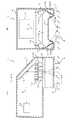
まず図1は、第1実施形態の二次元コード読取装置1の構成を表す構造図であり、(A)は、当該装置1の内部構造を側方から示し、(B)は、当該装置1の内部構造を(A)におけるX−X方向から示したものである。
【0025】
図1に示すように、本第1実施形態の二次元コード読取装置1は、読取対象物2に光を照射した際の反射光に基づいて、その読取対象物2の表面に印刷等で記録された二次元コード(例えばQRコード)を読み取るものであり、当該二次元コード読取装置1の装置本体4には、読取対象物2に向き合わされる開口である窓部6が空けられている。そして、その窓部6には、そこから装置本体4内へ塵が侵入することを防止するための透明カバー8が取り付けられている。
【0026】
そして更に、装置本体4内における窓部6の両脇付近には、透明カバー8を通して読取対象物2へ光を照射するために、複数個(本実施形態では5個)のLED10からなる2組のLED群12a,12bが夫々配置されている。
尚、両LED群12a,12bを成す各LED10は、窓部6の平面方向に対して垂直な方向(図1における下方)に光を出力するように、窓部6の平面方向と平行に保持された1枚の回路基板14上に、窓部6側を向けて垂直に実装されている。
【0027】
また、装置本体4内における窓部6の奥には、両LED群12a,12bの各LED10が発光した時に透明カバー8を通って装置本体4内へ入射してくる読取対象物2からの反射光hを、装置本体4の内部後方(図1(A)における左側)へ反射させる撮影用ミラー16が設けられており、更に、装置本体4の内部における後方(図1(A)における左側)には、撮影用ミラー16によって反射された読取対象物2からの反射光hを受けて、その読取対象物2上の画像を表す画像情報を取り込む二次元画像センサとしてのCCDエリアイメージセンサ(以下、CCDカメラという)18が設けられている。そして、本実施形態の二次元コード読取装置1では、CCDカメラ18に取り込まれた画像情報を、マイクロコンピュータ等の情報処理部(図示省略)によって処理することにより、読取対象物2に記録されていた二次元コードを解読する。
【0028】
ここで、窓部6に設けられた透明カバー8は、図1(B)に示すように、窓部6の平面方向に対して60度の傾斜角度を持つと共に、装置本体4における窓部6の側縁から装置本体4の内部側へと入り込んだ一対の光照射用平面部20a,20bと、窓部6の平面方向と平行であると共に、上記一対の光照射用平面部20a,20bの側縁のうちで装置本体4の内部側の側縁同士を結ぶ光入射用平面部22と、上記各光照射用平面部20a,20bの光入射用平面部22とは反対側の側縁(即ち、窓部6の側縁に当接する方の側縁)から、装置本体4の内部側へ、光照射用平面部20a,20bに対して60度の角度で伸びた一対の折り返し平面部24a,24bとを有している。
【0029】
換言すれば、窓部6の平面方向と平行な光入射用平面部22の一対の各側縁から、装置本体4の外部方向へ向けて、その光入射用平面部22との角度が120度となるように、一対の光照射用平面部20a,20bが伸びており、更に、その各光照射用平面部20a,20bの先端の側縁からは、装置本体4の内部方向へ向けて、その光照射用平面部20a,20bとの角度が60度となるように、一対の折り返し平面部24a,24bが伸びている。
【0030】
そして、透明カバー8の各折り返し平面部24a,24bの内側面(図1(B)における上側の表面)には、夫々、LED群12a,12bの各LED10から出力される光を反射して読取対象物2へ斜めに照射するための光照射用ミラー26a,26bが形成されている。
【0031】
一方、LED群12a,12bを実装する回路基板14は、装置本体4を図1(A)の下方から表す図2に示すように、読取対象物2からの反射光hが撮影用ミラー16へ到達するのを妨げないように、その平面形状が「コ」の字状に形成されている。
【0032】
尚、本実施形態では、LED群12a及び光照射用ミラー26aと、LED群12b及び光照射用ミラー26bとが、一対の光照射手段に相当している。
このように構成された本実施形態の二次元コード読取装置1では、LED群12a,12b(詳しくは、それを構成する各LED10)が発光すると、その光は、図1(B)の一点鎖線で示すように、透明カバー8の一対の折り返し平面部24a,24bに形成された光照射用ミラー26a,26bにより反射される。
【0033】
そして、光照射用ミラー26a,26bの各々によって反射された光は、透明カバー8の光照射用平面部20a,20bに垂直に進入し、その光照射用平面部20a,20bを通過した後、読取対象物2へ約60度の入射角で照射される。つまり、光照射用ミラー26a,26bで反射されて光照射用平面部20a,20bから外部へ出る光の光軸と、窓部6に対向される読取対象物2との角度は、約30度となる。
【0034】
すると、読取対象物2からの反射光(乱反射光)hが、透明カバー8の光入射用平面部22を通って装置本体4内に入射する。そして、その読取対象物2からの反射光hは、撮影用ミラー16によってCCDカメラ18へと反射され、このCCDカメラ18が、上記反射光hから読取対象物2上の画像を表す画像情報を取り込む。そして、その後は、前述したように、マイクロコンピュータ等の情報処理部が、CCDカメラ18に取り込まれた画像情報から、読取対象物2に記録されていた二次元コードを解読する。
【0035】
以上のような本第1実施形態の二次元コード読取装置1では、窓部6の両脇付近に夫々設けたLED群12a,12bからの光を読取対象物2に直接照射するのではなく、LED群12a,12bは、窓部6の平面方向に対して垂直の方向(即ち、読取対象物2の表面に対して垂直な方向)に光を出力し、その光を、光照射用ミラー26a,26bで反射させて、読取対象物2へ斜めに照射するようにしている。
【0036】
このため、窓部6の両脇付近に夫々設けられるLED群12a,12bは、窓部6の平面方向に対して垂直に配置すれば良く、この結果、図1及び図2に示したように、両LED群12a,12bを実装するための回路基板14として、1枚の共通な平面基板を使用することができる。よって、当該装置1の部品点数を少なくすることができると共に、組立性が良好となる。
【0037】
また、LED群12a,12bから出力される光を、光照射用ミラー26a,26bで反射させて、読取対象物2へ斜めに照射するようにしているため、両LED群12a,12b同士の離間距離を小さくしても、読取対象物2に対して光を一律に照射することができ、この結果、装置本体4の横幅寸法(図1(B)における左右方向の寸法)を小さくすることができる。
【0038】
そして更に、本第1実施形態の二次元コード読取装置1では、各光照射用ミラー26a,26bからの反射光が、透明カバー8の光照射用平面部20a,20bに垂直に進入して読取対象物2へ到達し、その読取対象物2からの反射光hが、透明カバー8の光入射用平面部22を通って装置本体4内に入射する構成であるため、読取対象物2へ光を照射する際に、透明カバー8で光量が損失してしまうことが無い。
【0039】
このように、本第1実施形態の二次元コード読取装置1によれば、LED群12a,12bから出力される光を読取対象物2に対して損失無く照射することができると共に、部品点数の増加と組立性の悪化を防止することができ、しかも、装置本体4をコンパクトなものにすることができる。
【0040】
また更に、本第1実施形態の二次元コード読取装置1では、LED群12a,12bの各々と共に一対の光照射手段を成す各光照射用ミラー26a,26bを、透明カバー8の折り返し平面部24a,24bにおける内側面に形成することにより、その光照射用ミラー26a,26bと透明カバー8とを一体化させている。このため、当該装置1を構成する部品点数をより少なくすることができると共に、組立性を一層良好なものにすることができる。
【0041】
ところで、上記第1実施形態の二次元コード読取装置1において、光照射用ミラー26a,26bとしては、表面が光沢鏡面であるのものを使用することができる。そして、この場合、LED10からの光を、読取対象物2へと効率的に反射させることができる。
【0042】
しかし、光照射用ミラー26a,26bとして、表面が光沢鏡面であるのものを用いた場合、LED10の像が読み取り面(読取対象物2の面)に現れて、読取対象物2への照度のムラが生じてしまうこともある。
そこで、光照射用ミラー26a,26bとして、表面が拡散反射面である拡散反射鏡を用いれば、LED10の光が拡散されて反射されることとなるため、読み取り面にLED10の像が現れて照度のムラが生じてしまうことを、確実に防止することができる。
【0043】
但し、光照射用ミラー26a,26bの表面を拡散反射面にすると、LED10からの光が拡散反射されるため、読み取り面に到達する光量が減少すると共に、視野周辺(即ち、窓部6の周辺)の照度も落ち込む傾向となる。
そこで次に、この問題を解決可能な第2実施形態の二次元コード読取装置について、図3を用いて説明する。尚、図3において、第1実施形態の二次元コード読取装置1と同じ部材については、同一の符号を付しているため、説明は省略する。また、当然であるが、本第2実施形態において、光照射用ミラー26a,26bの表面は、拡散反射面となっている。
【0044】
図3(A),(B)に示すように、第2実施形態の二次元コード読取装置30は、第1実施形態の二次元コード読取装置1と比較すると、光照射用ミラー26a,26bの各々に対向した一対の副反射ミラー32a,32bを追加して備えている。尚、図3(A)は、本第2実施形態の二次元コード読取装置30の内部構造を図1(B)と同じ方向から示したものであり、図3(B)は、副反射ミラー32a,32bの設置状態を模式的に表したものである。
【0045】
ここで、副反射ミラー32a,32bの設置状態について説明すると、図3(B)に示すように、本第2実施形態の二次元コード読取装置30は、装置本体4内にて撮影用ミラー16やCCDカメラ18等を収容するホルダ33を備えており、そのホルダ33の窓部6側の端部(図3(B)における下側の端部)には、各光照射用ミラー26a,26bとほぼ平行な斜面部34a,34bが設けられている。
【0046】
そして、各副反射ミラー32a,32bは、上記斜面部34a,34bにて、光照射用ミラー26a,26bと対向する側の面に設けられている。尚、各副反射ミラー32a,32bは、表面が光沢鏡面のものであり、本実施形態では、上記斜面部34a,34bに貼付された光沢ステッカである。
【0047】
このような本第2実施形態の二次元コード読取装置30によれば、光照射用ミラー26a,26bによって装置本体4側へ拡散反射された光をも、副反射ミラー32a,32bによって、光照射用ミラー26a,26bへ再び戻すことができる。
【0048】
つまり、光照射用ミラー26a,26bで装置本体4側へ拡散反射された光は、副反射ミラー32a,32bによって、一部は読取対象物2へと直接照射され、また、大部分は光照射用ミラー26a,26bに戻された後、読取対象物2に照射されることとなるからである。
【0049】
次に、本発明者が行った実験結果を図4及び図5に示す。
図4及び図5は、窓部6に向き合わされた平面での受光量(換言すれば、その平面への照度)の測定結果を表す三次元等高線グラフであり、x軸とy軸とが、受光量を測定した平面領域であって、窓部6よりも若干大きい領域を表し、z軸が、受光量の大きさ(照度)を表している。そして、図4は、第1実施形態の二次元コード読取装置1において、光照射用ミラー26a,26bの表面を拡散反射面にした場合(つまり、第2実施形態の二次元コード読取装置30において、副反射ミラー32a,32bを設けなかった場合)を表しており、図5は、第2実施形態の二次元コード読取装置30の場合を表している。
【0050】
図4と図5との比較から分かるように、光照射用ミラー26a,26bの表面を拡散反射面にしただけの場合には、読み取り面に到達する光量が全体的に減少すると共に、視野周辺の照度も落ち込んでしまう。これに対して、副反射ミラー32a,32bを設けた第2実施形態の二次元コード読取装置30によれば、読み取り面に到達する光量を全体的に増大させることができると共に、視野周辺の照度の落ち込みも抑制することができる。
【0051】
このため、第2実施形態の二次元コード読取装置30によれば、読取対象物2への照射光をほぼ均一にしつつ、十分な照度を得ることができるようになる。
以上、本発明の一実施形態について説明したが、本発明は、上記各実施形態に限定されるものではなく、種々の形態を採り得ることは言うまでもない。
【0052】
例えば、透明カバー8における光入射用平面部22と光照射用平面部20a,20bとが成す角度、及び光照射用平面部20a,20bと折り返し平面部24a,24bとが成す角度は、前述した角度に限るものではなく、読取対象物2に対する光の照射角度に応じて適宜設定すれば良い。
【0053】
一方、LED群12a,12bを構成するLED10の数は、5個に限らず、例えば7個やそれ以外の数でも良い。
また、上記実施形態の二次元コード読取装置1,30では、LED群12a,12bを構成する複数のLED10が、一列に並べられていたが、LED10は、例えばジグザグに並べるようにしても良い。
【0054】
また更に、上記実施形態の二次元コード読取装置1,30において、CCDカメラ18の代わりに、CMOSエリアイメージセンサといった他の二次元画像センサを用いても良い。
【図面の簡単な説明】
【図1】第1実施形態の二次元コード読取装置の構成を表す構造図である。
【図2】LED群を実装する回路基板の形状を説明する説明図である。
【図3】第2実施形態の二次元コード読取装置の構成を表す構造図である。
【図4】光照射用ミラーの表面を拡散反射面にすると共に、副反射ミラーを設けない場合の、照度の測定結果を表す三次元等高線グラフである。
【図5】副反射ミラーを設けた第2実施形態の場合の、照度の測定結果を表す三次元等高線グラフである。
【図6】従来の二次元コード読取装置の構成及び問題点を説明する説明図である。
【符号の説明】
1,30…二次元コード読取装置 2…読取対象物 4…装置本体
6…窓部 8…透明カバー 10…LED(発光ダイオード)
12a,12b…LED群 14…回路基板 16…撮影用ミラー
18…CCDカメラ 20a,20b…光照射用平面部
22…光入射用平面部 24a,24b…折り返し平面部
26a,26b…光照射用ミラー 32a,32b…副反射ミラー
33…ホルダ 34a,34b…斜面部[0001]
TECHNICAL FIELD OF THE INVENTION
The present invention relates to a two-dimensional code reader that reads a two-dimensional code recorded on the surface of a reading target based on reflected light when the reading target is irradiated with light.
[0002]
[Prior art]
2. Description of the Related Art Conventionally, as shown in FIG. 6, a two-dimensional code reader of this type has a
[0003]
The two-dimensional code reader of this type transmits reflected light h from the object to be read 102 that enters the apparatus
[0004]
FIG. 6 shows an example of a configuration in which the two-dimensional image sensor 110 directly receives the reflected light h from the
[0005]
By the way, in this type of two-dimensional code reader, the reason why light is obliquely applied to the object to be read 102 is to prevent the influence of specular reflection on the object to be read 102. Specifically, when the directly reflected light from the reading object 102 (reflected light having the same reflection angle as the incident angle of the light on the reading object 102) enters the two-dimensional image sensor 110, the two-dimensional image This is because the sensor 110 recognizes the location as a point having high luminance, similarly to the human eyes, so that the two-dimensional code on the
[0006]
Therefore, in the conventional two-dimensional code reader, as shown in FIG. 6, the LEDs 108a and 108b are arranged not to be perpendicular to the plane direction of the
[0007]
[Problems to be solved by the invention]
However, the conventional two-dimensional code reader has the following problems.
First, as a first problem, in the conventional device, light output from the LEDs 108a and 108b as light-emitting elements obliquely enters the dustproof
[0008]
As a second problem, in the conventional device, as described above, the LEDs 108a and 108b are arranged obliquely with respect to the plane direction of the
[0009]
Some circuit boards have a flexibility called a flexible board, but such a flexible board is more costly than a general non-flexible circuit board such as a glass epoxy board or a paper phenol board. When a flexible substrate is used, a special structure and parts for holding the flexible substrate in the apparatus
[0010]
As a third problem, in order to uniformly irradiate the
[0011]
The present invention has been made in view of the above-described problems, and can irradiate light output from a light emitting element to a reading target without loss, increasing the number of parts and deteriorating assemblability. It is another object of the present invention to provide a compact two-dimensional code reader that can prevent the occurrence of the two-dimensional code.
[0012]
Means for Solving the Problems and Effects of the Invention
The two-dimensional code reading device according to the present invention according to
[0013]
Then, the two-dimensional code reading device, based on the reflected light from the object to be read that enters the apparatus body through the transparent cover due to the light irradiation by the pair of light irradiation means, detects the object to be read. Read the two-dimensional code recorded on the surface.
Here, in particular, in the two-dimensional code reading device of the present invention, each of the pair of light irradiating means includes a light emitting element that outputs light in a direction perpendicular to a plane direction of the window, and an output light from the light emitting element. And a light irradiating mirror that irradiates the object to be read obliquely by reflecting the reflected light.
[0014]
Further, in the two-dimensional code reader of the present invention, the dust-proof transparent cover provided on the window portion has a window portion so that the reflected light from each of the light irradiation mirrors enters and passes vertically. A pair of light irradiating flat parts having a predetermined inclination angle with respect to the plane direction, and a pair of light irradiating flat parts parallel to the plane direction of the window and inside the apparatus main body among side edges of the pair of light irradiating flat parts. And a light incident flat surface portion connecting the side edges of the side.
[0015]
That is, in the two-dimensional code reader of the present invention, the light emitting elements are provided near both sides of the window, respectively, as in the conventional apparatus, but the light from the light emitting elements is directly irradiated on the object to be read. Instead, the light emitting element outputs light in a direction perpendicular to the plane direction of the window (that is, in a direction perpendicular to the surface of the object to be read), and reflects the light with the light irradiating mirror. Thus, the object to be read is irradiated obliquely.
[0016]
For this reason, the light emitting elements provided respectively near both sides of the window may be arranged perpendicular to the plane direction of the window. As a result, one light emitting element is mounted as a circuit board for mounting each light emitting element. Can be used. Therefore, the number of parts can be reduced, and the assemblability is improved.
[0017]
Further, light output from the light emitting element in a direction perpendicular to the plane direction of the window is reflected by the light irradiating mirror to irradiate the object to be read obliquely. Even if the separation distance is reduced, light can be uniformly applied to the object to be read, and as a result, the width of the apparatus main body (the size of the window in the plane direction) can be reduced.
[0018]
Further, in the two-dimensional code reader of the present invention, the reflected light from each light irradiating mirror enters the light irradiating flat portion of the transparent cover perpendicularly, reaches the reading object, and from the reading object. Reflected light enters the apparatus main body through the light incident flat portion of the transparent cover, so that when irradiating the reading target with light, the light amount is not lost by the transparent cover. .
[0019]
As described above, according to the two-dimensional code reader of the present invention, it is possible to irradiate the light output from the light emitting element to the object to be read without loss, and to prevent an increase in the number of parts and deterioration in assemblability. In addition, the apparatus main body can be made compact.
[0020]
By the way, it is more effective if the respective light irradiating mirrors forming a pair of light irradiating means are integrated with the dustproof transparent cover as described in
That is, in the two-dimensional code reader according to the second aspect, the transparent cover extends at a predetermined angle from the side edge of each light irradiation plane portion opposite to the light incidence plane portion to the inside of the apparatus main body. And each of the light-irradiating mirrors is formed on the inner surface of each of the folded plane portions, respectively, so as to be integrated with the transparent cover.
[0021]
According to the two-dimensional code reader according to the second aspect, the number of parts can be further reduced, and the assemblability is further improved.
On the other hand, in the two-dimensional code reading device of the present invention, as each light irradiating mirror, a mirror whose surface (light reflecting surface) is a glossy mirror surface can be used. When an LED or the like having a high directivity is used, an image of the light emitting element appears on a reading surface, and unevenness of illuminance on a reading target object occurs. Note that the reading surface is a surface on which the window of the present apparatus faces, and is a surface of a reading target when the present apparatus is used.
[0022]
Therefore, if the surface of each light irradiating mirror is made to be a diffuse reflection surface that diffuses and reflects light from the light emitting element, an image of the light emitting element appears on the reading surface and uneven illuminance is caused. Can be prevented from occurring.
However, when the surface of the light irradiating mirror is a diffuse reflection surface, the amount of light reaching the reading surface decreases, and the illuminance around the visual field (that is, around the window) tends to decrease.
[0023]
Therefore, if a sub-reflection mirror for irradiating the object to be read with the reflected light of each light irradiating mirror is further provided so as to be opposed to each light irradiating mirror as described in
[0024]
BEST MODE FOR CARRYING OUT THE INVENTION
Hereinafter, a two-dimensional code reader according to an embodiment to which the present invention is applied will be described with reference to the drawings.
First, FIG. 1 is a structural diagram showing a configuration of a two-dimensional
[0025]
As shown in FIG. 1, a two-
[0026]
Further, two sets of plural (five in this embodiment)
The
[0027]
Further, behind the
[0028]
Here, as shown in FIG. 1B, the
[0029]
In other words, the angle between the pair of side edges of the light incident
[0030]
Then, the light output from each
[0031]
On the other hand, the circuit board 14 on which the LED groups 12a and 12b are mounted, as shown in FIG. 2 showing the device
[0032]
In the present embodiment, the LED group 12a and the light irradiating mirror 26a and the LED group 12b and the light irradiating mirror 26b correspond to a pair of light irradiating means.
In the two-
[0033]
The light reflected by each of the light irradiating mirrors 26a and 26b vertically enters the light irradiating
[0034]
Then, the reflected light (irregularly reflected light) h from the
[0035]
In the two-
[0036]
Therefore, the LED groups 12a and 12b provided near both sides of the
[0037]
In addition, since the light output from the LED groups 12a and 12b is reflected by the light irradiating mirrors 26a and 26b to irradiate the
[0038]
Further, in the two-
[0039]
As described above, according to the two-
[0040]
Furthermore, in the two-dimensional
[0041]
By the way, in the two-
[0042]
However, when the mirrors for light irradiation 26a and 26b have glossy mirror surfaces, the image of the
Therefore, if the light reflecting mirrors 26a and 26b are diffuse reflecting mirrors whose surfaces are diffuse reflecting surfaces, the light of the
[0043]
However, if the surfaces of the light irradiating mirrors 26a and 26b are diffuse reflection surfaces, the light from the
Next, a two-dimensional code reader according to a second embodiment capable of solving this problem will be described with reference to FIG. Note that, in FIG. 3, the same members as those of the two-dimensional
[0044]
As shown in FIGS. 3A and 3B, the two-
[0045]
Here, the installation state of the sub-reflection mirrors 32a and 32b will be described. As shown in FIG. 3B, the two-
[0046]
The sub-reflection mirrors 32a and 32b are provided on the surfaces of the slopes 34a and 34b on the side facing the light irradiation mirrors 26a and 26b. Each of the sub-reflection mirrors 32a and 32b has a glossy mirror surface, and in this embodiment, is a glossy sticker attached to the slope portions 34a and 34b.
[0047]
According to the two-
[0048]
That is, the light diffused and reflected by the light irradiating mirrors 26a and 26b toward the
[0049]
Next, FIGS. 4 and 5 show the results of experiments performed by the inventor.
4 and 5 are three-dimensional contour graphs showing the measurement results of the amount of received light (in other words, the illuminance on the plane) on the plane facing the
[0050]
As can be seen from a comparison between FIG. 4 and FIG. 5, when the surfaces of the light irradiating mirrors 26a and 26b are merely diffuse reflection surfaces, the amount of light reaching the reading surface is reduced as a whole, and The illuminance also drops. On the other hand, according to the two-
[0051]
For this reason, according to the two-dimensional
As mentioned above, although one Embodiment of this invention was described, it cannot be overemphasized that this invention is not limited to said each embodiment, and can take various forms.
[0052]
For example, the angle formed by the light
[0053]
On the other hand, the number of
Further, in the two-
[0054]
Further, in the two-
[Brief description of the drawings]
FIG. 1 is a structural diagram illustrating a configuration of a two-dimensional code reader according to a first embodiment.
FIG. 2 is an explanatory diagram illustrating a shape of a circuit board on which an LED group is mounted.
FIG. 3 is a structural diagram illustrating a configuration of a two-dimensional code reader according to a second embodiment.
FIG. 4 is a three-dimensional contour graph showing illuminance measurement results when the surface of the light irradiation mirror is a diffuse reflection surface and no sub-reflection mirror is provided.
FIG. 5 is a three-dimensional contour graph showing a measurement result of illuminance in the case of the second embodiment in which a sub-reflection mirror is provided.
FIG. 6 is an explanatory diagram illustrating the configuration and problems of a conventional two-dimensional code reading device.
[Explanation of symbols]
1, 30: two-dimensional code reading device 2: reading object 4: device body
6 ...
12a, 12b LED group 14
18:
22: Light incident plane part 24a, 24b: Turned plane part
26a, 26b:
33: Holder 34a, 34b: Slope
Claims (4)
Translated fromJapanese前記窓部に設けられて、該窓部から前記装置本体内へ塵が侵入することを防止する透明カバーと、
前記装置本体内における前記窓部の両脇付近に夫々設けられ、該窓部の前記透明カバーを通して前記読取対象物へ斜めに光を照射する一対の光照射手段と、
を備え、前記一対の光照射手段による光の照射に伴い前記透明カバーを通って装置本体内に入射してくる前記読取対象物からの反射光に基づいて、前記読取対象物の表面に記録された二次元コードを読み取る二次元コード読取装置において、
前記一対の光照射手段の各々は、
前記窓部の平面方向に対して垂直の方向に光を出力する発光素子と、
該発光素子から出力される光を反射して前記読取対象物へ斜めに照射する光照射用ミラーとからなり、
前記透明カバーは、
前記各光照射用ミラーからの反射光が夫々垂直に進入して通過するように、前記窓部の平面方向に対して所定の傾斜角度を持った一対の光照射用平面部と、
前記窓部の平面方向と平行であると共に、前記一対の光照射用平面部の側縁のうちで前記装置本体の内部側の側縁同士を結ぶ光入射用平面部とを有していること、
を特徴とする二次元コード読取装置。An apparatus main body having a window portion facing a reading target having a two-dimensional code recorded on its surface,
A transparent cover provided on the window to prevent dust from entering the device body from the window;
A pair of light irradiating means that are respectively provided near both sides of the window in the apparatus main body, and irradiate light obliquely to the object to be read through the transparent cover of the window,
The light is recorded on the surface of the object to be read based on the reflected light from the object to be read that enters the apparatus main body through the transparent cover with light irradiation by the pair of light irradiation units. In a two-dimensional code reader that reads a two-dimensional code,
Each of the pair of light irradiation means,
A light-emitting element that outputs light in a direction perpendicular to the plane direction of the window portion,
A light irradiation mirror that reflects light output from the light emitting element and irradiates the object to be read obliquely,
The transparent cover,
A pair of light irradiation plane portions having a predetermined inclination angle with respect to the plane direction of the window portion, so that the reflected light from each of the light irradiation mirrors enters and passes vertically.
A plane parallel to the plane direction of the window, and a light incident plane connecting the side edges on the inner side of the apparatus main body among the side edges of the pair of light irradiation planes. ,
A two-dimensional code reader.
前記透明カバーは、
前記各光照射用平面部の前記光入射用平面部とは反対側の側縁から前記装置本体の内部側へ所定の角度で伸びた一対の折り返し平面部を有し、
前記各光照射用ミラーは、前記各折り返し平面部の内側面に夫々形成されることにより、前記透明カバーと一体化されていること、
を特徴とする二次元コード読取装置。The two-dimensional code reader according to claim 1,
The transparent cover,
Each of the light irradiation flat portions has a pair of folded flat portions extending at a predetermined angle from a side edge opposite to the light incident flat portion to the inside of the device main body,
Each of the light irradiation mirrors is formed on the inner surface of each of the folded flat portions, thereby being integrated with the transparent cover,
A two-dimensional code reader.
前記各光照射用ミラーの表面が、拡散反射面であること、
を特徴とする二次元コード読取装置。The two-dimensional code reader according to claim 1 or 2,
The surface of each light irradiation mirror is a diffuse reflection surface,
A two-dimensional code reader.
前記各光照射用ミラーの反射光を前記読取対象物に照射するための副反射ミラーを、前記各光照射用ミラーに対向させて夫々設けたこと、
を特徴とする二次元コード読取装置。The two-dimensional code reader according to claim 3,
A sub-reflection mirror for irradiating the reading target with the reflected light of each of the light irradiation mirrors is provided to face each of the light irradiation mirrors, respectively.
A two-dimensional code reader.
Priority Applications (1)
| Application Number | Priority Date | Filing Date | Title |
|---|---|---|---|
| JP2000141738AJP3593950B2 (en) | 1999-05-26 | 2000-05-15 | 2D code reader |
Applications Claiming Priority (3)
| Application Number | Priority Date | Filing Date | Title |
|---|---|---|---|
| JP11-146652 | 1999-05-26 | ||
| JP14665299 | 1999-05-26 | ||
| JP2000141738AJP3593950B2 (en) | 1999-05-26 | 2000-05-15 | 2D code reader |
Publications (2)
| Publication Number | Publication Date |
|---|---|
| JP2001043301A JP2001043301A (en) | 2001-02-16 |
| JP3593950B2true JP3593950B2 (en) | 2004-11-24 |
Family
ID=26477444
Family Applications (1)
| Application Number | Title | Priority Date | Filing Date |
|---|---|---|---|
| JP2000141738AExpired - Fee RelatedJP3593950B2 (en) | 1999-05-26 | 2000-05-15 | 2D code reader |
Country Status (1)
| Country | Link |
|---|---|
| JP (1) | JP3593950B2 (en) |
Families Citing this family (23)
| Publication number | Priority date | Publication date | Assignee | Title |
|---|---|---|---|---|
| DE60126782T2 (en) | 2000-08-10 | 2007-12-06 | Novo Nordisk A/S | DEVICE FOR ADMINISTERING MEDICAMENTS WITH A CASSETTE HOLDER |
| US6994261B2 (en) | 2000-08-10 | 2006-02-07 | Novo Nirdisk A/S | Support for a cartridge for transferring an electronically readable item of information from the cartridge to an electronic circuit |
| WO2004084795A1 (en) | 2003-03-24 | 2004-10-07 | Novo Nordisk A/S | Transparent electronic marking of a medication cartridge |
| US9536124B1 (en) | 2003-10-24 | 2017-01-03 | Cognex Corporation | Integrated illumination assembly for symbology reader |
| US9070031B2 (en) | 2003-10-24 | 2015-06-30 | Cognex Technology And Investment Llc | Integrated illumination assembly for symbology reader |
| US7604174B2 (en) | 2003-10-24 | 2009-10-20 | Cognex Technology And Investment Corporation | Method and apparatus for providing omnidirectional lighting in a scanning device |
| US7823783B2 (en) | 2003-10-24 | 2010-11-02 | Cognex Technology And Investment Corporation | Light pipe illumination system and method |
| US7874487B2 (en)* | 2005-10-24 | 2011-01-25 | Cognex Technology And Investment Corporation | Integrated illumination assembly for symbology reader |
| US7823789B2 (en) | 2004-12-21 | 2010-11-02 | Cognex Technology And Investment Corporation | Low profile illumination for direct part mark readers |
| WO2005114546A1 (en)* | 2004-05-24 | 2005-12-01 | Kenji Yoshida | Dot pattern reading unit and mouse comprising it |
| US7617984B2 (en) | 2004-12-16 | 2009-11-17 | Cognex Technology And Investment Corporation | Hand held symbology reader illumination diffuser |
| US9292724B1 (en) | 2004-12-16 | 2016-03-22 | Cognex Corporation | Hand held symbology reader illumination diffuser with aimer optics |
| WO2006120182A1 (en) | 2005-05-10 | 2006-11-16 | Novo Nordisk A/S | Injection device comprising an optical sensor |
| EP1929248B1 (en) | 2005-09-22 | 2015-11-11 | Novo Nordisk A/S | Device and method for contact free absolute position determination |
| EP1999691B1 (en) | 2006-03-20 | 2010-08-18 | Novo Nordisk A/S | Contact free reading of cartridge identification codes |
| CN101421913B (en) | 2006-04-12 | 2012-07-18 | 诺沃-诺迪斯克有限公司 | Determination of the absolute position of movable mounted elements in drug delivery devices |
| BRPI0710915A2 (en) | 2006-04-26 | 2011-09-27 | Novo Nordisk As | medication delivery device and method for determining absolute positions of a first member relative to a second member of a medication delivery device |
| KR100763883B1 (en)* | 2006-05-26 | 2007-10-05 | 주식회사 더존씨앤티 | Handheld scanner |
| EP2125083B1 (en) | 2007-03-21 | 2013-08-21 | Novo Nordisk A/S | A medical delivery system having container recognition and container for use with the medical delivery system |
| WO2010092156A1 (en) | 2009-02-13 | 2010-08-19 | Novo Nordisk A/S | Medical device and cartridge |
| CN107898174B (en)* | 2017-11-26 | 2023-06-27 | 国家电网公司 | Two-dimension code data archiving device |
| DE102018103544B3 (en) | 2018-02-16 | 2018-10-18 | Sick Ag | Camera and method for capturing image data |
| KR102402344B1 (en)* | 2018-12-26 | 2022-05-30 | 웨이모 엘엘씨 | Proximity lighting module |
- 2000
- 2000-05-15JPJP2000141738Apatent/JP3593950B2/ennot_activeExpired - Fee Related
Also Published As
| Publication number | Publication date |
|---|---|
| JP2001043301A (en) | 2001-02-16 |
Similar Documents
| Publication | Publication Date | Title |
|---|---|---|
| JP3593950B2 (en) | 2D code reader | |
| US5541419A (en) | Symbology reader wth reduced specular reflection | |
| US9332148B2 (en) | Reading device | |
| US5585615A (en) | Image reading apparatus | |
| US20190166278A1 (en) | Information reading device | |
| JP5185756B2 (en) | Substrate detection apparatus and method | |
| CN101271246B (en) | image capture equipment | |
| EP0610504A1 (en) | Information reading apparatus | |
| US6612730B1 (en) | Rod-shaped light guide and illuminating device incorporating rod-shaped light guide | |
| US20120113483A1 (en) | Booklet reading device | |
| JP2000194829A (en) | Uneven pattern reader | |
| JP2020182165A (en) | Image reader | |
| US20090059616A1 (en) | Illumination light assembly with self-retaining lightpipe for minimizing specular reflection in electro-optical reader | |
| KR101011292B1 (en) | Compact imager with transparent window and illuminator | |
| KR100326913B1 (en) | Image pickup unit | |
| JP7560149B2 (en) | Illumination device and imaging system | |
| JPH05314296A (en) | Reader for two-dimensional code or the like | |
| JP4103445B2 (en) | Hand-held optical information reader | |
| JP7023383B2 (en) | Image reader | |
| JP4230210B2 (en) | Optical reader | |
| JP3846943B2 (en) | Paper sheet reader | |
| JP7089886B2 (en) | Identification device | |
| JP2007172547A (en) | Engraved mark reader | |
| JP2025119546A (en) | scanner | |
| JP5126640B2 (en) | Imaging device |
Legal Events
| Date | Code | Title | Description |
|---|---|---|---|
| A977 | Report on retrieval | Free format text:JAPANESE INTERMEDIATE CODE: A971007 Effective date:20040714 | |
| TRDD | Decision of grant or rejection written | ||
| A01 | Written decision to grant a patent or to grant a registration (utility model) | Free format text:JAPANESE INTERMEDIATE CODE: A01 Effective date:20040810 | |
| A61 | First payment of annual fees (during grant procedure) | Free format text:JAPANESE INTERMEDIATE CODE: A61 Effective date:20040823 | |
| R150 | Certificate of patent or registration of utility model | Free format text:JAPANESE INTERMEDIATE CODE: R150 | |
| FPAY | Renewal fee payment (event date is renewal date of database) | Free format text:PAYMENT UNTIL: 20100910 Year of fee payment:6 | |
| FPAY | Renewal fee payment (event date is renewal date of database) | Free format text:PAYMENT UNTIL: 20100910 Year of fee payment:6 | |
| FPAY | Renewal fee payment (event date is renewal date of database) | Free format text:PAYMENT UNTIL: 20110910 Year of fee payment:7 | |
| FPAY | Renewal fee payment (event date is renewal date of database) | Free format text:PAYMENT UNTIL: 20120910 Year of fee payment:8 | |
| FPAY | Renewal fee payment (event date is renewal date of database) | Free format text:PAYMENT UNTIL: 20120910 Year of fee payment:8 | |
| FPAY | Renewal fee payment (event date is renewal date of database) | Free format text:PAYMENT UNTIL: 20120910 Year of fee payment:8 | |
| FPAY | Renewal fee payment (event date is renewal date of database) | Free format text:PAYMENT UNTIL: 20130910 Year of fee payment:9 | |
| R250 | Receipt of annual fees | Free format text:JAPANESE INTERMEDIATE CODE: R250 | |
| LAPS | Cancellation because of no payment of annual fees |