JP3593671B2 - Molding machine - Google Patents
Molding machineDownload PDFInfo
- Publication number
- JP3593671B2 JP3593671B2JP12222898AJP12222898AJP3593671B2JP 3593671 B2JP3593671 B2JP 3593671B2JP 12222898 AJP12222898 AJP 12222898AJP 12222898 AJP12222898 AJP 12222898AJP 3593671 B2JP3593671 B2JP 3593671B2
- Authority
- JP
- Japan
- Prior art keywords
- field
- molding machine
- movable body
- speed
- function unit
- Prior art date
- Legal status (The legal status is an assumption and is not a legal conclusion. Google has not performed a legal analysis and makes no representation as to the accuracy of the status listed.)
- Expired - Fee Related
Links
- 238000000465mouldingMethods0.000titleclaimsdescription44
- 238000001514detection methodMethods0.000claimsdescription48
- 238000010438heat treatmentMethods0.000claimsdescription19
- 239000011347resinSubstances0.000claimsdescription19
- 229920005989resinPolymers0.000claimsdescription19
- 238000001746injection mouldingMethods0.000claimsdescription18
- 238000004804windingMethods0.000description101
- 230000004907fluxEffects0.000description36
- 238000002347injectionMethods0.000description29
- 239000007924injectionSubstances0.000description29
- 230000002093peripheral effectEffects0.000description15
- 230000007246mechanismEffects0.000description14
- 238000010586diagramMethods0.000description7
- 238000000034methodMethods0.000description5
- 238000006243chemical reactionMethods0.000description4
- 230000007423decreaseEffects0.000description3
- 238000005259measurementMethods0.000description3
- 230000004048modificationEffects0.000description3
- 238000012986modificationMethods0.000description3
- 239000012778molding materialSubstances0.000description3
- XEEYBQQBJWHFJM-UHFFFAOYSA-NIronChemical compound[Fe]XEEYBQQBJWHFJM-UHFFFAOYSA-N0.000description2
- 230000000694effectsEffects0.000description2
- 238000007885magnetic separationMethods0.000description2
- 230000008569processEffects0.000description2
- 230000001360synchronised effectEffects0.000description2
- 229910001030Iron–nickel alloyInorganic materials0.000description1
- 230000008859changeEffects0.000description1
- 230000001419dependent effectEffects0.000description1
- 239000000428dustSubstances0.000description1
- 230000005684electric fieldEffects0.000description1
- 230000005284excitationEffects0.000description1
- 229910052742ironInorganic materials0.000description1
- 239000010410layerSubstances0.000description1
- 239000000463materialSubstances0.000description1
- 238000002844meltingMethods0.000description1
- 230000008018meltingEffects0.000description1
- 239000004014plasticizerSubstances0.000description1
- 230000009467reductionEffects0.000description1
- 230000004044responseEffects0.000description1
- 239000002356single layerSubstances0.000description1
- 238000005303weighingMethods0.000description1
- 229910000859α-FeInorganic materials0.000description1
Images


Classifications
- B—PERFORMING OPERATIONS; TRANSPORTING
- B29—WORKING OF PLASTICS; WORKING OF SUBSTANCES IN A PLASTIC STATE IN GENERAL
- B29C—SHAPING OR JOINING OF PLASTICS; SHAPING OF MATERIAL IN A PLASTIC STATE, NOT OTHERWISE PROVIDED FOR; AFTER-TREATMENT OF THE SHAPED PRODUCTS, e.g. REPAIRING
- B29C45/00—Injection moulding, i.e. forcing the required volume of moulding material through a nozzle into a closed mould; Apparatus therefor
- B29C45/17—Component parts, details or accessories; Auxiliary operations
- B29C45/46—Means for plasticising or homogenising the moulding material or forcing it into the mould
- B29C45/47—Means for plasticising or homogenising the moulding material or forcing it into the mould using screws
- B29C45/50—Axially movable screw
- B29C45/5008—Drive means therefor
- H—ELECTRICITY
- H02—GENERATION; CONVERSION OR DISTRIBUTION OF ELECTRIC POWER
- H02K—DYNAMO-ELECTRIC MACHINES
- H02K1/00—Details of the magnetic circuit
- H02K1/06—Details of the magnetic circuit characterised by the shape, form or construction
- H02K1/22—Rotating parts of the magnetic circuit
- H02K1/27—Rotor cores with permanent magnets
- H02K1/2706—Inner rotors
- H02K1/2713—Inner rotors the magnetisation axis of the magnets being axial, e.g. claw-pole type
- H—ELECTRICITY
- H02—GENERATION; CONVERSION OR DISTRIBUTION OF ELECTRIC POWER
- H02K—DYNAMO-ELECTRIC MACHINES
- H02K1/00—Details of the magnetic circuit
- H02K1/06—Details of the magnetic circuit characterised by the shape, form or construction
- H02K1/22—Rotating parts of the magnetic circuit
- H02K1/27—Rotor cores with permanent magnets
- H02K1/2793—Rotors axially facing stators
- H02K1/2795—Rotors axially facing stators the rotor consisting of two or more circumferentially positioned magnets
- H02K1/2796—Rotors axially facing stators the rotor consisting of two or more circumferentially positioned magnets where both axial sides of the rotor face a stator
- H—ELECTRICITY
- H02—GENERATION; CONVERSION OR DISTRIBUTION OF ELECTRIC POWER
- H02K—DYNAMO-ELECTRIC MACHINES
- H02K16/00—Machines with more than one rotor or stator
- H02K16/04—Machines with one rotor and two stators
- H—ELECTRICITY
- H02—GENERATION; CONVERSION OR DISTRIBUTION OF ELECTRIC POWER
- H02K—DYNAMO-ELECTRIC MACHINES
- H02K21/00—Synchronous motors having permanent magnets; Synchronous generators having permanent magnets
- H02K21/12—Synchronous motors having permanent magnets; Synchronous generators having permanent magnets with stationary armatures and rotating magnets
- H02K21/14—Synchronous motors having permanent magnets; Synchronous generators having permanent magnets with stationary armatures and rotating magnets with magnets rotating within the armatures
- H02K21/145—Synchronous motors having permanent magnets; Synchronous generators having permanent magnets with stationary armatures and rotating magnets with magnets rotating within the armatures having an annular armature coil
- H—ELECTRICITY
- H02—GENERATION; CONVERSION OR DISTRIBUTION OF ELECTRIC POWER
- H02K—DYNAMO-ELECTRIC MACHINES
- H02K21/00—Synchronous motors having permanent magnets; Synchronous generators having permanent magnets
- H02K21/12—Synchronous motors having permanent magnets; Synchronous generators having permanent magnets with stationary armatures and rotating magnets
- H02K21/22—Synchronous motors having permanent magnets; Synchronous generators having permanent magnets with stationary armatures and rotating magnets with magnets rotating around the armatures, e.g. flywheel magnetos
- H02K21/227—Synchronous motors having permanent magnets; Synchronous generators having permanent magnets with stationary armatures and rotating magnets with magnets rotating around the armatures, e.g. flywheel magnetos having an annular armature coil
- H—ELECTRICITY
- H02—GENERATION; CONVERSION OR DISTRIBUTION OF ELECTRIC POWER
- H02K—DYNAMO-ELECTRIC MACHINES
- H02K21/00—Synchronous motors having permanent magnets; Synchronous generators having permanent magnets
- H02K21/12—Synchronous motors having permanent magnets; Synchronous generators having permanent magnets with stationary armatures and rotating magnets
- H02K21/24—Synchronous motors having permanent magnets; Synchronous generators having permanent magnets with stationary armatures and rotating magnets with magnets axially facing the armatures, e.g. hub-type cycle dynamos
- B—PERFORMING OPERATIONS; TRANSPORTING
- B29—WORKING OF PLASTICS; WORKING OF SUBSTANCES IN A PLASTIC STATE IN GENERAL
- B29C—SHAPING OR JOINING OF PLASTICS; SHAPING OF MATERIAL IN A PLASTIC STATE, NOT OTHERWISE PROVIDED FOR; AFTER-TREATMENT OF THE SHAPED PRODUCTS, e.g. REPAIRING
- B29C45/00—Injection moulding, i.e. forcing the required volume of moulding material through a nozzle into a closed mould; Apparatus therefor
- B29C45/17—Component parts, details or accessories; Auxiliary operations
- B29C45/46—Means for plasticising or homogenising the moulding material or forcing it into the mould
- B29C45/47—Means for plasticising or homogenising the moulding material or forcing it into the mould using screws
- B29C45/50—Axially movable screw
- B29C45/5008—Drive means therefor
- B29C2045/5024—Drive means therefor screws rotated by the coaxial rotor of an electric motor
- B—PERFORMING OPERATIONS; TRANSPORTING
- B29—WORKING OF PLASTICS; WORKING OF SUBSTANCES IN A PLASTIC STATE IN GENERAL
- B29C—SHAPING OR JOINING OF PLASTICS; SHAPING OF MATERIAL IN A PLASTIC STATE, NOT OTHERWISE PROVIDED FOR; AFTER-TREATMENT OF THE SHAPED PRODUCTS, e.g. REPAIRING
- B29C45/00—Injection moulding, i.e. forcing the required volume of moulding material through a nozzle into a closed mould; Apparatus therefor
- B29C45/17—Component parts, details or accessories; Auxiliary operations
- B29C45/46—Means for plasticising or homogenising the moulding material or forcing it into the mould
- B29C45/47—Means for plasticising or homogenising the moulding material or forcing it into the mould using screws
- B29C45/50—Axially movable screw
- B29C45/5008—Drive means therefor
- B29C2045/5032—Drive means therefor using means for detecting injection or back pressures
- B—PERFORMING OPERATIONS; TRANSPORTING
- B29—WORKING OF PLASTICS; WORKING OF SUBSTANCES IN A PLASTIC STATE IN GENERAL
- B29C—SHAPING OR JOINING OF PLASTICS; SHAPING OF MATERIAL IN A PLASTIC STATE, NOT OTHERWISE PROVIDED FOR; AFTER-TREATMENT OF THE SHAPED PRODUCTS, e.g. REPAIRING
- B29C45/00—Injection moulding, i.e. forcing the required volume of moulding material through a nozzle into a closed mould; Apparatus therefor
- B29C45/17—Component parts, details or accessories; Auxiliary operations
- B29C45/46—Means for plasticising or homogenising the moulding material or forcing it into the mould
- B29C45/47—Means for plasticising or homogenising the moulding material or forcing it into the mould using screws
- B29C45/50—Axially movable screw
- B29C45/5008—Drive means therefor
- B29C2045/504—Drive means therefor electric motors for rotary and axial movement of the screw being coaxial with the screw
Landscapes
- Engineering & Computer Science (AREA)
- Power Engineering (AREA)
- Manufacturing & Machinery (AREA)
- Mechanical Engineering (AREA)
- Injection Moulding Of Plastics Or The Like (AREA)
- Moulds For Moulding Plastics Or The Like (AREA)
Description
Translated fromJapanese【0001】
【発明の属する技術分野】
本発明はスクリュ等の可動体を回転駆動及び進退駆動する駆動装置を備える成形機に関する。
【0002】
【従来技術及び課題】
従来、スクリュを回転駆動及び進退駆動する電動式の駆動装置を搭載したインラインスクリュ式射出成形機は、特開平9−11290号等で知られている。
【0003】
この種の射出成形機は、スクリュを回転駆動する第一のサーボモータを用いた計量側の駆動部とスクリュを進退駆動する第二のサーボモータを用いた射出側の駆動部を備え、計量工程では計量側の駆動部によりスクリュを回転させることにより、成形材料を可塑化計量するとともに、射出工程では射出側の駆動部によりスクリュを前進させることにより、計量された樹脂を金型に射出充填する。このように、成形機の分野では、二種類の異なる運動によりスクリュ等の可動体を駆動する駆動装置を用いる場合も少なくない。
【0004】
しかし、このような従来の駆動装置は、異なる駆動部単位で一台のサーボモータを使用するため、駆動部の数量に応じた数のサーボモータが必要になるとともに、可動体を進退方向へ移動させる駆動部では、サーボモータの他に当該サーボモータの回転運動を直進運動に変換するボールネジ機構等の運動変換機構が必要になるため、部品点数の増加による全体構造の複雑化及び大型化、さらには、これに伴う信頼性の低下及び全体の大幅なコストアップを招く問題があった。
【0005】
本発明はこのような従来技術に存在する課題を解決したものであり、部品点数の削減による全体構造の簡略化及び小型化、さらには信頼性向上及び大幅なコストダウンを図ることができる成形機の提供を目的とする。
【0006】
【課題を解決するための手段及び実施の形態】
本発明に係る成形機Ma,Mb,Mcは、ロータリモータ部3のシャフト4を軸方向Dsへ変位自在に設けるとともに、シャフト4を軸方向Dsへ移動させる推力発生部5を設け、シャフト4を可動体6に接続することにより、当該可動体6を、ロータリモータ部3により回転駆動し、かつこのロータリモータ部3のケーシング7内部に設けた推力発生部5により進退駆動する駆動装置2を備えることを特徴とする。
【0007】
この場合、好適な実施の形態により、駆動装置2は、可動体6の進退方向における圧力を検出する圧力検出機能部Fpdと、この圧力検出機能部Fpdから得る圧力検出値Spdと予め設定した圧力設定値Spsにより、推力発生部5を制御して可動体6の圧力制御を行う圧力制御機能部Fpsを備えるとともに、可動体6の進退方向における位置を検出する位置検出機能部Fxdと、この位置検出機能部Fxdから得る位置検出値Sxdと予め設定した位置設定値Sxsにより推力発生部5を制御して可動体6の位置制御を行う位置制御機能部Fxsを備え、また、可動体6の進退方向における速度を検出する速度検出機能部Fvdと、この速度検出機能部Fvdから得る速度検出値Svdと予め設定した速度設定値Svsにより推力発生部5を制御して可動体6の速度制御を行う速度制御機能部Fvsを備える。なお、可動体6としては、インラインスクリュ式射出成形機Maのスクリュ6a,プリプラ式射出成形機Mbにおける可塑化装置10の加熱シリンダ11に内蔵し、当該加熱シリンダ11の樹脂通路12を開放又は閉塞する弁部13を有するスクリュ6b,さらに、複数の成形用金型14a,14bを支持する金型変更用回転テーブル6c等に適用することができる。
【0008】
これにより、成形機Ma,Mb,Mcに備える駆動装置2の構造及び大きさ等は、実質的に単一のロータリモータ部3により構成されることになり、スクリュ6a等の可動体6は、当該ロータリモータ部3により回転駆動されるとともに、当該ロータリモータ部3に内蔵する推力発生部5により進退駆動される。
【0009】
【実施例】
次に、本発明に係る好適な実施例を挙げ、図面に基づき詳細に説明する。
【0010】
まず、第一実施例に係る成形機であるインラインスクリュ式射出成形機Maについて、図1〜図7を参照して説明する。
【0011】
図1に示すインラインスクリュ式射出成形機Maは、金型を取付けた型締装置Mcと射出装置Miからなる。射出装置Miは、先端に射出ノズル21を、また、後部にホッパー22をそれぞれ有する加熱筒20を備え、この加熱筒20の内部には、スクリュ6a(可動体6)を回転自在及び進退自在に挿入する。また、加熱筒20の後端には駆動装置2を備え、この駆動装置2の出力軸部4sはスクリュ6aの後端に結合する。
【0012】
駆動装置2は、基本的に四極の三相交流駆動型同期電動機を構成するロータリモータ部3を備える。ロータリモータ部3は、図2に示すように円筒状収納部となる固定子枠30(ケーシング7)を有し、この固定子枠30に設けた軸受31及び32によりシャフト4を回転自在及び軸方向Dsへ変位自在(摺動自在)に支持する。そして、固定子枠30の内周面には電機子部33を配設するとともに、固定子枠30の前端面の内面及び後端面の内面にはそれぞれ界磁部34及び35を配設する。一方、シャフト4には、図3に示すように磁性体36a〜36d及び非磁性体37a〜37dを有するロータ部38を設ける。なお、シャフト4の前端は出力軸部4sとなる。
【0013】
電機子部33は、図3に示すように二十四のスロット39s…を形成した電機子コア39を有し、各スロット39s…間のコア部には三相電機子巻線40…(図2参照)を順次巻回する。一方、界磁部34及び35は、それぞれ界磁コア41及び42を有する。そして、界磁コア41(42も同じ)には、図5に示すように二十四のスロット41s…を形成し、各スロット41s…間のコア部には三相界磁巻線43…(図2参照)を順次巻回する。なお、44…は界磁コア42側に巻回した三相界磁巻線を示す。
【0014】
電機子部33の各電機子巻線40…は、それぞれ電気角で120゜ずれた位置に巻回したU相巻線、V相巻線及びW相巻線から構成する。具体的には、U相巻線は八つのスロット39s…を介して、巻線U1,巻線U2,巻線U3…巻線U8の順番で巻回し、また、V相巻線は八つのスロット39s…を介して、巻線V1,巻線V2,巻線V3…巻線V8の順番で巻回し、さらに、W相巻線は八つのスロット39s…を介して、巻線W1,巻線W2,巻線W3…巻線W8の順番で巻回する。U相巻線とV相巻線間、V相巻線とW巻線間は、それぞれ電気角で120゜ずれている。即ち、図3ではU相巻線、V相巻線及びW相巻線は互いにスロット39s…で四つ分だけ時計方向にずれた位置に巻回する。これにより、各巻線は電気角で120゜ずれることになる。
【0015】
界磁部34の界磁巻線43…も電機子巻線40…と同様に、それぞれ電気角で120゜ずれた位置に巻回したu相巻線、v相巻線及びw相巻線から構成する。具体的には、u相巻線は、四つのスロット41s…を介して巻線端uaから巻線端ubに向かうものと、四つのスロット41s…を介して巻線端ucから巻線端udに向かうもので構成する。また、v相巻線は四つのスロット41s…を介して巻線端vaから巻線端vbに向かうものと、四つのスロット41s…を介して巻線端vcから巻線vdに向かうもので構成する。さらに、w相巻線は四つのスロット41s…を介して巻線端waから巻線端wbに向かうものと、四つのスロット41s…を介して巻線端wcから巻線端wdに向かうもので構成する。他方、界磁部35の界磁巻線44…は、界磁部34に巻回する界磁巻線43…に対して対称的となる点を除いて同様に巻回する。
【0016】
この場合、界磁部34及び35における各界磁巻線43…,44…は、電機子巻線40…に対して電気角で90゜ずつずれるように巻回する。即ち、界磁巻線43…,44…の各u相巻線は、電機子巻線40…のU相巻線に対してスロット41s…,42s…で三つ分(電気角で90゜)だけ時計方向にずらして巻回する。なお、ロータリモータ部3の構造によっては正確に電気角90゜であることを要せず、これに近い角度であればよい。
【0017】
一方、ロータ部38は円筒形に構成し、シャフト4の外周面上に一体的に設ける。ロータ部38は、界磁部34及び35の磁極(N極及びS極)から発生する磁束の方向(回転軸方向)に沿って設けた四つの磁性体36a〜36d及び非磁性体37a〜37dにより構成する。各磁性体36a〜36dはそれぞれ磁気的に結合しないように、非磁性体37a〜37dを介在させることによって円周方向に分離する。また、磁性体36a〜36dの外周面は電機子コア39に対して磁気的に結合するとともに、磁性体36a〜36dの両端面はそれぞれ界磁コア41及び42に対して磁気的に結合する。この場合、非磁性体37a〜37dの間隔は3〜10mm程度に、磁性体36a〜36dに対する電機子コア39,界磁コア41及び42の間隔は、それぞれ0.5〜3mm程度に設定する。磁性体36a〜36dは互いに非磁性体37a〜37dにより磁気的に分離されるため、界磁部34及び35のN極から出た磁束は、磁性体36a〜36dを介して電機子部33に容易に進入する。なお、磁性体36a〜36dは、鉄系材料、鉄−ニッケル合金、圧粉鉄心、フェライト等を利用できる。
【0018】
このように構成されるロータリモータ部3の動作は次のようになる。まず、界磁部34の界磁巻線43…には互いに位相角で120゜ずつずれた交流電流iu,iv,iw、即ち、imを電流の最大値とすれば、iu=im・sinωt,iv=im・sin(ωt−2π/3),iw=im・sin(ωt−4π/3)の交流電流が流れる。界磁巻線43…にこのような交流電流iu,iv,iwが流れることにより、ロータ部38の磁性体36b及び36dに向かう方向に磁束を発生する磁極(N極)及び磁性体36a及び36cから界磁部34に向かう磁束を吸収する磁極(S極)が生じ、これに対応して界磁部34に対向するロータ部38の端面上に磁極が現れるとともに、時計方向に回転する。界磁部35の界磁巻線44…にも同様の交流電流iu,iv,iwが流れ、界磁部34と同一の磁極(N極及びS極)が界磁部35に対向するロータ部38の端面上に現れ、同一方向に回転する。
【0019】
この界磁巻線43…,44…により生じた磁極(N極及びS極)における磁界の磁束分布は、回転方向に沿って正弦波状となり、最大磁束をΦm、磁極中心をθ=0とすると、磁束はΦ=Φm・cosθで表される。また、界磁巻線43…,44…に流れる交流電流iu,iv,iwを制御することにより、当該界磁巻線43…,44…によって発生する磁界の磁極中心を、ロータ部38の最も磁化容易な面に合致させれば、ロータ部38は所定の方向に磁化され、その磁束密度は近似的に、B=Bm・cosθとなる。
【0020】
即ち、ロータ部38の各磁性体36a〜36dは、界磁部34及び35に発生した磁極(N極及びS極)に対応して所定の方向に磁化される。例えば、図2に示すように、交流電流iu,iv,iwにより、磁性体36b及び36dに対向する界磁部34及び35にN極が発生し、磁性体36a及び36cに対向する界磁部34及び35にS極が発生すれば、これに応じて、界磁部34及び35に対向する磁性体36b及び36dの端面側にS極が、磁性体36a及び36cの端面側にN極がそれぞれ発生するとともに、電機子部33に対向する磁性体36b及び36dの外周面側にN極が、磁性体36a及び36cの外周面側にS極がそれぞれ発生する。
【0021】
さらに具体的に述べれば、界磁部34の二つのN極から発生した磁束Φ1は、磁性体36b及び36dのS極端面から当該磁性体36b及び36dの内部に至るとともに、同様に界磁部35の二つのN極から発生した磁束Φ2は、磁性体36b及び36dのS極端面から当該磁性体36b及び36dの内部に至る。そして、磁束Φ1及びΦ2は、当該磁性体36b及び36dのN極外周面から電機子部33に至るとともに、この電機子部33から磁性体36a及び36cのS極外周面を通して当該磁性体36a及び36cの内部に至り、さらに、当該磁性体36a及び36cのN極端面から界磁部34及び35のS極端面に至る。
【0022】
このように、ロータリモータ部3は、界磁部34及び35、ロータ部38及び電機子部33によって所定の磁気閉回路が形成され、界磁部34及び35から発生する磁束Φ1及びΦ2により、磁性体36a〜36dと界磁部34及び35の間の各対向面に吸引力を発生する。この吸引力の大きさは磁束Φ1及びΦ2の大きさに依存する。従って、界磁部34の発生する磁束Φ1の大きさと、界磁部35の発生する磁束Φ2の大きさが等しい場合には、両対向面に発生する吸引力は互いに打ち消し合い、ロータリモータ部3には磁束Φ1及びΦ2に依存した回転トルクのみが発生する。
【0023】
一方、電機子部33の電機子巻線40…には、互いに位相角で120゜ずつずれた三相交流電流IU,IV,IW、即ち、Imを電流の最大値とすれば、IU=Im・sinωt,IV=Im・sin(ωt−2π/3),IW=Im・sin(ωt−4π/3)が流れる。電機子巻線40…は界磁巻線43…,44…に対して電気角で約90゜位相が進んでいるため、フレミングの法則により、回転トルクが発生してロータ部38(シャフト4)は回転する。この回転トルクの大きさを制御するには、界磁巻線43…,44…及び電機子巻線40…に流す電流の大きさを制御するだけでよい。なお、電機子電流によっても磁束を生ずるが、ロータ部38の磁気抵抗を当該磁束の方向に大きくしているため、磁化されにくくなり、その影響は少ない。
【0024】
ところで、界磁部34により発生する磁束Φ1の大きさと、界磁部35により発生する磁束Φ2の大きさを互いに異ならせた場合には、その磁束Φ1とΦ2の大小関係に応じて、ロータ部38に軸方向Dsの推力を発生させることができる。即ち、界磁部34の発生する磁束Φ1の大きさを、界磁部35の発生する磁束Φ2よりも小さくした場合、ロータ部38にはZf方向の推力が発生する。逆に界磁部34の発生する磁束Φ1の大きさを、界磁部35の発生する磁束Φ2よりも大きくした場合、ロータ部38にはZr方向の推力が発生する。
【0025】
推力の大きさは、界磁部34に供給される界磁電流IfLと、界磁部35に供給される界磁電流IfRの差分に応じて決定される。したがって、界磁電流IfL及びIfRの大きさを可変制御すれば、軸方向Dsの推力(圧力)を制御することができる。また、この界磁電流IfL及びIfRの大きさを制御することによって、回転トルクの大きさを制御できるとともに、回転トルクを一定にしたまま、推力の大きさを制御することも可能である。この場合には、磁束Φ1及びΦ2の合計値を一定のまま、磁束Φ1と磁束Φ2の大きさを制御すればよい。このように、界磁部34,35はシャフト4を軸方向Dsへ移動させる推力発生部5を兼用する。
【0026】
次に、推力発生部5に対する制御系について説明する。固定子枠30の後端面には後部カバー46を設け、この後部カバー46の内部に、シャフト4の回転位置(回転数)を検出するロータリエンコーダ47及びシャフト4の軸方向位置を検出するリニアスケール48を配設し、ロータリエンコーダ47及びリニアスケール48は駆動制御部49に接続する。この場合、リニアスケール48はスクリュ6a(シャフト4)の進退方向における位置を検出する位置検出機能部Fxdとなり、リニアスケール48から得る位置検出値Sxdは駆動制御部49に付与される。また、位置検出値Sxdは速度変換部50に付与される。この速度変換部50は位置検出値Sxdを時間で微分してスクリュ6aの進退方向における速度を検出する速度検出機能部Fvdを構成し、この速度検出機能部Fvdから得られる速度検出値Svdは駆動制御部49に付与される。さらに、スクリュ6aと出力軸部4s間には圧力検出機能部Fpdを構成する圧力センサ52を介在させ、この圧力センサ52から得る圧力検出値Spdは駆動制御部49に付与される。一方、駆動制御部49には、設定部51により予め設定された位置設定値Sxs,速度設定値Svs及び圧力設定値Spsが付与される。
【0027】
また、駆動制御部49は、位置検出値Sxdと位置設定値Sxsにより推力発生部5を制御してスクリュ6aの位置制御を行う位置制御機能部Fxsを備えるとともに、速度検出値Svdと速度設定値Svsにより推力発生部5を制御してスクリュ6aの速度制御を行う速度制御機能部Fvsを備え、さらに、圧力検出値Spdと圧力設定値Spsにより推力発生部5を制御してスクリュ6aの圧力制御を行う圧力制御機能部Fpsを備える。したがって、駆動制御部49は、位置検出値Sxdと位置設定値Sxsの偏差に基づいて界磁部34,35の界磁電流IfL,IfRの大きさをそれぞれ可変制御し、スクリュ6aの進退方向(軸方向Ds)における位置が位置設定値Sxsに一致するように位置に対するフィードバック制御を実行するとともに、速度検出値Svdと速度設定値Svsの偏差に基づいて界磁部34,35の界磁電流IfL,IfRの大きさをそれぞれ可変制御し、スクリュ6aの進退方向における移動速度が速度設定値Svsに一致するように速度に対するフィードバック制御を実行し、さらに、圧力検出値Spdと圧力設定値Spsの偏差に基づいて界磁部34,35の界磁電流IfL,IfRの大きさをそれぞれ可変制御し、スクリュ6aの進退方向における圧力(推力)が圧力設定値Spsに一致するように圧力に対するフィードバック制御を実行することができる。
【0028】
このような駆動装置2を使用すれば、推力発生用の特別な構成要素を付加することなく、回転トルクを制御する界磁部34,35の界磁電流IfL,IfRの大きさを可変制御することによって、回転力並びに推力を同時に制御できる。また、駆動装置2の構造及び大きさ等は、実質的に単一のロータリモータ部3により構成されることになり、駆動装置2は飛躍的に単純化されるため、部品点数の削減による全体構造の簡略化及び小型化、さらには信頼性向上及び大幅なコストダウンを図ることができる。
【0029】
なお、図6には電機子巻線40…と界磁巻線43…(44…)の結線方法を示す。界磁巻線と電機子巻線が電気角で90゜位相ずれとなるように機械的に巻回されている場合には、電機子巻線と界磁巻線を直巻にすることができ、一つのインバータで直巻特性のACモータとして制御できる。この場合、界磁巻線に推力制御用の巻線を別途設け、両側の界磁巻線の界磁電流の大きさをそれぞれ制御することによって所望の推力を発生させることができる。また、界磁巻線と電機子巻線とが電気角で90゜位相がずれることなく同位相となるように機械的に別々に巻回されている場合には、別々のインバータで界磁電流と電機子電流との位相が90゜ずれるように制御すればよい。この場合には両側の界磁巻線の界磁電流の大きさをそれぞれ制御することによって、所望の推力を発生させることができる。
【0030】
また、図7には、駆動制御部49の具体的構成、即ち、ロータリモータ部3を利用したACサーボモータシステムのブロック回路を示す。ここでは、ロータリモータ部3の電機子巻線と界磁巻線が同位相になるように機械的に別々に巻回されており、界磁巻線及び電機子巻線に互いに90゜位相となるような界磁電流及び電機子電流を供給する場合を説明する。
【0031】
まず、ロータリエンコーダ47からはシャフト4の回転速度(回転位置)を示す検出信号S2が速度アンプ55に付与されるとともに、検出信号S2から得られる界磁部の回転位置、即ち、磁極位置を示す磁極位置信号S6が電機子PWM(パルス幅変調)アンプ56及び界磁PWMアンプ57に付与される。速度アンプ55は、回転速度の設定信号S1と検出信号S2の速度偏差を求め、この速度偏差に応じた電機子電流指令信号(トルク信号)S3を電機子電流アンプ58に付与する。電機子電流アンプ58は、電流検出アイソレータ59で検出された電流フィードバック信号(U相検出電流とV相検出電流)S4と速度アンプ55から付与される電機子電流指令信号S3の差分を増幅した入力信号S5を、電機子PWMアンプ56に付与する。電機子PWMアンプ56は、電機子電流アンプ58からの入力信号S5と磁極位置信号S6に基づいて三相のPWM信号、即ち、インバータ制御信号S7を、電機子インバータ60に付与する。電機子インバータ60はインバータ制御信号S7に応じて駆動され、ロータリモータ部3の電機子巻線の各相に電機子電流を供給する。
【0032】
一方、界磁電流の制御系は、電機子電流制御系の速度アンプ21を省略した形であり、界磁電流アンプ61,界磁PWMアンプ57,界磁インバータ62,界磁電流検出アイソレータ63、さらに、界磁コントローラ64を備える。なお、図7における界磁コントローラ64以降は界磁電流に対する片側の制御系のみを示すが、両側の界磁巻線に対して同様の制御系を二系統分設ける。そして、界磁コントローラ64には、リニアスケール48から位置検出値Sxdが付与されるとともに、速度変換部50から速度検出値Svdが付与され、さらに、圧力センサ52から圧力検出値Spdが付与される。また、界磁コントローラ64には、前述した位置設定値Sxs,速度設定値Svs及び圧力設定値Spsが付与される。界磁コントローラ64は、位置制御時,速度制御時又は圧力制御時において、生成した異なる二系統の界磁電流指令信号Sfa,Sfbを出力し、界磁電流指令信号Sfaを一方の界磁巻線43を励磁する制御系の界磁電流アンプ61に付与するとともに、界磁電流指令信号Sfbを他方の界磁巻線44を励磁する制御系の界磁電流アンプ(不図示)に付与することにより、各制御系を体系的に制御する。
【0033】
図7に示すACサーボモータシステムを構成することによって、ロータリモータ部3はACサーボモータとして動作し、所望の回転速度により回転させることができるとともに、所定の推力で軸方向Dsに移動させることができる。また、シャフト4の位置に拘わらず当該シャフト4の磁極中心と回転磁界の磁界中心が一致するように当該シャフト4の回転位置を検出し、三相界磁電流の位相を制御するので、常に最大トルクで効率的に回転させることができる。
【0034】
よって、このような駆動装置2を搭載したインラインスクリュ式射出成形機Maの動作は次のようになる。まず、計量工程ではロータリモータ部3によりスクリュ6aが回転制御され、ホッパー22から供給される成形材料は加熱筒20の内部で可塑化計量される。そして、射出工程では推力発生部5によりスクリュ6aが前進し、計量された樹脂は金型内に射出充填される。なお、このような駆動装置2を用いた場合、スクリュ6aにおける軸方向Dsの移動ストロークは限界があるため、特に、小型の成形品を成形する場合に適用することができる。また、成形工程におけるスクリュ6aの位置制御,速度制御及び圧力制御の具体的設定は公知の手法を利用できる。
【0035】
次に、第二実施例に係るプリプラ式射出成形機Mbについて、図8を参照して説明する。
【0036】
プリプラ式射出成形機Mbは、成形材料を可塑化溶融する可塑化装置10と、溶融した樹脂を成形用金型72に射出充填する射出装置73を別体に備える。
【0037】
可塑化装置10は加熱シリンダ11を備え、この加熱シリンダ11の後部にホッパー75を有する。この加熱シリンダ11の後端は機体76を介して前述した駆動装置2(図2)の前端に結合する。また、加熱シリンダ11の内部にはスクリュ6b(可動体6)を挿入し、このスクリュ6bの後端は駆動装置2におけるシャフト4の前端、即ち、出力軸部4sに結合する。これにより、スクリュ6bを回転駆動及び進退駆動することができる。
【0038】
一方、スクリュ6bの先端には周方向のリング溝77を形成することにより前側に弁部13を設ける。また、加熱シリンダ11の内周面にはリング形の弁座部78を取付け、この弁座部78は加熱シリンダ11の内周面からリング溝77の内部に臨ませる。これにより、スクリュ6bを後方へ移動させ、弁部13を弁座部78に当接させれば、加熱シリンダ11内の樹脂通路12が遮断されるとともに、この位置からスクリュ6bを前方へ数〔mm〕ほど移動させ、弁部13を弁座部78から離間させれば、当該樹脂通路12が開放される。
【0039】
他方、射出装置73は成形機移動装置80により支持される。成形機移動装置80は、機台81の上面に設置されたタイバー機構82と、このタイバー機構82上に前後方向へ移動自在に支持された前後一対の支持盤83f,83rを備え、この支持盤83f(83r)は駆動機構84により前後方向に移動する。射出装置73は前側の支持盤83fの前面に取付けることにより前方に突出した射出シリンダ85と、後側の支持盤83rに取付けたプランジャ駆動機構86を備える。そして、射出シリンダ85には射出プランジャ87を挿入し、この射出プランジャ87の後端はプランジャ駆動機構86に結合する。プランジャ駆動機構86はモータ部88と、このモータ部88から出力する回転運動を直進運動に変換することにより射出プランジャ87を前後方向に移動させるボールネジ機構部89を備える。なお、ボールネジ機構部89の代わりに、射出プランジャ87を前後方向に移動させることができるローラネジ機構やエア駆動機能等の各種同一機能構造を利用できる。
【0040】
また、射出シリンダ85は前端に射出ノズル90を有するとともに、射出シリンダ85の内部前端部と可塑化装置10における加熱シリンダ11の樹脂出口91は傾斜したパイプ形の樹脂通路部92を介して連通接続する。一方、支持盤83rを含む射出装置73の後部は可塑化装置10の底面部に結合する。なお、93は成形用金型72を支持する型締装置である。
【0041】
このようなプリプラ式射出成形機Mbの動作は次のようになる。まず、計量の開始時点では駆動装置2における推力発生部5(図2)を制御してスクリュ6bを前方に移動させる。この結果、弁部13は弁座部78から離間して樹脂通路12が開放される。次いで、駆動装置2におけるロータリモータ部3を制御してスクリュ6bを回転させる。これにより、ホッパー75から供給される成形材料は加熱シリンダ11の内部で可塑化溶融される。また、溶融した樹脂は、加熱シリンダ11の樹脂出口91から樹脂通路部92を通して射出装置73側の射出シリンダ85の先端側に供給され、供給された樹脂は当該射出シリンダ85の内部に計量蓄積される。
【0042】
そして、計量に伴い射出プランジャ87は後退するため、予め設定された計量値まで計量したならロータリモータ部3を停止する。また、駆動装置2における推力発生部5を制御してスクリュ6bを後方に移動させる。この結果、弁部13は弁座部78に当接して樹脂通路12が閉塞される。次いで、射出装置73が駆動制御され、射出プランジャ87が前進することにより、射出シリンダ85内に計量された樹脂が成形用金型72のキャビティ内に射出充填される。そして、射出充填の終了により、推力発生部5を制御してスクリュ6bを前方に移動させて樹脂通路12を開放する。以上により、一成形サイクルが終了し、以下、同様の動作が繰返される。
【0043】
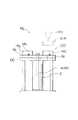
次に、第三実施例に係る成形機Mcについて、図9を参照して説明する。同図に示す成形機Mcは回転テーブル機構100を備える。この成形機Mcは、駆動装置2におけるシャフト4の先端(出力軸部4s)を、複数の成形用金型(固定型)14a,14bを支持する金型変更用回転テーブル6c(可動体6)に結合して構成した。
【0044】
これにより、回転テーブル6cを回転させる際は、最初に、駆動装置2の推力発生部5(図2)を制御することにより、シャフト4を前進(上昇)させ、基台102に載った回転テーブル6cを仮想線で示す位置まで若干持ち上げて基台102から離す。そして、この状態でロータリモータ部3(図2)を駆動制御して回転テーブル6cを、例えば、180゜回転させて成形用金型(固定型)14a,14bを切換える。この場合、成形用金型(固定型)14a,14bの停止位置は、前述したロータリエンコーダ47を利用してもよいし、別途配設した他の位置検出器(別途のロータリエンコーダ又はリミットスイッチ等)を利用してもよい。また、回転テーブル6cの回転が終了したなら、再び、シャフト4を後退(下降)させ、基台102に回転テーブル6cを載せる。なお、103は射出装置、104は可動型をそれぞれ示す。なお、図9は竪型の成形機を示したが横型の成形機に対しても同様に適用できることは勿論である。
【0045】
他方、図10〜図16には、駆動装置2の各種変更実施例を示す。図10及び図11は、図3における四極形ロータ部38の変更実施例を示す。図10のロータ部38aは、界磁巻線の発生する磁束の通過方向(回転軸方向)に沿って設けた各磁性体36a〜36dを複数の細分用非磁性体37x…によって回転方向へさらに細かく磁気的に分離した。なお、細分用非磁性体37x…による磁気的分離の程度は非磁性体37a〜37dよりも極めて小さい。具体的には、非磁性体37a〜37dの円周方向における厚さ(ギャップ)が3〜10mm程度とすれば、細分用非磁性体37x…の円周方向における厚さ(ギャップ)は0.3〜3mm程度に設定する。このようなロータ部38aを用いれば、電機子電流によって生ずる磁束の影響、即ち、電機子反作用を取り除くことができる。
【0046】
図11のロータ部38bは、界磁巻線の発生する磁束の通過方向(回転軸方向)に沿って設けた各磁性体36a〜36dを複数の細分用非磁性体37y…によって回転方向へさらに細かく磁気的に分離した点は図10と同じであるが、ロータ部38bでは細分用非磁性体37y…によって分離した磁性体36a〜36dの回転方向における厚さを、界磁コアから発生する磁束の正弦波状の分布密度に対応させた点がロータ部38aとは異なる。即ち、ロータ部38bの場合は、細分用非磁性体37y…によって分離された各磁性体36a〜36dの回転方向における厚さは正弦波状の磁束分布密度に対応して、各非磁性体37a〜37d間の中央付近では厚く、各非磁性体37a〜37d近傍では薄くなる。このようなロータ部38bを用いれば、界磁電流によって生じた正弦波状の磁束分布に対応した磁極(N極及びS極)をその外周面上に形成することができるため、回転特性を飛躍的に向上させることができる。
【0047】
図12は、図2における駆動装置2を軸方向Dsにシリーズ接続した変更実施例を示す。例示は二台の駆動装置2をシリーズ接続したが、三台以上であっても同様に接続することができる。なお、図12において、図2と同一部分には同一符号を付し、その構成を明確にした。このように複数台の駆動装置2をシリーズ接続すれば、接続台数に応じて制御可能な推力及び回転力を大きくすることができる。
【0048】
図13は、ロータ部38における各磁性体36a〜36dの外周面に、円筒帯状(円筒の一部を帯状に切り抜いたもの)の永久磁石110…をそれぞれ設けた変更実施例を示す。この場合、磁性体36a及び36cに設けた永久磁石110…は、ロータ部38に接する内周面側がN極になるとともに、電機子部33に対向する外周面側がS極になり、さらに、界磁部34及び35に対向する磁性体36a及び36cの端面がN極になる。同様に磁性体36b及び36dに設けた永久磁石110…は、ロータ部38に接する内周面側がS極になるとともに、電機子部33に対向する外周面側がN極になり、さらに、界磁部34及び35に対向する磁性体36b及び36dの端面がS極になる。
【0049】
また、この変更変更例の場合、界磁部34と35は位相角で90゜異なる界磁電流により励磁する。即ち、図13に示すようにロータ部38に対向する界磁部34がN極の場合は他方の界磁部35をS極に、ロータ部38に対向する界磁部34がS極の場合は他方の界磁部35をN極にそれぞれ励磁する。これにより、ロータ部38と界磁部35間には反発力が生じ、ロータ部38と界磁部34間には吸引力が発生する。このときにロータ部38が界磁部34又は35に対して接触又は近接した状態にあれば、励磁電流を流すことなしに永久磁石110による吸引力(推力)を維持できる。なお、シャフト4の軸方向Dsの位置制御や推力制御等は、前述した実施例と同様に界磁電流IfLとIfRを可変して行うことができる。また、図13の変更実施例であっても大きなトルクや推力を得ることを目的として、図12の変更実施例のように多段に組み合わせてもよい。
【0050】
よって、図13の変更変更例では、永久磁石110…を磁性体36a〜36dの外周に沿って設けたため、界磁巻線に界磁電流を流さなくてもロータ部38を回転させることができる。この場合、回転トルクは永久磁石110…の磁極の強さ及び電機子電流の大きさに依存するため、広範囲に渡って最適なトルク制御を行うことはできないが、界磁巻線に流れる電流の大きさを適宜制御すれば、永久磁石110…による磁束に、さらには界磁巻線から発生した磁束の大きさを適宜制御することにより、磁極の強さを制御できるハイブリッド形のロータ部38を構成でき、回転トルクを広範囲に制御可能になる。なお、図13において、図2と同一部分には同一符号を付し、その構成を明確にした。
【0051】
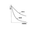
図14(図15)は、ロータ部38cの両端面をシャフト4に対して所定の角度で傾斜させた傾斜面(例えば、テーパ面等)111,112により形成するとともに、この傾斜面111,112に対向する界磁部34c,35cの幾何学的形状を当該傾斜面111,112に平行となるように構成した変更変更例を示す。これにより、ロータ部38cと界磁部34c及び35c間における磁気回路上のギャップ長d、さらにシャフト4の軸方向Dsにおける移動距離zの間には、移動距離zがギャップ長dよりも大きい関係、即ち、z>dの関係が成立する。したがって、短いギャップ長dにより、これよりも長い移動距離zを確保できるため、励磁電流の低減と推力の特性改善を共に行うことができる。図15には、図2の実施例で示したロータ部38の端面がシャフト4に対して垂直面となる場合と、図14の変更実施例で示したロータ部38cの端面を傾斜面111,112により構成した場合における移動距離zに対する推力Fzの関係を示す。図15から明らかなように、ロータ部38の端面がシャフト4に対して垂直面となる場合には、移動距離zが大きくなるに従って推力Fzは激減する。これに対して傾斜面111,112により構成した場合には、移動距離zが大きくなった場合でも垂直面の場合に比べて推力Fzの減少は少なく、推力Fzは移動距離に対して緩やかに減少する。これは前述のように、ギャップ長dが同じ場合に、垂直構造のものに比べて傾斜構造の方が移動距離zが大きいためである。
【0052】
この変更変更例では、ロータ部38cと界磁部34c及び35c間に働く力、即ち、吸引力Fは、ロータ部38cの端面、即ち、傾斜面111,112の表面に垂直な方向に発生する。この吸引力Fは軸方向の力Fz(推力)と径方向の力Fxに分力される。径方向の力Fzは互いに打ち消し合うが、軸方向の力Fz(推力)は一方向にまとまり、その大きさはロータ部38cの端面がシャフト4に垂直な構造の場合とほとんど変わらない。したがって、界磁部34c及び35cによって生成される磁束Φ1及びΦ2の大きさを制御することにより、軸方向及び径方向双方に機能する磁気軸受けとして利用できる。なお、図14では、ロータ部38cの両端面を傾斜面111,112としたが、このような傾斜面はいずれか一方の端面のみに適用してもよい。
【0053】
図16は、図2のロータ部38の磁性体36a〜36dとシャフト4間に介在させた非磁性体37a〜37dの代わりに、磁性体36a及び36cに対してS極が対向し、かつ磁性体36b及び36dに対してN極が対向する永久磁石113a〜113dを介在させたものであり、ロータ部38の変更変更例を示す。
【0054】
以上、実施例について詳細に説明したが、本発明はこのような実施例に限定されるものではなく、細部の構成,形状,手法,数量等において、本発明の要旨を逸脱しない範囲で任意に変更,追加,削除することができる。
【0055】
例えば、成形機の種類や内容は例示に限定されることなく任意の成形機に適用できる。一方、図2及び図14の実施例では、界磁部をロータ部の両側に設けたが、いずれか一方に設けてもよいし、図12のように多段接続した場合もいずれか一方だけに界磁部を設けてもよい。界磁部を一方に設けた場合、他方向にはスプリング等の弾性手段により復帰させればよい。また、図2又は図14のシャフトを一方の軸受のみで支持してもよい。特に、図14の場合には径方向に吸引力が作用しているので、軸受として有効である。さらに、四極二十四スロット又は二極十二スロットの同期電動機を例示したが、極数とスロット数の関係はこれに限定されるものではなく、任意の組み合わせを採用できるとともに、他の原理に基づく電動機の使用を排除するものではない。また、図4では界磁巻線を単層重巻を例に説明したが、これに限らず二層重巻にしてもよい。さらに、ロータ部を電機子部の内側に存在するタイプを例示したが、ロータ部が電機子部の外側に存在する、いわゆるアウタロータの場合にも同様に適用できる。
【0056】
【発明の効果】
このように、本発明に係る成形機は、ロータリモータ部のシャフトを軸方向へ変位自在に設けるとともに、シャフトを軸方向へ移動させる推力発生部を設け、シャフトを可動体に接続することにより、当該可動体を、ロータリモータ部により回転駆動し、かつこのロータリモータ部のケーシング内部に設けた推力発生部により進退駆動する駆動装置を備えるため、部品点数の削減による全体構造の簡略化及び小型化、さらには信頼性向上及び大幅なコストダウンを図ることができるという顕著な効果を期待でき、特に、プリプラ式射出成形機,インラインスクリュ式射出成形機及び付属する回転テーブル機構等に適用して最適となる。
【図面の簡単な説明】
【図1】本発明の第一実施例に係る成形機(インラインスクリュ式射出成形機)を示す模式的構成図、
【図2】同成形機に備える駆動装置の断面側面図、
【図3】図2中A−A線断面図、
【図4】図2中B−B線から見た界磁部の原理構成図、
【図5】同駆動装置における界磁部を構成する界磁コアのC−C線断面図及びD−D線断面図、
【図6】同駆動装置における電機子巻線と界磁巻線の結線図、
【図7】同駆動装置をACサーボモータシステムとして構成したブロック回路図、
【図8】本発明の第二実施例に係る成形機(プリプラ式射出成形機)を示す一部断面構成図、
【図9】本発明の第三実施例に係る成形機(回転テーブル機構)を示す構成図、
【図10】図2に示す四極形ロータ部の変更実施例を示す断面正面図、
【図11】図2に示す四極形ロータ部の他の変更実施例を示す断面正面図、
【図12】図2に示す駆動装置の変更実施例を示す断面側面図、
【図13】同駆動装置の他の変更実施例を示す断面側面図、
【図14】同駆動装置の他の変更実施例を示す断面側面図、
【図15】図2と図14に示す駆動装置の軸方向におけるロータ部の移動距離と推力の関係を示す特性図、
【図16】図2に示す四極形ロータ部の他の変更実施例を示す断面正面図、
【符号の説明】
Ma 成形機(インラインスクリュ式射出成形機)
Mb 成形機(プリプラ式射出成形機)
Mc 成形機(回転テーブル機構)
2 駆動装置
3 ロータリモータ部
4 シャフト
5 推力発生部
6 可動体
6a スクリュ
6b スクリュ
6c 金型変更用回転テーブル
7 ケーシング
10 可塑化装置
11 加熱シリンダ
12 樹脂通路
13 弁部
14a 成形用金型
14b 成形用金型
Ds 軸方向
Fxd 位置検出機能部
Fvd 速度検出機能部
Fpd 圧力検出機能部
Sxd 位置検出値
Svd 速度検出値
Spd 圧力検出値
Fxs 位置制御機能部
Fvs 速度制御機能部
Fps 圧力制御機能部
Sxs 位置設定値
Svs 速度設定値
Sps 圧力設定値[0001]
TECHNICAL FIELD OF THE INVENTION
The present invention relates to a molding machine provided with a driving device that rotationally drives and moves a movable body such as a screw.
[0002]
[Prior art and problems]
2. Description of the Related Art Conventionally, an in-line screw type injection molding machine equipped with an electric driving device for rotationally driving and moving a screw forward and backward is known from Japanese Patent Application Laid-Open No. 9-11290.
[0003]
This type of injection molding machine includes a metering-side drive unit using a first servomotor that rotationally drives a screw and an injection-side drive unit that uses a second servomotor that drives the screw forward and backward. In the injection process, the molding resin is plasticized and measured by rotating the screw with the drive unit on the metering side, and in the injection process, the metered resin is injected and filled into the mold by advancing the screw with the drive unit on the injection side. . As described above, in the field of molding machines, there are many cases where a driving device that drives a movable body such as a screw by two kinds of different movements is used.
[0004]
However, since such a conventional driving device uses one servo motor for each different driving unit, the number of servo motors according to the number of driving units is required, and the movable body is moved in the reciprocating direction. In the drive unit, a motion conversion mechanism such as a ball screw mechanism for converting the rotary motion of the servo motor into a linear motion is required in addition to the servo motor. However, there is a problem that the reliability is reduced and the overall cost is significantly increased.
[0005]
The present invention has solved the above-mentioned problems in the prior art, and is a molding machine capable of simplifying and miniaturizing the entire structure by reducing the number of parts, and further improving reliability and significantly reducing cost. The purpose is to provide.
[0006]
Means and Embodiments for Solving the Problems
The molding machines Ma, Mb, Mc according to the present invention provide the
[0007]
In this case, according to the preferred embodiment, the
[0008]
As a result, the structure, size, and the like of the
[0009]
【Example】
Next, preferred embodiments according to the present invention will be described in detail with reference to the drawings.
[0010]
First, an inline screw injection molding machine Ma, which is a molding machine according to a first embodiment, will be described with reference to FIGS.
[0011]
The in-line screw type injection molding machine Ma shown in FIG. 1 includes a mold clamping device Mc to which a mold is attached and an injection device Mi. The injection device Mi is provided with a
[0012]
The
[0013]
The
[0014]
Each of the
[0015]
Similarly to the
[0016]
In this case, the
[0017]
On the other hand, the
[0018]
The operation of the
[0019]
The magnetic flux distribution of the magnetic field at the magnetic poles (N-pole and S-pole) generated by the
[0020]
That is, the
[0021]
More specifically, the magnetic flux Φ1 generated from the two north poles of the
[0022]
As described above, in the
[0023]
On the other hand, if the
[0024]
By the way, when the magnitude of the magnetic flux Φ1 generated by the
[0025]
The magnitude of the thrust is determined according to the difference between the field current IfL supplied to the
[0026]
Next, a control system for the
[0027]
The
[0028]
If such a
[0029]
FIG. 6 shows a method of connecting the
[0030]
FIG. 7 shows a specific configuration of the
[0031]
First, a detection signal S2 indicating the rotation speed (rotation position) of the
[0032]
On the other hand, the control system of the field current is a form in which the
[0033]
By configuring the AC servo motor system shown in FIG. 7, the
[0034]
Therefore, the operation of the in-line screw injection molding machine Ma equipped with such a
[0035]
Next, a pre-plastic injection molding machine Mb according to a second embodiment will be described with reference to FIG.
[0036]
The plastic injection molding machine Mb includes a
[0037]
The
[0038]
On the other hand, a
[0039]
On the other hand, the
[0040]
The
[0041]
The operation of such a pre-plastic injection molding machine Mb is as follows. First, at the start of weighing, the thrust generating unit 5 (FIG. 2) of the
[0042]
Then, since the
[0043]
Next, a molding machine Mc according to a third embodiment will be described with reference to FIG. The molding machine Mc shown in FIG. In this molding machine Mc, the tip of the shaft 4 (the
[0044]
Thus, when rotating the rotary table 6 c, first, the
[0045]
10 to 16 show various modified embodiments of the
[0046]
In the
[0047]
FIG. 12 shows a modified embodiment in which the
[0048]
FIG. 13 shows a modified embodiment in which a cylindrical belt-shaped (a part of a cylinder is cut into a band shape)
[0049]
In the case of this modification, the
[0050]
Therefore, in the modification shown in FIG. 13, since the
[0051]
FIG. 14 (FIG. 15) shows that both end surfaces of the
[0052]
In this modified example, the force acting between the
[0053]
FIG. 16 shows an arrangement in which the S pole faces the
[0054]
Although the embodiment has been described in detail above, the present invention is not limited to such an embodiment, and the configuration, shape, method, quantity, and the like of the details can be arbitrarily set without departing from the gist of the present invention. Can be changed, added, or deleted.
[0055]
For example, the type and content of the molding machine are not limited to the examples and can be applied to any molding machine. On the other hand, in the embodiments shown in FIGS. 2 and 14, the field portions are provided on both sides of the rotor portion, but they may be provided on any one of them, or in the case of multi-stage connection as shown in FIG. A field portion may be provided. When the field portion is provided on one side, it may be returned in the other direction by an elastic means such as a spring. Further, the shaft of FIG. 2 or FIG. 14 may be supported by only one bearing. In particular, in the case of FIG. 14, since the suction force acts in the radial direction, it is effective as a bearing. Furthermore, although a synchronous motor having 24 poles and 24 slots or a 2-pole and 12 slots has been exemplified, the relationship between the number of poles and the number of slots is not limited to this, and any combination can be adopted and other principles can be adopted. It does not preclude the use of electric motors based on them. Further, in FIG. 4, the field winding is described as an example of a single-layer double winding, but is not limited thereto, and may be a double-layer double winding. Further, the type in which the rotor portion is present inside the armature portion has been illustrated, but the present invention can be similarly applied to a so-called outer rotor in which the rotor portion exists outside the armature portion.
[0056]
【The invention's effect】
As described above, the molding machine according to the present invention provides the shaft of the rotary motor unit so as to be displaceable in the axial direction, and the thrust generating unit that moves the shaft in the axial direction, and connects the shaft to the movable body. Since the movable body is provided with a driving device that is driven to rotate by a rotary motor unit and is driven forward and backward by a thrust generating unit provided inside the casing of the rotary motor unit, the overall structure is simplified and downsized by reducing the number of parts. In addition, it can be expected to have a remarkable effect that reliability can be improved and significant cost reduction can be achieved. Especially, it is optimally applied to pre-plastic injection molding machine, in-line screw injection molding machine and attached rotary table mechanism, etc. It becomes.
[Brief description of the drawings]
FIG. 1 is a schematic configuration diagram showing a molding machine (in-line screw type injection molding machine) according to a first embodiment of the present invention;
FIG. 2 is a sectional side view of a driving device provided in the molding machine;
FIG. 3 is a sectional view taken along line AA in FIG. 2;
FIG. 4 is a principle configuration diagram of a field portion viewed from line BB in FIG. 2;
FIG. 5 is a cross-sectional view taken along a line CC and a line DD of a field core constituting a field portion in the driving device.
FIG. 6 is a connection diagram of an armature winding and a field winding in the driving device,
FIG. 7 is a block circuit diagram in which the driving device is configured as an AC servomotor system;
FIG. 8 is a partial cross-sectional configuration diagram showing a molding machine (prepra-type injection molding machine) according to a second embodiment of the present invention;
FIG. 9 is a configuration diagram showing a molding machine (rotary table mechanism) according to a third embodiment of the present invention;
FIG. 10 is a sectional front view showing a modified example of the quadrupole rotor shown in FIG. 2;
11 is a sectional front view showing another modified example of the quadrupole rotor portion shown in FIG. 2;
FIG. 12 is a sectional side view showing a modified embodiment of the drive device shown in FIG. 2;
FIG. 13 is a cross-sectional side view showing another modified embodiment of the drive device.
FIG. 14 is a cross-sectional side view showing another modified embodiment of the driving device.
15 is a characteristic diagram showing a relationship between a moving distance of a rotor unit and a thrust in an axial direction of the driving device shown in FIGS. 2 and 14;
FIG. 16 is a sectional front view showing another modified embodiment of the quadrupole rotor shown in FIG. 2;
[Explanation of symbols]
Ma molding machine (in-line screw injection molding machine)
Mb molding machine (Pre-plastic injection molding machine)
Mc molding machine (rotary table mechanism)
2 Drive
3 Rotary motor section
4 shaft
5 Thrust generator
6 movable body
6a screw
6b screw
6c Rotary table for mold change
7 Casing
10 Plasticizer
11 heating cylinder
12 Resin passage
13 Valve
14a Mold for molding
14b Mold for molding
Ds axial direction
Fxd position detection function
Fvd speed detection function
Fpd pressure detection function
Sxd position detection value
Svd speed detection value
Spd pressure detection value
Fxs position control function unit
Fvs speed control function
Fps pressure control function
Sxs position setting value
Svs speed setting value
Sps pressure set value
Claims (7)
Translated fromJapanesePriority Applications (3)
| Application Number | Priority Date | Filing Date | Title |
|---|---|---|---|
| JP12222898AJP3593671B2 (en) | 1998-05-01 | 1998-05-01 | Molding machine |
| US09/301,761US6247913B1 (en) | 1998-05-01 | 1999-04-29 | Molding machine |
| US09/362,467US6426577B1 (en) | 1998-05-01 | 1999-07-28 | Thrust-controllable rotary synchronous machine |
Applications Claiming Priority (1)
| Application Number | Priority Date | Filing Date | Title |
|---|---|---|---|
| JP12222898AJP3593671B2 (en) | 1998-05-01 | 1998-05-01 | Molding machine |
Publications (2)
| Publication Number | Publication Date |
|---|---|
| JPH11309763A JPH11309763A (en) | 1999-11-09 |
| JP3593671B2true JP3593671B2 (en) | 2004-11-24 |
Family
ID=14830749
Family Applications (1)
| Application Number | Title | Priority Date | Filing Date |
|---|---|---|---|
| JP12222898AExpired - Fee RelatedJP3593671B2 (en) | 1998-05-01 | 1998-05-01 | Molding machine |
Country Status (2)
| Country | Link |
|---|---|
| US (1) | US6247913B1 (en) |
| JP (1) | JP3593671B2 (en) |
Families Citing this family (25)
| Publication number | Priority date | Publication date | Assignee | Title |
|---|---|---|---|---|
| JP3725323B2 (en)* | 1998-02-23 | 2005-12-07 | 日創電機株式会社 | Drive motor and drive device for molding machine |
| JP4110365B2 (en)* | 2000-02-07 | 2008-07-02 | 株式会社名機製作所 | Injection molding machine |
| WO2003026878A1 (en)* | 2001-09-26 | 2003-04-03 | Hunstman International Llc | Molding system with self-releasing moveable member |
| JP2003170471A (en)* | 2001-12-10 | 2003-06-17 | Toshiba Mach Co Ltd | Injecting unit for injection molding machine or the like |
| TW200405646A (en)* | 2002-05-24 | 2004-04-01 | Virginia Tech Intell Prop | Method, apparatus, and system for drive control, power conversion, and start-up control in an SRM or PMBDCM drive system |
| US20050156352A1 (en)* | 2002-06-21 | 2005-07-21 | Krauss-Maffei Kunststofftechnik Gmbh | Method of and apparatus for injection molding multicomponent fiber-reinforced molded parts |
| JP2004209783A (en)* | 2002-12-27 | 2004-07-29 | Aoki Technical Laboratory Inc | Electromotive injection unit |
| JP4417653B2 (en)* | 2003-06-10 | 2010-02-17 | ライフェンホイザー・ゲゼルシャフト・ミト・ベシュレンクテル・ハフツング・ウント・コンパニー・コマンデイトゲゼルシャフト・マシイネンファブリーク | Smoothing device |
| DE10337551B4 (en)* | 2003-08-14 | 2005-07-07 | Demag Ergotech Gmbh | Pressure measuring device for an injection molding machine |
| DE102004028355B4 (en)* | 2004-06-11 | 2011-12-29 | Siemens Ag | driving means |
| DE102005055491B4 (en)* | 2005-11-18 | 2009-09-10 | Siemens Ag | Drive for a plastic injection molding machine |
| TW200722268A (en)* | 2005-12-05 | 2007-06-16 | Ind Tech Res Inst | Injection unit of two-step injection molding machine |
| US20070296121A1 (en)* | 2006-06-07 | 2007-12-27 | Husky Injection Molding Systems Ltd. | Molding-system drive |
| US20080042322A1 (en)* | 2006-08-15 | 2008-02-21 | Husky Injection Molding Systems Ltd. | Platen-stroke actuator of molding system, amongst other things |
| JP4658887B2 (en)* | 2006-09-25 | 2011-03-23 | 日精樹脂工業株式会社 | Data processing method for injection molding machine |
| JP5052253B2 (en)* | 2007-08-07 | 2012-10-17 | 東洋機械金属株式会社 | Molding machine |
| US8393884B2 (en)* | 2010-06-22 | 2013-03-12 | Pascal Engineering Corporation | Ejector device of injection molding machine |
| JP2014165927A (en)* | 2013-02-21 | 2014-09-08 | Kenji Narita | Permanent magnet type synchronous motor |
| JP5647307B1 (en)* | 2013-06-04 | 2014-12-24 | 成田 憲治 | DC excitation field synchronous motor |
| CN104716766A (en)* | 2013-12-13 | 2015-06-17 | 博立码杰通讯(深圳)有限公司 | Electromagnetic motor |
| FR3022707B1 (en) | 2014-06-20 | 2017-11-17 | Whylot | ELECTROMAGNETIC SYNCHRONOUS MOTOR WITH MAGNETIC FLOWS COMBINED AXIAL AND RADIAL WITH DOUBLE EXCITATION. |
| WO2016084204A1 (en)* | 2014-11-27 | 2016-06-02 | 成田 憲治 | Synchronous motor |
| KR20180079338A (en)* | 2015-11-02 | 2018-07-10 | 테트라 라발 홀딩스 앤드 피낭스 소시에떼아노님 | Molding assembly |
| JP6193456B1 (en)* | 2016-08-25 | 2017-09-06 | 株式会社ソシオリカ | Synchronous motor |
| JP6762829B2 (en)* | 2016-09-30 | 2020-09-30 | 住友重機械工業株式会社 | Injection molding machine |
Family Cites Families (4)
| Publication number | Priority date | Publication date | Assignee | Title |
|---|---|---|---|---|
| JP2571523B2 (en)* | 1993-09-28 | 1997-01-16 | 日精樹脂工業株式会社 | Injection screw |
| JP2881291B2 (en) | 1995-06-30 | 1999-04-12 | 日精樹脂工業株式会社 | Control method and device for injection molding machine |
| US5891485A (en)* | 1997-05-30 | 1999-04-06 | Sumitomo Heavy Industries, Ltd. | Built-in motor type electric injection molding apparatus |
| US6024558A (en)* | 1998-05-04 | 2000-02-15 | Husky Injection Molding Systems Ltd. | Frameless electric drive for turret machine |
- 1998
- 1998-05-01JPJP12222898Apatent/JP3593671B2/ennot_activeExpired - Fee Related
- 1999
- 1999-04-29USUS09/301,761patent/US6247913B1/ennot_activeExpired - Fee Related
Also Published As
| Publication number | Publication date |
|---|---|
| JPH11309763A (en) | 1999-11-09 |
| US6247913B1 (en) | 2001-06-19 |
Similar Documents
| Publication | Publication Date | Title |
|---|---|---|
| JP3593671B2 (en) | Molding machine | |
| US6051896A (en) | Molding machine | |
| US20090017151A1 (en) | Drive apparatus for injection molding machine, injection apparatus, and mold clamping apparatus | |
| US6124648A (en) | Molding machine | |
| JP6385854B2 (en) | Brushless motor | |
| JPS6342826A (en) | Mold clamping device in injection molder | |
| JP5680513B2 (en) | Strain sensor mounting structure and strain measuring device | |
| JP2001088180A (en) | Injection molding machine | |
| JPH11243675A (en) | Drive motor and drive for molding machine | |
| JP2009248476A (en) | Mold clamping device | |
| JP5063225B2 (en) | Molding machine | |
| JPS61154823A (en) | Method of controlling clamping force of injection molding machine | |
| JP5792278B2 (en) | Molding machine | |
| KR102689296B1 (en) | electric injection molding machine | |
| JP2007312575A (en) | Linear drive | |
| KR101417594B1 (en) | Injection molding machine | |
| JPH0382350A (en) | Electric motor field rotor and its manufacturing method | |
| JP2002125355A (en) | Motor-driven injection molder and brushless three-phase dc motor | |
| JP2003320565A (en) | Injection equipment for injection molding machine and controlling method therefor | |
| US20250044381A1 (en) | Method of magnetic orientation determination of injection molded permanent magnets | |
| JP2006197722A (en) | Linear drive | |
| JP2002096365A (en) | Pressure controlling device for injection molding machine and method for controlling pressure | |
| JP2010064349A (en) | Molding machine | |
| JP2004343843A (en) | Dc linear motor and electric injection molding machine using the same | |
| JP2003145580A (en) | Injection molding machine |
Legal Events
| Date | Code | Title | Description |
|---|---|---|---|
| A977 | Report on retrieval | Free format text:JAPANESE INTERMEDIATE CODE: A971007 Effective date:20040408 | |
| A131 | Notification of reasons for refusal | Free format text:JAPANESE INTERMEDIATE CODE: A131 Effective date:20040512 | |
| A521 | Request for written amendment filed | Free format text:JAPANESE INTERMEDIATE CODE: A523 Effective date:20040708 | |
| TRDD | Decision of grant or rejection written | ||
| A01 | Written decision to grant a patent or to grant a registration (utility model) | Free format text:JAPANESE INTERMEDIATE CODE: A01 Effective date:20040804 | |
| A61 | First payment of annual fees (during grant procedure) | Free format text:JAPANESE INTERMEDIATE CODE: A61 Effective date:20040820 | |
| R150 | Certificate of patent or registration of utility model | Free format text:JAPANESE INTERMEDIATE CODE: R150 | |
| FPAY | Renewal fee payment (event date is renewal date of database) | Free format text:PAYMENT UNTIL: 20100910 Year of fee payment:6 | |
| FPAY | Renewal fee payment (event date is renewal date of database) | Free format text:PAYMENT UNTIL: 20100910 Year of fee payment:6 | |
| FPAY | Renewal fee payment (event date is renewal date of database) | Free format text:PAYMENT UNTIL: 20110910 Year of fee payment:7 | |
| FPAY | Renewal fee payment (event date is renewal date of database) | Free format text:PAYMENT UNTIL: 20110910 Year of fee payment:7 | |
| FPAY | Renewal fee payment (event date is renewal date of database) | Free format text:PAYMENT UNTIL: 20120910 Year of fee payment:8 | |
| FPAY | Renewal fee payment (event date is renewal date of database) | Free format text:PAYMENT UNTIL: 20120910 Year of fee payment:8 | |
| FPAY | Renewal fee payment (event date is renewal date of database) | Free format text:PAYMENT UNTIL: 20130910 Year of fee payment:9 | |
| R250 | Receipt of annual fees | Free format text:JAPANESE INTERMEDIATE CODE: R250 | |
| R250 | Receipt of annual fees | Free format text:JAPANESE INTERMEDIATE CODE: R250 | |
| R250 | Receipt of annual fees | Free format text:JAPANESE INTERMEDIATE CODE: R250 | |
| LAPS | Cancellation because of no payment of annual fees |