JP3593433B2 - Liquid crystal display device and repair method thereof - Google Patents
Liquid crystal display device and repair method thereofDownload PDFInfo
- Publication number
- JP3593433B2 JP3593433B2JP2317397AJP2317397AJP3593433B2JP 3593433 B2JP3593433 B2JP 3593433B2JP 2317397 AJP2317397 AJP 2317397AJP 2317397 AJP2317397 AJP 2317397AJP 3593433 B2JP3593433 B2JP 3593433B2
- Authority
- JP
- Japan
- Prior art keywords
- liquid crystal
- crystal display
- front frame
- mounting arm
- display device
- Prior art date
- Legal status (The legal status is an assumption and is not a legal conclusion. Google has not performed a legal analysis and makes no representation as to the accuracy of the status listed.)
- Expired - Fee Related
Links
- 239000004973liquid crystal related substanceSubstances0.000titleclaimsdescription50
- 238000000034methodMethods0.000titleclaimsdescription12
- 230000008439repair processEffects0.000titledescription3
- 229920003002synthetic resinPolymers0.000claimsdescription4
- 239000000057synthetic resinSubstances0.000claimsdescription4
- 238000009792diffusion processMethods0.000description2
- 238000007689inspectionMethods0.000description2
- 239000002184metalSubstances0.000description2
- 238000005452bendingMethods0.000description1
- 238000010030laminatingMethods0.000description1
Images


Landscapes
- Liquid Crystal (AREA)
- Devices For Indicating Variable Information By Combining Individual Elements (AREA)
Description
Translated fromJapanese【0001】
【発明の属する技術分野】
本発明は、枠体の分解を簡単にして、液晶表示体の修理、交換が容易な液晶表示装置及びこの修理方法に関する。
【0002】
【従来の技術】
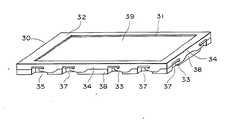
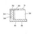
従来における液晶表示装置は、図6、図7に示すように、金属板から成る前面枠体30は、開口31を有する前面板32と、複数の取付脚33を有する側板34とで構成され、また、合成樹脂から成る箱形の背面枠体35は、背面板36と、複数の凹部37を有する側板38とで構成されている。
また、ここでは図示しないが、液晶表示素子、駆動用プリント基板、導光体、反射板、拡散板等が積層されて構成されて成る液晶表示体39が、前記背面枠体35に収納され、前記取付脚33を前記凹部37に折り曲げ係止して、背面枠体35の背面板36と前面枠体30の前面板32とで液晶表示体39が挟持されて取り付けられている。
【0003】
このような液晶表示装置は、高価なため、液晶表示体39を構成する部品が故障、或いは破損等を生じた時、部品の修理、又は交換が行なわれる。
そして、従来においては、液晶表示装置の検査工程で液晶表示体39に問題が発見されたり、或いは使用途上において故障、破損が生じた時、先ず、折り曲げられた取付脚33を、元の状態に折り曲げて戻し、前面枠体30と背面枠体35とを分解する。
しかる後、液晶表示体39を取り出し、液晶表示体39の部品の修理、交換を行った後、再度、液晶表示体39を背面枠体35に収納し、そして、前面枠体30を被せ、取付脚33を凹部37に折り曲げ係止するものである。
【0004】
【発明が解決しようとする課題】
従来の液晶表示装置においては、前面枠体30の側板34に設けた取付脚33を、背面枠体35の凹部37に折り曲げ係止するものであるため、組立作業性が悪く、コスト高になるばかりか、液晶表示体39の部品の修理、交換においても、枠体の分解のために、取付脚33を元の状態に折り曲げて戻さねばならず、その分解作業が面倒で、手間が掛かると言う問題がある。
また、取付脚33は、組立、分解、更に組立と、そのたび毎に折り曲げを繰り返すため、取付脚33に疲労が生じて折れを起こして破損するという問題がある。
【0005】
【課題を解決するための手段】
前記課題を解決するための第1の解決手段として、前面枠体と、背面枠体と、前記前面枠体と前記背面枠体とで挟持されて取り付けられる液晶表示体とを備え、前記前面枠体の側板には凹部を形成し、また、前記背面枠体の側板には前記凹部に嵌入する凸部を備えたバネ性を有する取付腕部を設けると共に、該取付腕部の端面に対向する前記前面枠体の前面板に、前記端面に対向して孔を設けた構成とした。
また、第2の解決手段として、前記取付腕部は、二つの前記凸部間に、前記孔に対向する溝部を備えた構成とした。
また、第3の解決手段として、前記背面枠体を合成樹脂で形成し、前記取付腕部を複数設け、該複数の取付腕部と対向する前記前面枠体に、複数の前記孔をそれぞれ形成した構成とした。
また、第4の解決手段として、前面枠体と背面枠体とで液晶表示体を挟持し、前記前面枠体の側板には、凹部を形成し、前記背面枠体の側板には、前記凹部に嵌入する凸部を形成したバネ性を有する取付腕部を設け、該取付腕部の端面と対向する前記前面枠体の前面板に、前記端面に対向して孔を形成し、該孔から治具を差し込むと、前記取付腕部が撓み前記凹部と前記凸部との係合がはずれるようにした液晶表示装置の修理方法。
また、第5の解決手段として、前記取付腕部を複数形成し、該複数の取付腕部と対向して複数の前記孔をそれぞれ形成し、前記複数の孔に対応する数の複数の前記治具を一個の保治具に取り付けて、前記複数の治具を同時に前記孔に差し込むようにした液晶表示装置の修理方法。
【0006】
【発明の実施の形態】
本発明における液晶表示装置を、図1ー図5に示した実施例に基づきを説明する。
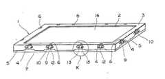
金属板から成る前面枠体1は、開口2を有する矩形の前面板3と、該前面板3の周囲から下方に折り曲げられ、孔から成る複数個の凹部4を有する側板5と、前記各凹部4の近傍の前面板3に設けられた複数個の孔6とを備えている。
また、合成樹脂から成る箱状の背面枠体7は、背面板8と、該背面板8の周囲から上方に延びる側板9と、該側板9に形成されたバネ性のある複数個の取付腕部10と、側板9の取付腕部10の両側に設けられた切り込み部11とを備えている。
【0007】
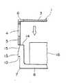
そして、前記取付腕部10は、外側部に、上下方向に形成された溝部12を挟んでその両側に設けられた二つの凸部13と、下方から端面14側に傾斜して、前記凸部13の上面に設けられた傾斜部15とを有している。
また、これらの取付腕部10は、前記凹部4に対応して形成されており、凸部13は凹部4に嵌入可能で、また、端面14は、前面枠体1の前面板3に設けられた孔6に対向するように成っている。
【0008】
また、液晶表示体16は、ここでは図示しないが、液晶表示素子、駆動用プリント基板、導光体、反射板、拡散板等が順次積層されて構成されており、この液晶表示体16は、背面枠体7の空洞部に収納され、取付腕部10の凸部13を前面枠体1の凹部4に嵌入して、前面枠体1と背面枠体7とが組み合わされると共に、液晶表示体16が両枠体1と7とで挟持されて取り付けられる。
この時、取付腕部10の端面14、及び溝部12は前面板3に設けられた孔6と対向状態にあると共に、傾斜部15の上部は凹部4から若干抜け出た状態となっている。
【0009】
次に、液晶表示装置の組立について説明すると、先ず、図3に示すように、液晶表示体16を背面枠体7に収納し、次に、この上方から前面枠体1を被せ、矢印方向に前面枠体1を押し込む。
すると、前面枠体1の側板5の下端部が取付腕部10の傾斜部15に当接して、取付腕部10を内方に撓ませながら下方に押し込まれ、取付腕部10は図4の実線で示すように、凸部13の下端が凹部4に一致した状態になると、凸部13は取付腕部10のバネ性によって、点線で示すように凹部4に嵌入して係止する。
この時、取付腕部10の端面14、及び溝部12は孔6に対向すると共に、傾斜部15の上部は、凹部4から抜け出た状態となり、且つ、液晶表示体16は、前面板3と背面板8とで挟持されて取り付けられる。
このようにして、液晶表示装置の組立が完了する。
【0010】
また、このようにして組み立てられた液晶表示装置において、検査工程で液晶表示体16に問題が発見されたり、或いは使用途上において故障、破損が生じた時の修理方法として、図5に示すように、先ず、先端がくさび形状の複数個の治具17を、一個の保持具(図示せず)に取り付けたものを用意しておく。
そして、複数個の治具17を、前面枠体1の角穴6に対向させて配置した後、各治具17を同時に孔6に差し込むと、治具17は溝部12をガイドにして取付腕部10を内方、即ち、凸部13が凹部4との係合が外れる方向に取付腕部10が撓み、係合が外れた状態において、背面枠体7を前面枠体1から抜き出す。
しかる後、背面枠体7から液晶表示体16を取り出し、液晶表示体16の部品の修理、交換を行った後、再度、液晶表示体16を背面枠体7に収納し、そして、前述したように、前面枠体1を背面枠体7に被せて、押し込むと、取付腕部10の凸部13が凹部4に係止して、両枠体1、7が組み合わせるようになる。
【0011】
前記実施例において、前面枠体1を背面枠体に、また、背面枠体7を前面枠体に使用しても良く、この場合、枠体を分解するときは、治具17を下方に位置した状態で、孔6に治具17を差し込むようになる。
【0012】
【発明の効果】
本発明によれば、バネ性を有する取付腕部の凸部を凹部に嵌合して取り付けると共に、取付腕部の端部に対向して、前面板、又は背面板に孔を設けたものであるため、前面枠体と背面枠体との取付は、両者をはめ合わせるだけで組立が出来、その組立が簡単で生産性が良好で、また、孔に治具を差し込むだけで、両枠体の分解が可能となって、液晶表示体の部品の修理、交換が容易となる。
また、二つの凸部間に溝部を設けることによって、この溝部が治具の挿入時のガイドの役目をなし、枠体の分解が容易になる。
更に、背面枠体に複数個の取付腕部を設けることによって、液晶表示体の上面を上にして、正常な状態での組立、枠体の分解が出来、その作業を容易にすることができる。
【図面の簡単な説明】
【図1】本発明の液晶表示装置の斜視図。
【図2】本発明の液晶表示装置に係り、図1のK部の拡大斜視図。
【図3】本発明の液晶表示装置に係り、その組立方法を示す説明図。
【図4】本発明の液晶表示装置に係り、その組立方法を示す説明図。
【図5】本発明の液晶表示装置に係り、その分解方法を示す説明図。
【図6】従来の液晶表示装置の斜視図。
【図7】従来の液晶表示装置の要部断面図。
【符号の説明】
1 前面枠体
2 開口
3 前面板
4 凹部
5 側板
6 孔
7 背面枠体
8 背面板
9 側板
10 取付腕部
11 切り込み部
12 溝部
13 凸部
14 端面
15 傾斜部
16 液晶表示体
17 治具[0001]
TECHNICAL FIELD OF THE INVENTION
The present invention relates to a liquid crystal display device in which a frame is easily disassembled and a liquid crystal display is easily repaired and replaced,and a method forrepairing the liquid crystal display.
[0002]
[Prior art]
In a conventional liquid crystal display device, as shown in FIGS. 6 and 7, a
Although not shown here, a
[0003]
Since such a liquid crystal display device is expensive, when a component constituting the
Conventionally, when a problem is found in the liquid
Thereafter, the
[0004]
[Problems to be solved by the invention]
In the conventional liquid crystal display device, since the
Further, since the
[0005]
[Means for Solving the Problems]
As a first solution for solving the above-mentioned problem, the front frame includes a front frame, a rear frame, and a liquid crystal display body which is attached by being sandwiched between the front frame and the rear frame. bodyto form a recesson the sideplate of, also facing with theside plate of the rear frame body provided with attachment arms having a spring property provided with a convex portion that fits into the recess, the end face of the mounting arms A hole is provided in the frontplate of the front frame to face the end face.
Further, as a second solving means, the mounting arm portion is provided with a groove portion facing the hole between the two convex portions.
Further, a third aspect of the present invention, the rear frame body formed of a syntheticresin, aplurality ofpre-Symbol mounting armportion, said front frame member facing the mounting arm portion of the plurality of the plurality of the holes, respectively The configuration wasformed .
Further, as a fourth solution, a liquid crystal display is sandwiched between a front frame and a rear frame, a recess is formed in a side plate of the front frame, and the recess is formed in a side plate of the rear frame. A mounting arm portion having a spring property formed with a convex portion that fits into the mounting arm portion is provided, and a hole is formed on the front plate of the front frame body facing the end surface of the mounting arm portion so as to face the end surface. A method for repairing a liquid crystal display device, wherein when a jig is inserted, the mounting arm portion is bent to disengage the concave portion and the convex portion.
Further, as a fifth solution, a plurality of the mounting arms are formed, a plurality of the holes are respectively formed to face the plurality of the mounting arms, and a plurality of the repairs corresponding in number to the plurality of the holes are formed. A method of repairing a liquid crystal display device, wherein the jigs are attached to one jig, and the plurality of jigs are simultaneously inserted into the holes.
[0006]
BEST MODE FOR CARRYING OUT THE INVENTION
A liquid crystal display device according to the present invention will be described based on the embodiment shown in FIGS.
A front frame 1 made of a metal plate has a
A box-shaped
[0007]
The
The mounting
[0008]
Although not shown here, the
At this time, the
[0009]
Next, assembling of the liquid crystal display device will be described. First, as shown in FIG. 3, the
Then, the lower end of the
At this time, the
Thus, the assembly of the liquid crystal display device is completed.
[0010]
In the liquid crystal display device assembled as described above,as a repairing method whena problem is found in the liquid
After arranging a plurality of
Thereafter, the
[0011]
In the above embodiment, the front frame 1 may be used for the rear frame, and the
[0012]
【The invention's effect】
According to the present invention, the projection of the mounting arm having spring property is fitted and mounted in the recess, and the front plate or the rear plate is provided with a hole facing the end of the mounting arm. For this reason, the front frame and the back frame can be assembled simply by fitting them together. The assembly is simple and the productivity is good. Can be disassembled, and the repair and replacement of parts of the liquid crystal display can be facilitated.
Further, by providing a groove between the two convex portions, the groove serves as a guide when the jig is inserted, and the frame is easily disassembled.
Furthermore, by providing a plurality of mounting arms on the rear frame, the liquid crystal display can be assembled and disassembled in a normal state with the upper surface of the liquid crystal display facing upward, and the work can be facilitated. .
[Brief description of the drawings]
FIG. 1 is a perspective view of a liquid crystal display device of the present invention.
FIG. 2 is an enlarged perspective view of a portion K in FIG. 1 according to the liquid crystal display device of the present invention.
FIG. 3 is an explanatory view showing an assembling method of the liquid crystal display device of the present invention.
FIG. 4 is an explanatory view showing a method of assembling the liquid crystal display device of the present invention.
FIG. 5 is an explanatory view showing a disassembling method of the liquid crystal display device of the present invention.
FIG. 6 is a perspective view of a conventional liquid crystal display device.
FIG. 7 is a cross-sectional view of a main part of a conventional liquid crystal display device.
[Explanation of symbols]
DESCRIPTION OF SYMBOLS 1
Claims (5)
Translated fromJapanesePriority Applications (3)
| Application Number | Priority Date | Filing Date | Title |
|---|---|---|---|
| JP2317397AJP3593433B2 (en) | 1997-01-22 | 1997-01-22 | Liquid crystal display device and repair method thereof |
| TW86119456ATW444151B (en) | 1997-01-22 | 1997-12-20 | Liquid crystal display device |
| CN 98100162CN1096620C (en) | 1997-01-22 | 1998-01-22 | Liquid crystal display device |
Applications Claiming Priority (1)
| Application Number | Priority Date | Filing Date | Title |
|---|---|---|---|
| JP2317397AJP3593433B2 (en) | 1997-01-22 | 1997-01-22 | Liquid crystal display device and repair method thereof |
Publications (2)
| Publication Number | Publication Date |
|---|---|
| JPH10206831A JPH10206831A (en) | 1998-08-07 |
| JP3593433B2true JP3593433B2 (en) | 2004-11-24 |
Family
ID=12103249
Family Applications (1)
| Application Number | Title | Priority Date | Filing Date |
|---|---|---|---|
| JP2317397AExpired - Fee RelatedJP3593433B2 (en) | 1997-01-22 | 1997-01-22 | Liquid crystal display device and repair method thereof |
Country Status (3)
| Country | Link |
|---|---|
| JP (1) | JP3593433B2 (en) |
| CN (1) | CN1096620C (en) |
| TW (1) | TW444151B (en) |
Families Citing this family (36)
| Publication number | Priority date | Publication date | Assignee | Title |
|---|---|---|---|---|
| KR100319202B1 (en)* | 1998-12-04 | 2002-10-25 | 삼성전자 주식회사 | Liquid crystal display device |
| KR100319201B1 (en)* | 1998-12-04 | 2002-10-25 | 삼성전자 주식회사 | Liquid crystal display device |
| KR100526004B1 (en)* | 1999-04-09 | 2005-11-08 | 삼성전자주식회사 | Data processing apparatus and picture display module used to the same |
| KR100570081B1 (en)* | 1999-04-23 | 2006-04-12 | 삼성전자주식회사 | LCD module and information processing device using same |
| KR100644853B1 (en)* | 1999-10-04 | 2006-11-13 | 삼성전자주식회사 | Liquid crystal display module and liquid crystal display device using the same |
| JP2001194649A (en)* | 2000-01-12 | 2001-07-19 | Fujitsu Ltd | Liquid crystal display |
| JP2001249324A (en)* | 2000-03-03 | 2001-09-14 | Hitachi Ltd | Liquid crystal display |
| JP3492591B2 (en)* | 2000-04-19 | 2004-02-03 | Nec液晶テクノロジー株式会社 | Display device and information terminal equipment |
| JP3485107B2 (en) | 2000-06-13 | 2004-01-13 | セイコーエプソン株式会社 | Electro-optical device, method of manufacturing electro-optical device, and electronic apparatus |
| KR100806806B1 (en)* | 2001-05-29 | 2008-02-22 | 엘지.필립스 엘시디 주식회사 | Combined device of flat panel display |
| KR100442252B1 (en)* | 2001-12-29 | 2004-07-30 | 엘지전자 주식회사 | module fixing device of thin-type display device |
| JP4065702B2 (en)* | 2002-03-22 | 2008-03-26 | 株式会社 日立ディスプレイズ | Image display device |
| CN100373222C (en)* | 2002-04-09 | 2008-03-05 | 奇美电子股份有限公司 | Liquid crystal display device having a plurality of pixel electrodes |
| JP4084166B2 (en)* | 2002-11-13 | 2008-04-30 | 株式会社 日立ディスプレイズ | Image display device |
| KR100531479B1 (en)* | 2002-11-27 | 2005-11-28 | 엘지.필립스 엘시디 주식회사 | Liquid crystal display |
| TW200523831A (en) | 2004-01-12 | 2005-07-16 | Quanta Display Inc | Side fixing frame for liquid crystal display devices |
| CN100465711C (en)* | 2004-04-01 | 2009-03-04 | 友达光电股份有限公司 | Side frame bead for liquid crystal display device |
| JP4627148B2 (en)* | 2004-04-09 | 2011-02-09 | 株式会社 日立ディスプレイズ | Display device |
| KR100595245B1 (en) | 2004-12-17 | 2006-06-30 | 엘지전자 주식회사 | Cabinet and back cover integrated monitor case with screwless structure |
| JP4610352B2 (en)* | 2005-01-19 | 2011-01-12 | シャープ株式会社 | Liquid crystal display device |
| JP4709000B2 (en)* | 2005-12-26 | 2011-06-22 | 日電精密工業株式会社 | Thin display frame |
| KR100784689B1 (en) | 2006-11-01 | 2007-12-12 | 주식회사 대우일렉트로닉스 | Panel fixture |
| TWI341415B (en) | 2006-12-01 | 2011-05-01 | Chimei Innolux Corp | Backlight module and liquid crystal display device |
| JP5233116B2 (en)* | 2006-12-25 | 2013-07-10 | 三菱電機株式会社 | Display device |
| CN101211046B (en)* | 2006-12-29 | 2011-08-17 | 群康科技(深圳)有限公司 | LCD device |
| JP4645623B2 (en)* | 2007-06-19 | 2011-03-09 | 船井電機株式会社 | Display device |
| CN101765803B (en)* | 2007-09-14 | 2012-01-25 | 夏普株式会社 | Frame structure and display device including the frame structure |
| KR101340603B1 (en)* | 2007-11-15 | 2013-12-11 | 엘지디스플레이 주식회사 | Liquid Crystal Display Device Module |
| CN101364360B (en) | 2008-08-22 | 2010-11-10 | 友达光电(苏州)有限公司 | Planar display |
| JP5257010B2 (en)* | 2008-11-14 | 2013-08-07 | セイコーエプソン株式会社 | Electro-optical device and electronic apparatus |
| JP5386941B2 (en)* | 2008-11-14 | 2014-01-15 | セイコーエプソン株式会社 | ELECTRO-OPTICAL DEVICE, MANUFACTURING METHOD THEREOF, AND ELECTRONIC DEVICE |
| JP5015275B2 (en)* | 2010-01-15 | 2012-08-29 | 株式会社ジャパンディスプレイイースト | Liquid crystal display |
| DE102010046874A1 (en) | 2010-03-22 | 2011-12-01 | Johnson Controls Automotive Electronics Gmbh | Display arrangement and its installation |
| JP2014164276A (en)* | 2013-02-27 | 2014-09-08 | Japan Display Inc | Display device and electronic device |
| CN106353907B (en)* | 2016-10-27 | 2019-09-20 | 青岛海信电器股份有限公司 | A kind of liquid crystal display device |
| CN113946071A (en)* | 2021-09-28 | 2022-01-18 | 惠科股份有限公司 | Backlight module and display device |
- 1997
- 1997-01-22JPJP2317397Apatent/JP3593433B2/ennot_activeExpired - Fee Related
- 1997-12-20TWTW86119456Apatent/TW444151B/ennot_activeIP Right Cessation
- 1998
- 1998-01-22CNCN 98100162patent/CN1096620C/ennot_activeExpired - Fee Related
Also Published As
| Publication number | Publication date |
|---|---|
| TW444151B (en) | 2001-07-01 |
| CN1188903A (en) | 1998-07-29 |
| JPH10206831A (en) | 1998-08-07 |
| CN1096620C (en) | 2002-12-18 |
Similar Documents
| Publication | Publication Date | Title |
|---|---|---|
| JP3593433B2 (en) | Liquid crystal display device and repair method thereof | |
| US7587782B2 (en) | Joint member for wiper blade and wiper blade | |
| WO2010113235A1 (en) | Indicator securing structure | |
| JP4878867B2 (en) | Optical sheet holder for liquid crystal display device | |
| US8708544B2 (en) | Light source unit and device using same | |
| JP4388042B2 (en) | Liquid crystal display and its frame | |
| JP3784010B2 (en) | Optical adapter | |
| EP0911685A1 (en) | Device for holding rear projection screen, method for holding rear projection screen, screen holding film body, and method for holding screen holding film body | |
| KR100654997B1 (en) | Bond structure of different materials | |
| JPH11101205A (en) | Assembling structure | |
| JPH0821936A (en) | Supporting structure of optical scanning system lens | |
| TWI862079B (en) | Backlight module and display device | |
| KR200365720Y1 (en) | Back Light Unit Having an Improved Assembly | |
| JP4441394B2 (en) | Backlight device | |
| JPH06130495A (en) | Combination projection display | |
| JP3110997U (en) | Panel display television | |
| KR100829271B1 (en) | Backlight Unit of LCD | |
| JP2011070053A (en) | Method of producing display device, and the display device | |
| KR0111720Y1 (en) | A jig base for trial manufactruing car | |
| JP2006047598A (en) | Liquid crystal display device | |
| CN110722320B (en) | Welding tool for installation support of ignition device of aero-engine | |
| JP2009016190A (en) | LCD panel backlight chassis | |
| JPH10213770A (en) | Housing for optical scanner | |
| JP4063638B2 (en) | Reel unit for slot machine | |
| JP2535312B2 (en) | Lens connection structure for frameless glasses |
Legal Events
| Date | Code | Title | Description |
|---|---|---|---|
| A977 | Report on retrieval | Free format text:JAPANESE INTERMEDIATE CODE: A971007 Effective date:20040301 | |
| A131 | Notification of reasons for refusal | Free format text:JAPANESE INTERMEDIATE CODE: A131 Effective date:20040330 | |
| A521 | Written amendment | Free format text:JAPANESE INTERMEDIATE CODE: A523 Effective date:20040517 | |
| TRDD | Decision of grant or rejection written | ||
| A01 | Written decision to grant a patent or to grant a registration (utility model) | Free format text:JAPANESE INTERMEDIATE CODE: A01 Effective date:20040810 | |
| A61 | First payment of annual fees (during grant procedure) | Free format text:JAPANESE INTERMEDIATE CODE: A61 Effective date:20040830 | |
| FPAY | Renewal fee payment (event date is renewal date of database) | Free format text:PAYMENT UNTIL: 20070903 Year of fee payment:3 | |
| FPAY | Renewal fee payment (event date is renewal date of database) | Free format text:PAYMENT UNTIL: 20070903 Year of fee payment:3 | |
| FPAY | Renewal fee payment (event date is renewal date of database) | Free format text:PAYMENT UNTIL: 20070903 Year of fee payment:3 | |
| FPAY | Renewal fee payment (event date is renewal date of database) | Free format text:PAYMENT UNTIL: 20080903 Year of fee payment:4 | |
| FPAY | Renewal fee payment (event date is renewal date of database) | Free format text:PAYMENT UNTIL: 20080903 Year of fee payment:4 | |
| FPAY | Renewal fee payment (event date is renewal date of database) | Free format text:PAYMENT UNTIL: 20090903 Year of fee payment:5 | |
| FPAY | Renewal fee payment (event date is renewal date of database) | Free format text:PAYMENT UNTIL: 20100903 Year of fee payment:6 | |
| FPAY | Renewal fee payment (event date is renewal date of database) | Free format text:PAYMENT UNTIL: 20110903 Year of fee payment:7 | |
| FPAY | Renewal fee payment (event date is renewal date of database) | Free format text:PAYMENT UNTIL: 20110903 Year of fee payment:7 | |
| S111 | Request for change of ownership or part of ownership | Free format text:JAPANESE INTERMEDIATE CODE: R313113 | |
| R371 | Transfer withdrawn | Free format text:JAPANESE INTERMEDIATE CODE: R371 | |
| FPAY | Renewal fee payment (event date is renewal date of database) | Free format text:PAYMENT UNTIL: 20110903 Year of fee payment:7 | |
| S111 | Request for change of ownership or part of ownership | Free format text:JAPANESE INTERMEDIATE CODE: R313113 | |
| FPAY | Renewal fee payment (event date is renewal date of database) | Free format text:PAYMENT UNTIL: 20110903 Year of fee payment:7 | |
| R350 | Written notification of registration of transfer | Free format text:JAPANESE INTERMEDIATE CODE: R350 | |
| FPAY | Renewal fee payment (event date is renewal date of database) | Free format text:PAYMENT UNTIL: 20110903 Year of fee payment:7 | |
| S111 | Request for change of ownership or part of ownership | Free format text:JAPANESE INTERMEDIATE CODE: R313113 | |
| R350 | Written notification of registration of transfer | Free format text:JAPANESE INTERMEDIATE CODE: R350 | |
| FPAY | Renewal fee payment (event date is renewal date of database) | Free format text:PAYMENT UNTIL: 20110903 Year of fee payment:7 | |
| FPAY | Renewal fee payment (event date is renewal date of database) | Free format text:PAYMENT UNTIL: 20120903 Year of fee payment:8 | |
| FPAY | Renewal fee payment (event date is renewal date of database) | Free format text:PAYMENT UNTIL: 20120903 Year of fee payment:8 | |
| FPAY | Renewal fee payment (event date is renewal date of database) | Free format text:PAYMENT UNTIL: 20120903 Year of fee payment:8 | |
| FPAY | Renewal fee payment (event date is renewal date of database) | Free format text:PAYMENT UNTIL: 20130903 Year of fee payment:9 | |
| R250 | Receipt of annual fees | Free format text:JAPANESE INTERMEDIATE CODE: R250 | |
| R250 | Receipt of annual fees | Free format text:JAPANESE INTERMEDIATE CODE: R250 | |
| R250 | Receipt of annual fees | Free format text:JAPANESE INTERMEDIATE CODE: R250 | |
| LAPS | Cancellation because of no payment of annual fees |