JP3590613B2 - Amplitude increase index calculation device and arteriosclerosis test device - Google Patents
Amplitude increase index calculation device and arteriosclerosis test deviceDownload PDFInfo
- Publication number
- JP3590613B2 JP3590613B2JP2002003403AJP2002003403AJP3590613B2JP 3590613 B2JP3590613 B2JP 3590613B2JP 2002003403 AJP2002003403 AJP 2002003403AJP 2002003403 AJP2002003403 AJP 2002003403AJP 3590613 B2JP3590613 B2JP 3590613B2
- Authority
- JP
- Japan
- Prior art keywords
- pressure
- pulse wave
- cuff
- peak
- wave
- Prior art date
- Legal status (The legal status is an assumption and is not a legal conclusion. Google has not performed a legal analysis and makes no representation as to the accuracy of the status listed.)
- Expired - Lifetime
Links
Images


Classifications
- A—HUMAN NECESSITIES
- A61—MEDICAL OR VETERINARY SCIENCE; HYGIENE
- A61B—DIAGNOSIS; SURGERY; IDENTIFICATION
- A61B5/00—Measuring for diagnostic purposes; Identification of persons
- A61B5/02—Detecting, measuring or recording for evaluating the cardiovascular system, e.g. pulse, heart rate, blood pressure or blood flow
- A61B5/02007—Evaluating blood vessel condition, e.g. elasticity, compliance
- A—HUMAN NECESSITIES
- A61—MEDICAL OR VETERINARY SCIENCE; HYGIENE
- A61B—DIAGNOSIS; SURGERY; IDENTIFICATION
- A61B5/00—Measuring for diagnostic purposes; Identification of persons
- A61B5/02—Detecting, measuring or recording for evaluating the cardiovascular system, e.g. pulse, heart rate, blood pressure or blood flow
- A61B5/021—Measuring pressure in heart or blood vessels
- A61B5/022—Measuring pressure in heart or blood vessels by applying pressure to close blood vessels, e.g. against the skin; Ophthalmodynamometers
- A61B5/02225—Measuring pressure in heart or blood vessels by applying pressure to close blood vessels, e.g. against the skin; Ophthalmodynamometers using the oscillometric method
Landscapes
- Health & Medical Sciences (AREA)
- Life Sciences & Earth Sciences (AREA)
- Cardiology (AREA)
- Vascular Medicine (AREA)
- Medical Informatics (AREA)
- Molecular Biology (AREA)
- Pathology (AREA)
- Engineering & Computer Science (AREA)
- Biomedical Technology (AREA)
- Heart & Thoracic Surgery (AREA)
- Physics & Mathematics (AREA)
- Biophysics (AREA)
- Surgery (AREA)
- Animal Behavior & Ethology (AREA)
- General Health & Medical Sciences (AREA)
- Public Health (AREA)
- Veterinary Medicine (AREA)
- Physiology (AREA)
- Ophthalmology & Optometry (AREA)
- Measuring Pulse, Heart Rate, Blood Pressure Or Blood Flow (AREA)
Description
Translated fromJapanese【0001】
【発明の属する技術分野】
本発明は、振幅増加指数を算出する振幅増加指数算出装置および振幅増加指数に基づいて動脈硬化を検査する動脈硬化検査装置に関するものである。
【0002】
【従来の技術】
振幅増加指数は、一般的にはAI(=Augmentation Index)として知られており、大動脈のコンプライアンスを評価するために、脈波の進行波成分に対する反射波成分の割合を表したものである。大動脈のコンプライアンスが大きいと反射波成分が小さくなり、コンプライアンスが小さいと反射波成分は大きくなる。つまり大動脈血管が硬くなると大動脈波形の反射波成分が大きくなることから、振幅増加指数は動脈硬化を反映するので、動脈硬化を検査する指標などに用いられる。
【0003】
前述のように、振幅増加指数は脈波の進行波成分に対する反射波成分の割合であるが、検出される脈波(以下、検出脈波という)を進行波成分と反射波成分に分離することは困難であるので、振幅増加指数の算出方法は、検出脈波から進行波成分のピーク発生時点と反射波成分のピーク発生時点を決定し、進行波成分のピーク発生時における検出脈波の大きさと、反射波成分のピーク発生時における検出脈波の大きさとの差を、検出脈波の脈圧で割ることによって算出する。また、進行波成分のピーク発生時点は、検出脈波の立ち上がり点からピークまでにおける変曲点または極大点の発生時点であるとし、反射波成分のピーク発生時点は、進行波成分のピーク以降における最初の極大点の発生時点であるとしている。
【0004】
【発明が解決しようとする課題】
前述のように、振幅増加指数は大動脈のコンプライアンスを評価するものであるので、臨床では、体表面上から検出できる脈波の中で大動脈に最も近い頸動脈波を用いて振幅増加指数を算出している。
【0005】
しかし、頸動脈波を検出するための頸動脈波センサは、適切な位置に装着するのに熟練を要し、また、測定時間も比較的長いという問題点がある。そのため、上腕脈波など、検出が容易な脈波を用いて振幅増加指数を算出したいという要求が出てきた。
【0006】
しかし、頸動脈波以外では、反射波成分のピーク発生時点が、進行波成分のピーク以降における最初の極大点の発生時点ではない場合もあることが判明した。
【0007】
図1は、異なる二人の患者について、それぞれ頸動脈波と上腕脈波を同時に検出し、その頸動脈波と上腕脈波とを立ち上がり点が一致するように並べて示す図である。なお、上腕脈波は、カフの圧迫圧力を最低血圧値よりも低い圧力とした状態でカフに伝達される圧力振動から弁別した脈波(本明細書ではこの脈波を低圧時脈波という)であり、正確な波形を検出するための通常の方法である。
【0008】
図1(a)に示す患者の場合、上腕脈波から決定される進行波成分のピーク発生時点t1および反射波成分のピーク発生時点t2は、ともに頸動脈波から決定されるものと一致する。多くの患者は、このように、上腕脈波から決定される進行波成分のピーク発生時点および反射波成分のピーク発生時点が、頸動脈波から決定されるものと一致する。
【0009】
一方、図1(b)に示す患者の場合も、上腕脈波から決定される進行波成分のピーク発生時t1は、頸動脈波から決定されるものと一致する。しかし、従来通り進行波成分のピーク以降における最初の極大点を反射波成分のピーク発生時点とすると、上腕脈波から決定される反射波成分のピーク発生時点t3は、頸動脈波から決定される反射波成分のピーク発生時点t2と一致しない。従って、図1(b)に示す患者の場合には、従来通りに算出した振幅増加指数は不正確となってしまう。
【0010】
本発明は以上の事情を背景として為されたものであって、その目的とするところは、より正確に振幅増加指数を算出することができる振幅増加指数算出装置を提供することにある。
【0011】
【課題を解決するための手段】
本発明者は、カフの圧迫圧力を最高血圧値よりも高い圧力としているときにカフに発生する圧力振動は、後でデータを提示して示すように、2つの極大値を示し、且つ、1つ目の極大値が進行波成分のピークであり、2つ目の極大値が反射波成分のピークであることを発見した。そして、この2つの極大値の発生時点を用いて、振幅増加指数を算出するための検出脈波の進行波成分のピーク発生時点および反射波成分のピーク発生時点を決定すれば、正確な振幅増加指数を算出できることを見いだした。本発明は、係る考えに基づいてなされたものである。
【0012】
すなわち、前記目的を達成するための本発明は、生体から検出される脈波に基づいて、その脈波の進行波成分に対するその脈波の反射波成分の割合を表す振幅増加指数を算出するための振幅増加指数算出装置であって、(a)前記生体の所定部位に装着されるカフと、(b)そのカフの圧迫圧力を制御するカフ圧制御装置と、(c)前記生体から前記カフに伝達する圧力振動から脈波を弁別する脈波弁別装置と、(d)前記カフ圧制御装置により前記カフの圧迫圧力がそのカフの装着部位における最高血圧値よりも高い圧力とされている状態で前記脈波弁別装置により弁別される高圧時脈波に基づいて、その高圧時脈波の進行波成分のピーク発生時とその高圧時脈波の反射波成分のピーク発生時を決定するピーク発生時決定手段と、(e)前記カフ圧制御装置により前記カフの圧迫圧力がそのカフの装着部位における平均血圧値よりも低い圧力とされている状態で前記脈波弁別装置により弁別される低圧時脈波における進行波成分のピーク発生時および反射波成分のピーク発生時を、前記ピーク発生時決定手段により決定された高圧時脈波の進行波成分のピーク発生時と反射波成分のピーク発生時に基づいて決定し、その低圧時脈波の進行波成分のピーク発生時点における大きさと反射波成分のピーク発生時点における大きさとに基づいて、前記振幅増加指数を算出する振幅増加指数算出手段とを含むことを特徴とする。
【0013】
【発明の効果】
この発明によれば、ピーク発生時決定手段により、カフの圧迫圧力が最高血圧値よりも高い圧力において検出される脈波から、進行波成分のピーク発生時点と反射波成分のピーク発生時点とが決定され、振幅増加指数算出手段では、ピーク発生時決定手段により決定された進行波成分のピーク発生時点と反射波成分のピーク発生時点とに基づいて、低圧時脈波の進行波成分のピーク発生時と反射波成分のピーク発生時が決定されて、低圧時脈波から振幅増加指数が算出されるので、正確な振幅増加指数が算出される。
【0014】
【発明の他の態様】
前記カフは、たとえば、上腕に装着される。カフが上腕に装着されると、脈波弁別装置により弁別される脈波は上腕の動脈からの脈波となるので、振幅増加指数算出手段により算出される振幅増加指数は、上腕の動脈における脈波の振幅増加指数となる。
【0015】
また、好ましくは、前記カフ圧制御装置は、血圧測定のために、前記カフの圧迫圧力を前記カフが装着されている部位の最高血圧より高い圧力から最低血圧より低い圧力まで徐速降圧させる徐速降圧過程を含む血圧測定制御を実行するものであり、前記高圧時脈波は、前記カフ圧制御装置による血圧測定制御過程において前記カフの圧迫圧力が最高血圧よりも高い圧力とされている状態で前記脈波弁別装置により弁別される脈波であり、前記低圧時脈波は、前記カフ圧制御装置による血圧測定制御過程において前記カフの圧迫圧力が最低血圧よりも低い圧力とされている状態で前記脈波弁別装置により弁別される脈波である。
このようにすれば、血圧測定のためにカフの圧迫圧力が制御される際に高圧時脈波および低圧時脈波が得られ、その高圧時脈波および低圧時脈波から振幅増加指数が算出されるので、血圧測定と同時に振幅増加指数が得られる利点がある。
【0016】
前記振幅増加指数算出装置は動脈硬化検査装置として用いることができる。すなわち、その動脈硬化検査装置は、前記振幅増加指数算出装置により算出された振幅増加指数に基づいて前記生体の動脈硬化を検査するものである。
【0017】
【発明の実施の形態】
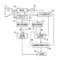
以下、本発明の実施の形態を図面に基づいて詳細に説明する。図2は、本発明が適用された動脈硬化検査装置10の回路構成を示すブロック図である。
【0018】
図2において、カフ12はゴム製袋を布製帯状袋内に有し、上腕部14に巻回される。カフ12には、圧力センサ16、調圧弁18が配管20を介してそれぞれ接続されている。また、調圧弁18には、配管22を介して空気ポンプ24が接続されている。調圧弁18は、空気ポンプ24により発生させられた圧力の高い空気を調圧してカフ12内へ供給し、或いは、カフ12内の空気を排気することにより、カフ12内の圧力を調圧する。
【0019】
圧力センサ16は、カフ12内の圧力を検出してその圧力を表す圧力信号SPを静圧弁別回路26および脈波弁別回路(すなわち脈波弁別装置)28にそれぞれ供給する。静圧弁別回路26はローパスフィルタを備えており、圧力信号SPに含まれる定常的な圧力すなわちカフ12の圧迫圧力(以下、この圧力をカフ圧PCという)を表すカフ圧信号SCを弁別してそのカフ圧信号SCをA/D変換器30を介して電子制御装置32へ供給する。脈波弁別回路28はバンドパスフィルタを備えており、圧力信号SPの振動成分であるカフ脈波信号SMを弁別してそのカフ脈波信号SMをA/D変換器34を介して電子制御装置32へ供給する。上記カフ脈波信号SMは、図示しない上腕動脈からカフ12に伝達される圧力振動であることから上腕脈波を表す。
【0020】
電子制御装置32は、CPU36、ROM38、RAM40、および図示しないI/Oポート等を備えた所謂マイクロコンピュータにて構成されており、CPU36は、ROM38に予め記憶されたプログラムに従ってRAM40の記憶機能を利用しつつ信号処理を実行することにより、I/Oポートから駆動信号を出力して空気ポンプ24および調圧弁18を制御する。CPU36は、その空気ポンプ24および調圧弁18を制御することによりカフ圧PCを制御する。また、CPU36は、図3に詳しく示す機能を実行することにより振幅増加指数AIを算出し、さらに、表示器42の表示内容を制御する。
【0021】
図3は、動脈硬化検査装置10における電子制御装置32の制御機能の要部を説明する機能ブロック線図である。
【0022】
カフ圧制御手段50は、静圧弁別回路26から供給されるカフ圧信号SCに基づいて調圧弁18および空気ポンプ24を制御して、カフ圧PCを制御する。従って、静圧弁別回路26、調圧弁18、空気ポンプ24およびカフ圧制御手段50によりカフ圧制御装置51が構成される。カフ圧制御手段50は、調圧弁18および空気ポンプ24を制御することにより、以下の血圧測定制御を実行する。すなわち、カフ圧制御手段50は、カフ圧PCを上腕部14における最高血圧値BPSYSよりも高い値に予め設定された昇圧目標圧力値(たとえば180mmHg)まで急速に昇圧し、その後、2〜3mmHg/secに設定された徐速降圧速度でカフ圧PCを徐速降圧させる。そして、次述する血圧値決定手段52により最低血圧値BPDIAが決定された後に、カフ圧PCを一拍分以上の間、その平均血圧値BPMEANまたは最低血圧値BPDIAに基づいて定まる脈波検出圧力値とする。この脈波検出圧力値は、カフ圧PCが最低血圧値BPDIAよりも高いと脈波弁別回路28によって弁別される上腕脈波に歪みが生じ、特に、平均血圧値BPMEANよりも高くなると上腕脈波の歪みが大きくなって、正確な振幅増加指数AIを算出することが困難になることから、平均血圧値BPMEANよりも低い値、好ましくは最低血圧値BPDIAよりも低い値に設定される。しかし、カフ圧PCが低すぎても弁別される上腕脈波が小さくなりすぎて正確な振幅増加指数AIを算出することが困難になるので、脈波検出圧力値は、上腕脈波の大きさが十分な大きさとなる程度に高い値に設定される。
【0023】
血圧値決定手段52は、カフ圧制御手段50によりカフ圧PCが徐速降圧させられる過程において、順次採取されるカフ脈波信号SMが表す上腕脈波の振幅の変化に基づき、よく知られたオシロメトリック法を用いて最高血圧値BPSYS・最低血圧値BPDIA・平均血圧値BPMEANを決定し、その決定した最高血圧値BPSYS等を表示器42に表示する。
【0024】
ピーク発生時決定手段54は、カフ圧制御手段50によりカフ圧PCが上腕部14における最高血圧値BPSYSよりも高い圧力において徐速降圧されている状態で、脈波弁別回路28により弁別される上腕脈波(以下、この上腕脈波を高圧時脈波という)について、進行波成分のピーク発生時点および反射波成分のピーク発生時点を決定する。図4は、図1の2つの脈波(頸動脈波および低圧時脈波)と、高圧時脈波とを立ち上がり点が一致するようにして並べて示す図であり、一点鎖線で示す波形が高圧時脈波である。図4(a)、(b)ともに、高圧時脈波には、2つのピークが観測でき、先に検出されるピーク発生時点は、頸動脈波から決定される進行波成分のピーク発生時点t1と一致し、後に検出されるピークは頸動脈波から決定される反射波成分のピーク発生時点t2と一致していることから、高圧時脈波の2つのピークのうち先に検出されるピークの発生時点を進行波成分のピーク発生時点に決定し、後に検出されるピークの発生時点を反射波成分のピーク発生時点に決定する。
【0025】
振幅増加指数算出手段56は、まず、ピーク発生時決定手段54により決定した高圧時脈波の進行波成分のピーク発生時および反射波成分のピーク発生時に基づいて、カフ圧制御手段50によりカフ圧PCが前記脈波検出圧力値とされている状態で脈波弁別回路28により弁別される上腕脈波すなわち低圧時脈波の進行波成分のピーク発生時点および反射波成分のピーク発生時点を決定する。すなわち、高圧時脈波の立ち上がり点の発生時点および低圧時脈波の立ち上がり点の発生時点を一致させた状態において、高圧時脈波の進行波成分のピーク発生時点および反射波成分のピーク発生時点を、低圧時脈波の進行波成分のピーク発生時点および反射波成分のピーク発生時点にそれぞれ決定する。さらに、低圧時脈波の脈圧PPを決定し、低圧時脈波の反射波成分のピーク発生時点における大きさbから進行波成分のピーク発生時点における大きさaを引いた差分値ΔP(=b−a)および脈圧PPから、式1に示す関係を用いて振幅増加指数AIを算出し、算出した振幅増加指数AIを表示器42に表示する。
(式1) AI=(ΔP/PP)×100 (%)
【0026】
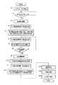
図5は、図3の機能ブロック線図に示したCPU36の制御作動をさらに具体的に説明したフローチャートである。
【0027】
図5において、まずステップS1(以下、ステップを省略する。)では、空気ポンプ24を起動させ、且つ、調圧弁18を制御することにより、カフ圧PCの急速昇圧を開始する。そして、S2では、カフ圧PCが180mmHgに設定された昇圧目標圧力値PCMを超えたか否かを判断する。このS2の判断が否定されるうちは、S2の判断を繰り返し実行し、カフ圧PCの急速昇圧を継続する。一方、S2の判断が肯定された場合には、S3において、空気ポンプ24を停止させ、且つ、調圧弁18を制御することにより、カフ圧PCの3mmHg/sec程度での徐速降圧を開始する。
【0028】
続くS4では、脈波弁別回路28から供給されるカフ脈波信号SMを一拍分読み込む。このS4で読み込んだカフ脈波信号SMは、徐速降圧開始当初に読み込むものであることから、カフ圧PCが最高血圧値BPSYSよりも高い圧力における上腕脈波すなわち高圧時脈波である。
【0029】
続くS5はピーク発生時決定手段54に相当し、S4で読み込んだ高圧時脈波の進行波成分のピーク発生時点および反射波成分のピーク発生時点を決定する。図4の一点鎖線で示すように、高圧時脈波は2つの極大点を示すことから、最初の極大点の発生時点を進行波成分のピーク発生時点に決定し、後の極大点の発生時点を反射波成分のピーク発生時点に決定する。
【0030】
続いて血圧値決定手段52に相当するS6乃至S9を実行する。S6は、前記S4と同様の処理であり、脈波弁別回路28から供給されるカフ脈波信号SMを一拍分読み込む。そして、続くS7は、カフ圧PCの徐速降圧過程で上記S6において逐次得られる上腕脈波の振幅の変化に基づいて、良く知られたオシロメトリック方式の血圧測定アルゴリズムに従って最高血圧値BPSYS、平均血圧値BPMEAN、および最低血圧値BPDIAを決定する。続くS8では、上記S7において血圧値BPの決定が完了したか否かを判断する。上記S7では、最低血圧値BPDIAが最後に決定されることから、S8では、最低血圧値BPDIAが決定されたか否かを判断する。このS8の判断が否定されるうちは、前記S6以下を繰り返し実行する。一方、S8の判断が肯定された場合には、S9において、S7で決定した最高血圧値BPSYS、平均血圧値BPMEAN、最低血圧値BPDIAを表示器42に表示する。
【0031】
続くS10では、カフ圧PCを、上記S7で決定した最低血圧値BPDIAから比較的小さい値に設定された所定値αを引くことにより脈波検出圧力値を算出し、カフ圧PCがその脈波検出圧力値まで降圧した時点で調圧弁18を制御することにより、カフ圧PCをその圧力に維持する。
【0032】
続くS11は、前記S4、S6と同様の処理であり、カフ圧PCが脈波検出圧力値に維持されている状態で、脈波弁別回路28から供給されるカフ脈波信号SMを一拍分読み込む。このS11で読み込んだカフ脈波信号SMは、カフ圧PCが最低血圧値BPDIAよりも小さい圧力において検出される脈波すなわち低圧時脈波である。
【0033】
続いて振幅増加指数算出手段56に相当するS12乃至S14を実行する。まず、S12では、S4で読み込んだ高圧時脈波の立ち上がり点を決定し、その立ち上がり点の発生時点からS5で決定した進行波成分のピーク発生時点までの第1期間およびその立ち上がり点の発生時点からS5で決定した反射波成分のピーク発生時点までの第2期間を算出する。さらに、S11で読み込んだ低圧時脈波の立ち上がり点を決定し、その低圧時脈波の立ち上がり点の発生時点から上記第1期間が経過した時点を低圧時脈波の進行波成分のピーク発生時点に決定し、その低圧時脈波の立ち上がり点から上記第2期間が経過した時点を低圧時脈波の反射波成分のピーク発生時点に決定する。このようにすると、図4に示すように、高圧時脈波の立ち上がり点と低圧時脈波の立ち上がり点とを一致させた状態において、高圧時脈波が示す進行波成分のピーク発生時点および反射波成分のピーク発生時点が、低圧時脈波においても進行波成分のピーク発生時点および反射波成分のピーク発生時点にそれぞれ決定される。
【0034】
続くS13では、低圧時脈波の脈圧PP、すなわちS11で読み込んだカフ脈波信号SMの最大値と最小値との差を算出する。そして、S14では、S12で決定した反射波成分のピーク発生時点における低圧時脈波の大きさbから進行波成分のピーク発生時点における低圧時脈波の大きさaを引いた差分値ΔPを算出し、さらに、その差分値ΔPおよびS13で算出した脈圧PPを前記式1に代入することにより振幅増加指数AIを算出し、その算出した振幅増加指数AIを表示器42に表示する。
【0035】
続くS15では、調圧弁18を制御することによりカフ圧PCを大気圧まで排圧する。
【0036】
上述のフローチャートに基づく実施例によれば、S5(ピーク発生時決定手段54)において、カフ圧PCが最高血圧値BPSYSよりも高い圧力において検出される上腕脈波から、進行波成分のピーク発生時点と反射波成分のピーク発生時点とが決定され、S12乃至S14(振幅増加指数算出手段56)では、S5(ピーク発生時決定手段54)で決定された進行波成分のピーク発生時点と反射波成分のピーク発生時点とに基づいて、低圧時脈波の進行波成分のピーク発生時と反射波成分のピーク発生時が決定されて、低圧時脈波から振幅増加指数AIが算出されるので、正確な振幅増加指数が算出される。
【0037】
また、上述のフローチャートに基づく実施例によれば、血圧測定のためにカフ圧PCが制御される際に高圧時脈波および低圧時脈波が得られ、その高圧時脈波および低圧時脈波から振幅増加指数AIが算出されるので、血圧測定と同時に振幅増加指数AIが得られる利点がある。
【0038】
以上、本発明の実施形態を図面に基づいて詳細に説明したが、本発明はその他の態様においても適用される。
【0039】
たとえば、前述の動脈硬化検査装置10では、カフ12は、上腕部14に装着されていたが、他の部位、たとえば大腿部や足首に装着されてもよい。
【0040】
また、前述の動脈硬化検査装置10は、カフ圧制御手段50により、カフ圧PCが最高血圧値BPSYSよりも高い圧力まで昇圧された直後に徐速降圧させられるようになっており、その徐速降圧過程で得られる上腕脈波を高圧時脈波として用いていた。一方、低圧時脈波には、カフ圧PCが脈波検出圧力値に維持されている状態で得られる上腕脈波を用いていた。しかし、カフ圧がPCが最高血圧値BPSYSよりも高い圧力で維持されるようになっており、その圧力維持状態で得られる上腕脈波を高圧時脈波として用いてもよい。また、低圧時脈波はカフ圧PCの徐速降圧過程で得られる上腕脈波を用いてもよい。
【0041】
また、前述の動脈硬化検査装置10では、カフ圧PCが予め設定された昇圧目標圧力値PCMから徐速降圧させられ始めた直後に得られる上腕脈波を、高圧時脈波として用いていることから、高圧時脈波を検出するときのカフ圧PCは予め決定されていたが、実際に最高血圧値BPSYSを測定し、その測定した最高血圧値BPSYSに基づいて高圧時脈波を検出するときのカフ圧PCが決定されてもよい。
一方、前述の動脈硬化検査装置10では、低圧時脈波を検出するときのカフ圧PCは実際に測定された血圧値BPに基づいて定められるようになっていたが、低圧時脈波を検出するときのカフ圧PCは予め設定された一定値または一定範囲であってもよい。
【0042】
また、振幅増加指数の算出式(式1)は、分母が脈圧PPであることが一般的であるが、分母が進行波成分のピーク発生時点または反射波成分のピーク発生時点における低圧時脈波の振幅であっても、算出される値は動脈硬化を反映するので、式1において脈圧PPに代えて進行波成分のピーク発生時点または反射波成分のピーク発生時点における低圧時脈波の振幅を用いてもよい。
【0043】
なお、本発明はその主旨を逸脱しない範囲において、その他種々の変更が加えられ得るものである。
【図面の簡単な説明】
【図1】異なる二人の患者からそれぞれ検出された頸動脈波と上腕脈波とを、立ち上がり点が一致するように並べて示す図である。
【図2】本発明の動脈硬化検査装置の回路構成を示すブロック図である。
【図3】図2の動脈硬化検査装置における電子制御装置の制御機能の要部を説明する機能ブロック線図である。
【図4】図1の頸動脈波および低圧時脈波に加えて、高圧時脈波を立ち上がり点が一致するようにして並べて示す図である。
【図5】図3の機能ブロック線図に示したCPUの制御作動をさらに具体的に説明するためのフローチャートである。
【符号の説明】
10:動脈硬化検査装置
12:カフ
28:脈波弁別回路(脈波弁別装置)
51:カフ圧制御装置
54:ピーク発生時決定手段
56:振幅増加指数算出手段[0001]
TECHNICAL FIELD OF THE INVENTION
The present invention relates to an amplitude increase index calculating device for calculating an amplitude increase index and an arteriosclerosis inspection device for inspecting arteriosclerosis based on the amplitude increase index.
[0002]
[Prior art]
The amplitude increase index is generally known as AI (= Augmentation Index), and represents a ratio of a reflected wave component to a traveling wave component of a pulse wave in order to evaluate aortic compliance. When the compliance of the aorta is large, the reflected wave component is small, and when the compliance is small, the reflected wave component is large. In other words, when the aortic blood vessel becomes hard, the reflected wave component of the aortic waveform becomes large. Therefore, the amplitude increase index reflects arteriosclerosis, and is used as an index for examining arteriosclerosis.
[0003]
As described above, the amplitude increase index is the ratio of the reflected wave component to the traveling wave component of the pulse wave. Separating a detected pulse wave (hereinafter referred to as a detected pulse wave) into a traveling wave component and a reflected wave component. Is difficult, the method of calculating the amplitude increase index determines the peak generation point of the traveling wave component and the peak generation point of the reflected wave component from the detected pulse wave, and determines the magnitude of the detected pulse wave when the peak of the traveling wave component occurs. And the magnitude of the detected pulse wave when the peak of the reflected wave component occurs is calculated by dividing the difference by the pulse pressure of the detected pulse wave. Further, the peak generation point of the traveling wave component is assumed to be the point of occurrence of the inflection point or the maximum point from the rising point to the peak of the detected pulse wave, and the peak generation point of the reflected wave component is after the peak of the traveling wave component. It is assumed that this is the time when the first maximum point occurs.
[0004]
[Problems to be solved by the invention]
As described above, the amplitude increase index evaluates the compliance of the aorta.In clinical practice, the amplitude increase index is calculated using the carotid artery wave closest to the aorta among the pulse waves that can be detected from the body surface. ing.
[0005]
However, a carotid artery wave sensor for detecting a carotid artery wave has a problem that skill is required to attach it to an appropriate position, and a measurement time is relatively long. Therefore, there has been a demand for calculating an amplitude increase index using a pulse wave that is easily detected, such as a brachial pulse wave.
[0006]
However, other than the carotid artery wave, it has been found that the peak generation point of the reflected wave component may not be the generation point of the first maximum point after the peak of the traveling wave component.
[0007]
FIG. 1 is a diagram showing carotid artery waves and brachial pulse waves simultaneously detected for two different patients, and the carotid artery waves and brachial pulse waves are arranged side by side so that the rising points coincide. The brachial pulse wave is a pulse wave that is discriminated from the pressure vibration transmitted to the cuff in a state where the compression pressure of the cuff is lower than the minimum blood pressure value (this pulse wave is referred to as a low-pressure pulse wave in the present specification). Which is the usual method for detecting an accurate waveform.
[0008]
In the case of the patient shown in FIG. 1A, the peak generation time t1 of the traveling wave component determined from the brachial pulse wave and the peak generation time t2 of the reflected wave component both coincide with those determined from the carotid artery wave. In many patients, the peak generation time of the traveling wave component and the peak generation time of the reflected wave component determined from the brachial pulse wave coincide with those determined from the carotid artery wave.
[0009]
On the other hand, also in the case of the patient shown in FIG. 1B, the peak occurrence time t1 of the traveling wave component determined from the brachial pulse wave coincides with the one determined from the carotid artery wave. However, assuming that the first maximum point after the peak of the traveling wave component is the peak generation point of the reflected wave component as before, the peak generation point t3 of the reflected wave component determined from the brachial pulse wave is determined from the carotid artery wave. It does not coincide with the peak occurrence time t2 of the reflected wave component. Therefore, in the case of the patient shown in FIG. 1B, the amplitude increase index calculated as before becomes inaccurate.
[0010]
The present invention has been made in view of the above circumstances, and an object of the present invention is to provide an amplitude increase index calculating device capable of more accurately calculating an amplitude increase index.
[0011]
[Means for Solving the Problems]
The present inventor has found that the pressure oscillation generated in the cuff when the cuff compression pressure is set to a pressure higher than the systolic blood pressure value shows two maximum values, as shown later by showing data, and 1 It has been found that the second maximum is the peak of the traveling wave component and the second maximum is the peak of the reflected wave component. If the peak generation time of the traveling wave component of the detected pulse wave and the peak generation time of the reflected wave component for calculating the amplitude increase index are determined using the generation points of the two local maxima, an accurate increase in the amplitude can be obtained. It was found that an index could be calculated. The present invention has been made based on such an idea.
[0012]
That is, the present invention for achieving the above object is based on a pulse wave detected from a living body, and calculates an amplitude increase index indicating a ratio of a reflected wave component of the pulse wave to a traveling wave component of the pulse wave. (A) a cuff attached to a predetermined portion of the living body, (b) a cuff pressure control device for controlling a compression pressure of the cuff, and (c) a cuff from the living body. A pulse wave discrimination device for discriminating a pulse wave from pressure vibration transmitted to the cuff, and (d) a state in which the cuff pressure control device sets the compression pressure of the cuff at a pressure higher than the systolic blood pressure value at the cuff mounting site. Based on the high-pressure pulse wave discriminated by the pulse-wave discriminating apparatus, a peak generation that determines when the peak of the traveling-wave component of the high-pressure pulse wave and when the peak of the reflected-wave component of the high-pressure pulse wave occurs. Time determining means and (e) before Peak occurrence of a traveling wave component in a low-pressure pulse wave discriminated by the pulse wave discriminator in a state where the cuff pressure control device sets the compression pressure of the cuff at a pressure lower than the average blood pressure value at the cuff mounting portion. And the peak occurrence time of the reflected wave component is determined based on the peak occurrence time of the traveling wave component of the high pressure pulse wave and the peak occurrence time of the reflected wave component determined by the peak occurrence time determination means. Amplitude increasing index calculating means for calculating the amplitude increasing index based on the magnitude of the traveling wave component of the wave at the peak occurrence time and the magnitude of the reflected wave component at the peak occurrence time.
[0013]
【The invention's effect】
According to the present invention, the peak occurrence time determining means determines the peak occurrence time of the traveling wave component and the peak occurrence time of the reflected wave component from the pulse wave detected when the compression pressure of the cuff is higher than the systolic blood pressure value. The amplitude increase index calculating means determines the peak of the traveling wave component of the pulse wave at low pressure based on the peak occurrence time of the traveling wave component and the peak occurrence time of the reflected wave component determined by the peak occurrence determining means. The time and the peak occurrence time of the reflected wave component are determined, and the amplitude increase index is calculated from the low pressure pulse wave, so that the accurate amplitude increase index is calculated.
[0014]
Other aspects of the invention
The cuff is attached to, for example, an upper arm. When the cuff is worn on the upper arm, the pulse wave discriminated by the pulse wave discriminator becomes a pulse wave from the artery of the upper arm. It becomes the amplitude increase index of the wave.
[0015]
Also, preferably, the cuff pressure control device gradually reduces the compression pressure of the cuff from a pressure higher than the systolic blood pressure of the portion where the cuff is mounted to a pressure lower than the diastolic blood pressure for blood pressure measurement. A blood pressure measurement control including a rapid pressure drop process is performed, and the high pressure pulse wave is a state in which the cuff pressure is set to a pressure higher than a systolic blood pressure in the blood pressure measurement control process by the cuff pressure control device. In the pulse wave discriminated by the pulse wave discriminating device, the low pressure pulse wave is a state where the cuff pressure is lower than the diastolic blood pressure in the blood pressure measurement control process by the cuff pressure control device. Is a pulse wave discriminated by the pulse wave discriminating apparatus.
In this way, when the compression pressure of the cuff is controlled for measuring blood pressure, a high-pressure pulse wave and a low-pressure pulse wave are obtained, and an amplitude increase index is calculated from the high-pressure pulse wave and the low-pressure pulse wave. Therefore, there is an advantage that the amplitude increase index can be obtained simultaneously with the blood pressure measurement.
[0016]
The amplitude increase index calculating device can be used as an arteriosclerosis test device. That is, the arterial stiffness test device tests the arteriosclerosis of the living body based on the amplitude increase index calculated by the amplitude increase index calculation device.
[0017]
BEST MODE FOR CARRYING OUT THE INVENTION
Hereinafter, embodiments of the present invention will be described in detail with reference to the drawings. FIG. 2 is a block diagram showing a circuit configuration of the
[0018]
In FIG. 2, the
[0019]
The
[0020]
The
[0021]
FIG. 3 is a functional block diagram for explaining a main part of a control function of the
[0022]
The cuff pressure control means 50 controls the
[0023]
The blood pressure
[0024]
The peak occurrence determination means 54 is discriminated by the pulse
[0025]
First, the cuff pressure control means 50 controls the cuff pressure based on the time when the peak of the traveling wave component of the high-pressure pulse wave and the time when the peak of the reflected wave component occur, which are determined by the peak occurrence determination means 54. With the PC set to the pulse wave detection pressure value, the peak generation point of the traveling wave component and the peak generation point of the reflected wave component of the brachial pulse wave, that is, the pulse wave at low pressure, which are discriminated by the pulse
(Equation 1) AI = (ΔP / PP) × 100 (%)
[0026]
FIG. 5 is a flowchart illustrating the control operation of the
[0027]
In FIG. 5, first, in step S1 (hereinafter, steps are omitted), the
[0028]
In the following S4, the cuff pulse wave signal SM supplied from the pulse
[0029]
Subsequent S5 corresponds to the peak generation
[0030]
Subsequently, S6 to S9 corresponding to the blood pressure
[0031]
In subsequent S10, the cuff pressure PC is calculated by subtracting a predetermined value α set to a relatively small value from the diastolic blood pressure value BPDIA determined in S7, and a pulse wave detection pressure value is calculated. The cuff pressure PC is maintained at that pressure by controlling the
[0032]
Subsequent S11 is a process similar to the above S4 and S6. In the state where the cuff pressure PC is maintained at the pulse wave detection pressure value, the cuff pulse wave signal SM supplied from the pulse
[0033]
Subsequently, S12 to S14 corresponding to the amplitude increase index calculating means 56 are executed. First, in S12, the rising point of the high-pressure pulse wave read in S4 is determined, and the first period from the generation point of the rising point to the peak generation point of the traveling wave component determined in S5 and the generation point of the rising point , A second period from when the peak of the reflected wave component determined in S5 occurs is calculated. Further, the rising point of the low-pressure pulse wave read in S11 is determined, and the point in time when the first period has elapsed from the point of occurrence of the rising point of the low-pressure pulse wave is determined as the peak generation point of the traveling wave component of the low-pressure pulse wave. And the point in time when the second period has elapsed from the rising point of the low-pressure pulse wave is determined as the peak generation point of the reflected wave component of the low-pressure pulse wave. In this way, as shown in FIG. 4, when the rising point of the high-pressure pulse wave coincides with the rising point of the low-pressure pulse wave, the peak generation time and reflection of the traveling wave component indicated by the high-pressure pulse wave are obtained. The peak occurrence time of the wave component is determined as the peak generation time of the traveling wave component and the peak occurrence time of the reflected wave component even in the low pressure pulse wave.
[0034]
In the following S13, the pulse pressure PP of the low-pressure pulse wave, that is, the difference between the maximum value and the minimum value of the cuff pulse wave signal SM read in S11 is calculated. Then, in S14, a difference value ΔP is calculated by subtracting the magnitude b of the low-pressure pulse wave at the time of occurrence of the peak of the traveling wave component from the magnitude b of the low-pressure pulse wave at the time of occurrence of the peak of the reflected wave component determined in S12. Then, the amplitude increase index AI is calculated by substituting the difference value ΔP and the pulse pressure PP calculated in S13 into the
[0035]
In subsequent S15, the cuff pressure PC is exhausted to the atmospheric pressure by controlling the
[0036]
According to the embodiment based on the above-described flowchart, in S5 (peak occurrence determination means 54), the peak of the traveling wave component is generated from the brachial pulse wave detected at a pressure where the cuff pressure PC is higher than the systolic blood pressure value BPSYS. The time point and the peak occurrence time of the reflected wave component are determined. In S12 to S14 (amplitude increase index calculating means 56), the peak occurrence time of the traveling wave component and the reflected wave determined in S5 (peak occurrence time determination means 54) are determined. Based on the peak occurrence time of the component, the peak occurrence time of the traveling wave component and the peak occurrence time of the reflected wave component of the low pressure pulse wave are determined, and the amplitude increase index AI is calculated from the low pressure pulse wave, An accurate amplitude increase index is calculated.
[0037]
Further, according to the embodiment based on the above-described flowchart, when the cuff pressure PC is controlled for measuring the blood pressure, a high-pressure pulse wave and a low-pressure pulse wave are obtained, and the high-pressure pulse wave and the low-pressure pulse wave are obtained. Since the amplitude increase index AI is calculated from the above, there is an advantage that the amplitude increase index AI can be obtained simultaneously with the blood pressure measurement.
[0038]
Although the embodiments of the present invention have been described in detail with reference to the drawings, the present invention is applicable to other aspects.
[0039]
For example, in the
[0040]
In the
[0041]
Also, the
On the other hand, in the
[0042]
In general, the equation for calculating the amplitude increase index (Equation 1) is that the denominator is the pulse pressure PP, but the denominator is the low-pressure pulse at the time of occurrence of the peak of the traveling wave component or the time of occurrence of the peak of the reflected wave component. Even if it is the amplitude of the wave, since the calculated value reflects arteriosclerosis, the pulse pressure of the low pressure pulse wave at the time when the peak of the traveling wave component or the time when the peak of the reflected wave component occurs in place of the pulse pressure PP in Equation (1). The amplitude may be used.
[0043]
The present invention can be modified in various other ways without departing from the gist of the invention.
[Brief description of the drawings]
FIG. 1 is a diagram showing carotid artery waves and brachial pulse waves detected from two different patients, respectively, arranged so that rising points coincide.
FIG. 2 is a block diagram showing a circuit configuration of the arteriosclerosis testing apparatus of the present invention.
FIG. 3 is a functional block diagram illustrating a main part of a control function of an electronic control device in the arteriosclerosis test apparatus of FIG. 2;
FIG. 4 is a diagram showing, in addition to the carotid artery wave and the low pressure pulse wave in FIG. 1, a high pressure pulse wave arranged side by side so that rising points coincide.
FIG. 5 is a flowchart for more specifically explaining the control operation of the CPU shown in the functional block diagram of FIG. 3;
[Explanation of symbols]
10: Arteriosclerosis testing device 12: Cuff 28: Pulse wave discrimination circuit (pulse wave discrimination device)
51: Cuff pressure control device 54: Peak occurrence determination means 56: Amplitude increase index calculation means
Claims (4)
Translated fromJapanese前記生体の所定部位に装着されるカフと、
該カフの圧迫圧力を制御するカフ圧制御装置と、
前記生体から前記カフに伝達する圧力振動から脈波を弁別する脈波弁別装置と、
前記カフ圧制御装置により前記カフの圧迫圧力が該カフの装着部位における最高血圧値よりも高い圧力とされている状態で前記脈波弁別装置により弁別される高圧時脈波に基づいて、該高圧時脈波の進行波成分のピーク発生時と該高圧時脈波の反射波成分のピーク発生時を決定するピーク発生時決定手段と、
前記カフ圧制御装置により前記カフの圧迫圧力が該カフの装着部位における平均血圧値よりも低い圧力とされている状態で前記脈波弁別装置により弁別される低圧時脈波における進行波成分のピーク発生時および反射波成分のピーク発生時を、前記ピーク発生時決定手段により決定された高圧時脈波の進行波成分のピーク発生時と反射波成分のピーク発生時に基づいて決定し、該低圧時脈波の進行波成分のピーク発生時点における大きさと反射波成分のピーク発生時点における大きさとに基づいて、前記振幅増加指数を算出する振幅増加指数算出手段と
を含むことを特徴とする振幅増加指数算出装置。An amplitude increase index calculating device for calculating an amplitude increase index representing a ratio of a reflected wave component of the pulse wave to a traveling wave component of the pulse wave based on the pulse wave detected from the living body,
A cuff attached to a predetermined part of the living body,
A cuff pressure control device for controlling the compression pressure of the cuff,
A pulse wave discrimination device that discriminates a pulse wave from pressure vibration transmitted from the living body to the cuff,
The cuff pressure control device sets the compression pressure of the cuff at a pressure higher than the systolic blood pressure value at the cuff mounting site, and based on the high-pressure pulse wave discriminated by the pulse wave discrimination device, Peak generation time determining means for determining the peak generation of the traveling wave component of the time pulse wave and the peak generation of the reflected wave component of the high pressure pulse wave,
The peak of the traveling wave component in the low-pressure pulse wave discriminated by the pulse wave discrimination device in a state where the cuff pressure control device sets the compression pressure of the cuff at a pressure lower than the average blood pressure value at the cuff wearing site. The time of occurrence and the time of occurrence of the peak of the reflected wave component are determined based on the time of occurrence of the peak of the traveling wave component of the high pressure pulse wave and the time of occurrence of the peak of the reflected wave component determined by the peak occurrence time determination means. Amplitude increase index calculating means for calculating the amplitude increase index based on the magnitude of the traveling wave component of the pulse wave at the peak occurrence time and the magnitude of the reflected wave component at the peak occurrence time. Calculation device.
前記振幅増加指数は該上腕の動脈における脈波の振幅増加指数である請求項1の振幅増加指数算出装置。The cuff is mounted on the upper arm,
2. The amplitude increase index calculating device according to claim 1, wherein the amplitude increase index is an amplitude increase index of a pulse wave in the artery of the upper arm.
前記高圧時脈波は、前記カフ圧制御装置による血圧測定制御過程において前記カフの圧迫圧力が最高血圧よりも高い圧力とされている状態で前記脈波弁別装置により弁別される脈波であり、
前記低圧時脈波は、前記カフ圧制御装置による血圧測定制御過程において前記カフの圧迫圧力が最低血圧よりも低い圧力とされている状態で前記脈波弁別装置により弁別される脈波であることを特徴とする請求項1または2の振幅増加指数算出装置。The cuff pressure control device includes a slow pressure step of gradually lowering the compression pressure of the cuff from a pressure higher than the systolic blood pressure of the portion where the cuff is mounted to a pressure lower than the diastolic blood pressure for measuring the blood pressure. To execute blood pressure measurement control,
The high pressure pulse wave is a pulse wave that is discriminated by the pulse wave discrimination device in a state where the cuff pressure is set to a pressure higher than the systolic blood pressure in the blood pressure measurement control process by the cuff pressure control device,
The low pressure pulse wave is a pulse wave that is discriminated by the pulse wave discrimination device in a state where the cuff compression pressure is lower than the minimum blood pressure in the blood pressure measurement control process by the cuff pressure control device. The apparatus for calculating an amplitude increase index according to claim 1 or 2, wherein:
Priority Applications (6)
| Application Number | Priority Date | Filing Date | Title |
|---|---|---|---|
| JP2002003403AJP3590613B2 (en) | 2002-01-10 | 2002-01-10 | Amplitude increase index calculation device and arteriosclerosis test device |
| US10/237,099US6712768B2 (en) | 2002-01-10 | 2002-09-09 | Augmentation-index determining apparatus and arteriosclerosis inspecting apparatus |
| EP02020450AEP1340453A3 (en) | 2002-01-10 | 2002-09-11 | Augmentation-index determining apparatus and arteriosclerosis inspecting apparatus |
| TW091121978ATW534807B (en) | 2002-01-10 | 2002-09-25 | Augmentation-index determining apparatus and arteriosclerosis inspecting apparatus |
| KR1020020061468AKR100865050B1 (en) | 2002-01-10 | 2002-10-09 | Amplitude increase index determination device and arteriosclerosis inspection device |
| CNB021475768ACN1292704C (en) | 2002-01-10 | 2002-10-15 | Increment index determining equipment and arteriosclerosis checking equipment |
Applications Claiming Priority (1)
| Application Number | Priority Date | Filing Date | Title |
|---|---|---|---|
| JP2002003403AJP3590613B2 (en) | 2002-01-10 | 2002-01-10 | Amplitude increase index calculation device and arteriosclerosis test device |
Publications (2)
| Publication Number | Publication Date |
|---|---|
| JP2003204945A JP2003204945A (en) | 2003-07-22 |
| JP3590613B2true JP3590613B2 (en) | 2004-11-17 |
Family
ID=19190874
Family Applications (1)
| Application Number | Title | Priority Date | Filing Date |
|---|---|---|---|
| JP2002003403AExpired - LifetimeJP3590613B2 (en) | 2002-01-10 | 2002-01-10 | Amplitude increase index calculation device and arteriosclerosis test device |
Country Status (6)
| Country | Link |
|---|---|
| US (1) | US6712768B2 (en) |
| EP (1) | EP1340453A3 (en) |
| JP (1) | JP3590613B2 (en) |
| KR (1) | KR100865050B1 (en) |
| CN (1) | CN1292704C (en) |
| TW (1) | TW534807B (en) |
Families Citing this family (23)
| Publication number | Priority date | Publication date | Assignee | Title |
|---|---|---|---|---|
| JP2003305011A (en) | 2002-04-17 | 2003-10-28 | Nippon Colin Co Ltd | Amplitude augmentation index measuring apparatus |
| JP3649703B2 (en)* | 2002-04-17 | 2005-05-18 | コーリンメディカルテクノロジー株式会社 | Blood pressure measurement device with amplitude increase index measurement function |
| JP3621395B2 (en)* | 2002-04-17 | 2005-02-16 | コーリンメディカルテクノロジー株式会社 | Blood pressure measurement device with waveform analysis function |
| JP2004016746A (en)* | 2002-06-20 | 2004-01-22 | Nippon Colin Co Ltd | Circulatory dynamics evaluation device |
| JP4590844B2 (en)* | 2003-08-26 | 2010-12-01 | パナソニック電工株式会社 | Cardiovascular function judgment device |
| HU0400426D0 (en)* | 2004-02-18 | 2004-04-28 | Illyes Miklos Dr | Apparatus and method for measurement of dynamic characteristic of blood and for complex monitoring of circulatory system |
| BRPI0506434A (en)* | 2004-02-18 | 2006-12-26 | Jozsef Beres | apparatus and method for measuring hemodynamic parameters |
| US20090312653A1 (en)* | 2008-06-16 | 2009-12-17 | Sharrock Nigel E | Method and apparatus for determining cardiac medical parameters from supra-systolicsignals obtained from an oscillometric blood pressure system |
| US9433358B2 (en)* | 2006-02-21 | 2016-09-06 | Uscom Ltd. | Method and apparatus for producing a central pressure waveform in an oscillometric blood pressure system |
| JP5530073B2 (en)* | 2008-03-26 | 2014-06-25 | フクダ電子株式会社 | Blood pressure pulse wave inspection device |
| JP2011520502A (en)* | 2008-05-15 | 2011-07-21 | パルスコー リミテッド | Estimation method of central pressure waveform obtained using blood pressure cuff |
| WO2010024418A1 (en)* | 2008-09-01 | 2010-03-04 | 学校法人同志社 | Arteriosclerosis evaluating apparatus |
| CA2738976A1 (en)* | 2008-10-01 | 2010-04-08 | Irumedi Co., Ltd. | Cardiovascular analyzer |
| US8840561B2 (en)* | 2009-12-31 | 2014-09-23 | Welch Allyn, Inc. | Suprasystolic measurement in a fast blood-pressure cycle |
| JP5493932B2 (en) | 2010-02-02 | 2014-05-14 | オムロンヘルスケア株式会社 | Blood pressure information measuring device |
| JP5504477B2 (en)* | 2010-03-16 | 2014-05-28 | 国立大学法人富山大学 | Fingertip pulse wave analyzer and vascular endothelial function evaluation system using the same |
| US8197414B2 (en) | 2010-05-25 | 2012-06-12 | Welch Allyn, Inc. | Systems and methods for measuring arterial stiffness |
| JP5584077B2 (en)* | 2010-09-29 | 2014-09-03 | 株式会社エー・アンド・デイ | Automatic blood pressure measurement device |
| DE112011104312B4 (en)* | 2010-12-08 | 2024-07-18 | Omron Healthcare Co., Ltd. | Blood pressure information measuring device and method for calculating the index of the degree of arteriosclerosis using this device |
| JP5568151B2 (en)* | 2013-03-08 | 2014-08-06 | フクダ電子株式会社 | Blood pressure pulse wave inspection device |
| JP5752162B2 (en)* | 2013-03-08 | 2015-07-22 | フクダ電子株式会社 | Blood pressure pulse wave inspection device |
| US10058255B2 (en)* | 2014-05-29 | 2018-08-28 | Hong Kong Applied Science And Technology Research Institute Co. Ltd. | Method of determining stiffness index of an arterial network and system thereof |
| KR101919141B1 (en) | 2017-08-25 | 2019-02-08 | (주)참케어 | Optical sensor based blood pressure measuring device |
Family Cites Families (6)
| Publication number | Priority date | Publication date | Assignee | Title |
|---|---|---|---|---|
| WO1990011043A1 (en) | 1989-03-24 | 1990-10-04 | Eastern Medical Testing Services, Inc. | A method and apparatus for ascertaining the contour of the pressure pulse in the central arteries from the contour of the pressure pulse in the peripheral arteries |
| US5265011A (en)* | 1989-04-03 | 1993-11-23 | Eastern Medical Testing Services, Inc. | Method for ascertaining the pressure pulse and related parameters in the ascending aorta from the contour of the pressure pulse in the peripheral arteries |
| US5797850A (en)* | 1993-11-09 | 1998-08-25 | Medwave, Inc. | Method and apparatus for calculating blood pressure of an artery |
| CN1121798A (en)* | 1994-08-16 | 1996-05-08 | 北京工业大学 | Cardiovascular function dynamic parameter testing analysis method and apparatus |
| US5860932A (en) | 1996-10-24 | 1999-01-19 | Colin Corporation | Blood pressure monitor |
| JP3533406B2 (en)* | 2001-07-02 | 2004-05-31 | コーリンメディカルテクノロジー株式会社 | Atherosclerosis evaluation device |
- 2002
- 2002-01-10JPJP2002003403Apatent/JP3590613B2/ennot_activeExpired - Lifetime
- 2002-09-09USUS10/237,099patent/US6712768B2/ennot_activeExpired - Lifetime
- 2002-09-11EPEP02020450Apatent/EP1340453A3/ennot_activeWithdrawn
- 2002-09-25TWTW091121978Apatent/TW534807B/ennot_activeIP Right Cessation
- 2002-10-09KRKR1020020061468Apatent/KR100865050B1/ennot_activeExpired - Lifetime
- 2002-10-15CNCNB021475768Apatent/CN1292704C/ennot_activeExpired - Lifetime
Also Published As
| Publication number | Publication date |
|---|---|
| KR100865050B1 (en) | 2008-10-23 |
| CN1292704C (en) | 2007-01-03 |
| US20030130583A1 (en) | 2003-07-10 |
| CN1432339A (en) | 2003-07-30 |
| KR20030061290A (en) | 2003-07-18 |
| TW534807B (en) | 2003-06-01 |
| EP1340453A3 (en) | 2003-09-24 |
| US6712768B2 (en) | 2004-03-30 |
| JP2003204945A (en) | 2003-07-22 |
| EP1340453A2 (en) | 2003-09-03 |
Similar Documents
| Publication | Publication Date | Title |
|---|---|---|
| JP3590613B2 (en) | Amplitude increase index calculation device and arteriosclerosis test device | |
| JP3643567B2 (en) | Amplitude increase index measuring device | |
| JP3587837B2 (en) | Arterial stiffness evaluation device | |
| JP3774396B2 (en) | Oscillometric automatic blood pressure measuring device | |
| JP2002272688A (en) | Ankle-brachial blood pressure index measuring apparatus | |
| JPH08215156A (en) | Peripheral circulating condition-monitoring device | |
| JP2004016745A (en) | Blood pressure determining apparatus | |
| JP2000135202A (en) | Blood pressure moitoring device | |
| JP3530891B2 (en) | Blood pressure determination device | |
| JPH08280640A (en) | Automatic blood pressure measuring device and blood pressuresupervision method for patient | |
| JP3638907B2 (en) | Lower limb upper limb blood pressure index measuring device | |
| JP3649703B2 (en) | Blood pressure measurement device with amplitude increase index measurement function | |
| JP2002360526A (en) | Sphygmomanometry system with cardiac function evaluating function | |
| JP2004105550A (en) | Arteriostenosis examination apparatus | |
| JP2003235816A (en) | Pressure pulse wave detector | |
| JP3621395B2 (en) | Blood pressure measurement device with waveform analysis function | |
| JP2003305011A (en) | Amplitude augmentation index measuring apparatus | |
| JP2003199718A (en) | Arterial sclerosis evaluation apparatus | |
| JP2003116800A (en) | Waveform characteristic point determining device and pulse wave propagation velocity information measuring device using this waveform characteristic point determining device | |
| JP2004261321A (en) | Blood flow rate estimation device | |
| JPS61122840A (en) | Method and apparatus for controlling cuff pressure | |
| JPH0538332A (en) | Device for measuring degree of arteriosclerosis | |
| JPH08256999A (en) | Living body information monitoring device | |
| JP3002595B2 (en) | Blood pressure monitoring device | |
| JP2006247216A (en) | Automated oscillometric blood pressure-measuring apparatus |
Legal Events
| Date | Code | Title | Description |
|---|---|---|---|
| A711 | Notification of change in applicant | Free format text:JAPANESE INTERMEDIATE CODE: A711 Effective date:20040119 | |
| A521 | Request for written amendment filed | Free format text:JAPANESE INTERMEDIATE CODE: A523 Effective date:20040225 | |
| A977 | Report on retrieval | Free format text:JAPANESE INTERMEDIATE CODE: A971007 Effective date:20040714 | |
| TRDD | Decision of grant or rejection written | ||
| A01 | Written decision to grant a patent or to grant a registration (utility model) | Free format text:JAPANESE INTERMEDIATE CODE: A01 Effective date:20040817 | |
| A61 | First payment of annual fees (during grant procedure) | Free format text:JAPANESE INTERMEDIATE CODE: A61 Effective date:20040820 | |
| R150 | Certificate of patent or registration of utility model | Free format text:JAPANESE INTERMEDIATE CODE: R150 Ref document number:3590613 Country of ref document:JP Free format text:JAPANESE INTERMEDIATE CODE: R150 | |
| S111 | Request for change of ownership or part of ownership | Free format text:JAPANESE INTERMEDIATE CODE: R313113 | |
| R350 | Written notification of registration of transfer | Free format text:JAPANESE INTERMEDIATE CODE: R350 | |
| FPAY | Renewal fee payment (event date is renewal date of database) | Free format text:PAYMENT UNTIL: 20080827 Year of fee payment:4 | |
| FPAY | Renewal fee payment (event date is renewal date of database) | Free format text:PAYMENT UNTIL: 20090827 Year of fee payment:5 | |
| FPAY | Renewal fee payment (event date is renewal date of database) | Free format text:PAYMENT UNTIL: 20100827 Year of fee payment:6 | |
| FPAY | Renewal fee payment (event date is renewal date of database) | Free format text:PAYMENT UNTIL: 20100827 Year of fee payment:6 | |
| FPAY | Renewal fee payment (event date is renewal date of database) | Free format text:PAYMENT UNTIL: 20110827 Year of fee payment:7 | |
| FPAY | Renewal fee payment (event date is renewal date of database) | Free format text:PAYMENT UNTIL: 20110827 Year of fee payment:7 | |
| FPAY | Renewal fee payment (event date is renewal date of database) | Free format text:PAYMENT UNTIL: 20120827 Year of fee payment:8 | |
| FPAY | Renewal fee payment (event date is renewal date of database) | Free format text:PAYMENT UNTIL: 20130827 Year of fee payment:9 | |
| S531 | Written request for registration of change of domicile | Free format text:JAPANESE INTERMEDIATE CODE: R313531 | |
| R350 | Written notification of registration of transfer | Free format text:JAPANESE INTERMEDIATE CODE: R350 | |
| S111 | Request for change of ownership or part of ownership | Free format text:JAPANESE INTERMEDIATE CODE: R313113 | |
| R350 | Written notification of registration of transfer | Free format text:JAPANESE INTERMEDIATE CODE: R350 | |
| R250 | Receipt of annual fees | Free format text:JAPANESE INTERMEDIATE CODE: R250 | |
| R250 | Receipt of annual fees | Free format text:JAPANESE INTERMEDIATE CODE: R250 | |
| R250 | Receipt of annual fees | Free format text:JAPANESE INTERMEDIATE CODE: R250 | |
| R250 | Receipt of annual fees | Free format text:JAPANESE INTERMEDIATE CODE: R250 | |
| EXPY | Cancellation because of completion of term |