JP3590519B2 - Sounding device - Google Patents
Sounding deviceDownload PDFInfo
- Publication number
- JP3590519B2 JP3590519B2JP01971598AJP1971598AJP3590519B2JP 3590519 B2JP3590519 B2JP 3590519B2JP 01971598 AJP01971598 AJP 01971598AJP 1971598 AJP1971598 AJP 1971598AJP 3590519 B2JP3590519 B2JP 3590519B2
- Authority
- JP
- Japan
- Prior art keywords
- sounding
- solenoid
- generating device
- sound generating
- sounding body
- Prior art date
- Legal status (The legal status is an assumption and is not a legal conclusion. Google has not performed a legal analysis and makes no representation as to the accuracy of the status listed.)
- Expired - Fee Related
Links
- 230000007246mechanismEffects0.000description18
- 230000001965increasing effectEffects0.000description14
- 238000009434installationMethods0.000description13
- 230000000694effectsEffects0.000description11
- 230000003116impacting effectEffects0.000description5
- NJPPVKZQTLUDBO-UHFFFAOYSA-NnovaluronChemical compoundC1=C(Cl)C(OC(F)(F)C(OC(F)(F)F)F)=CC=C1NC(=O)NC(=O)C1=C(F)C=CC=C1FNJPPVKZQTLUDBO-UHFFFAOYSA-N0.000description4
- 230000009467reductionEffects0.000description4
- 230000008859changeEffects0.000description3
- 230000003247decreasing effectEffects0.000description3
- 239000000463materialSubstances0.000description3
- 238000000034methodMethods0.000description2
- 229910001018Cast ironInorganic materials0.000description1
- 230000004913activationEffects0.000description1
- 210000000078clawAnatomy0.000description1
- 238000005034decorationMethods0.000description1
- 230000002708enhancing effectEffects0.000description1
- 239000000696magnetic materialSubstances0.000description1
- 238000004519manufacturing processMethods0.000description1
- 239000002184metalSubstances0.000description1
- 229910052751metalInorganic materials0.000description1
- 239000007769metal materialSubstances0.000description1
- 230000002093peripheral effectEffects0.000description1
- 230000004044responseEffects0.000description1
Images


Landscapes
- Electrophonic Musical Instruments (AREA)
- Toys (AREA)
Description
Translated fromJapanese【0001】
【発明の属する技術分野】
本発明は、オルゴール、チャイム及び時計の時報機構等に好適な発音装置に関する。
【0002】
【従来の技術】
一般に、時計等の報知に用いられる発音手段としては、発音回路及びスピーカ等を用いて、人工的な電子音を得るものに限らず、機械的な発音装置を用いて、情趣に富む柔らかな発音や、該発音による曲目を演奏するものが知られている。
【0003】
すなわち、電子音によるものでは、音色を自由に設定できるが、あくまでも擬似的な音色しか得ることができず、高級感に富み臨場感にあふれた生の演奏音を得ることはできない。
【0004】
この種の発音装置は、所定音階且つ音色を発生する金属製の発音体を設置し、この発音体の発音部分を、各種の機構により、打撃したり、弾くように構成され、演奏曲目を固定設置的なシリンダーや、交換可能なディスクに記録したものがある。
【0005】
このシリンダー・タイプの発音装置は、所定直径且つ長さの円筒状に形成されたシリンダーの外周に、発音体の発音部分に対応し、且つ曲目の発音タイミングの位置にピン状の突起を形成するとともに、このシリンダーを、発音体に対峙させて、回転駆動を可能に設けて構成され、このシリンダーを回転駆動すると、シリンダーの各突起が、発音体の各発音部位を直接的に爪弾いて、所定の曲目を演奏するようにしている。
【0006】
また、ディスク・タイプは、所定直径の薄円板状に形成されたディスクの表面に、発音体の発音部分に応じて複数トラックに区画し、そのトラックが分担した音階の発音タイミングに応じた周方向の箇所に、突起や所定径の孔状の演奏用係合部を形成するとともに、このディスクを、発音体に対面させて、回転駆動を可能に設けて構成され、このディスクを回転駆動すると、ディスクの各係合部が、星車を介して、発音体の各発音部位を間接的に爪弾いて、所定の曲目を演奏するようにしている。
【0007】
尚、このディスク・タイプにおいては、ディスクを交換可能に設け、人手やオートチェンジ機構により、複数ディスクによる複数曲目を演奏できるようにしたものが各種提案されている。
【0008】
【発明が解決しようとする課題】
ところが、上記従来のシリンダやディスク・タイプの発音装置においては、その演奏する曲目数や演奏時間、発音装置を設置するスペース等の点で、以下のような問題点を生じていた。
【0009】
すなわち、曲目数に関して、シリンダ・タイプでは、その長手方向を延在させて、延長した各ブロックに複数曲目を記録し、シリンダをスライド移動させて、複数曲目から択一的に選択する構成が考えられるが、機構の複雑化による物理的な設置スペースや、信頼性、コスト的な面で不利である。
【0010】
また、ディスク・タイプにおいては、上述したように複数の交換ディスクを用いて、複数曲目を選択可能にできるが、人手の場合には、交換の手間がかかり、自動化した場合にも、シリンダ・タイプと同様に、設置スペースや、信頼性、コスト的な面で不利である。
【0011】
更に、演奏時間に関しては、シリンダ及びディスクの両方とも、基本的に、その1回転動作で1曲目であり、この演奏時間を変えるために回転スピードを増減することは、曲調や音色等が変わってしまい好ましくないので、演奏時間は、常に一定である。また、これらを回避して演奏時間を延長するために、シリンダやディスクを大型化すると、これに伴って、装置自体が大掛かりとなってしまい、重量やスペース、コストで不利であり、小規模な用途に使えないことになる。
【0012】
また、シリンダやディスク・タイプにおいて、その機械的な演奏情報を記録したシリンダ外周やディスク表面の記録面における情報密度は、物理的及び実際的な制約から低く、小型化を図ることが困難で、設置スペースの利用効率が、あまり良くないという不都合がある。すなわち、記録体の外面に設けた突起等の係合部を、機械的な駆動源として発音動作させているので、同一音階の係合部同士における最小限の間隙距離は、物理的に自ずから決まっており、更には製作誤差や高精度コスト等の面からも、記録面の情報密度を高めることは困難である。
【0013】
特に、ディスク・タイプにおいては、最小限度、円板状のディスクを安定して回転させるスペースが必要であり、また、ディスク交換可能に構成した場合には、外部からディスクを入れてセットするまでに至る経路スペースを確保したり、ディスク交換しやすい箇所に、その設置箇所が限定されたりするので、スペース利用効率が低下する傾向が、より促進されてしまう。
【0014】
そこで、本発明は、発音動作の機械的な駆動源となる記録体を不要にして、演奏曲目や演奏時間の制約を解消するとともに、装置全体としてコンパクト化して、スペース利用効率の向上を図れる発音装置を提供することを目的とする。
【0015】
【課題を解決するための手段】
本願第1請求項に記載した発明は、複数の弁部を有する発音体と、前記発音体の弁部を打撃するソレノイドとを備え、前記ソレノイドが移動可能に設置されており、このソレノイドが移動して前記発音体の複数の弁部を択一的に打撃するようにした発音装置である。
【0016】
従来のオルゴール等の発音装置は、演奏情報を機械的に記録した記録体を必要としていたが、本発明によれば、これらの記録体を不要にできるので、発音装置を設置するスペース効率を向上することが可能となるとともに、該記録体を用いるために必要な各種の設置条件を解除でき、発音装置による発音効果を優先させたり、他の装飾体等の設置を優先させたりした設置が可能となり、設置条件の自由度を向上することができる。
【0017】
更に、ソレノイドが移動可能に設置されており、このソレノイドが移動して前記発音体の複数の弁部を択一的に打撃するようにしているので、必要なソレノイドの本数が削減され、コストの低廉化を図ることが可能となる。
【0018】
本願第2請求項に記載した発明は、複数の弁部を有する発音体と、前記発音体の弁部を打撃するソレノイドとを備え、前記ソレノイドが、星車を介して、前記発音体の弁部を発音動作させるようにした発音装置である。
【0019】
発音動作する際には、この星車によってソレノイドの突出動作を確実に受けて、これを星車自体の回転運動に変換するとともに、この回転動作に伴い、星車によってスムーズに発音体の弁部と係合動作がなされ、この弁部を爪弾いて、発音動作することができる。従って、星車を介することにより、ソレノイドの突出位置を星車の周囲に設けることができるので、ソレノイドと発音体との交差角度を適宜なものとすることができ、これにより配置の自由度が向上する。
【0020】
本願第3請求項に記載した発明は、請求項1の発明において、前記ソレノイドが、星車を介して、前記発音体の弁部を発音動作させるようにした発音装置である。
【0021】
従って、前記第2請求項の発明と同様に、星車を介することにより、ソレノイドの突出位置を星車の周囲に設けることができるので、ソレノイドと発音体との交差角度を適宜なものとすることができ、これにより配置の自由度が向上する。
【0022】
本願第4請求項に記載した発明は、請求項1〜3の発明において、前記ソレノイドが単一である構成の発音装置である。
【0023】
とりわけソレノイドが単一である場合は、可及的にコストの低廉化を図ることが可能となる。
【0024】
【発明の実施の形態】
以下に、本発明に係る発音装置の第1具体例を図1及び図2に基づいて説明する。
【0025】
尚、本例の発音装置を、図示を省略した時計体に組込んだ例を説明し、毎正時に又は任意の設定時、並びに、使用者の任意に、所定の演奏曲目プログラムに準じた発音動作を行うものとする。
【0026】
図1及び図2に示すように、本例の発音装置1は、打撃されると所定音階に発音する弁部2aを有する発音体2と、各発音弁部2aに対応して設けられた複数のソレノイド5,5とから構成され、これらのソレノイド5,5から所定音階に対応したソレノイド5を択一的に選択し、この選択したソレノイド5によって、発音体2の弁部2aを打撃し、所定音階に発音動作させるようにしている。
【0027】
このように、所定の順序及びタイミングで、ソレノイド5を選択し打撃する動作を繰返すことにより、発音体2の各弁部2aを打撃し、発音動作させる演奏プログラムを実行し、所定の曲目を演奏するようにしている。
【0028】
尚、後述する各具体例において、本例で説明する弁部2aを有する発音体2と、ソレノイド5との構成は、基本的に同一なので、説明を省略することにする。
【0029】
前記発音体2は、所定の金属素材を用いて、略長板形状に形成され、その長辺の一端側には、所定音階の発音部分が設けられるとともに、図示を省略したケースに、固定設置されている。
【0030】
発音体2の一端側の基端は、台座部11に固定され、他端側の先端には、クシ歯状形成された弁部2aが設けられている。
【0031】
また、この台座部11は、鋳鉄等を素材として、比較的に大重量に形成され、図示を省略した発音装置1をカバーするケースに、強固に取付けられ、発音体2の良好な発音の基盤となるようにしている。
【0032】
更に、これらの弁部2a,2aは、発音する音階数に応じた所定数が設けられており、それぞれが、音階に応じた所定の厚さ及び長さに設定された細板形状に形成されていて、各弁部2a,2aが打撃されると、所定の音階/音程が生じるようにしている。
【0033】
また、このように固有の発音音階を有した発音体2の各弁部2a毎に、専用のソレノイド5が、複数、設けられ、図示を省略したケースに固定されている。
【0034】
すなわち、これらのソレノイド5は、略長棒状に形成され、その長手方向を、長板状に形成された発音体2の面と直交する方向に向けている。
【0035】
また、これらのソレノイド5は、その打撃側端部を、発音体2に備えられた弁部2aの先端側に、上下方向に所定の同一距離を設けて、対峙させている。
【0036】
従って、このように配置されたソレノイド5によって、このソレノイド5の打撃による発音体2の発音を、棒状の打撃体によるものと同様に、音色等を良好に且つ確実に確保できるようにしている。
【0037】
また、このソレノイド5は、円筒状のケース内に、その一端を突設させた磁性体からなる棒状の打撃体5aと、この打撃体5aの周囲に配置された図示を省略したソレノイドコイルと、この打撃体5aをソレノイド5内に後退する方向に、常時付勢するバネ等を用いた図示を省略した付勢手段とを収納して構成されている。
【0038】
そして、このソレノイド5のソレノイドコイルは、図示を省略した制御回路、又は、この制御回路に動作制御されたコイル駆動回路に、電気的に接続され、この制御回路により、その打撃動作が所定に制御されている。
【0039】
すなわち、このソレノイド5による発音動作時には、該ソレノイドコイルに所定の駆動電流を印加することにより、打撃体5aに突出方向への移動力を、電磁的に付与するようにしている。
【0040】
尚、このようなソレノイド5の打撃による発音動作時に、その打撃体5aが跳ね返り運動して、複数の発音が生じることを防止するフェルト製等の緩衝材が、打撃体5a近傍の適宜箇所に設けられている。
【0041】
また、この制御回路は、一般的なI/Oポート、CPU、メモリ等を備えたマイコン回路、又は、専用回路から構成され、プログラム制御によって、上述したソレノイド5を、順次、選択し動作させて、所定の曲目を演奏するようにしている。
【0042】
すなわち、この制御回路は、ソレノイド5順次動作用の演奏制御データを、その内部又は外部の記憶装置に記録しており、毎正時に又は任意の設定時に計時機構から生成される起動信号によって、並びに、使用者の任意操作による起動信号によって、演奏データを用いて所定の曲目を演奏するようしている。
【0043】
従って、このようにプログラム制御を用いているので、機械的な演奏データ記録体を用いた場合における演奏する曲目数や演奏時間の制約を解消することができ、多彩且つ柔軟な変更が可能になるとともに、コンパクト化や配置の自由度を高めることができる。
【0044】
尚、発音装置の音量は、ソレノイドコイルへの駆動電流の増減によって、打撃体の突出動作の速度を増減することにより、調整可能であり、このようにソレノイドコイルに供給する電流値で、発音音量を調整できるので、機械的な調整を行う従来タイプに比べ調整作業が容易になるとともに、各発音の音量も個別に打ち分けることが可能となる。
【0045】
また、大音量用に強打した場合等に、発音体を打撃するソレノイドの打撃体が跳ね返ることを防止する方法としては、前述したフェルト製の緩衝材の他に、ソレノイドに発音動作用に駆動電圧パルスを印加した直後に、所定の逆電圧パルスを印加する方法や、打撃体を初期姿勢に維持するバネ圧を適正に調整する方法等があげられる。
【0046】
以上説明したように、本具体例によれば、所定音階数の発音部分を有する発音体に、各発音部分を打撃する専用に設けられ複数のソレノイドを設けるとともに、これらソレノイドを選択し打撃動作させることをプログラム制御したことにより、従来の演奏情報を形状的に記録した記録体を用いて、この記録体を機械的な駆動源として、発音及び演奏動作させる発音装置において生じていた曲目数や演奏時間、該発音装置を設置するスペース等の不満点を、解消することができる。
【0047】
すなわち、発音体を発音動作させるのに、物理的な形状により演奏情報を記録した記録体を用いずに、電気的なプログラム制御を用いた構成としているので、曲目数や演奏時間を、演奏プログラムの変更のみで、自由且つ柔軟に変更でき、物理的な制約を解消できる。
【0048】
また、このように演奏情報を機械的に記録した記録体を不要としたので、発音装置を設置するスペース効率を向上することが可能となるとともに、該記録体を用いるために必要な各種の設置条件を解除でき、発音装置による発音効果を優先させたり、他の装飾体等の設置を優先させたりした設置が可能となり、設置条件の自由度を向上できる。
【0049】
更に、複数のソレノイドを、配列配置して設けた構成なので、構造的に簡素であり、十分な信頼性を確保できるととともに、小型化を図ることが可能となる。
【0050】
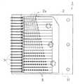
以下に、本発明に係る発音装置の第2具体例を図3及び図4に基づいて説明する。
【0051】
本例の発音装置は、各音階用に複数、設けたソレノイドが、同様に各音階用に複数、設けた星車を介して、発音体を打撃動作する構成とし、これらの星車によって、ソレノイドを設置する向きを変更可能にして、発音装置の薄型化を図ったものである。
【0052】
すなわち、図3及び図4に示すように、発音体2の各弁部2aに対応して、各弁部2aを弾いて発音動作させる専用の星車7を回転可能に設け、これらの星車7を回転駆動させるソレノイド5を、複数、設けるとともに、これらのソレノイド5を、その長手方向を発音体2の平面に平行にして、且つ、発音体2の近傍箇所に設置している。
【0053】
この星車7は、所定の同一形状に形成され、各弁部2a専用に、複数個、設けられるとともに、同一軸により、互いに独立に回転可能に軸支されている。
【0054】
すなわち、これらの星車7は、どのような回転位置でもソレノイド5と係合できるように、所定半径の外周に、8つの爪部が設けられており、これらの爪部の回転方向における前側は、鋭角なスロープ面に形成される一方、後側は、回転方向に直交する面に形成されている。
【0055】
従って、発音動作する際には、この星車7に設けた爪部の後側の直交面で、ソレノイド5の打撃体による突出動作を、確実に受けて、星車7自体の回転運動に変換するとともに、この回転動作に伴い、前側のスロープ面で、スムーズに発音体2の弁部2aと係合動作させ、この弁部2aを爪弾いて、発音動作できるようにしている。
【0056】
発音動作する際には、この星車によってソレノイドの突出動作を確実に受けて、これを星車自体の回転運動に変換するとともに、この回転動作に伴い、星車によってスムーズに発音体の弁部と係合動作がなされ、この弁部を爪弾いて、発音動作することができる。従って、星車を介することにより、ソレノイドの突出位置を星車の周囲に設けることができるので、ソレノイドと発音体との交差角度を適宜なものとすることができ、これにより配置の自由度が向上する。
【0057】
更に、これらの星車7を発音用に駆動するソレノイド5が、複数、設けられている。
【0058】
すなわち、これらのソレノイド5は、図4に示すように、その長手方向を、発音体2の平面に平行にして、発音体2の上方の近傍箇所、且つ、その突出打撃側の向きを、星車7の上側に対して、同一な所定距離を設けて対峙させて、図示を省略したケースに固定設置されている。
【0059】
また、これらのソレノイド5は、上記第1具体例と同様に、図示を省略した制御回路、又は、この制御回路に動作制御されたソレノイド駆動回路に、電気的に接続され、この制御回路によって、所定にソレノイド5の選択及び打撃動作を、プログラム制御している。
【0060】
以上説明したように、本具体例によれば、各音階用に複数、設けたソレノイドが、同様に各音階用に複数、設けた星車を介して、発音体を打撃動作する構成とし、これらソレノイドを選択し打撃動作させることをプログラム制御するとともに、これらの星車によって、ソレノイドを設置する長手方向の向きを、発音体の平面と同様な向きに設置したことにより、上記第1具体例と同様な効果を奏するのみならず、発音装置全体が占める高さ寸法を減少でき、薄型化を図ることができる。
【0061】
この結果、この発音装置を組込んで用いる装置の小型化を図ったり、発音装置を収納するスペースの制約を緩和でき、その設計の自由度を向上できるとともに、使用範囲を拡大することができる。
【0062】
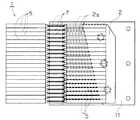
次に、本発明に係る発音装置の第3具体例を図5及び図6に基づいて説明する。
【0063】
本例の発音装置は、上述した第2具体例の発音装置の構成と基本的に同一であり、発音装置の上下寸法を増加させることなく、一つの星車7を、2系列のソレノイド5で発音駆動を可能にした点のみが異なり、これにより、曲目の調子等のように演奏動作の柔軟性を向上させて、演奏幅を広げると共に、テンポの速い曲目に対応可能にしたものである。
【0064】
この発音装置は、上記第2具体例の発音装置に、各星車7毎に、当該星車7を発音動作させる第2のソレノイド5を、追加して設けている。
【0065】
すなわち、これらの第2のソレノイド5は、図6に示すように、その長手方向を、発音体2の平面に平行にして、且つ、その突出打撃側の向きを、星車7の下側に対して、同一な所定距離を設けて対峙させて、図示を省略したケースに固定設置されている。
【0066】
また、これらのソレノイド5は、上記第2具体例と同様に、図示を省略した制御回路、又は、この制御回路に動作制御されたソレノイド駆動回路に、電気的に接続され、この制御回路によって、所定にソレノイド5の選択及び打撃動作を、プログラム制御している。
【0067】
以上説明したように、本具体例によれば、各音階用に複数、設けたソレノイドが、同様に各音階用に複数、設けた星車7を介して、発音体を打撃動作する構成とし、これらソレノイドを選択し打撃動作させることをプログラム制御するとともに、これらの星車7によって、2系列のソレノイドを設置する長手方向の向きを、発音体の平面と同様な向きに設置したことにより、発音装置全体が占める高さ寸法を増加せずに、上記第1具体例と同様な効果を奏するのみならず、曲目の調子等のように演奏動作の柔軟性を向上でき、演奏幅を広げるとともに、テンポの速い曲目に対応することができる。
【0068】
また、このような2系列のソレノイドを用いて、その発音動作を、和音演奏や、主旋律に伴奏を付けるというようなプログラム演奏をさせることが可能となり、演奏の表現力を向上することができる。
【0069】
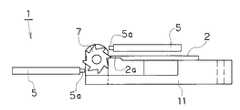
次に、本発明に係る発音装置の第4具体例を図7及び図8に基づいて説明する。
【0070】
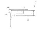
本例の発音装置は、ソレノイド5が、単一のソレノイドであるとともに、移動可能に設置されており、このソレノイドが移動して前記発音体の弁部を択一的に打撃するようにしたものであり、コストダウンや、多数のソレノイド5を必要なためコスト増加による発音体2の発音音階が制約されることを解消できるようにしたものである。
【0071】
すなわち、この発音装置は、単一のソレノイド5を用いて、このソレノイド5による打撃箇所を、任意に変更できるように構成され、発音動作させる発音体2の弁部2aを、適宜選択して、発音動作させることにより、異なる音階の発生音を得るようにしたものである。
【0072】
図7及び図8に示すように、この発音装置は、単一のソレノイド5のみを用いて、このソレノイド5が、ベルト駆動機構6により、その水平方向の位置を、任意の位置にスライド移動して選択できるように、ベルト駆動されている。
【0073】
このベルト駆動機構6は、平面視において、2つのベルトプーリ6a,6aによって掛け渡され、その掛け渡されたベルト長手面を、発音体2の発音側端部に沿って、対向させたタイミングベルト6bと、一方のベルトプーリ6aに回転駆動力を供給する図示を省略した電動モータ及び減速機構とから構成されている。
【0074】
すなわち、2つのベルトプーリ6a,6aが、発音体2の発音側で、且つその両脇の所定箇所に、図示を省略したケースに設置された垂直軸に軸支され、これらのベルトプーリ6a,6a間にタイミングベルト6bが掛け渡されている。
【0075】
また、これらのベルトプーリ6a,6aは、その外周に所定歯数の外歯が設けられるとともに、タイミングベルト6bの内周面には、ベルトプーリ6a,6aの外歯に係合する内歯が設けられており、互いに両者間に滑りを生じることなく係合させている。
【0076】
従って、一方のベルトプーリ6aを、所定に回転駆動することにより、タイミングベルト6bに取付けたソレノイド5の位置決めを確実に行うことができるとともに、その位置決め精度を十分に確保することができるようにしている。
【0077】
更に、タイミングベルト6bは、比較的に幅広に形成され、このタイミングベルト6bにソレノイド5を安定して、取付けられるようにしている。
【0078】
すなわち、このタイミングベルト6bの所定箇所に、ソレノイド5が、その打撃端部を垂直方向の上向きにして、取付けられ、このタイミングベルト6bが比較的に幅広ベルトなので、その向きを、常に、垂直方向の上向きに維持できるようにしている。
【0079】
また、ベルトプーリ6aつまりタイミングベルト6bを駆動するベルト駆動機構6の電動モータは、図示を省略した制御回路、又は、この制御回路に動作制御されたモータ駆動回路に、電気的に接続され、この制御回路により、そのモータによるベルト駆動の動作が、所定に制御されている。
【0080】
更に、上述した各具体例と同様に、この単一のソレノイド5も、この制御回路、又は、この制御回路に動作制御されたソレノイド駆動回路に、電気的に接続され、この制御回路により、ソレノイド5の発音用の打撃動作が、制御されている。
【0081】
従って、この制御回路によって、ベルト駆動によるソレノイド5の発音位置を選択する動作と、概位置に到達したソレノイド5の打撃動作とを、連係してプログラム制御できるように構成され、所定の順序で、所定の音階を、適切なタイミングで発音させて、所定の曲目を演奏できるようにしている。
【0082】
尚、後述する具体例において、ベルト駆動機構6を用いたものは、本例と同様に、制御回路に電気的に制御されており、本例と同様なソレノイド5と連係動作を行っているので、説明を省略することにする。
【0083】
以上説明したように、本具体例の発音装置によれば、発音体の発音部位に、その打撃側端部を対向させた単一のソレノイドを、ベルト駆動機構6によって、その打撃箇所の位置を変更可能に構成したことにより、上記第1具体例と同様な効果を奏するのみならず、低コスト化を図れるとともに、発音音階の制約を緩和することができる。
【0084】
すなわち、各音階を発音動作させる複数の専用ソレノイドを用いずに、単一のソレノイドを用いる構成であるため、必要なソレノイドの本数が削減され、コストの低廉化を図ることが可能となる。
【0085】
また、同様に各音階用に専用ソレノイドを複数、設けた構成によれば、音階数が増加すれば、それに応じた専用ソレノイドの必要本数が増加して、コスト的な負担が増大するので、コスト実用的な音階数の制限が生じるが、本具体例によれば、ベルト駆動を用いて、単一のソレノイドの発音部位を移動させて選択し、発音動作させるようにしているので、このような制約を解消することができ、コスト的な制約を受けることなく、必要な音階数を自由に得ることができる。
【0086】
次に、本発明に係る発音装置の第5具体例を図9及び図10に基づいて説明する。
【0087】
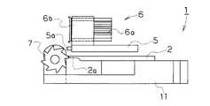
本例の発音装置は、上記第4具体例と同様に、単一のソレノイド5を、ベルト駆動機構6を用いて、その打撃箇所を、任意に変更できるように設けるとともに、上述した第2具体例と同様に、各音階用の弁部2a毎に複数の専用星車7を設け、この打撃箇所を変更するソレノイド5によって、星車7を択一的に選択し、この選択した星車7を介して、発音体2の弁部2aを打撃動作する構成とされ、演奏音階数の制約を解消するとともに、発音装置の薄型化や低コスト化を図ったものである。
【0088】
この発音装置は、上記第2具体例と同様に配置構成された複数の星車7と、同第2具体例の同様な向き及び位置に設置された単一のソレノイド5と、このソレノイド5を、その向きを維持したまま、発音体2の長手方向、つまり音階の高低方向にスライド移動するベルト駆動機構6とから構成されている。
【0089】
以上説明したように、本具体例の発音装置によれば、各音階用の弁部2a毎に複数の専用星車7を設けるとともに、任意の星車7を、単一のソレノイド5が、ベルト駆動機構6によって、選択可能に構成したことにより、上記第1具体例と同様な効果を奏するのみならず、低コスト化を図れるとともに、発音音階の制約を緩和することができる。
【0090】
次に、本発明に係る発音装置の第6具体例を図11及び図12に基づいて説明する。
【0091】
本例の発音装置は、基本的に、上述した第5具体例の発音装置に設けられたソレノイド5及びそのベルト駆動機構6を、2系列に、並列的に設けた構成とし、第3具体例と同様に、発音装置の上下寸法を増加させることなく、一つの星車7を、2つのソレノイド5で発音駆動を可能にした点のみが異なる。これにより、曲目の調子等のように演奏動作の柔軟性を向上させて、演奏幅を広げるとともに、テンポの速い曲目に対応可能にしたものである。
【0092】
以上説明したように、本具体例の発音装置によれば、各音階用の弁部毎に複数の専用星車7を設けるとともに、これらの星車7から任意の星車7を、ベルト駆動機構6によって、択一的に選択するソレノイド5を、少なくとも2系列設けたことにより、上記第5具体例と同様な効果を奏するのみならず、この2系列のソレノイド5による発音動作を連係させて、曲目の調子等のように演奏動作の柔軟性を向上させて、演奏幅を広げるとともに、テンポの速い曲目に対応することができ、演奏表現力を高めることができる。
【0093】
次に、本発明に係る発音装置の第7具体例を図13及び図14に基づいて説明する。
【0094】
本例の発音装置は、固定的に配置された複数のソレノイド5を2系列、並列的に設けることによって、この2系列のソレノイド5を協調動作させて、主旋律と伴奏の演奏を行う等ように、発音装置による演奏の表現力を高めたものである。
【0095】
この発音装置は、上述した第1具体例の発音装置に、同様にな配置構成の第2の系列のソレノイド5を設けて構成されている。
【0096】
以上説明したように、本具体例の発音装置によれば、各音階用の弁部毎に複数の専用ソレノイドを、少なくとも2系列設けたことにより、上記第6具体例と同様な効果を奏するのみならず、この2系列のソレノイドによる発音動作を連係させて、曲目の調子等のように演奏動作の柔軟性を向上させて、演奏幅を広げるとともに、テンポの速い曲目に対応することができ、演奏表現力を高めることができる。
【0097】
また、このような固定設置された2系列の複数ソレノイドを用いて、その発音動作を、和音演奏や、主旋律に伴奏を付けるというようなプログラム演奏をさせることが可能となり、演奏の表現力を向上することができる。
【0098】
次に、本発明に係る発音装置の第8具体例を図15及び図16に基づいて説明する。
【0099】
本例の発音装置は、ベルト駆動による可動ソレノイド5を2系列、並列的に設けることによって、発音装置による演奏の表現力を高めるとともに、必要なソレノイド本数を削減して、コストダウンを可能としたものである。
【0100】
この発音装置は、上述した第4具体例の発音装置に、用いられているベルト駆動による可動ソレノイド5を、新たに1つ追加した構成とされている。
【0101】
以上説明したように、本具体例の発音装置によれば、ベルト機構により、各音階用の弁部を選択して発音動作させるソレノイドを、少なくとも2系列設けたことにより、上記第7具体例と同様な効果を奏するのみならず、必要なソレノイド本数が削減され、コストダウンを図れるとともに、上記第7具体例と同様に、コスト的な制約を受けることなく、必要な音階数を自由に得ることができる。
【0102】
【発明の効果】
以上説明したように、本願第1請求項に記載した発明は、複数の弁部を有する発音体と、前記発音体の弁部を打撃するソレノイドとを備え、前記ソレノイドが移動可能に設置されており、このソレノイドが移動して前記発音体の複数の弁部を択一的に打撃するようにした発音装置である。
【0103】
従来のオルゴール等の発音装置は、演奏情報を機械的に記録した記録体を必要としていたが、本発明によれば、これらの記録体を不要にできるので、発音装置を設置するスペース効率を向上することが可能となるとともに、該記録体を用いるために必要な各種の設置条件を解除でき、発音装置による発音効果を優先させたり、他の装飾体等の設置を優先させたりした設置が可能となり、設置条件の自由度を向上することができる。
【0104】
更に、ソレノイドが移動可能に設置されており、このソレノイドが移動して前記発音体の複数の弁部を択一的に打撃するようにしているので、必要なソレノイドの本数が削減され、コストの低廉化を図ることが可能となる。
【0105】
本願第2請求項に記載した発明は、複数の弁部を有する発音体と、前記発音体の弁部を打撃するソレノイドとを備え、前記ソレノイドが、星車を介して、前記発音体の弁部を発音動作させるようにした発音装置である。
【0106】
発音動作する際には、この星車によってソレノイドの突出動作を確実に受けて、これを星車自体の回転運動に変換するとともに、この回転動作に伴い、星車によってスムーズに発音体の弁部と係合動作がなされ、この弁部を爪弾いて、発音動作することができる。従って、星車を介することにより、ソレノイドの突出位置を星車の周囲に設けることができるので、ソレノイドと発音体との交差角度を適宜なものとすることができ、これにより配置の自由度が向上する。
【0107】
本願第3請求項に記載した発明は、請求項1の発明において、前記ソレノイドが、星車を介して、前記発音体の弁部を発音動作させるようにした発音装置である。
【0108】
従って、前記第2請求項の発明と同様に、星車を介することにより、ソレノイドの突出位置を星車の周囲に設けることができるので、ソレノイドと発音体との交差角度を適宜なものとすることができ、これにより配置の自由度が向上する。
【0109】
本願第4請求項に記載した発明は、請求項1〜3の発明において、前記ソレノイドが単一である構成の発音装置である。
【0110】
とりわけソレノイドが単一である場合は、可及的にコストの低廉化を図ることが可能となる。
【図面の簡単な説明】
【図1】本発明の発音装置の第1具体例に係り、発音装置の主要な全体構成を示す平面図である。
【図2】本第1具体例の発音装置に係り、発音装置の主要な全体構成を示す側面図である。
【図3】本発明の発音装置の第2具体例に係り、発音装置の主要な全体構成を示す平面図である。
【図4】本第2具体例の発音装置に係り、発音装置の主要な全体構成を示す側面図である。
【図5】本発明の発音装置の第3具体例に係り、発音装置の主要な全体構成を示す平面図である。
【図6】本第3具体例の発音装置に係り、発音装置の主要な全体構成を示す側面図である。
【図7】本発明の発音装置の第4具体例に係り、発音装置の主要な全体構成を示す平面図である。
【図8】本第4具体例の発音装置に係り、発音装置の主要な全体構成を示す側面図である。
【図9】本発明の発音装置の第5具体例に係り、発音装置の主要な全体構成を示す平面図である。
【図10】本第5具体例の発音装置に係り、発音装置の主要な全体構成を示す側面図である。
【図11】本発明の発音装置の第6具体例に係り、発音装置の主要な全体構成を示す平面図である。
【図12】本第6具体例の発音装置に係り、発音装置の主要な全体構成を示す側面図である。
【図13】本発明の発音装置の第7具体例に係り、発音装置の主要な全体構成を示す平面図である。
【図14】本第7具体例の発音装置に係り、発音装置の主要な全体構成を示す側面図である。
【図15】本発明の発音装置の第8具体例に係り、発音装置の主要な全体構成を示す平面図である。
【図16】本第8具体例の発音装置に係り、発音装置の主要な全体構成を示す側面図である。
【符号の説明】
1 発音装置
2 発音体
2a 発音体の弁部
5 ソレノイド
5a ソレノイドの打撃体
6 ベルト駆動機構
6a ベルトプーリ
6b タイミングベルト
7 星車
11 発音体用の台座部[0001]
TECHNICAL FIELD OF THE INVENTION
The present invention relates to a sound generator suitable for a music box, a chime, a time signal mechanism of a timepiece, and the like.
[0002]
[Prior art]
In general, the sounding means used for notifying a clock or the like is not limited to a means for obtaining an artificial electronic sound using a sounding circuit and a speaker, etc. Also, there is known a music piece that plays a musical piece based on the pronunciation.
[0003]
That is, in the case of the electronic sound, the tone can be freely set, but only a pseudo tone can be obtained, and a live performance sound full of sense of quality and full of presence cannot be obtained.
[0004]
This type of sounding device is configured such that a metal sounding body that generates a predetermined musical scale and tone is installed, and the sounding portion of the sounding body is hit or played by various mechanisms, and the performance music is fixed. There are stationary cylinders and those recorded on interchangeable disks.
[0005]
In this cylinder type sounding device, a pin-shaped projection corresponding to a sounding portion of a sounding body and formed at a position of a sounding timing of a musical piece is formed on an outer periphery of a cylindrical cylinder having a predetermined diameter and length. In addition, this cylinder is configured to be rotatable and opposed to the sounding body, and when the cylinder is driven to rotate, each projection of the cylinder directly nails each sounding part of the sounding body, A predetermined song is played.
[0006]
The disc type is divided into a plurality of tracks on the surface of a disc formed in the shape of a thin disk having a predetermined diameter according to the sounding portion of the sounding body, and the tracks are divided according to the sounding timing of the musical scale assigned to the track. At a location in the direction, a projection or a hole-shaped playing engagement portion having a predetermined diameter is formed, and this disk is provided so as to face the sounding body, and is rotatably provided. Each of the engaging portions of the disc indirectly plucks each sounding portion of the sounding body via a star wheel to play a predetermined music piece.
[0007]
In this disk type, various types have been proposed in which the disk is replaceably provided and a plurality of songs on a plurality of disks can be played by hand or an automatic change mechanism.
[0008]
[Problems to be solved by the invention]
However, the above-mentioned conventional cylinder or disk-type sound generating device has the following problems in terms of the number of music pieces to be played, the playing time, the space for installing the sound generating device, and the like.
[0009]
That is, regarding the number of music pieces, in the cylinder type, a configuration is conceivable in which a plurality of music pieces are recorded in each extended block by extending the longitudinal direction, and the cylinder is slid to select one of the plurality of music pieces. However, it is disadvantageous in terms of physical installation space, reliability, and cost due to the complexity of the mechanism.
[0010]
As for the disk type, a plurality of songs can be selected by using a plurality of exchange disks as described above. However, in the case of manual operation, it takes time to exchange, and even in the case of automation, the cylinder type can be selected. Similar to the above, it is disadvantageous in terms of installation space, reliability, and cost.
[0011]
Further, with respect to the playing time, both the cylinder and the disc are basically the first song in one rotation operation, and increasing or decreasing the rotation speed in order to change the playing time requires changing the tone and timbre. Since it is not preferable, the performance time is always constant. In order to avoid these problems and extend the playing time, if the cylinder or disk is enlarged, the size of the device itself becomes large, which is disadvantageous in weight, space, cost, and small scale. It cannot be used for any purpose.
[0012]
In addition, in the cylinder or disk type, the information density on the outer periphery of the cylinder on which the mechanical performance information is recorded or the recording surface of the disk surface is low due to physical and practical constraints, making it difficult to reduce the size. There is a disadvantage that the use efficiency of the installation space is not very good. That is, since the engaging portion such as the protrusion provided on the outer surface of the recording medium is sounded as a mechanical drive source, the minimum gap distance between the engaging portions of the same scale is physically determined by itself. In addition, it is difficult to increase the information density on the recording surface in terms of manufacturing errors, high precision costs, and the like.
[0013]
In particular, in the case of a disk type, a minimum space is required to stably rotate a disk-shaped disk, and when a disk is replaceable, it is necessary to insert a disk from outside and set it. Since the installation space is limited to a place where the path space to reach is secured or the disk is easily exchanged, the tendency that the space utilization efficiency is reduced is further promoted.
[0014]
Therefore, the present invention eliminates the need for a recording medium that is a mechanical drive source for the sounding operation, eliminates the restrictions on the number of songs to be played and the playing time, and reduces the overall size of the device, thereby improving the space utilization efficiency. It is intended to provide a device.
[0015]
[Means for Solving the Problems]
The invention described in the first claim of the present application includes a sounding body having a plurality of valve portions, and a solenoid for striking the valve portion of the sounding body, wherein the solenoid is movably installed, and the solenoid moves. And a plurality of valve portions of the sounding body are selectively hit.
[0016]
Conventional sounding devices, such as music boxes, require recordings on which performance information is recorded mechanically. However, according to the present invention, these recordings can be dispensed with, thereby improving the space efficiency of installing sounding devices. It is also possible to cancel various installation conditions necessary for using the recording medium, and to prioritize the sound effect by the sound generator or to prioritize the installation of other decorative bodies and the like. Thus, the degree of freedom of the installation conditions can be improved.
[0017]
Further, the solenoid is installed so as to be movable, and the solenoid is moved so as to selectively hit a plurality of valve portions of the sounding body. Therefore, the number of required solenoids is reduced, and cost is reduced. It is possible to reduce the cost.
[0018]
The invention described in
[0019]
At the time of sounding operation, the star wheel reliably receives the projecting operation of the solenoid and converts it to the rotational movement of the star wheel itself. And an engagement operation is performed, and the sound can be generated by flicking the valve portion. Therefore, through the star wheel, the protruding position of the solenoid can be provided around the star wheel, so that the intersection angle between the solenoid and the sounding body can be made appropriate, thereby increasing the degree of freedom of arrangement. improves.
[0020]
According to a third aspect of the present invention, in the first aspect of the invention, there is provided a sound generating device according to the first aspect, wherein the solenoid causes a valve portion of the sounding body to sound through a star wheel.
[0021]
Therefore, similarly to the second aspect of the invention, the projecting position of the solenoid can be provided around the star wheel through the star wheel, so that the intersection angle between the solenoid and the sounding body is made appropriate. This increases the degree of freedom in arrangement.
[0022]
The invention described in claim 4 of the present application is the sound generating device according to any of
[0023]
In particular, when there is a single solenoid, the cost can be reduced as much as possible.
[0024]
BEST MODE FOR CARRYING OUT THE INVENTION
Hereinafter, a first specific example of the sound generating device according to the present invention will be described with reference to FIGS.
[0025]
It is to be noted that a description will be given of an example in which the sound generating device of the present embodiment is incorporated in a clock body (not shown). Operation shall be performed.
[0026]
As shown in FIGS. 1 and 2, the sounding
[0027]
As described above, by repeating the operation of selecting and hitting the
[0028]
In each of the specific examples described later, the configuration of the sounding
[0029]
The sounding
[0030]
A base end on one end side of the sounding
[0031]
The
[0032]
Further, these
[0033]
In addition, a plurality of
[0034]
That is, these
[0035]
The striking end of each of the
[0036]
Therefore, with the
[0037]
The
[0038]
The solenoid coil of the
[0039]
That is, at the time of the sounding operation by the
[0040]
In addition, at the time of the sounding operation by the impact of the
[0041]
The control circuit is configured by a microcomputer circuit having a general I / O port, a CPU, a memory, or the like, or a dedicated circuit, and sequentially selects and operates the above-described
[0042]
That is, the control circuit records the performance control data for the sequential operation of the
[0043]
Therefore, since the program control is used as described above, it is possible to eliminate restrictions on the number of music pieces to be played and the playing time when a mechanical performance data recording medium is used, thereby enabling various and flexible changes. At the same time, it is possible to increase the degree of freedom in compactness and arrangement.
[0044]
The volume of the sounding device can be adjusted by increasing or decreasing the speed of the projecting operation of the striking body by increasing or decreasing the drive current to the solenoid coil. In this manner, the sound volume is determined by the current value supplied to the solenoid coil. Can be adjusted, the adjustment work is easier than in the conventional type in which mechanical adjustment is performed, and the volume of each sound can be individually divided.
[0045]
In addition, in order to prevent the impacting body of the solenoid that strikes the sounding body from bouncing, for example, when hitting strongly for a large volume, in addition to the above-described felt cushioning material, a driving voltage is applied to the solenoid for sounding operation. A method of applying a predetermined reverse voltage pulse immediately after the application of the pulse, a method of appropriately adjusting the spring pressure for maintaining the impacting body in the initial posture, and the like can be given.
[0046]
As described above, according to this specific example, a sounding body having a sounding portion of a predetermined scale is provided with a plurality of solenoids provided exclusively for striking each sounding portion, and these solenoids are selected to perform a striking operation. By using a recording medium in which conventional performance information is recorded in a shape, the recording medium is used as a mechanical drive source, and the number of music pieces and performances that occur in a sounding device that performs sounding and performance operations. Dissatisfied points such as time and space for installing the sound generating device can be eliminated.
[0047]
That is, since the sounding body is made to perform a sounding operation without using a recording body in which performance information is recorded in a physical shape, an electrical program control is used. Can be changed freely and flexibly, and physical restrictions can be eliminated.
[0048]
In addition, since a recording body in which performance information is mechanically recorded is not required, space efficiency for installing a sound generating device can be improved, and various installations necessary for using the recording body can be achieved. The condition can be canceled, and the sound effect by the sounding device can be prioritized, or the installation of other decorations or the like can be prioritized. Therefore, the degree of freedom of the installation condition can be improved.
[0049]
Furthermore, since a plurality of solenoids are arranged and arranged, the structure is simple, sufficient reliability can be ensured, and downsizing can be achieved.
[0050]
Hereinafter, a second specific example of the sound generating device according to the present invention will be described with reference to FIGS.
[0051]
The sounding device of this example has a configuration in which a plurality of solenoids provided for each scale perform a striking operation of a sounding body via a plurality of provided star wheels for each scale in the same manner. The direction in which the sound is installed can be changed, thereby reducing the thickness of the sound generating device.
[0052]
That is, as shown in FIGS. 3 and 4, a
[0053]
A plurality of the
[0054]
That is, these
[0055]
Therefore, when the sounding operation is performed, the protruding operation of the
[0056]
At the time of sounding operation, the star wheel reliably receives the projecting operation of the solenoid and converts it to the rotational movement of the star wheel itself. And an engagement operation is performed, and the sound can be generated by flicking the valve portion. Therefore, through the star wheel, the protruding position of the solenoid can be provided around the star wheel, so that the intersection angle between the solenoid and the sounding body can be made appropriate, thereby increasing the degree of freedom of arrangement. improves.
[0057]
Further, a plurality of
[0058]
That is, as shown in FIG. 4, these
[0059]
These
[0060]
As described above, according to this specific example, a plurality of solenoids provided for each scale perform a striking operation of the sounding body through the plurality of star wheels similarly provided for each scale. In addition to program-controlling the selection and impact operation of the solenoid, the longitudinal direction in which the solenoid is installed by these star wheels is set in the same direction as the plane of the sounding body. In addition to providing the same effect, the height dimension occupied by the entire sound generating device can be reduced, and the thickness can be reduced.
[0061]
As a result, it is possible to reduce the size of the device that incorporates the sound generating device, reduce the restriction on the space for accommodating the sound generating device, improve the degree of freedom in design, and expand the range of use.
[0062]
Next, a third specific example of the sound generating device according to the present invention will be described with reference to FIGS.
[0063]
The sounding device of this example is basically the same as the structure of the sounding device of the second specific example described above, and one
[0064]
In this sound generating device, a
[0065]
That is, as shown in FIG. 6, these
[0066]
These
[0067]
As described above, according to this specific example, the plurality of solenoids provided for each scale perform a striking operation of the sounding body via the plurality of
[0068]
Further, by using such two-series solenoids, it is possible to perform a program performance such as a chord performance or an accompaniment to the main melody by using the two series of solenoids, thereby improving the expressive power of the performance.
[0069]
Next, a fourth specific example of the sound generating device according to the present invention will be described with reference to FIGS.
[0070]
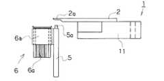
The sounding device of the present embodiment is such that the
[0071]
In other words, this sounding device is configured such that a
[0072]
As shown in FIGS. 7 and 8, this sounding device uses only a
[0073]
The
[0074]
That is, the two
[0075]
These belt pulleys 6a, 6a are provided with external teeth having a predetermined number of teeth on the outer periphery thereof, and have internal teeth engaging with the external teeth of the belt pulleys 6a, 6a on the inner peripheral surface of the
[0076]
Therefore, by rotating one
[0077]
Further, the
[0078]
That is, the
[0079]
The electric motor of the
[0080]
Further, similarly to each of the above-described specific examples, the
[0081]
Therefore, the control circuit is configured so that the operation of selecting the sounding position of the
[0082]
In a specific example to be described later, the one using the
[0083]
As described above, according to the sounding device of this specific example, the single solenoid whose striking end is opposed to the sounding portion of the sounding body is moved by the
[0084]
In other words, since a single solenoid is used instead of a plurality of dedicated solenoids that make each scale generate sound, the number of required solenoids can be reduced, and the cost can be reduced.
[0085]
Similarly, according to the configuration in which a plurality of dedicated solenoids are provided for each scale, if the number of scales is increased, the required number of dedicated solenoids is increased accordingly, and the cost burden is increased. Although a practical limit on the number of musical scales arises, according to this specific example, the sounding portion of a single solenoid is moved and selected using a belt drive, and the sounding operation is performed. The restriction can be eliminated, and the required number of scales can be obtained freely without being restricted by cost.
[0086]
Next, a fifth specific example of the sound generating device according to the present invention will be described with reference to FIGS.
[0087]
In the sound generating device of this embodiment, similarly to the fourth embodiment, a
[0088]
This sounding device includes a plurality of
[0089]
As described above, according to the sound generating device of this specific example, a plurality of
[0090]
Next, a sixth specific example of the sound generation device according to the present invention will be described with reference to FIGS.
[0091]
The sound generating device of the present example basically has a configuration in which the
[0092]
As described above, according to the sound generating device of this specific example, a plurality of
[0093]
Next, a seventh specific example of the sound generating device according to the present invention will be described with reference to FIGS.
[0094]
The sounding device of the present example is provided with a plurality of fixedly arranged
[0095]
This sounding device is configured by providing a second series of
[0096]
As described above, according to the sounding device of this example, the same effect as that of the sixth example can be obtained only by providing at least two systems of a plurality of dedicated solenoids for each scale valve unit. Rather, by linking the sound generation operations of these two series of solenoids, the flexibility of the performance operation, such as the tone of the music, can be improved, the performance width can be widened, and the music with a high tempo can be supported. Performance expressiveness can be enhanced.
[0097]
In addition, it is possible to use a plurality of fixedly-installed two-system multiple solenoids to make the sounding operation be a chord performance or a program performance such as accompaniment to the main melody, thereby improving the expressive power of the performance. can do.
[0098]
Next, an eighth example of the sound generating device according to the present invention will be described with reference to FIGS.
[0099]
In the sound generating device of this example, by providing two sets of
[0100]
This sound generating device has a configuration in which a belt-driven
[0101]
As described above, according to the sounding device of this specific example, at least two solenoids for selecting the valve portion for each musical scale and performing the sounding operation by the belt mechanism are provided, thereby achieving the seventh specific example. In addition to achieving the same effect, the required number of solenoids can be reduced, the cost can be reduced, and the required number of musical scales can be freely obtained without being restricted in cost as in the above-described seventh embodiment. Can be.
[0102]
【The invention's effect】
As described above, the invention described in
[0103]
Conventional sounding devices, such as music boxes, require recordings on which performance information is recorded mechanically. However, according to the present invention, these recordings can be dispensed with, thereby improving the space efficiency of installing sounding devices. It is also possible to cancel various installation conditions necessary for using the recording medium, and to prioritize the sound effect by the sound generator or to prioritize the installation of other decorative bodies and the like. Thus, the degree of freedom of the installation conditions can be improved.
[0104]
Further, the solenoid is installed so as to be movable, and the solenoid is moved so as to selectively hit a plurality of valve portions of the sounding body. Therefore, the number of required solenoids is reduced, and cost is reduced. It is possible to reduce the cost.
[0105]
The invention described in
[0106]
At the time of sounding operation, the star wheel reliably receives the projecting operation of the solenoid and converts it to the rotational movement of the star wheel itself. And an engagement operation is performed, and the sound can be generated by flicking the valve portion. Therefore, through the star wheel, the protruding position of the solenoid can be provided around the star wheel, so that the intersection angle between the solenoid and the sounding body can be made appropriate, thereby increasing the degree of freedom of arrangement. improves.
[0107]
According to a third aspect of the present invention, in the first aspect of the invention, there is provided a sound generating device according to the first aspect, wherein the solenoid causes a valve portion of the sounding body to sound through a star wheel.
[0108]
Therefore, similarly to the second aspect of the invention, the projecting position of the solenoid can be provided around the star wheel through the star wheel, so that the intersection angle between the solenoid and the sounding body is made appropriate. This increases the degree of freedom in arrangement.
[0109]
The invention described in claim 4 of the present application is the sound generating device according to any of
[0110]
In particular, when there is a single solenoid, the cost can be reduced as much as possible.
[Brief description of the drawings]
FIG. 1 is a plan view showing a main entire configuration of a sound generating device according to a first specific example of a sound generating device of the present invention.
FIG. 2 is a side view showing a main entire configuration of the sound generating device according to the sound generating device of the first specific example;
FIG. 3 is a plan view showing a main entire configuration of a sound generating device according to a second specific example of the sound generating device of the present invention.
FIG. 4 is a side view showing a main entire configuration of the sound generating device according to the sound generating device of the second specific example.
FIG. 5 is a plan view showing a main entire configuration of a sound generating device according to a third specific example of the sound generating device of the present invention.
FIG. 6 is a side view showing a main entire configuration of the sound generating device according to the sound generating device of the third specific example.
FIG. 7 is a plan view showing a main entire configuration of a sound generating device according to a fourth specific example of the sound generating device of the present invention.
FIG. 8 is a side view showing a main entire configuration of the sound generating device according to the sound generating device of the fourth specific example.
FIG. 9 is a plan view showing a main entire configuration of a sound generating device according to a fifth specific example of the sound generating device of the present invention.
FIG. 10 is a side view showing a main overall configuration of a sound generating device according to a sound generating device of a fifth specific example.
FIG. 11 is a plan view showing a main entire configuration of a sound generating device according to a sixth specific example of the sound generating device of the present invention.
FIG. 12 is a side view showing a main overall configuration of the sounding device according to the sounding device of the sixth specific example;
FIG. 13 is a plan view showing a main entire configuration of a sound generating device according to a seventh specific example of the sound generating device of the present invention.
FIG. 14 is a side view showing a main entire configuration of the sounding device according to the sounding device of the seventh specific example.
FIG. 15 is a plan view showing a main entire configuration of a sound generating device according to an eighth specific example of the sound generating device of the present invention.
FIG. 16 is a side view showing a main entire configuration of the sounding device according to the sounding device of the eighth specific example.
[Explanation of symbols]
1 sounding device
2 Pronunciation body
2a Valve of sounding body
5 Solenoid
5a Solenoid hitting body
6 Belt drive mechanism
6a Belt pulley
6b Timing belt
7 Star Car
11 Pedestal for sounding body
Claims (4)
Translated fromJapanesePriority Applications (1)
| Application Number | Priority Date | Filing Date | Title |
|---|---|---|---|
| JP01971598AJP3590519B2 (en) | 1998-01-30 | 1998-01-30 | Sounding device |
Applications Claiming Priority (1)
| Application Number | Priority Date | Filing Date | Title |
|---|---|---|---|
| JP01971598AJP3590519B2 (en) | 1998-01-30 | 1998-01-30 | Sounding device |
Publications (2)
| Publication Number | Publication Date |
|---|---|
| JPH11219171A JPH11219171A (en) | 1999-08-10 |
| JP3590519B2true JP3590519B2 (en) | 2004-11-17 |
Family
ID=12006999
Family Applications (1)
| Application Number | Title | Priority Date | Filing Date |
|---|---|---|---|
| JP01971598AExpired - Fee RelatedJP3590519B2 (en) | 1998-01-30 | 1998-01-30 | Sounding device |
Country Status (1)
| Country | Link |
|---|---|
| JP (1) | JP3590519B2 (en) |
Families Citing this family (2)
| Publication number | Priority date | Publication date | Assignee | Title |
|---|---|---|---|---|
| JP4995029B2 (en)* | 2007-10-18 | 2012-08-08 | 富士重工業株式会社 | Vehicle driving support device |
| KR101785870B1 (en)* | 2016-11-03 | 2017-10-13 | 한규락 | Orgel device |
- 1998
- 1998-01-30JPJP01971598Apatent/JP3590519B2/ennot_activeExpired - Fee Related
Also Published As
| Publication number | Publication date |
|---|---|
| JPH11219171A (en) | 1999-08-10 |
Similar Documents
| Publication | Publication Date | Title |
|---|---|---|
| JP6573355B2 (en) | Percussion instrument automatic performance device and automatic performance method | |
| JP3590519B2 (en) | Sounding device | |
| JP3358895B2 (en) | Sounding device | |
| US6960710B2 (en) | Electronic acoustic music engine | |
| US7321090B2 (en) | Automatic musical instrument | |
| JP3590518B2 (en) | Sounding device | |
| JP3788321B2 (en) | Electric music box | |
| JP3997956B2 (en) | Performance equipment | |
| JPH11272267A (en) | Music box | |
| JP3891410B2 (en) | Performance equipment | |
| JP3925261B2 (en) | Performance equipment | |
| KR102317824B1 (en) | Orgel | |
| JPH11272268A (en) | Music box | |
| CN207489457U (en) | A kind of tone color can music music box | |
| JP2913915B2 (en) | Handbell automatic performance device | |
| JP2009061001A (en) | Slot machine | |
| KR20240175619A (en) | Music Box Device | |
| JP3621242B2 (en) | Sound generator and clock device using the same | |
| JP3761424B2 (en) | Batting device | |
| JP3060567B2 (en) | Handbell automatic performance device | |
| JPH04372995A (en) | Automatic performance device for celesta | |
| JPH066868Y2 (en) | Hammering sound with function | |
| JP2002156968A (en) | Percussive music box | |
| JP2001175252A (en) | Sound producing device | |
| JP2581378B2 (en) | Handbell automatic performance device |
Legal Events
| Date | Code | Title | Description |
|---|---|---|---|
| A977 | Report on retrieval | Free format text:JAPANESE INTERMEDIATE CODE: A971007 Effective date:20040804 | |
| TRDD | Decision of grant or rejection written | ||
| A01 | Written decision to grant a patent or to grant a registration (utility model) | Free format text:JAPANESE INTERMEDIATE CODE: A01 Effective date:20040817 | |
| A61 | First payment of annual fees (during grant procedure) | Free format text:JAPANESE INTERMEDIATE CODE: A61 Effective date:20040820 | |
| R150 | Certificate of patent or registration of utility model | Free format text:JAPANESE INTERMEDIATE CODE: R150 | |
| R250 | Receipt of annual fees | Free format text:JAPANESE INTERMEDIATE CODE: R250 | |
| LAPS | Cancellation because of no payment of annual fees |