JP3589182B2 - External force measuring device - Google Patents
External force measuring deviceDownload PDFInfo
- Publication number
- JP3589182B2 JP3589182B2JP2000402395AJP2000402395AJP3589182B2JP 3589182 B2JP3589182 B2JP 3589182B2JP 2000402395 AJP2000402395 AJP 2000402395AJP 2000402395 AJP2000402395 AJP 2000402395AJP 3589182 B2JP3589182 B2JP 3589182B2
- Authority
- JP
- Japan
- Prior art keywords
- mass
- axis direction
- support beam
- external force
- angular velocity
- Prior art date
- Legal status (The legal status is an assumption and is not a legal conclusion. Google has not performed a legal analysis and makes no representation as to the accuracy of the status listed.)
- Expired - Lifetime
Links
- 239000000758substrateSubstances0.000claimsabstractdescription119
- 238000006073displacement reactionMethods0.000claimsabstractdescription88
- 238000001514detection methodMethods0.000claimsdescription211
- 230000001133accelerationEffects0.000claimsdescription87
- 238000005452bendingMethods0.000claimsdescription17
- 239000003990capacitorSubstances0.000description49
- 230000005540biological transmissionEffects0.000description12
- NJPPVKZQTLUDBO-UHFFFAOYSA-NnovaluronChemical compoundC1=C(Cl)C(OC(F)(F)C(OC(F)(F)F)F)=CC=C1NC(=O)NC(=O)C1=C(F)C=CC=C1FNJPPVKZQTLUDBO-UHFFFAOYSA-N0.000description12
- 238000004364calculation methodMethods0.000description11
- 230000007423decreaseEffects0.000description10
- 230000000694effectsEffects0.000description5
- 238000012545processingMethods0.000description5
- 230000035945sensitivityEffects0.000description4
- 230000001360synchronised effectEffects0.000description4
- 238000007796conventional methodMethods0.000description3
- 238000012986modificationMethods0.000description2
- 230000004048modificationEffects0.000description2
- 230000001105regulatory effectEffects0.000description2
- 239000002210silicon-based materialSubstances0.000description2
- 230000003321amplificationEffects0.000description1
- 230000008602contractionEffects0.000description1
- 230000003247decreasing effectEffects0.000description1
- 238000010586diagramMethods0.000description1
- 238000005516engineering processMethods0.000description1
- 239000000284extractSubstances0.000description1
- 238000004519manufacturing processMethods0.000description1
- 238000005259measurementMethods0.000description1
- 238000003199nucleic acid amplification methodMethods0.000description1
- 239000007787solidSubstances0.000description1
- 230000000087stabilizing effectEffects0.000description1
Images


Classifications
- G—PHYSICS
- G01—MEASURING; TESTING
- G01C—MEASURING DISTANCES, LEVELS OR BEARINGS; SURVEYING; NAVIGATION; GYROSCOPIC INSTRUMENTS; PHOTOGRAMMETRY OR VIDEOGRAMMETRY
- G01C19/00—Gyroscopes; Turn-sensitive devices using vibrating masses; Turn-sensitive devices without moving masses; Measuring angular rate using gyroscopic effects
- G01C19/56—Turn-sensitive devices using vibrating masses, e.g. vibratory angular rate sensors based on Coriolis forces
- G01C19/5719—Turn-sensitive devices using vibrating masses, e.g. vibratory angular rate sensors based on Coriolis forces using planar vibrating masses driven in a translation vibration along an axis
- G—PHYSICS
- G01—MEASURING; TESTING
- G01P—MEASURING LINEAR OR ANGULAR SPEED, ACCELERATION, DECELERATION, OR SHOCK; INDICATING PRESENCE, ABSENCE, OR DIRECTION, OF MOVEMENT
- G01P15/00—Measuring acceleration; Measuring deceleration; Measuring shock, i.e. sudden change of acceleration
- G01P15/02—Measuring acceleration; Measuring deceleration; Measuring shock, i.e. sudden change of acceleration by making use of inertia forces using solid seismic masses
- G01P15/08—Measuring acceleration; Measuring deceleration; Measuring shock, i.e. sudden change of acceleration by making use of inertia forces using solid seismic masses with conversion into electric or magnetic values
- G01P15/097—Measuring acceleration; Measuring deceleration; Measuring shock, i.e. sudden change of acceleration by making use of inertia forces using solid seismic masses with conversion into electric or magnetic values by vibratory elements
- G—PHYSICS
- G01—MEASURING; TESTING
- G01P—MEASURING LINEAR OR ANGULAR SPEED, ACCELERATION, DECELERATION, OR SHOCK; INDICATING PRESENCE, ABSENCE, OR DIRECTION, OF MOVEMENT
- G01P15/00—Measuring acceleration; Measuring deceleration; Measuring shock, i.e. sudden change of acceleration
- G01P15/02—Measuring acceleration; Measuring deceleration; Measuring shock, i.e. sudden change of acceleration by making use of inertia forces using solid seismic masses
- G01P15/08—Measuring acceleration; Measuring deceleration; Measuring shock, i.e. sudden change of acceleration by making use of inertia forces using solid seismic masses with conversion into electric or magnetic values
- G01P15/125—Measuring acceleration; Measuring deceleration; Measuring shock, i.e. sudden change of acceleration by making use of inertia forces using solid seismic masses with conversion into electric or magnetic values by capacitive pick-up
Landscapes
- Physics & Mathematics (AREA)
- General Physics & Mathematics (AREA)
- Engineering & Computer Science (AREA)
- Radar, Positioning & Navigation (AREA)
- Remote Sensing (AREA)
- Gyroscopes (AREA)
Abstract
Description
Translated fromJapanese【0001】
【発明の属する技術分野】
本発明は、例えば角速度、加速度等の外力を検出するのに好適に用いられる外力計測装置に関する。
【0002】
【従来の技術】
一般に、外力計測装置としては、基板と、該基板により支持梁を介して互いに直交する2方向に変位可能に支持された質量部と、該質量部を前記2方向のうち基板と平行な振動方向に振動させる振動発生手段と、前記質量部が前記振動方向と直交する検出方向に変位するときの変位量を角速度として検出する角速度検出手段とから構成された角速度センサが知られている(例えば、特開平5−312576号公報等)。
【0003】
この種の従来技術による角速度センサは、基板に対して平行なX軸、Y軸と垂直なZ軸のうち、例えばX軸方向に沿って質量部を所定の振幅で振動させ、この状態でZ軸周りの角速度が加わると、質量部にはY軸方向のコリオリ力が作用する。これにより、質量部はY軸方向に変位するので、角速度検出手段は、このときの質量部の変位量を静電容量等の変化として検出することにより、角速度に応じた検出信号を出力するものである。
【0004】
この場合、質量部は、基板に設けられた支持梁によってX軸方向等に変位(振動)可能に支持されている。そして、この支持梁は、基端側が基板に固定され、先端側が質量部に連結されると共に、角速度センサの作動時には、支持梁が撓み変形することによって質量部がX軸方向に振動する構成となっている。
【0005】
また、例えば特開平7−218268号公報に記載された他の従来技術では、音叉型センサと呼ばれる角速度センサを用い、基板上に配置した一対の質量部を互いに逆位相で振動させることにより、質量部から支持梁を介して基板に伝わる振動を一対の質量部によって互いに打消す構成としている。
【0006】
この場合、一対の質量部を支持する支持梁は、例えば各質量部を基板に対して1箇所で支持するために複数の折曲げ部が形成された複雑な形状を有し、先端側が分岐して各質量部にそれぞれ連結されている。
【0007】
【発明が解決しようとする課題】
ところで、上述した従来技術では、質量部が支持梁を介して基板に連結されているため、質量部が基板上で振動するときには、その振動が支持梁を介して基板側に伝わり易い。
【0008】
このため、角速度センサの作動時には、振動エネルギが基板側に漏れることによって質量部の振幅、振動速度等が減少し、角速度によるコリオリ力が小さくなって検出感度が不安定となる虞れがある。また、基板側に振動が伝わると、質量部は、角速度が加わっていないにも拘らず、基板の振動により検出方向に振動することがあるため、角速度の検出値に誤差が生じ易くなり、信頼性が低下するという問題がある。
【0009】
これに対し、他の従来技術では、一対の質量部を互いに逆位相で振動させることによって基板側に伝わる振動を打消す構成としている。しかし、これらの質量部は、複雑な折曲げ形状をもつ支持梁によって支持されているため、センサの製造時には、例えば支持梁の寸法、形状、撓み変形時の特性等を両側の質量部に対して均等に形成するのが難しい。
【0010】
このため、他の従来技術では、支持梁の寸法ばらつき、加工誤差等によって一対の質量部の振動状態に差が生じることがあり、各質量部から基板側に伝わる振動を安定的に打消すことができないという問題がある。
【0011】
一方、角速度センサの作動時には、衝撃等の外力によりセンサにY軸方向の加速度が加わると、質量部は、角速度によるコリオリ力だけでなく、加速度による慣性力によってもY軸方向に変位することがあり、このときの角速度成分と加速度成分とを含んだ変位量は角速度として検出されることになる。
【0012】
この結果、従来技術では、例えば角速度センサに僅かな衝撃等が加わるだけでも、角速度の検出信号に対して衝撃等による加速度成分が誤差として含まれるようになり、角速度の検出精度が低下するため、信頼性を向上させるのが難しいという問題がある。
【0013】
特に、センサに加わる加速度が質量部の振動周波数に近い周波数成分をもっている場合には、例えば振動周波数に応じた一定の周期で検出信号を同期整流して積分することにより角速度成分を抽出する同期検波等の信号処理を行ったとしても、加速度成分による誤差を確実に除去することはできない。
【0014】
本発明は上述した従来技術の問題に鑑みなされたもので、本発明の第1の目的は、質量部から支持梁を介して基板側に振動が伝わるのを防止でき、その振動状態を基板上で安定的に保持できると共に、検出感度、検出精度を高めて信頼性を向上できるようにした外力計測装置を提供することにある。
【0015】
また、本発明の第2の目的は、例えば角速度と加速度の両方が質量部に加わる場合でも、少なくとも角速度を加速度から分離して精度よく検出でき、その検出動作を安定化できるようにした外力計測装置を提供することにある。
【0016】
【課題を解決するための手段】
上述した課題を解決するために請求項1の発明は、基板と、該基板と隙間をもって対向し互いに直交するX軸,Y軸,Z軸からなる3軸方向のうちY軸方向に並んで配置され振動発生手段によってX軸方向に互いに逆位相で振動する3個以上の質量部と、Y軸方向に延び該各質量部をX軸方向に変位可能に連結する支持梁と、該支持梁と前記基板との間に設けられY軸方向に並んで配置された各質量部の間に位置する部位で該支持梁を前記基板に接続する固定部と、前記複数の質量部のうち少なくとも1個の質量部と前記支持梁との間に設けられ当該質量部をY軸方向に変位可能に支持する質量部支持梁と、前記各質量部に角速度または加速度が作用したときに該各質量部がY軸方向に変位する変位量を角速度または加速度として検出する外力検出手段とからなる構成を採用している。
【0017】
このように構成することにより、3個以上の質量部を支持梁によって振動方向(X軸方向)と直交するY軸方向に沿って連結でき、例えば3個以上の質量部のうち一部の質量部を振動発生手段によって振動させることにより、Y軸方向に延びた支持梁がX軸方向に撓み、互いに隣合う質量部をほぼ逆位相で振動させることができる。そして、この状態で質量部が角速度や加速度に応じてY軸方向に変位するときには、その変位量を外力検出手段によって検出することができる。また、3個以上の質量部を連結する支持梁の途中部位には、支持梁が各質量部と一緒に振動するときにほぼ一定の位置を保持する振動の節を配置することができる。
【0018】
また、3個以上の質量部のうち例えば逆位相で振動する2個の質量部は、角速度が加わるときにコリオリ力によって互いに逆方向に変位し、加速度が加わるときには慣性力によって互いに等しい方向に変位するから、これらの質量部の変位量を比較することにより、角速度と加速度を区別して検出することができる。
【0019】
また、請求項2の発明によると、固定部は支持梁のうち前記各質量部が支持梁のX軸方向の撓みにより互いに逆位相で振動するときの節に対応する部位を基板に接続する構成としている。
【0020】
これにより、固定部は、各質量部と支持梁とが該支持梁のX軸方向の撓みにより振動するときの振動の節に対応する位置で該支持梁を基板側に固定できるから、各質量部の振動が支持梁を介して基板側に伝わるのを抑制することができる。
【0021】
また、請求項3の発明によると、各質量部は、Y軸方向に対して中央に位置する第1の質量部と、Y軸方向に対して該第1の質量部の両側に位置する第2の質量部とによって構成し、前記第1の質量部はY軸方向に変位する質量部支持梁を介して前記支持梁に支持され、前記外力検出手段は前記第1の質量部がY軸方向に変位するときの変位量を検出する構成としている。
【0022】
これにより、第1の質量部を挟んで第2の質量部を対称に配置でき、これらの質量部をX軸方向に対して互いに逆位相で安定的に振動させることができる。そして、この状態で第1の質量部が角速度に応じてY軸方向に変位するときには、その変位量を外力検出手段により角速度として検出できる。また、センサに角速度が加わっていないときには、例えば支持梁がX軸方向に撓み変形することによって第1,第2の質量部がX軸方向だけに振動し、このとき質量部支持梁はY軸方向に変位しない状態を保持することができる。従って、第1の質量部が支持梁の撓み変形等によってY軸方向にも誤って変位するのを防止することができる。
【0023】
一方、請求項4の発明では、基板と、該基板と隙間をもって対向し互いに直交するX軸,Y軸,Z軸からなる3軸方向のうち振動発生手段によってX軸方向に振動する第1の質量部と、該第1の質量部を挟んでY軸方向の両側に設けられ振動発生手段によってX軸方向に振動する第2の質量部と、前記第1の質量部と第2の質量部との間に位置して第1の質量部を取囲む第3の質量部と、前記第2の質量部を互いにX軸方向に変位可能に連結する支持梁と、該支持梁に対して前記第3の質量部を連結する連結部と、前記第3の質量部に対して第1の質量部をY軸方向に変位可能に連結する質量部支持梁と、前記基板と支持梁との間に設けられ該支持梁を基板に接続する固定部と、前記第1の質量部に角速度が作用するときに該第1の質量部がY軸方向に変位する変位量を角速度として検出する外力検出手段とを備え、前記第1,第3の質量部と第2の質量部とは互いに逆位相で振動する構成としている。
【0024】
これにより、第1,第2,第3の質量部全体を振動発生手段によってX軸方向に振動させつつ、第1の質量部を角速度に応じてY軸方向に変位させることができる。また、センサに角速度が加わっていないときには、例えば支持梁がX軸方向に撓み変形することによって第1,第2,第3の質量部がX軸方向だけに振動し、このとき第1の質量部は、第3の質量部に取囲まれた位置でY軸方向に変位しない状態を保持できる。従って、第3の質量部は、支持梁の撓み変形等がY軸方向への変位となって第1の質量部に伝わるのを遮断することができる。
【0025】
また、請求項5の発明によると、固定部は支持梁のうち前記第1,第3の質量部と第2の質量部とが互いに逆位相で振動するときの節に対応する部位を前記基板に接続する構成としている。
【0026】
これにより、固定部は、第1,第2,第3の質量部と支持梁とが振動するときの振動の節に対応する位置で該支持梁を基板側に固定できるから、該各質量部の振動が支持梁を介して基板側に伝わるのを抑制することができる。
【0027】
また、請求項6の発明によると、各質量部は、Y軸方向に対して中央に位置する第1の質量部と、Y軸方向に対して該第1の質量部の両側に位置する第2の質量部とによって構成し、前記第1,第2の質量部はY軸方向に変位する第1,第2の質量部支持梁を介して前記支持梁にそれぞれ連結する構成としている。
【0028】
これにより、第1,第2の質量部は支持梁を介してX軸方向に振動でき、この状態で第1の質量部は第1の質量部支持梁により外力に応じてY軸方向に変位できると共に、第2の質量部は第2の質量部支持梁によってY軸方向に変位できる。そして、外力検出手段は、第1,第2の質量部の変位量を用いて角速度または加速度を検出することができる。
【0029】
一方、請求項7の発明では、基板と、該基板と隙間をもって対向し互いに直交するX軸,Y軸,Z軸からなる3軸方向のうち振動発生手段によってX軸方向に振動する第1の質量部と、該第1の質量部を挟んでY軸方向の両側に設けられ振動発生手段によってX軸方向に振動する第2の質量部と、前記第1の質量部と第2の質量部との間に位置して第1の質量部を取囲む第3の質量部と、前記第2の質量部を取囲む第4の質量部と、該第4の質量部を互いにX軸方向に変位可能に連結する支持梁と、該支持梁に対して前記第3の質量部を連結する連結部と、前記第3の質量部に対して第1の質量部をY軸方向に変位可能に連結する第1の質量部支持梁と、前記第4の質量部に対して第2の質量部をY軸方向に変位可能に連結する第2の質量部支持梁と、前記基板と支持梁との間に設けられ該支持梁を基板に接続する固定部と、前記第1,第2の質量部に角速度または加速度が作用するときに該第1,第2の質量部がY軸方向に変位する変位量を角速度または加速度として検出する外力検出手段とを備え、前記第1,第3の質量部と第2,第4の質量部とは互いに逆位相で振動する構成としている。
【0030】
これにより、第1,第2,第3,第4の質量部は支持梁を介してX軸方向に振動でき、この状態で第1,第2の質量部は、それぞれ第1,第2の質量部支持梁により外力に応じてY軸方向に変位することができる。また、第3の質量部は支持梁の撓み変形等が第1の質量部に伝わるのを遮断でき、第4の質量部は支持梁の撓み変形等が第2の質量部に伝わるのを遮断することができる。
【0031】
また、請求項8の発明によると、固定部は支持梁のうち前記第1,第3の質量部と第2,第4の質量部とが互いに逆位相で振動するときの節に対応する部位を前記基板に接続する構成としている。
【0032】
これにより、固定部は、第1,第2,第3,第4の質量部と支持梁とが振動するときの振動の節に対応する位置で該支持梁を基板側に固定できるから、該各質量部の振動が支持梁を介して基板側に伝わるのを抑制することができる。
【0033】
さらに、請求項9の発明によると、外力検出手段は、少なくとも前記各質量部に加わる角速度を加速度から分離して検出するため前記各質量部が互いに逆位相で振動しつつY軸方向に変位するときの変位量を合成して検出する構成としている。
【0034】
これにより、例えば逆位相で振動する2個の質量部は、角速度が加わるときにコリオリ力によって互いに逆方向に変位し、加速度が加わるときには慣性力によって互いに等しい方向に変位するから、例えば各質量部の変位量を減算することにより、これらの変位量のうち互いに同じ方向に変位した分(加速度成分)を相殺して除去することができ、少なくとも角速度を加速度から分離して検出することができる。
【0035】
また、請求項10の発明によると、外力検出手段は、前記第1の質量部と第2の質量部の間に位置して前記基板に設けられた固定側検出電極と、前記第1の質量部に設けられ該固定側検出電極とY軸方向の隙間を介して対向する第1の可動側検出電極と、前記第2の質量部に設けられ前記固定側検出電極とY軸方向の隙間を介して対向する第2の可動側検出電極とによって構成し、前記外力検出手段は固定側検出電極に対する第1,第2の可動側検出電極の変位量を静電容量の変化として並列に検出する構成としている。
【0036】
これにより、第1,第2の質量部が互いに逆位相で振動している状態で該各質量部に角速度が加わるときには、これらの質量部がコリオリ力により互いに逆方向に変位する。この結果、例えば第1,第2の可動側検出電極の両方を固定側検出電極に接近させることができ、固定側検出電極と可動側検出電極との間の静電容量を角速度の大きさに応じて増大させることができる。また、第1,第2の質量部に加速度が加わるときには、これらの質量部が互いに同方向に変位するから、第1,第2の可動側検出電極のうち一方の電極を固定側検出電極に接近させ、他方の電極を固定側検出電極から離間させることができ、加速度による各検出電極間の静電容量の変化を打消すことができる。
【0037】
また、請求項11の発明によると、外力検出手段は、互いに逆位相で振動する前記第1,第2の質量部のうち第1の質量部がY軸方向に変位するときの変位量を検出する第1の変位量検出部と、前記第2の質量部がY軸方向に変位するときの変位量を検出する第2の変位量検出部と、前記第1,第2の変位量検出部によりそれぞれ検出した変位量を用いて角速度と加速度とを個別に演算する外力演算部とによって構成している。
【0038】
これにより、第1,第2の変位量検出部は、互いに逆位相で振動する第1,第2の質量部がY軸方向に変位するときの変位量をそれぞれ検出することができる。そして、質量部に角速度と加速度の両方が加わる場合において、これら2つの検出値には、角速度に応じて互いに逆方向に変位した角速度成分と、加速度に応じて互いに等しい方向に変位した加速度成分とが含まれるから、外力演算部は、例えばこれら2つの検出値を加算および減算することにより角速度と加速度とを個別に演算することができる。
【0039】
さらに、請求項12の発明によると、外力検出手段は、前記基板側に固定して設けられ複数の電極部が櫛歯状に並んで形成された固定側検出電極と、前記質量部側に設けられ該固定側検出電極の各電極部とY軸方向の隙間を挟んで噛合する複数の電極部が形成された可動側検出電極とによって構成し、前記外力検出手段は前記固定側検出電極と可動側検出電極との間の静電容量の変化を前記質量部の変位量として検出する構成としている。
【0040】
これにより、固定側検出電極と可動側検出電極の各電極部を互いに噛合させ、これらの検出電極に大きな対向面積を与えることができる。そして、質量部が外力によりY軸方向に変位するときには、その変位量を各検出電極間の距離(静電容量)の変化として検出することができる。
【0041】
【発明の実施の形態】
以下、本発明の実施の形態による外力計測装置を、添付図面を参照しつつ詳細に説明する。
【0042】
ここで、図1および図2は本発明による第1の実施の形態を示し、本実施の形態では、外力計測装置として角速度センサを例に挙げて述べる。
【0043】
図中、21は本実施の形態による角速度センサ、22は該角速度センサ21の基板で、該基板22上には、例えば低抵抗なシリコン材料等を用いて後述の中央質量部23、外側質量部24、支持梁25、質量部支持梁26、固定部27、駆動電極29,30、検出電極33,34等が形成されている。
【0044】
23は基板22の中央近傍に配置された第1の質量部としての中央質量部で、該中央質量部23は、支持梁25と質量部支持梁26とを介して外側質量部24に連結され、これらの質量部23,24は、支持梁25によってX軸方向(振動方向)に変位可能に支持されている。また、中央質量部23は、質量部支持梁26によってY軸方向(検出方向)に変位可能に支持されている。
【0045】
24,24はY軸方向に対して中央質量部23の両側に配置された第2の質量部としての一対の外側質量部で、該各外側質量部24は、支持梁25の両端側に固着され、中央質量部23に対してX軸方向に変位可能となっている。また、これらの質量部23,24は、図1、図2に示す如く基板22と平行な平面内でY軸方向に沿ってほぼ直線状に配置されている。
【0046】
25,25は各外側質量部24をX軸方向に変位可能に連結する例えば2本の支持梁で、該各支持梁25は、互いにほぼ等しい長さ寸法をもって直線状に形成され、X軸方向に撓み変形可能となっている。また、支持梁25は、中央質量部23の左,右両側に配置され、Y軸方向に延びている。
【0047】
そして、角速度センサ21の作動時には、中央質量部23と外側質量部24とが支持梁25等を介して互いにほぼ逆位相でX軸方向に振動し、このとき支持梁25の長さ方向途中部位には、ほぼ一定の位置を保持する節部25A,25Aが配置される構成となっている。
【0048】
26,26はY軸方向に撓み変形可能に形成された例えば2本の質量部支持梁で、該各質量部支持梁26は、X軸方向に延びた直線状をなし、中央質量部23の左,右両側と各支持梁25の長さ方向中間部との間を連結している。また、質量部支持梁26は、中央質量部23を各支持梁25間でY軸方向に変位可能に支持し、中央質量部23が支持梁25の中間部位に対してX軸方向に変位するのを規制している。
【0049】
27,27,…は支持梁25の節部25Aを基板22に接続する例えば4個の固定部で、該各固定部27は、X軸方向に対して各支持梁25の左,右両側に2個ずつ配置され、Y軸方向に離間している。
【0050】
また、固定部27は、基板22上に固定された台座部27Aと、該台座部27Aから支持梁25に向けてX軸方向に突出し、基板22から離間して配置された腕部27Bとによって構成され、腕部27Bは、その先端側が支持梁25の節部25Aに連結されている。これにより、固定部27は、支持梁25と協働して質量部23,24をX軸方向に変位可能に支持している。そして、中央質量部23と外側質量部24とが逆位相で振動するときには、これらの質量部23,24の振動が支持梁25の節部25Aで互いに打消されるため、固定部27は、質量部23,24の振動が基板22に伝わるのを抑制するものである。
【0051】
一方、28,28は基板22上に設けられた駆動電極用支持部で、該各駆動電極用支持部28は、Y軸方向に対して外側質量部24の両側に配置されている。
【0052】
29,29は各駆動電極用支持部28に設けられた固定側駆動電極で、該各固定側駆動電極29は、支持部28から外側質量部24に向けて突出し、先端側がX軸方向にL字状をなして屈曲した複数の電極板29A,29A,…を有し、該各電極板29Aは、X軸方向に間隔をもって櫛歯状に配置されている。
【0053】
30,30は各固定側駆動電極29に対応して各外側質量部24に設けられた可動側駆動電極で、該各可動側駆動電極30は、外側質量部24から櫛歯状に突出し、固定側駆動電極29の各電極板29Aに噛合した複数の電極板30A,30A,…を有している。
【0054】
31,31は基板22と外側質量部24との間に設けられた振動発生手段としての振動発生部で、該各振動発生部31は、固定側駆動電極29と可動側駆動電極30とによって構成されている。そして、振動発生部31は、これらの駆動電極29,30間に交流の駆動信号を直流バイアス電圧と共に印加することによって、電極板29A,30A間に静電引力を交互に発生し、質量部23,24を図1中の矢示a1,a2方向に振動させるものである。
【0055】
32,32は基板22上に設けられた検出電極用支持部で、該各検出電極用支持部32は、Y軸方向に対して中央質量部23の両側に配置されている。
【0056】
33,33は各検出電極用支持部32に設けられた固定側検出電極で、該各固定側検出電極33は、例えば略F字状に形成され、X軸方向に突出して櫛歯状に配置された複数の電極板33A,33A,…を有している。
【0057】
34,34は各固定側検出電極33に対応して中央質量部23に設けられた可動側検出電極で、該各可動側検出電極34は、櫛歯状に配置された複数の電極板34A,34A,…を有し、該各電極板34Aは、固定側検出電極33の各電極板33AとY軸方向の隙間を介して噛合している。
【0058】
35は基板22と中央質量部23との間に設けられた外力検出手段としての角速度検出部で、該角速度検出部35は、固定側検出電極33と可動側検出電極34とからなる平行平板コンデンサを構成し、中央質量部23がZ軸周りの角速度に応じたコリオリ力によってY軸方向に変位するときには、この角速度を検出電極33,34間の静電容量の変化として検出するものである。
【0059】
本実施の形態による角速度センサ21は上述の如き構成を有するもので、センサの作動時には、まず各振動発生部31に交流の駆動信号を直流バイアス電圧と共に印加すると、各外側質量部24は、図1中の矢示a1,a2方向に振動する。このとき、各支持梁25がX軸方向に撓み変形し、外側質量部24の振動が支持梁25と質量部支持梁26を介して中央質量部23に伝わることにより、中央質量部23は、外側質量部24と逆位相で矢示a2,a1方向に振動する。
【0060】
そして、角速度センサ21にZ軸周りの角速度Ωが加わると、中央質量部23には、Y軸方向に対して下記数1の式に示すコリオリ力Fが作用する。このため、中央質量部23は、質量部支持梁26が撓むことにより、コリオリ力Fに応じてY軸方向に変位する。この結果、角速度検出部35の静電容量が変化するので、この静電容量の変化が角速度Ωとして検出される。
【0061】
【数1】
また、固定部27は、支持梁25の節部25Aを支持しているため、質量部23,24の振動が基板22に伝わるのを抑制することができる。
【0063】
かくして、本実施の形態によれば、中央質量部23と外側質量部24とを支持梁25によってX軸方向に変位可能に連結し、支持梁25の節部25Aを固定部27によって基板22に接続する構成としたので、質量部23,24が基板22上で振動するときには、隣合う中央質量部23と外側質量部24とを互いにほぼ逆位相で振動させることができる。そして、支持梁25の途中部位には、支持梁25が質量部23,24と一緒に振動するときにほぼ一定の位置を保持する節部25Aを配置でき、この節部25Aの位置では、質量部23,24の振動を互いに打消すことができる。
【0064】
この場合、中央質量部23と外側質量部24とをY軸方向に沿ってほぼ直線状に配置したので、例えば中央質量部23をX軸方向に振動させることによって、この振動を支持梁25によって外側質量部24に効率よく伝達でき、簡単な構造によって質量部23,24を逆位相で振動させることができる。また、中央質量部23を挟んで一対の外側質量部24を対称に配置することにより、質量部23,24全体として安定した振動状態を実現することができる。
【0065】
そして、固定部27は、支持梁25の節部25Aを介して中央質量部23と外側質量部24とを支持しているので、これらの振動が基板22に伝わるのを確実に抑制でき、振動発生部31から質量部23,24に加えられる振動エネルギを基板22側に逃がすことなく、質量部23,24を予め定められた振幅、振動速度等で効率よく振動させることができる。この結果、角速度Ωに応じて質量部23,24を所定の変位量分だけ確実に変位させることができ、センサの検出感度を安定させることができる。
【0066】
また、角速度が加わっていないときには、質量部23,24の振動が基板22に伝わることによって基板22が振動し、この振動で質量部23,24がY軸方向に振動するのを防止でき、センサの検出精度を高めて信頼性を向上させることができる。
【0067】
そして、特に本実施の形態では、中央質量部23を質量部支持梁26によって支持梁25に連結する構成としたので、角速度Ωが加わっていないときには、支持梁25が撓み変形することによって質量部23,24がX軸方向だけに振動し、質量部支持梁26はY軸方向に撓み変形しない状態を保持することができる。従って、支持梁25の撓み変形によって中央質量部23がX軸方向に振動しつつY軸方向にも変位するのを防止でき、検出精度を向上させることができる。
【0068】
また、可動側駆動電極30を外側質量部24に設けたので、可動側検出電極34が設けられた中央質量部23の構造を簡略化することができる。
【0069】
次に、図3および図4は本発明による第2の実施の形態を示し、本実施の形態の特徴は、第1,第2の質量部間に第3の質量部を設ける構成としたことにある。なお、本実施の形態では、第1の実施の形態と同一の構成要素に同一の符号を付し、その説明を省略するものとする。
【0070】
41は本実施の形態による角速度センサ、42は該角速度センサ41の基板で、該基板42上には、例えば低抵抗なシリコン材料等を用いて後述の中央質量部43、外側質量部44、枠状質量部45、支持梁46、連結部47、質量部支持梁48、固定部49、駆動電極51,52、検出電極55,56等が形成されている。
【0071】
43は基板42の中央近傍に配置された第1の質量部としての中央質量部で、該中央質量部43は、図3、図4に示す如く、略「日」の字をなす枠状体として形成され、互いに対向してX軸方向に延びた横枠部43A,43Aと、該各横枠部43Aの両端側を連結してY軸方向に延びた縦枠部43B,43Bと、各横枠部43A間に位置してX軸方向に延設され、各縦枠部43Bのほぼ中間部位を連結した中間枠部43Cとによって構成されている。
【0072】
そして、中央質量部43は、支持梁46、連結部47および質量部支持梁48を介して外側質量部44と枠状質量部45とに連結され、これらの質量部43,44,45は、支持梁46によってX軸方向(振動方向)に変位可能に支持されると共に、基板42と平行な平面内でY軸方向に沿ってほぼ直線状に並んで配置されている。また、中央質量部43は、質量部支持梁48によってY軸方向(検出方向)に変位可能に支持されている。
【0073】
44,44はY軸方向に対して中央質量部43の両側に配置された第2の質量部としての一対の外側質量部で、該各外側質量部44は、支持梁46の両端側に固着され、中央質量部43(枠状質量部45)に対してX軸方向に変位可能となっている。
【0074】
45は中央質量部43と各外側質量部44との間に配置された第3の質量部としての枠状質量部で、該枠状質量部45は、中央質量部43を取囲む四角形の枠状体によって形成され、互いに対向してX軸方向に延びた横枠部45A,45Aと、該各横枠部45Aの両端側を連結してY軸方向に延びた縦枠部45B,45Bとによって「口」字状に構成されている。そして、枠状質量部45は、その内側部位が質量部支持梁48を介して中央質量部43と連結され、外側部位が連結部47を介して支持梁46と連結されている。
【0075】
46,46は各外側質量部44をX軸方向に変位可能に連結する例えば2本の支持梁で、該各支持梁46は、互いにほぼ等しい長さ寸法をもって直線状に形成され、X軸方向に撓み変形可能となっている。また、支持梁46は、枠状質量部45の左,右両側に配置され、Y軸方向に延びている。
【0076】
そして、角速度センサ41の作動時には、中央質量部43(枠状質量部45)と外側質量部44とが支持梁46等を介して互いにほぼ逆位相でX軸方向に振動し、このとき支持梁46の長さ方向途中部位には、ほぼ一定の位置を保持する節部46A,46Aが配置される構成となっている。
【0077】
47,47は枠状質量部45と支持梁46とを連結する左,右の連結部で、該各連結部47は高い剛性をもって形成され、枠状質量部45が支持梁46に対してY軸方向に変位するのを規制している。
【0078】
48,48,…は中央質量部43と枠状質量部45とを連結する例えば4本の質量部支持梁で、該各質量部支持梁48は、一端側が中央質量部43の4隅に連結され、他端側がX軸方向に延びて枠状質量部45の各横枠部45Aに連結されると共に、Y軸方向に撓み変形可能となっている。そして、質量部支持梁48は、中央質量部43をY軸方向に変位可能に支持し、中央質量部43が枠状質量部45内でX軸方向に変位するのを規制している。
【0079】
49は支持梁46の節部46Aを基板42に接続する固定部で、該固定部49は、質量部43,44,45を取囲む四角形の枠状体によって形成され基板42上に固定された台座部49Aと、該台座部49Aの内側部位に一体に設けられ、基板42から離間して配置された例えば4個の腕部49B,49B,…とによって構成されている。
【0080】
そして、各腕部49Bは、X軸方向に対して各支持梁46の左,右両側に2個ずつ配置され、Y軸方向に離間している。また、腕部49Bは、第1の実施の形態とほぼ同様に、先端側が支持梁46の節部46Aに連結され、これにより固定部49は、質量部43,44,45の振動が基板42に伝わるのを抑制するものである。
【0081】
一方、50,50,…は基板42上に固定的に設けられた例えば4個の駆動電極用支持部で、該各駆動電極用支持部50は、Y軸方向に対し外側質量部44を挟んで両側に2個ずつ配置されている。
【0082】
51,51,…は各駆動電極用支持部50にそれぞれ設けられた固定側駆動電極で、該各固定側駆動電極51は、X軸方向に突出しY軸方向に間隔をもって櫛歯状に配置された複数の電極板51A,51A,…を有している。
【0083】
52,52,…は各固定側駆動電極51に対応して外側質量部44にそれぞれ設けられた可動側駆動電極で、該各可動側駆動電極52は、X軸方向に櫛歯状をなして突出し、固定側駆動電極51の各電極板51Aと噛合した複数の電極板52A,52A,…を有している。
【0084】
53,53,…は基板42と外側質量部44との間に設けられた振動発生手段としての振動発生部で、該各振動発生部53は、固定側駆動電極51と可動側駆動電極52とによって構成され、その電極板51A,52A間に静電引力を発生することにより、外側質量部44を図3中の矢示a1,a2方向に振動させるものである。
【0085】
54,54は中央質量部43の内側に位置して基板42上に設けられた2個の検出電極用支持部で、該各検出電極用支持部54は、Y軸方向に対して中央質量部43の中間枠部43Cを挟んで両側に配置されている。
【0086】
55,55,…は各検出電極用支持部54にそれぞれ複数個設けられた固定側検出電極で、該各固定側検出電極55は、X軸方向に突出しY軸方向の間隔をもって櫛歯状に配置された複数の電極板55A,55A,…を有している。
【0087】
56,56,…は各固定側検出電極55に対応して中央質量部43に複数個設けられた可動側検出電極で、該各可動側検出電極56は、X軸方向に櫛歯状をなして突出し、固定側検出電極55の各電極板55Aに対しY軸方向の隙間を挟んで噛合した複数の電極板56A,56A,…を有している。
【0088】
57,57は基板42と中央質量部43との間に設けられた外力検出手段としての角速度検出部で、該各角速度検出部57は、固定側検出電極55と可動側検出電極56とによって構成されている。そして、角速度検出部57は、中央質量部43がZ軸周りの角速度ΩによってY軸方向に変位するときに、電極板55A,56A間の静電容量が変化する平行平板コンデンサを形成している。
【0089】
本実施の形態による角速度センサ41は上述の如き構成を有するもので、次にその作動について説明する。
【0090】
まず、各振動発生部53に交流の駆動信号を直流バイアス電圧と共に印加すると、外側質量部44は、図4中の矢示a1,a2方向に振動する。このとき、各支持梁46がX軸方向に撓み変形し、外側質量部44の振動が連結部47を介して枠状質量部45に伝わることにより、枠状質量部45は、中央質量部43と一体となって外側質量部44に対し逆位相で矢示a2,a1方向に振動する。
【0091】
そして、角速度センサにZ軸周りの角速度Ωが加わると、中央質量部43は、質量部支持梁48が撓み変形することにより、枠状質量部45内でコリオリ力Fに応じてY軸方向に変位する。この結果、角速度検出部57の静電容量が変化するので、この静電容量の変化が角速度Ωとして検出される。
【0092】
また、固定部49の各腕部49Bは、支持梁46の節部46Aを支持しているため、質量部43,44,45の振動が基板42に伝わるのを抑制することができる。
【0093】
かくして、このように構成される本実施の形態でも、前記第1の実施の形態とほぼ同様の作用効果を得ることができる。そして、特に本実施の形態では、中央質量部43と外側質量部44との間に枠状質量部45を設ける構成としたので、角速度Ωが加わっていないときには、支持梁46が撓み変形しても、中央質量部43は、枠状質量部45内でX軸方向だけに振動することができる。
【0094】
従って、枠状質量部45は、支持梁46の撓み変形がY軸方向への変位となって中央質量部43に伝わるのを遮断でき、検出精度をより向上させることができる。
【0095】
次に、図5は本発明による第3の実施の形態を示し、本実施の形態の特徴は、固定部に二又状の腕部を設ける構成としたことにある。なお、本実施の形態では、前記第2の実施の形態と同一の構成要素に同一の符号を付し、その説明を省略するものとする。
【0096】
61は支持梁46の各節部46Aを基板42に接続する固定部で、該固定部61は、第2の実施の形態とほぼ同様に、基板42上に固定された枠状の台座部61Aと、該台座部61Aの内側部位に設けられた腕部61Bとによって構成されている。
【0097】
しかし、腕部61Bは、基端側が台座部61Aに1箇所で固定され先端側が略「T」字状に分岐した分岐部61B1と、該分岐部61B1の先端側からX軸方向に突出し、支持梁46の各節部46Aをそれぞれ支持する支持突部61B2,61B2とによって構成され、これらの分岐部61B1と支持突部61B2とは基板42から離間している。
【0098】
かくして、このように構成される本実施の形態でも、第2の実施の形態とほぼ同様の作用効果を得ることができる。そして、特に本実施の形態では、固定部61の腕部61Bが二又状に分岐する構成としたので、その分岐部61B1の基端側を台座部61A(基板42)に対して1箇所で固定することができる。
【0099】
従って、例えば基板42の熱膨張、熱収縮等によって支持梁46の各節部46A間で基板42の寸法Dが変化する場合でも、各節部46A間の間隔を拡大または縮小させる方向の応力が基板42側から腕部61Bや支持梁46等に加わるのを防止でき、信頼性を高めることができる。
【0100】
次に、図6ないし図9は本発明による第4の実施の形態を示し、本実施の形態の特徴は、角速度センサに角速度と加速度の両方が加わるときに、角速度を加速度から分離して検出する構成としたことにある。なお、本実施の形態では、前記第1の実施の形態と同一の構成要素に同一の符号を付し、その説明を省略するものとする。
【0101】
71は本実施の形態による角速度センサ、72は該角速度センサ71の基板で、該基板72上には、例えば低抵抗なシリコン材料等を用いて後述の中央質量部73、外側質量部74,75、支持梁76、質量部支持梁77,78、固定部79、駆動電極81,82、固定側検出電極85,86、可動側検出電極87,88,89,90等が形成されている。
【0102】
また、角速度センサ71は、これらの固定側検出電極85,86と可動側検出電極87,88,89,90とにより形成される後述のコンデンサC1,C2,C3,C4(図9参照)が互いにほぼ等しい電極形状をもつように構成されているものである。
【0103】
73は基板72の中央近傍に配置された第1の質量部としての中央質量部で、該中央質量部73は例えば四角形の平板状に形成されている。また、中央質量部73は支持梁76と質量部支持梁77,78とを介して外側質量部74,75と連結され、これらの質量部73,74,75は、図6、図7に示す如く基板72と平行な平面内でY軸方向に沿ってほぼ直線状に並んでいる。そして、中央質量部73は、後述の如く角速度、加速度等の外力が加わると、その大きさに応じたコリオリ力または慣性力を受けることにより質量部支持梁77を介してY軸方向に変位する構成となっている。
【0104】
74,75はY軸方向に対して中央質量部73の前,後両側に配置された第2の質量部としての一対の外側質量部で、該外側質量部74,75は例えば四角形の平板状に形成され、各支持梁76の両端側に質量部支持梁78を介してそれぞれ連結されている。そして、外側質量部74,75は、中央質量部73とほぼ同様に、角速度、加速度等の外力が加わることにより質量部支持梁78を介してY軸方向に変位するものである。
【0105】
ここで、質量部73,74,75の質量と支持梁77,78のばね定数とは予め適切に設定されており、後述の如く質量部73,74,75が角速度Ω、加速度αによって一緒に変位するときには、これらの変位量が互いにほぼ等しい大きさとなるように構成されている。
【0106】
76,76は中央質量部73を挟んで左,右両側に配置された例えば2本の支持梁で、該各支持梁76はX軸方向に撓み変形可能に形成され、互いにほぼ等しい寸法をもってY軸方向に延びている。そして、各支持梁76は、中央質量部73と外側質量部74,75とをX軸方向に変位可能に支持するものである。
【0107】
そして、角速度センサ71の作動時には、図8に示す如く、第1の実施の形態とほぼ同様に、隣合う中央質量部73と外側質量部74,75とが互いにほぼ逆位相でX軸方向に振動し、中央質量部73が振動によって矢示a1方向に変位するときには、外側質量部74,75が矢示a2方向に変位する。この場合、支持梁76の長さ方向途中部位には、振動時にほぼ一定の位置を保持する4箇所の節部76Aが配置されている。
【0108】
77,77はY軸方向に撓み変形可能に形成された第1の質量部支持梁で、該各第1の質量部支持梁77は中央質量部73の左,右両側と各支持梁76の長さ方向中間部位とを連結し、中央質量部73をY軸方向に変位可能に支持している。
【0109】
78,78,…はY軸方向に撓み変形可能に形成された第2の質量部支持梁で、該各第2の質量部支持梁78は、外側質量部74,75の左,右両側と各支持梁76の端部側とを連結し、これらの質量部74,75をY軸方向に変位可能に支持しているものである。
【0110】
79,79,…は各支持梁76の節部76Aを基板72に接続する例えば4個の固定部で、該各固定部79は、第1の実施の形態とほぼ同様に、台座部79Aと腕部79Bとによって構成されている。そして、各固定部79は各支持梁76を節部76Aの位置で支持することにより、質量部73,74,75の振動が基板72側に伝わるのを抑制するものである。
【0111】
一方、80,80は外側質量部74,75の前,後両側に位置して基板72上に設けられた駆動電極用支持部、81,81は該各駆動電極用支持部80に設けられた固定側駆動電極で、該各固定側駆動電極81は櫛歯状に並んだ複数の電極板81Aを有している。
【0112】
82,82は各固定側駆動電極81に対応して外側質量部74,75に設けられた可動側駆動電極で、該各可動側駆動電極82は固定側駆動電極81の各電極板81Aと噛合した複数の電極板82Aを有している。
【0113】
83,83は基板72と外側質量部74,75との間に設けられた振動発生手段としての振動発生部で、該各振動発生部83は固定側駆動電極81と可動側駆動電極82とによって構成され、外側質量部74,75を図6中の矢示a1,a2方向に振動させるものである。
【0114】
84,84は基板72上に設けられた例えば2個の検出電極用支持部で、該各検出電極用支持部84は中央質量部73の前,後両側に位置して外側質量部74,75との間に配置されている。
【0115】
85は各検出電極用支持部84のうち一方の支持部84から前,後方向に突設された固定側検出電極で、該固定側検出電極85は、中央質量部73側に配置された複数の電極板85Aと、外側質量部74側に配置された複数の電極板85Bとを有し、これらの電極板85A,85Bは櫛歯状に並んでいる。
【0116】
86は他方の検出電極用支持部84から前,後方向に突設された固定側検出電極で、該固定側検出電極86は、中央質量部73側に配置された複数の電極板86Aと、外側質量部75側に配置された複数の電極板86Bとを有している。
【0117】
87は中央質量部73から一方の固定側検出電極85に向けて突設された第1の可動側検出電極で、該可動側検出電極87は、固定側検出電極85の電極板85AとY軸方向の隙間を介して噛合する複数の電極板87Aを有し、後述の図9に示す如く、該固定側検出電極85との間で平行平板コンデンサC1を構成している。
【0118】
この場合、可動側検出電極87は、図6に示す如く、Y軸方向に対して電極板87Aの一側に位置する電極間隔d1が他側に位置する電極間隔d2よりも予め小さく形成されており(d1<d2)、コンデンサC1の静電容量に大きく影響する電極間隔d1は、中央質量部73がY軸方向に対してb1方向に変位したときに広がり、中央質量部73がb2方向に変位したときに狭くなるように構成されている。これにより、コンデンサC1の静電容量は、図9に示す如く中央質量部73がb1方向に変位したときに増大し、中央質量部73がb2方向に変位したときに減少するものである。
【0119】
88は中央質量部73から他方の固定側検出電極86に向けて突設された第1の可動側検出電極で、該可動側検出電極88は、可動側検出電極87とほぼ同様に、固定側検出電極86の各電極板86Aと噛合する複数の電極板88Aを有し、固定側検出電極86との間でコンデンサC2を構成している。
【0120】
そして、コンデンサC2の静電容量は、中央質量部73の変位方向に対してコンデンサC1と逆に増減するように予め設定されており、中央質量部73がb1方向に変位したときに静電容量が減少し、中央質量部73がb2方向に変位したときに静電容量が増大する構成となっている。
【0121】
89は外側質量部74,75のうち一方の質量部74に設けられた第2の可動側検出電極で、該可動側検出電極89は、固定側検出電極85の各電極板85BとY軸方向の隙間を挟んで噛合する複数の電極板89Aを有し、固定側検出電極85との間でコンデンサC3を構成している。
【0122】
この場合、可動側検出電極89は、固定側検出電極85(検出電極用支持部84)を挟んで可動側検出電極87とY軸方向の反対側に配置されている。そして、コンデンサC3の静電容量は、外側質量部74がb1方向に変位したときに減少し、外側質量部74がb2方向に変位したときに増大する構成となっている。
【0123】
90は他方の外側質量部75に設けられた第2の可動側検出電極で、該可動側検出電極90の各電極板90Aは、可動側検出電極89とほぼ同様に、固定側検出電極86の各電極板86Bとの間でコンデンサC4を構成している。そして、コンデンサC4の静電容量は、外側質量部75がb1方向に変位したときに増大し、外側質量部75がb2方向に変位したときに減少するものである。
【0124】
91は基板72と質量部73,74との間に設けられた外力検出手段としての角速度検出部で、該角速度検出部91は、固定側検出電極85,86のうち一方の固定側検出電極85と可動側検出電極87,89とによって構成され、コンデンサC1,C3が並列に接続されている。そして、角速度センサ71の作動時には、後述の如く質量部73,74がY軸方向に変位すると、角速度検出部91全体としての静電容量が変化するものである。
【0125】
92は基板72と質量部73,75との間に設けられた外力検出手段としての他の角速度検出部で、該角速度検出部92は、他方の固定側検出電極86と可動側検出電極88,90とによって構成され、コンデンサC2,C4が並列に接続されている。そして、角速度検出部92は、質量部73,75がY軸方向に変位することにより、その静電容量が変化する構成となっている。
【0126】
これにより、角速度センサ71は、角速度検出部91が質量部73,74の変位量をコンデンサC1,C3の容量変化として合成し、角速度検出部92が質量部73,75の変位量をコンデンサC2,C4の容量変化として合成することにより、後述の如く角速度Ωを加速度αから分離して検出するものである。
【0127】
本実施の形態による角速度センサ71は上述の如き構成を有するもので、次にその作動について説明する。
【0128】
まず、角速度センサ71の作動時には、図8に示す如く、各振動発生部83に交流の駆動信号を直流バイアス電圧と共に印加すると、第1の実施の形態とほぼ同様に、各支持梁76がX軸方向に撓み変形することにより、中央質量部73と外側質量部74,75とが互いに逆位相で矢示a1,a2方向に振動する。
【0129】
そして、角速度センサ71にZ軸周りの角速度Ωが加わると、例えば中央質量部73にはコリオリ力F1が矢示b1方向に付加される。また、外側質量部74,75は、中央質量部73と逆向きの速度方向をもって振動しているため、この速度方向に対応して逆向きのコリオリ力F2が矢示b2方向に付加される。
【0130】
この結果、例えば中央質量部73は質量部支持梁77を介して矢示b1方向に変位し、外側質量部74,75は質量部支持梁78を介して矢示b2方向に変位すると共に、これらの変位によって角速度検出部91,92の静電容量が変化する。また、この状態でY軸方向の加速度αが同時に加わると、質量部73,74,75には、この加速度αに応じた慣性力Faも付加されるようになる。
【0131】
そこで、図9を参照しつつ角速度検出部91,92の静電容量の変化について説明する。
【0132】
まず、質量部73,74,75に角速度Ωと加速度αとが加わると、角速度検出部91では、例えば質量部73,74がコリオリ力F1,F2により矢示b1,b2方向にそれぞれ変位する。これにより、コンデンサC1,C3の電極間隔は、いずれも初期状態と比較して狭くなるため、これらの静電容量はそれぞれ増大する。なお、ここではコリオリ力F1,F2の方が慣性力Faよりも大きい場合を例に挙げて述べる。
【0133】
この場合、コンデンサC1には、中央質量部73に加わるコリオリ力F1と慣性力Faの両方が静電容量を増大させる方向に作用する。従って、コンデンサC1の静電容量の変化量のうち、角速度Ωによる変化分を角速度成分ΔCw(ΔCw≧0)とし、慣性力Faによる変化分を加速度成分ΔCa(ΔCa≧0)とすれば、コンデンサC1の静電容量の変化量ΔC1は、下記数2の式のように角速度成分ΔCwと加速度成分ΔCaとを加えた大きさとなる。
【0134】
【数2】
また、コンデンサC3には、外側質量部74に加わるコリオリ力F2が静電容量を増大させる方向に作用し、慣性力Faがコリオリ力F2と逆向きに作用するから、コンデンサC3の静電容量の変化量ΔC3は、下記数3の式のように角速度成分ΔCwと加速度成分(−ΔCa)とを加算した値となる。
【0136】
【数3】
従って、角速度検出部91全体としての静電容量の変化量ΔCAを下記数4の式によって算出すると、コンデンサC1,C3の加速度成分ΔCaが互いに打消され、静電容量の変化量ΔCAは角速度成分ΔCwだけに対応した値となる。
【0138】
【数4】
一方、角速度検出部92について述べると、角速度検出部92では、例えば質量部73,75がコリオリ力F1,F2により矢示b1,b2方向にそれぞれ変位する。これにより、コンデンサC2,C4の電極間隔は、いずれも初期状態と比較して広がるため、これらの静電容量はそれぞれ減少する。
【0140】
この場合、コンデンサC2には、中央質量部73に加わるコリオリ力F1と慣性力Faの両方が電極間隔を広げて静電容量を減少させる方向に作用するから、その変化量ΔC2は、下記数5の式に示す如く、角速度成分(−ΔCw)と加速度成分(−ΔCa)とを加算した大きさとなる。
【0141】
【数5】
また、コンデンサC4には、外側質量部75に加わるコリオリ力F2が静電容量を減少させる方向に作用し、慣性力Faがコリオリ力F2と逆方向に作用するから、その変化量ΔC4は、下記数6の式のように角速度成分(−ΔCw)と加速度成分ΔCaとを加算した大きさとなる。
【0143】
【数6】
従って、角速度検出部92全体としての静電容量の変化量ΔCBを下記数7の式によって算出すると、コンデンサC2,C4の加速度成分ΔCaが互いに打消され、静電容量の変化量ΔCBは、角速度検出部91とほぼ同様に角速度成分ΔCwだけに対応した値となる。
【0145】
【数7】
そして、角速度センサ71の作動時には、角速度検出部91,92から静電容量の変化量ΔCA,ΔCBに応じた信号が出力され、これらの信号を用いて差動増幅等の信号処理を行うことにより、角速度Ωを精度よく検出することができる。
【0147】
また、コリオリ力F1,F2よりも慣性力Faの方が大きい場合には、外側質量部74,75が矢示b1方向に変位するようになるが、この場合にも加速度成分ΔCaは打消されるため、角速度Ωを検出することができる。さらに、角速度センサ71に矢示b2方向の加速度αが加わる場合にも同様に、角速度Ωを加速度αから分離して検出することができる。
【0148】
かくして、このように構成される本実施の形態でも、前記第1の実施の形態とほぼ同様の作用効果を得ることができる。そして、特に本実施の形態では、質量部73,74の変位量をコンデンサC1,C3の容量変化として合成した状態で検出する角速度検出部91と、質量部73,75の変位量をコンデンサC2,C4の容量変化として合成した状態で検出する角速度検出部92とを設ける構成としている。
【0149】
これにより、角速度検出部91,92は、角速度センサ71にZ軸周りの角速度Ωだけでなく、Y軸方向の加速度αが加わる場合でも、この加速度αによる静電容量の変化を打消して確実に除去でき、角速度Ωを加速度αから分離して安定的に検出できると共に、その検出精度をより高めることができる。
【0150】
この場合、角速度検出部91は、固定側検出電極85と可動側検出電極87,89とを対向させてコンデンサC1,C3を並列に接続し、これらの静電容量の変化を並列に検出すると共に、角速度検出部92は、固定側検出電極86と可動側検出電極88,90とを対向させてコンデンサC2,C4を並列に接続し、これらの静電容量の変化を並列に検出するようにしたので、角速度Ωと加速度αに応じた静電容量の変化量のうち加速度成分ΔCaをコンデンサC1,C3間およびコンデンサC2,C4間で確実に打消すことができ、複雑な演算処理等を行うことなく、簡単な電極構造で角速度成分ΔCwのみを検出することができる。
【0151】
次に、図10ないし図13は本発明による第5の実施の形態を示し、本実施の形態の特徴は、外力計測装置により角速度と加速度とを個別に検出する構成としたことにある。なお、本実施の形態では、前記第1の実施の形態と同一の構成要素に同一の符号を付し、その説明を省略するものとする。
【0152】
101は本実施の形態による外力センサ、102は該外力センサ101の基板で、該基板102上には、例えば低抵抗なシリコン材料等を用いて後述の中央質量部103、外側質量部104,105、枠状質量部106,107、支持梁108、質量部支持梁109,110、連結部111、固定部112、駆動電極114,115、固定側検出電極118,119,120,121、可動側検出電極122,123,124,125等が形成されている。
【0153】
103は基板102の中央近傍に配置された第1の質量部としての中央質量部で、該中央質量部103は、図10、図11に示す如く、前記第2の実施の形態とほぼ同様に、略「日」の字をなす枠状体として形成され、各横枠部103A、各縦枠部103Bおよび中間枠部103Cによって構成されている。
【0154】
そして、中央質量部103は、支持梁108、質量部支持梁109,110および連結部111を介して外側質量部104,105と枠状質量部106,107とに連結され、これらの質量部103,104,105,106,107は、支持梁108によってX軸方向に変位可能に支持されると共に、Y軸方向に沿ってほぼ直線状に並んでいる。また、中央質量部103は各質量部支持梁109によってY軸方向に変位可能に支持されている。
【0155】
104,105はY軸方向に対して中央質量部103の両側に配置された第2の質量部としての一対の外側質量部で、外側質量部104は、図11に示す如く各横枠部104Aと縦枠部104Bとを有する四角形の枠状体により形成され、外側質量部105も外側質量部104と同様の枠状体により形成されている。そして、外側質量部104,105は各質量部支持梁110によってY軸方向に変位可能に支持されている。
【0156】
106は中央質量部103と外側質量部104,105との間に配置された第3の質量部としての枠状質量部で、該枠状質量部106は、第2の実施の形態とほぼ同様に、中央質量部103を取囲む四角形の枠状体によって形成され、各横枠部106Aと縦枠部106Bとを有している。そして、枠状質量部106は、その外側部位が連結部111を介して支持梁108と連結され、その内側部位には質量部支持梁109を介して中央質量部103が連結されている。
【0157】
107,107は外側質量部104,105を取囲んで配置された第4の質量部としての枠状質量部で、該各枠状質量部107は各横枠部107Aと縦枠部107Bとを有する四角形の枠状体からなり、その外側部位が支持梁108に連結されると共に、その内側部位には質量部支持梁110を介して外側質量部104,105が連結されている。
【0158】
108,108は質量部103〜107をX軸方向に変位可能に支持する支持梁で、該各支持梁108は、枠状質量部106の左,右両側に配置され、Y軸方向に延びている。そして、外力センサ101の作動時には、質量部103,106と質量部104,105,107とが支持梁108等を介して互いにほぼ逆位相でX軸方向に振動し、このとき支持梁108の長さ方向途中部位には、ほぼ一定の位置を保持する4箇所の節部108Aが配置される構成となっている。
【0159】
109,109,…は中央質量部103と枠状質量部106とを連結する第1の質量部支持梁で、該各第1の質量部支持梁109は、第2の実施の形態とほぼ同様に、中央質量部103を4隅でY軸方向に変位可能に支持している。
【0160】
110,110,…は外側質量部104,105と各枠状質量部107とを連結する第2の質量部支持梁で、該各第2の質量部支持梁110は、外側質量部104,105をそれぞれ4隅でY軸方向に変位可能に支持している。
【0161】
111,111は枠状質量部106と支持梁108とを連結する左,右の連結部で、該各連結部111は高い剛性をもって形成され、枠状質量部106がY軸方向に変位するのを規制している。
【0162】
112は支持梁108を基板102に接続する固定部で、該固定部112は、第2の実施の形態とほぼ同様に、基板102上に固定された枠状の台座部112Aと、該台座部112Aから内側に突出して支持梁108の節部108Aに連結された例えば4個の腕部112Bとによって構成され、質量部103〜107の振動が基板102に伝わるのを抑制するものである。
【0163】
一方、113,113,…は外側質量部104,105の前,後両側に位置して基板102上に設けられた例えば4個の駆動電極用支持部、114,114,…は該各駆動電極用支持部113に設けられた固定側駆動電極で、該各固定側駆動電極114の各電極板114Aは、各枠状質量部107に設けられた可動側駆動電極115,115,…の各電極板115Aとそれぞれ噛合している。
【0164】
116,116,…は各駆動電極114,115によって構成された振動発生手段としての振動発生部で、該各振動発生部116は外側質量部104,105を図10中の矢示a1,a2方向に振動させるものである。
【0165】
117,117,…は質量部103,104,105の内側に位置して基板102上に設けられた例えば4個の検出電極用支持部で、該各検出電極用支持部117には、複数の電極板118A,119A,120A,121Aを有する固定側検出電極118,119,120,121がそれぞれ設けられている。
【0166】
122,123は中央質量部103の中間枠部103Cから前,後方向に突設された可動側検出電極、124,125は外側質量部104,105の内縁側に突設された可動側検出電極で、該可動側検出電極122,123,124,125の各電極板122A,123A,124A,125Aは、固定側検出電極118,119,120,121の各電極板118A,119A,120A,121Aとそれぞれ噛合している。
【0167】
126,127は後述の外力検出部130を構成する第1の変位量検出部で、該第1の変位量検出部126,127のうち一方の検出部126は、固定側検出電極118と可動側検出電極122とからなり、これらは中央質量部103が矢示b1方向に変位するときに静電容量が増大し、中央質量部103が矢示b2方向に変位するときに静電容量が減少するコンデンサC11を構成している。
【0168】
また、他方の変位量検出部127は検出電極119,123からなり、これらは中央質量部103が矢示b1方向に変位するときに静電容量が減少し、矢示b2方向に変位するときに静電容量が増大するコンデンサC12を構成している。
【0169】
128,129は外力検出部130を構成する第2の変位量検出部で、該第2の変位量検出部128,129のうち一方の検出部128は、固定側検出電極120と可動側検出電極124とからなり、これらは外側質量部104が矢示b1方向に変位するときに静電容量が減少し、外側質量部104が矢示b2方向に変位するときに静電容量が増大するコンデンサC13を構成している。
【0170】
また、他方の変位量検出部129は検出電極121,125からなり、これらは外側質量部105が矢示b1方向に変位するときに静電容量が増大し、矢示b2方向に変位するときに静電容量が減少するコンデンサC14を構成している。
【0171】
一方、図12において、130は外力センサ101に加わる角速度Ωと加速度αとを個別に検出する外力検出手段としての外力検出部で、該外力検出部130は、4個の変位量検出部126,127,128,129と、外力センサ101に接続された外力演算部としての加算アンプ131,132,133,134、差動アンプ135,136とを含んで構成されている。
【0172】
ここで、加算アンプ131は、変位量検出部127,129により検出されるコンデンサC12,C14の静電容量の変化量を加算して差動アンプ135に出力するものである。また、加算アンプ132は、変位量検出部126,128により検出されるコンデンサC11,C13の静電容量の変化量を加算して差動アンプ135に出力する。また、加算アンプ133は、変位量検出部127,128により検出されるコンデンサC12,C13の静電容量の変化量を加算して差動アンプ136に出力する。さらに、加算アンプ134は、変位量検出部126,129により検出されるコンデンサC11,C14の静電容量の変化量を加算して差動アンプ136に出力するものである。
【0173】
また、差動アンプ135は、後述の如く加算アンプ131,132による出力信号の差を角速度Ωに対応する検出信号として同期検波器137に出力し、同期検波器137は、例えば振動発生部116による振動周波数に対応した一定の周期で検出信号を同期整流して積分することにより、ノイズ等の除去を行うものである。また、差動アンプ136は、加算アンプ133,134による出力信号の差を加速度αに対応する検出信号として出力するものである。
【0174】
本実施の形態による外力センサ101は上述の如き構成を有するもので、次に図13を参照しつつ、その検出動作について説明する。
【0175】
まず、外力センサ101を作動させると、質量部103,106と質量部104,105,107とは、支持梁108を介して互いに逆位相で矢示a1,a2方向に振動する。
【0176】
そして、外力センサ101に角速度Ωと加速度αとが加わると、まず中央質量部103には、例えば角速度Ωによるコリオリ力F1が矢示b1方向に付加され、外側質量部104,105には、これと逆向きのコリオリ力F2が矢示b2方向に付加される。また、これらの質量部103,104,105には、例えば加速度αによる慣性力Faが矢示b1方向に加わるようになる。
【0177】
ここで、コリオリ力F1,F2の方が慣性力Faよりも大きい場合には、例えば中央質量部103は質量部支持梁109を介して矢示b1方向に変位し、外側質量部104,105は質量部支持梁110を介して矢示b2方向に変位すると共に、変位量検出部126,127,128,129の静電容量が変化する。
【0178】
この場合、変位量検出部126には、前記第4の実施の形態におけるコンデンサC1の場合とほぼ同様に、中央質量部103に加わるコリオリ力F1と慣性力Faの両方がコンデンサC11の静電容量を増大させる方向に作用する。従って、コンデンサC11の静電容量の変化量ΔC11は、前記数2の式と同様に、コリオリ力F1に対応する角速度成分ΔCwと慣性力Faに対応する加速度成分ΔCaとを用いて、下記数8の式のように表すことができる。
【0179】
【数8】
また、変位量検出部127には、コリオリ力F1と慣性力Faの両方がコンデンサC12の静電容量を減少させる方向に作用する。従って、コンデンサC12の静電容量の変化量ΔC12は下記数9の式のように表すことができる。
【0181】
【数9】
また、変位量検出部128には、コリオリ力F2がコンデンサC13の静電容量を増大させる方向に作用し、慣性力Faがコリオリ力F2と逆向きに作用するから、コンデンサC13の静電容量の変化量ΔC13は下記数10の式のようになる。
【0183】
【数10】
さらに、変位量検出部129には、コリオリ力F2がコンデンサC14の静電容量を減少させる方向に作用し、慣性力Faがこれと逆向きに作用するから、コンデンサC14の静電容量の変化量ΔC14は下記数11の式のようになる。
【0185】
【数11】
そして、加算アンプ131により静電容量の変化量ΔC12,ΔC14が加算され、加算アンプ132により静電容量の変化量ΔC11,ΔC13が加算されると、これらの加算結果の差に対応する検出信号S1が差動アンプ135から同期検波器137を介して出力される。この場合、検出信号S1は、前記数8〜11の式を用いて下記数12のように表すことができる。
【0187】
【数12】
また、加算アンプ133により静電容量の変化量ΔC12,ΔC13が加算され、加算アンプ134により静電容量の変化量ΔC11,ΔC14が加算されると、差動アンプ136は、これらの加算結果の差に対応する検出信号S2を出力する。この場合、検出信号S2は、下記数13のように表すことができる。
【0189】
【数13】
従って、角速度センサ101は、Z軸周りの角速度ΩとY軸方向の加速度αとが同時に加わる場合でも、これらの大きさを検出信号S1,S2として個別に検出することができる。また、コリオリ力F1,F2よりも慣性力Faの方が大きい場合や加速度αが矢示b2方向に加わる場合においても、角速度Ωと加速度αとを個別に検出することができる。
【0191】
かくして、このように構成される本実施の形態でも、前記第2,第4の実施の形態とほぼ同様の作用効果を得ることができる。そして、特に本実施の形態では、Y軸方向に対して中央質量部103の変位量を検出する変位量検出部126,127と、外側質量部104,105の変位量を検出する変位量検出部128,129と、外力演算部130とを設ける構成としている。
【0192】
これにより、外力演算部130は、第1の変位量検出部126,127により検出した中央質量部103の変位量と、第2の変位量検出部128,129により検出した外側質量部104、105の変位量とを加算アンプ131,132,133,134、差動アンプ135,136によって加算および減算でき、これらの変位量に含まれる角速度成分ΔCwと加速度成分ΔCaとを個別に演算することができる。
【0193】
従って、外力センサ101は、角速度Ω、加速度αに対応する検出信号S1,S2を正確に導出でき、単一の外力センサ101によりZ軸周りの角速度ΩとY軸方向の加速度αとをそれぞれ独立して安定的に検出できると共に、外力計測装置としての性能を向上させることができる。
【0194】
また、外側質量部104,105を取囲む2個の枠状質量部107を設けたので、該各枠状質量部107は、支持梁108の撓み変形がY軸方向への変位となって外側質量部104,105に伝わるのを確実に遮断でき、検出精度をより向上させることができる。
【0195】
なお、前記第2,第5の実施の形態では、固定部49,112の台座部49A,112Aから支持梁46,108の各節部46A,108Aに向けて直線状の腕部49B,112Bを突出させる構成としたが、本発明はこれに限らず、例えば図14に示す変形例のように、固定部49′の台座部49A′と腕部49B′との間に略コ字状の緩衝部49C′を設け、支持梁46の撓み変形によって腕部49B′に応力が加わるときには、この応力を緩衝部49C′が僅かに撓み変形することによって緩衝する構成としてもよい。また、第5の実施の形態においても、固定部112の台座部112Aと腕部112Bとの間に略コ字状の緩衝部を設ける構成としてもよい。
【0196】
また、前記第5の実施の形態では、外側質量部104,105を枠状質量部107によって取囲む構成としたが、本発明はこれに限らず、枠状質量部106,107のうち中央質量部103を取囲む枠状質量部106だけを設け,外側質量部104,105を取囲む枠状質量部107は省略し、外側質量部104,105を第4の実施の形態とほぼ同様の質量部支持梁によって支持梁108に連結する構成としてもよい。
【0197】
また、前記第5の実施の形態では、差動アンプ135から同期検波器137を介して角速度の検出信号S1を出力し、差動アンプ136から加速度αの検出信号S2を直接的に出力する構成としたが、本発明はこれに限らず、差動アンプ135,136の出力側には、例えば振動発生手段による振動周波数に近い高周波ノイズ等を検出信号S1,S2から除去するローパスフィルタ等を設ける構成としてもよい。
【0198】
【発明の効果】
以上詳述した通り、請求項1の発明によれば、基板上に配置した3個以上の質量部を支持梁によって連結し、Y軸方向に延びた支持梁を用いて該各質量部を互いに逆位相で振動させる構成としたので、例えば一部の質量部を振動させることにより、支持梁を介して各質量部を互いに逆位相で効率よく振動させることができる。そして、支持梁の長さ方向途中部位には、各質量部が振動するときに基板に対してほぼ一定の位置を保持する振動の節を配置でき、例えば支持梁の節の部位を基板側に固定することにより、各質量部の振動状態を安定させることができる。また、3個以上の質量部のうち例えば互いに逆位相で振動する2個の質量部の変位量を比較することにより、角速度を衝撃等による加速度から分離して検出でき、その検出動作を安定させることができる。
【0199】
また、請求項2の発明によれば、固定部は支持梁のうち各質量部が支持梁のX軸方向の撓みにより互いに逆位相で振動するときの節に対応する部位を基板に接続する構成としたので、固定部の位置では各質量部の振動を互いに打消すことができ、その振動が支持梁を介して基板に伝わるのを確実に抑制することができる。これにより、振動発生手段による振動エネルギを基板側に逃がすことなく、各質量部を所定の振幅、振動速度等で効率よく振動させることができ、外力(角速度)の検出感度を安定させることができる。また、基板に振動が伝わることによって各質量部が外力の検出方向に誤って変位するのを防止でき、外力の検出精度を高めて信頼性を向上させることができる。
【0200】
また、請求項3の発明によれば、各質量部を、質量部支持梁によって支持されY軸方向の変位量が角速度として検出される第1の質量部と、該第1の質量部の両側に位置する第2の質量部とによって構成したので、第1の質量部を挟んで第2の質量部を対称に配置でき、各質量部をX軸方向に対して互いに逆位相で安定的に振動させることができる。そして、この状態で第1の質量部が質量部支持梁を介してY軸方向に変位するときの変位量を角速度として検出することができる。また、角速度が加わっていないときには、例えば支持梁がX軸方向に撓み変形することによって第1,第2の質量部をX軸方向だけに振動させることができ、質量部支持梁はY軸方向に変位しない状態を保持することができる。従って、第1の質量部が支持梁の撓み変形等によってY軸方向にも誤って変位するのを防止でき、検出精度を高めて信頼性を向上させることができる。
【0201】
一方、請求項4の発明によれば、各第2の質量部を支持梁によって互いにX軸方向に変位可能に連結し、第3の質量部を連結部によって支持梁に連結し、第1の質量部を質量部支持梁によって第3の質量部内にY軸方向に変位可能に連結する構成としたので、第1,第2,第3の質量部全体を振動発生手段によってX軸方向に振動させつつ、第1の質量部が角速度により質量部支持梁を介してY軸方向に変位するときの変位量を角速度として検出でき、このとき各質量部の振動が支持梁を介して基板に伝わるのを確実に抑制することができる。また、第3の質量部は、角速度が加わっていないときに、支持梁の撓み変形等がY軸方向への変位となって第1の質量部に伝わるのを遮断でき、検出精度をより向上させることができる。
【0202】
また、請求項5の発明によれば、固定部は支持梁のうち各質量部が互いに逆位相で振動するときの節に対応する部位を基板に接続する構成としたので、各質量部の振動が支持梁を介して基板に伝わるのを確実に抑制することができる。
【0203】
また、請求項6の発明によれば、第1,第2の質量部をY軸方向に変位する第1,第2の質量部支持梁を介して支持梁にそれぞれ連結する構成としたので、第1,第2の質量部は支持梁を介して互い逆位相でX軸方向に振動しつつ、角速度または加速度の大きさに応じてY軸方向に変位することができる。従って、外力検出手段は、第1,第2の質量部の変位量を用いて角速度または加速度を検出することができる。
【0204】
さらに、請求項7の発明によれば、第1,第2の質量部は第1,第2の質量部支持梁を介して第3,第4の質量部に連結し、該第3,第4の質量部は支持梁に連結する構成としたので、第1,第2の質量部は支持梁を介して互い逆位相でX軸方向に振動しつつ、角速度または加速度の大きさに応じてY軸方向に変位することができる。また、第3,第4の質量部は支持梁の撓み変形等が第1,第2の質量部に伝わるのを遮断することができる。
【0205】
また、請求項8の発明によれば、固定部は支持梁のうち各質量部が互いに逆位相で振動するときの節に対応する部位を基板に接続する構成としたので、各質量部の振動が支持梁を介して基板に伝わるのを確実に抑制することができる。
【0206】
また、請求項9の発明によれば、外力検出手段は、各質量部が互いに逆位相で振動しつつ検出方向にそれぞれ変位するときの変位量を合成して検出する構成としたので、例えば各質量部に角速度と加速度とが加わるときには、各質量部の変位量を加算または減算等して合成することにより、これらの質量部の変位量のうち加速度により互いに同方向に変位した加速度成分を確実に打消すことができ、例えば角速度を加速度から分離して安定的に検出することができる。従って、外力計測装置に角速度だけでなく、衝撃等による加速度が加わる場合でも、角速度の検出精度を確実に向上させることができる。
【0207】
さらに、請求項10の発明によれば、外力検出手段は固定側検出電極に対する第1,第2の可動側検出電極の変位量を静電容量の変化として並列に検出する構成としたので、これらの可動側検出電極と固定側検出電極との間に2個のコンデンサを並列に形成することができる。そして、第1,第2の質量部に角速度と加速度とが加わるときには、第1,第2の可動側検出電極が固定側検出電極に対して互いに同方向に変位することにより、2個のコンデンサ間で静電容量の変化量のうち加速度成分を確実に打消すことができ、複雑な演算処理等を行うことなく、簡単な電極構造で角速度成分を検出することができる。
【0208】
これにより、第1,第2の質量部が互いに逆位相で振動している状態で該各質量部に角速度が加わるときには、これらの質量部がコリオリ力により互いに逆方向に変位する。この結果、例えば第1,第2の可動側検出電極の両方を固定側検出電極に接近させることができ、これらの間の静電容量を角速度の大きさに応じて増大させることができる。また、第1,第2の質量部に加速度が加わるときには、これらの質量部が互いに同方向に変位するから、第1,第2の可動側検出電極のうち一方の電極を固定側検出電極に接近させ、他方の電極を固定側検出電極から離間させることができ、加速度による各検出電極間の静電容量の変化を打消すことができる。
【0209】
また、請求項11の発明によれば、外力検出手段を、第1,第2の質量部の変位量をそれぞれ検出する第1,第2の変位量検出部と、該各変位量検出部の検出結果を用いて角速度と加速度とを個別に演算する外力演算部とにより構成したので、外力演算部は、例えば第1,第2の変位量検出部による各検出値の加算値および差を求めることにより、該各検出値に含まれる角速度成分と加速度成分とを個別に演算することができる。従って、各質量部に加わる角速度と加速度とをそれぞれ独立して安定的に検出でき、外力計測装置としての性能を向上させることができる。
【0210】
さらに、請求項12の発明によれば、外力検出手段を櫛歯状の固定側検出電極と可動側検出電極とによって構成したので、固定側検出電極と可動側検出電極の各電極部を互いに噛合させ、これらの検出電極に大きな対向面積を与えることができる。そして、質量部が外力によりY軸方向に変位するときには、その変位量を各検出電極間の距離(静電容量)の変化として検出することができる。
【図面の簡単な説明】
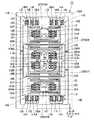
【図1】本発明の第1の実施の形態による角速度センサを示す平面図である。
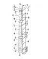
【図2】角速度センサを図1中の矢示II-II方向からみた断面図である。
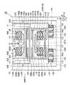
【図3】本発明の第2の実施の形態による角速度センサを示す平面図である。
【図4】中央質量部と枠状質量部とが外側質量部に対して逆位相で振動する状態を示す角速度センサの要部拡大図である。
【図5】本発明の第3の実施の形態による角速度センサを図4と同様位置からみた要部拡大図である。
【図6】本発明の第4の実施の形態による角速度センサを示す平面図である。
【図7】角速度センサを図6中の矢示VII-VII方向からみた断面図である。
【図8】中央質量部と外側質量部が角速度により互いに逆方向に変位する状態を示す平面図である。
【図9】角速度センサを模式的に示す図8の説明図である。
【図10】本発明の第5の実施の形態による外力センサを示す平面図である。
【図11】外力センサの一部を示す部分拡大図である。
【図12】外力センサに接続された外力演算部を示す構成図である。
【図13】外力センサの中央質量部と外側質量部が角速度により互いに逆方向に変位する状態を模式的に示す説明図である。
【図14】第2の実施の形態の変形例を示す角速度センサの要部拡大図である。
【符号の説明】
21,41,71 角速度センサ
22,42,72,102 基板
23,43,73,103 中央質量部(第1の質量部)
24,44,74,75,104,105 外側質量部(第2の質量部)
25,46,76,108 支持梁
25A,46A,76A,108A 節部
27,49,61,79,112 固定部
28,50,80,113 駆動電極用支持部
29,51,81,114 固定側駆動電極
29A,30A,33A,34A,51A,52A,55A,56A,81A,82A,85A,85B,86A,86B,87A,88A,89A,90A,114A,115A,118A,119A,120A,121A,122A,123A,124A,125A 電極板(電極部)
30,52,82,115 可動側駆動電極
31,53,83,116 振動発生部(振動発生手段)
33,55,85,86,118,119,120,121 固定側検出電極
34,56,87,88,89,90,122,123,124,125 可動側検出電極
35,57,91,92 角速度検出部(外力検出手段)
26,48,77,78,109,110 質量部支持梁
32,54,84,117 検出電極用支持部
45,106,107 枠状質量部(第3,第4の質量部)
47,111 連結部
101 外力センサ
126,127,128,129 変位量検出部
130 外力検出部(外力検出手段)
131,132,133,134 加算アンプ(外力演算部)
135,136 差動アンプ(外力演算部)[0001]
TECHNICAL FIELD OF THE INVENTION
The present invention relates to an external force measuring device suitably used for detecting an external force such as an angular velocity and an acceleration.
[0002]
[Prior art]
Generally, as an external force measuring device, a substrate, a mass portion supported by the substrate via a supporting beam so as to be displaceable in two directions orthogonal to each other, and a vibration direction parallel to the substrate in the two directions. 2. Description of the Related Art An angular velocity sensor is known that includes a vibration generating unit that vibrates in a vertical direction, and an angular velocity detecting unit that detects a displacement amount when the mass unit is displaced in a detection direction orthogonal to the vibration direction as an angular velocity (for example, JP-A-5-321576, etc.).
[0003]
Such an angular velocity sensor according to the related art is configured to vibrate a mass part with a predetermined amplitude along, for example, the X-axis direction among the X-axis parallel to the substrate and the Z-axis perpendicular to the Y-axis. When an angular velocity around the axis is applied, a Coriolis force in the Y-axis direction acts on the mass part. As a result, the mass section is displaced in the Y-axis direction, and the angular velocity detecting means outputs a detection signal corresponding to the angular velocity by detecting the displacement amount of the mass section at this time as a change in capacitance or the like. It is.
[0004]
In this case, the mass portion is supported by a support beam provided on the substrate so as to be displaceable (vibrated) in the X-axis direction or the like. The support beam has a configuration in which the base end side is fixed to the substrate, the tip end side is connected to the mass part, and the mass part vibrates in the X-axis direction by bending and deformation of the support beam when the angular velocity sensor is operated. Has become.
[0005]
Further, for example, in another conventional technique described in Japanese Patent Application Laid-Open No. 7-218268, an angular velocity sensor called a tuning fork type sensor is used, and a pair of mass parts arranged on a substrate are vibrated in opposite phases to each other to obtain a mass. Vibrations transmitted from the portions to the substrate via the support beams are canceled out by a pair of mass portions.
[0006]
In this case, the support beam supporting the pair of mass portions has a complicated shape in which a plurality of bent portions are formed, for example, to support each mass portion at one position with respect to the substrate, and the distal end side is branched. To each mass part.
[0007]
[Problems to be solved by the invention]
By the way, in the above-mentioned conventional technology, since the mass part is connected to the substrate via the support beam, when the mass part vibrates on the substrate, the vibration is easily transmitted to the substrate side via the support beam.
[0008]
For this reason, when the angular velocity sensor is operated, the vibration energy leaks to the substrate side, so that the amplitude, the vibration velocity, and the like of the mass section are reduced, and the Coriolis force due to the angular velocity is reduced, and the detection sensitivity may be unstable. In addition, when vibration is transmitted to the substrate side, the mass portion may vibrate in the detection direction due to vibration of the substrate even though the angular velocity is not applied. There is a problem that the property is reduced.
[0009]
On the other hand, in another conventional technique, a configuration is adopted in which a pair of mass parts are vibrated in opposite phases to cancel the vibration transmitted to the substrate side. However, since these mass parts are supported by support beams having a complicated bent shape, during the production of the sensor, for example, the dimensions, shape, characteristics at the time of bending deformation, etc. of the support beams are compared with the mass parts on both sides. It is difficult to form evenly.
[0010]
For this reason, in other conventional techniques, a difference may occur in the vibration state of the pair of mass parts due to dimensional variation of the support beam, processing error, and the like, and the vibration transmitted from each mass part to the substrate side may be stably canceled. There is a problem that can not be.
[0011]
On the other hand, when the angular velocity sensor is operated, if an acceleration in the Y-axis direction is applied to the sensor by an external force such as an impact, the mass unit may be displaced in the Y-axis direction by not only the Coriolis force due to the angular velocity but also the inertia force due to the acceleration. The displacement amount including the angular velocity component and the acceleration component at this time is detected as the angular velocity.
[0012]
As a result, in the related art, for example, even if a slight impact or the like is applied to the angular velocity sensor, an acceleration component due to the impact or the like is included as an error in the angular velocity detection signal, and the angular velocity detection accuracy is reduced. There is a problem that it is difficult to improve reliability.
[0013]
In particular, when the acceleration applied to the sensor has a frequency component close to the vibration frequency of the mass part, for example, synchronous detection that extracts the angular velocity component by synchronously rectifying and integrating the detection signal at a constant cycle corresponding to the vibration frequency. Even if such signal processing is performed, errors due to acceleration components cannot be reliably removed.
[0014]
SUMMARY OF THE INVENTION The present invention has been made in view of the above-described problems of the related art, and a first object of the present invention is to prevent vibration from being transmitted from a mass portion to a substrate side via a support beam, and to display the vibration state on the substrate. It is an object of the present invention to provide an external force measuring device capable of stably holding the external force and improving the detection sensitivity and the detection accuracy to improve the reliability.
[0015]
Further, a second object of the present invention is to provide an external force measurement device capable of accurately detecting at least the angular velocity separately from the acceleration and stabilizing the detection operation even when both the angular velocity and the acceleration are applied to the mass part. It is to provide a device.
[0016]
[Means for Solving the Problems]
In order to solve the above-described problem, the invention according to claim 1 is arranged in a Y-axis direction among three axes directions of a substrate and an X-axis, a Y-axis, and a Z-axis which are opposed to each other with a gap and are orthogonal to each other. And opposite phases in the X-axis direction by the vibration generating meansShakeMove3 or moreParts by mass ofExtends in the Y-axis directionA support beam for connecting the respective mass parts so as to be displaceable in the X-axis direction; and a support beam provided between the support beam and the substrate.In the part located between the mass parts arranged side by side in the Y-axis directionA fixing portion that connects the support beam to the substrate, and a mass that is provided between at least one of the plurality of mass portions and the support beam and supports the mass portion so as to be displaceable in the Y-axis direction. And an external force detecting means for detecting, as angular velocity or acceleration, an amount of displacement of each mass in the Y-axis direction when an angular velocity or acceleration acts on each mass. .
[0017]
With this configuration,3 or moreCan be connected by a support beam along a Y-axis direction orthogonal to the vibration direction (X-axis direction).3 or moreBy vibrating some of the mass parts by the vibration generating means,The support beam extending in the Y-axis direction bends in the X-axis direction,Adjacent mass parts can be vibrated in substantially opposite phases. Then, when the mass section is displaced in the Y-axis direction according to the angular velocity or the acceleration in this state, the amount of the displacement can be detected by the external force detecting means. Also,3 or moreA vibration node that maintains a substantially constant position when the support beam vibrates together with each of the mass portions can be arranged at an intermediate portion of the support beam connecting the mass portions.
[0018]
Also,Of three or more parts by massFor example, two mass parts vibrating in opposite phases are displaced in opposite directions by Coriolis force when an angular velocity is applied, and are displaced in the same direction by inertia force when an acceleration is applied. Are compared, angular velocity and acceleration can be distinguished and detected.
[0019]
Further, according to the invention of
[0020]
As a result, the fixed portion is configured such that each mass portion and the support beam areThe deflection of the support beam in the X-axis directionSince the support beam can be fixed to the substrate side at a position corresponding to a node of vibration when vibrating, it is possible to suppress the transmission of the vibration of each mass to the substrate side via the support beam.
[0021]
MaClaims3According to the invention, each of the mass parts includes a first mass part located at the center in the Y-axis direction, and a second mass part located on both sides of the first mass part in the Y-axis direction. Wherein the first mass section is supported by the support beam via a mass section support beam which is displaced in the Y-axis direction, and the external force detecting means is provided when the first mass section is displaced in the Y-axis direction. Is detected.
[0022]
Thereby, the second mass part can be arranged symmetrically with the first mass part interposed therebetween, and these mass parts can be stably vibrated in opposite phases with respect to the X-axis direction. When the first mass section is displaced in the Y-axis direction according to the angular velocity in this state, the amount of the displacement can be detected as the angular velocity by the external force detecting means. When no angular velocity is applied to the sensor, for example, the first and second mass portions vibrate only in the X-axis direction by, for example, bending and deformation of the support beam in the X-axis direction. It is possible to maintain a state in which it is not displaced in the direction. Therefore, it is possible to prevent the first mass portion from being erroneously displaced in the Y-axis direction due to bending deformation of the support beam or the like.
[0023]
Meanwhile, claims4In the invention of the above, a first mass portion vibrated in the X-axis direction by the vibration generating means among the three axial directions of the X axis, the Y axis, and the Z axis which are opposed to each other with a gap therebetween and are orthogonal to each other, A second mass portion provided on both sides in the Y-axis direction with the first mass portion interposed therebetween and vibrating in the X-axis direction by vibration generating means; and a position between the first mass portion and the second mass portion. A third mass portion surrounding the first mass portion, a support beam for connecting the second mass portion to each other so as to be displaceable in the X-axis direction, and a third mass portion with respect to the support beam. A connecting portion for connecting the first mass portion to the third mass portion so as to be displaceable in the Y-axis direction; and a supporting portion provided between the substrate and the supporting beam. A fixing portion connecting the beam to the substrate, and the first mass portion is displaced in the Y-axis direction when an angular velocity acts on the first mass portion. And a force detecting means for detecting an amount of displacement as angular velocity that, the first and third parts by theTwoThe mass part is configured to vibrate in opposite phases to each other.
[0024]
Thus, the first mass portion can be displaced in the Y-axis direction according to the angular velocity while the entire first, second, and third mass portions are vibrated in the X-axis direction by the vibration generating means. When no angular velocity is applied to the sensor, for example, the first, second, and third mass portions vibrate only in the X-axis direction due to, for example, bending of the support beam in the X-axis direction. The portion can maintain a state where it is not displaced in the Y-axis direction at a position surrounded by the third mass portion. Therefore, the third mass portion can prevent the bending deformation or the like of the support beam from being transmitted to the first mass portion as a displacement in the Y-axis direction.
[0025]
Claims5According to the invention, the fixing portion is configured to connect a portion corresponding to a node when the first and third mass portions and the second mass portion vibrate in opposite phases to each other in the support beam to the substrate. I have.
[0026]
Accordingly, the fixing portion can fix the support beam to the substrate at a position corresponding to a node of vibration when the first, second, and third mass portions and the support beam vibrate. Is transmitted to the substrate side via the support beam.
[0027]
Claims6According to the invention, each of the mass parts includes a first mass part located at the center in the Y-axis direction, and a second mass part located on both sides of the first mass part in the Y-axis direction. And the first and second mass sections are connected to the support beams via first and second mass section support beams that are displaced in the Y-axis direction.
[0028]
Thereby, the first and second mass portions can vibrate in the X-axis direction via the support beam, and in this state, the first mass portion is displaced in the Y-axis direction by the first mass portion support beam in response to an external force. At the same time, the second mass can be displaced in the Y-axis direction by the second mass support beam. Then, the external force detecting means can detect the angular velocity or the acceleration by using the displacement amounts of the first and second mass parts.
[0029]
Meanwhile, claims7In the invention of the above, a first mass portion vibrated in the X-axis direction by the vibration generating means among the three axial directions of the X axis, the Y axis, and the Z axis which are opposed to each other with a gap therebetween and are orthogonal to each other, A second mass portion provided on both sides in the Y-axis direction with the first mass portion interposed therebetween and vibrating in the X-axis direction by vibration generating means; and a position between the first mass portion and the second mass portion. A third mass surrounding the first mass, a fourth mass surrounding the second mass, and the fourth mass connected to each other so as to be displaceable in the X-axis direction. A supporting beam, a connecting portion connecting the third mass portion to the supporting beam, and a first connecting the first mass portion to the third mass portion so as to be displaceable in the Y-axis direction. A mass support beam, a second mass support beam connecting the second mass portion to the fourth mass portion so as to be displaceable in the Y-axis direction, A fixing portion provided between the plate and the support beam and connecting the support beam to the substrate, wherein the first and second mass portions are formed when an angular velocity or acceleration acts on the first and second mass portions; An external force detecting means for detecting a displacement amount displaced in the Y-axis direction as angular velocity or acceleration, wherein the first, third and second mass parts vibrate in opposite phases to each other. I have.
[0030]
Thereby, the first, second, third, and fourth mass parts can vibrate in the X-axis direction via the support beam, and in this state, the first and second mass parts respectively become the first and second mass parts. The mass support beam can be displaced in the Y-axis direction according to an external force. Further, the third mass portion can block the bending deformation of the support beam from being transmitted to the first mass portion, and the fourth mass portion can block the bending deformation of the support beam from being transmitted to the second mass portion. can do.
[0031]
Claims8According to the invention, the fixed portion connects to the substrate a portion corresponding to a node when the first, third mass portions and the second and fourth mass portions vibrate in opposite phases to each other in the support beam. Configuration.
[0032]
Accordingly, the fixing portion can fix the support beam to the substrate side at a position corresponding to a node of vibration when the first, second, third, and fourth mass portions and the support beam vibrate. The transmission of the vibration of each mass to the substrate via the support beam can be suppressed.
[0033]
Claims9According to the invention, the external force detection means detects at least the angular velocity applied to each of the mass parts separately from the acceleration to detect the amount of displacement when each of the mass parts is displaced in the Y-axis direction while vibrating in opposite phases to each other. It is configured to combine and detect.
[0034]
Thus, for example, two mass parts vibrating in opposite phases are displaced in opposite directions by Coriolis force when an angular velocity is applied, and displaced in the same direction by inertia force when an acceleration is applied. By subtracting the displacement amounts, the displacement amounts (acceleration components) of these displacement amounts that are displaced in the same direction can be canceled and removed, and at least the angular velocity can be detected separately from the acceleration.
[0035]
Claims10According to the invention, the external force detecting means is provided between the first mass part and the second mass part, the fixed side detection electrode provided on the substrate, and the external force detection means provided on the first mass part. A first movable-side detection electrode facing the fixed-side detection electrode via a gap in the Y-axis direction; and a first movable-side detection electrode provided on the second mass portion and facing the fixed-side detection electrode via a gap in the Y-axis direction. And two movable detection electrodes, and the external force detection means detects the displacement of the first and second movable detection electrodes with respect to the fixed detection electrode in parallel as a change in capacitance.
[0036]
Thus, when an angular velocity is applied to each of the mass parts in a state where the first and second mass parts are vibrating in opposite phases to each other, these mass parts are displaced in directions opposite to each other by Coriolis force. As a result, for example, both the first and second movable-side detection electrodes can be brought closer to the fixed-side detection electrode, and the capacitance between the fixed-side detection electrode and the movable-side detection electrode is reduced to the magnitude of the angular velocity. Can be increased accordingly. Further, when acceleration is applied to the first and second mass portions, these mass portions are displaced in the same direction, so that one of the first and second movable-side detection electrodes is used as the fixed-side detection electrode. The electrodes can be moved closer to each other and the other electrode can be separated from the fixed-side detection electrodes, thereby canceling the change in capacitance between the detection electrodes due to acceleration.
[0037]
Claims11According to the invention, the external force detecting means detects the amount of displacement when the first mass portion of the first and second mass portions vibrating in opposite phases to each other displaces in the Y-axis direction. An amount detection unit, a second displacement amount detection unit that detects a displacement amount when the second mass unit is displaced in the Y-axis direction, and displacements respectively detected by the first and second displacement amount detection units. An external force calculation unit that calculates the angular velocity and the acceleration individually using the quantities.
[0038]
Accordingly, the first and second displacement amount detection units can respectively detect the displacement amounts when the first and second mass units vibrating in opposite phases displace in the Y-axis direction. When both the angular velocity and the acceleration are applied to the mass part, these two detected values include an angular velocity component displaced in opposite directions according to the angular velocity, and an acceleration component displaced in the same direction according to the acceleration. Is included, the external force calculation unit can individually calculate the angular velocity and the acceleration by adding and subtracting these two detection values, for example.
[0039]
Claims12According to the invention, the external force detecting means comprises: a fixed-side detection electrode fixedly provided on the substrate side, a plurality of electrode portions formed in a comb-like shape; and a fixed-side detection electrode provided on the mass portion side. Each of the electrode portions of the electrode and a movable detection electrode formed with a plurality of electrode portions meshing with a gap in the Y-axis direction interposed therebetween, and the external force detection means is provided by the fixed-side detection electrode and the movable-side detection electrode. The change in the capacitance between the mass portions is detected as the amount of displacement of the mass portion.
[0040]
Thus, the electrode portions of the fixed-side detection electrode and the movable-side detection electrode can be engaged with each other, and a large facing area can be given to these detection electrodes. When the mass section is displaced in the Y-axis direction by an external force, the amount of displacement can be detected as a change in the distance (capacitance) between the detection electrodes.
[0041]
BEST MODE FOR CARRYING OUT THE INVENTION
Hereinafter, an external force measuring device according to an embodiment of the present invention will be described in detail with reference to the accompanying drawings.
[0042]
Here, FIG.andFigure2Shows a first embodiment according to the present invention, and in the present embodiment, an angular velocity sensor will be described as an example of an external force measuring device..
[0043]
In the figure,
[0044]
[0045]
[0046]
[0047]
Then, when the
[0048]
[0049]
, 27,... Are, for example, four fixing portions that connect the
[0050]
The fixing
[0051]
On the other hand,
[0052]
[0053]
[0054]
[0055]
[0056]
[0057]
[0058]
[0059]
The
[0060]
When an angular velocity Ω around the Z axis is applied to the
[0061]
(Equation 1)
Further, since the fixing
[0063]
Thus, according to the present embodiment, the
[0064]
In this case, since the
[0065]
Since the fixing
[0066]
When the angular velocity is not applied, the vibration of the
[0067]
SoParticularly, in the present embodiment, since the
[0068]
In addition, since the movable-
[0069]
Then figure3And figure4Is the first2This embodiment is characterized in that a third mass part is provided between the first and second mass parts. Note that, in the present embodiment, the same components as those in the first embodiment are denoted by the same reference numerals, and description thereof will be omitted.
[0070]
[0071]
[0072]
The
[0073]
[0074]
[0075]
[0076]
When the
[0077]
[0078]
, 48 are, for example, four mass support beams connecting the
[0079]
[0080]
Each of the
[0081]
On the other hand, 50, 50,... Are, for example, four drive electrode support portions fixedly provided on the
[0082]
[0083]
Are movable drive electrodes provided on the
[0084]
[0085]
[0086]
[0087]
Are movable side detection electrodes provided on the
[0088]
[0089]
The
[0090]
First, when an AC drive signal is applied to each
[0091]
Then, when an angular velocity Ω around the Z axis is applied to the angular velocity sensor, the
[0092]
Further, since each
[0093]
Thus, in the present embodiment configured as described above, substantially the same operation and effect as those in the first embodiment can be obtained. And especially in this Embodiment, since it was set as the structure which provided the frame-shaped
[0094]
Therefore, the frame-shaped
[0095]
Then figure5Is the first3This embodiment is characterized in that a bifurcated arm portion is provided on the fixing portion. Note that, in the present embodiment,2The same reference numerals are given to the same components as those of the embodiment, and the description thereof will be omitted.
[0096]
[0097]
However, the arm portion 61B has a branch portion 61B1 whose base end is fixed to the pedestal portion 61A at one place and whose distal end side branches in a substantially “T” shape, and protrudes in the X-axis direction from the distal end side of the branch portion 61B1 to support the arm 61B. It is composed of supporting projections 61B2 and 61B2 that support the
[0098]
Thus, also in the present embodiment configured as described above,2Almost the same effects as those of the embodiment can be obtained. In particular, in the present embodiment, the arm portion 61B of the fixing
[0099]
Therefore, even when the dimension D of the
[0100]
Then figure6Or figure9Is the first4The feature of this embodiment is that when both the angular velocity and the acceleration are applied to the angular velocity sensor, the angular velocity is separated from the acceleration and detected. Note that, in the present embodiment, the same components as those in the first embodiment are denoted by the same reference numerals, and description thereof will be omitted.
[0101]
[0102]
The
[0103]
[0104]
[0105]
Here, the masses of the
[0106]
[0107]
When the
[0108]
[0109]
.. Are second mass support beams 78 which are formed so as to be able to bend and deform in the Y-axis direction. Each of the second mass support beams 78 is provided on both the left and right sides of the outer
[0110]
Are fixed portions, for example, four connecting
[0111]
On the other hand,
[0112]
[0113]
83, 83 are vibration generating units as vibration generating means provided between the
[0114]
[0115]
[0116]
[0117]
[0118]
In this case, the movable
[0119]
[0120]
The capacitance of the capacitor C2 is set in advance so as to increase or decrease in the direction of displacement of the
[0121]
[0122]
In this case, the movable-
[0123]
[0124]
[0125]
[0126]
Accordingly, in the
[0127]
The
[0128]
First, when the
[0129]
When an angular velocity Ω around the Z-axis is applied to the
[0130]
As a result, for example, the
[0131]
So figure9The change in the capacitance of the
[0132]
First, when the angular velocity Ω and the acceleration α are applied to the
[0133]
In this case, both the Coriolis force F1 and the inertial force Fa acting on the
[0134]
(Equation 2)
Further, the Coriolis force F2 applied to the
[0136]
(Equation 3)
Therefore, when the amount of change ΔCA in the capacitance of the entire angular
[0138]
(Equation 4)
On the other hand, regarding the angular
[0140]
In this case, since both the Coriolis force F1 and the inertial force Fa applied to the
[0141]
(Equation 5)
Further, on the capacitor C4, the Coriolis force F2 applied to the
[0143]
(Equation 6)
Therefore, when the amount of change .DELTA.CB of the capacitance of the entire angular
[0145]
(Equation 7)
When the
[0147]
When the inertial force Fa is larger than the Coriolis forces F1 and F2, the outer
[0148]
Thus, also in the present embodiment configured as described above,OneIt is possible to obtain substantially the same operation and effect as the embodiment. In particular, in the present embodiment, the
[0149]
Accordingly, even when the
[0150]
In this case, the
[0151]
Then figure10Or figureThirteenIs the first5This embodiment is characterized in that the external force measuring device detects the angular velocity and the acceleration individually. Note that, in the present embodiment, the same components as those in the first embodiment are denoted by the same reference numerals, and description thereof will be omitted.
[0152]
[0153]
[0154]
The
[0155]
[0156]
[0157]
[0158]
[0159]
[0160]
.. Are second mass support beams connecting the outer
[0161]
Reference numerals 111 and 111 denote left and right connecting portions for connecting the frame-shaped
[0162]
[0163]
On the other hand, 113, 113,... Are provided on the
[0164]
,
[0165]
.. Are, for example, four detection electrode support portions provided on the
[0166]
[0167]
[0168]
Further, the other displacement
[0169]
[0170]
The other
[0171]
Meanwhile, the figure12In the figure, 130 is an external force detecting unit as external force detecting means for individually detecting the angular velocity Ω and the acceleration α applied to the
[0172]
Here, the
[0173]
Further, the
[0174]
The
[0175]
First, when the
[0176]
When the angular velocity Ω and the acceleration α are applied to the
[0177]
Here, when the Coriolis forces F1 and F2 are larger than the inertial force Fa, for example, the
[0178]
In this case, the displacement amount detection unit 1264In substantially the same manner as in the case of the capacitor C1 in the embodiment, both the Coriolis force F1 and the inertial force Fa applied to the
[0179]
(Equation 8)
Further, both the Coriolis force F1 and the inertial force Fa act on the displacement
[0181]
(Equation 9)
Further, the Coriolis force F2 acts on the
[0183]
(Equation 10)
Further, the Coriolis force F2 acts on the
[0185]
[Equation 11]
When the change amounts ΔC12 and ΔC14 of the capacitance are added by the
[0187]
(Equation 12)
When the change amounts ΔC12 and ΔC13 of the capacitance are added by the
[0189]
(Equation 13)
Therefore, even when the angular velocity Ω around the Z-axis and the acceleration α in the Y-axis direction are applied simultaneously, the
[0191]
Thus, also in the present embodiment configured as described above,2,FourIt is possible to obtain substantially the same operation and effect as the embodiment. In particular, in the present embodiment, displacement
[0192]
As a result, the external
[0193]
Therefore, the
[0194]
In addition, since two frame-shaped
[0195]
In addition, the said2,5In this embodiment, the
[0196]
In addition, the5In the embodiment, the outer
[0197]
In addition, the5In this embodiment, the
[0198]
【The invention's effect】
As described in detail above, according to the first aspect of the present invention, it is arranged on the substrate.3 or moreConnected by a support beam,Using a support beam extending in the Y-axis directionSince the respective mass parts are configured to vibrate in opposite phases to each other, for example, by vibrating some of the mass parts, the respective mass parts can be efficiently vibrated in opposite phases to each other via the support beam. Then, a vibration node that maintains a substantially constant position with respect to the substrate when each mass part vibrates can be arranged at a position in the length direction of the support beam. By fixing, the vibration state of each mass part can be stabilized. Also,Of three or more parts by massFor example, by comparing the displacement amounts of two mass parts vibrating in opposite phases to each other, the angular velocity can be detected separately from the acceleration due to impact or the like, and the detection operation can be stabilized.
[0199]
According to the second aspect of the present invention, the fixed portion is configured such that each mass portion of the support beam isDue to the deflection of the support beam in the X-axis directionSince the parts corresponding to the nodes when vibrating in opposite phases to each other are connected to the substrate, the vibrations of the mass parts can be canceled each other at the position of the fixed part, and the vibrations are Can be reliably suppressed. Thereby, each mass part can be efficiently vibrated at a predetermined amplitude, a vibration speed, and the like without escaping the vibration energy by the vibration generating means to the substrate side, and the detection sensitivity of the external force (angular velocity) can be stabilized. . In addition, it is possible to prevent the mass parts from being erroneously displaced in the direction of detecting the external force due to the transmission of the vibration to the substrate, and it is possible to improve the accuracy of detecting the external force and improve the reliability.
[0200]
MaClaims3According to the invention, each mass section is supported by the mass section support beam, and the displacement amount in the Y-axis direction is detected as an angular velocity, and the second mass section located on both sides of the first mass section. , The second mass part can be arranged symmetrically with respect to the first mass part, and the respective mass parts can be stably vibrated in opposite phases with respect to the X-axis direction. . Then, in this state, the displacement amount when the first mass section is displaced in the Y-axis direction via the mass section support beam can be detected as the angular velocity. When the angular velocity is not applied, the first and second mass portions can be vibrated only in the X-axis direction by, for example, bending and deforming the support beam in the X-axis direction. Can be maintained. Therefore, it is possible to prevent the first mass portion from being erroneously displaced in the Y-axis direction due to bending deformation of the support beam or the like, and it is possible to increase detection accuracy and improve reliability.
[0201]
Meanwhile, claims4According to the invention, each of the second mass parts is connected to each other by the support beam so as to be displaceable in the X-axis direction, the third mass part is connected to the support beam by the connection part, and the first mass part is mass part. Since the third mass portion is connected to the third mass portion so as to be displaceable in the Y-axis direction by the support beam, the first, second, and third mass portions can be entirely vibrated in the X-axis direction by the vibration generating means while the first mass portion is vibrated. The amount of displacement when the mass part is displaced in the Y-axis direction via the mass part support beam by the angular velocity can be detected as the angular velocity, and at this time, the vibration of each mass part is reliably suppressed from being transmitted to the substrate via the support beam can do. In addition, the third mass portion can prevent the deflection and the like of the support beam from being displaced in the Y-axis direction and transmitted to the first mass portion when the angular velocity is not applied, thereby further improving detection accuracy. Can be done.
[0202]
Claims5According to the invention of the above, since the fixed portion is configured to connect to the substrate a portion corresponding to a node when the respective mass portions of the support beam vibrate in opposite phases to each other, the vibration of each mass portion is transmitted via the support beam. To be transmitted to the substrate.
[0203]
Claims6According to the invention, the first and second mass portions are connected to the support beams via the first and second mass portion support beams that are displaced in the Y-axis direction. Can be displaced in the Y-axis direction according to the magnitude of the angular velocity or the acceleration while vibrating in the X-axis direction in opposite phases to each other via the support beam. Therefore, the external force detecting means can detect the angular velocity or the acceleration by using the displacement amounts of the first and second mass parts.
[0204]
Claims7According to the invention, the first and second mass parts are connected to the third and fourth mass parts via the first and second mass part support beams, and the third and fourth mass parts are connected to each other. Since the first and second mass portions are connected to the support beam, the first and second mass portions vibrate in the X-axis direction in opposite phases via the support beam, and displace in the Y-axis direction according to the magnitude of the angular velocity or the acceleration. can do. In addition, the third and fourth mass portions can block transmission of bending deformation and the like of the support beam to the first and second mass portions.
[0205]
Claims8According to the invention of the above, since the fixed portion is configured to connect to the substrate a portion corresponding to a node when the respective mass portions of the support beam vibrate in opposite phases to each other, the vibration of each mass portion is transmitted via the support beam. To be transmitted to the substrate.
[0206]
Claims9According to the invention, the external force detecting means is configured to combine and detect the displacement amounts when the respective mass parts are displaced in the detection direction while oscillating in opposite phases to each other. When acceleration is applied, by adding or subtracting the displacement amounts of the respective mass parts and combining them, it is possible to reliably cancel the acceleration components of the displacement amounts of these mass parts which are displaced in the same direction by the acceleration. For example, the angular velocity can be stably detected separately from the acceleration. Therefore, even when not only angular velocity but also acceleration due to impact or the like is applied to the external force measuring device, the angular velocity detection accuracy can be reliably improved.
[0207]
Claims10According to the invention, the external force detecting means is configured to detect the displacement of the first and second movable-side detection electrodes with respect to the fixed-side detection electrode in parallel as a change in capacitance. Two capacitors can be formed in parallel between the fixed-side detection electrode and the fixed-side detection electrode. When an angular velocity and an acceleration are applied to the first and second mass portions, the first and second movable-side detection electrodes are displaced in the same direction with respect to the fixed-side detection electrode, so that two capacitors are formed. The acceleration component of the amount of change in capacitance can be surely canceled between the two, and the angular velocity component can be detected with a simple electrode structure without performing complicated arithmetic processing or the like.
[0208]
Thus, when an angular velocity is applied to each of the mass parts in a state where the first and second mass parts are vibrating in opposite phases to each other, these mass parts are displaced in directions opposite to each other by Coriolis force. As a result, for example, both the first and second movable detection electrodes can be brought closer to the fixed detection electrodes, and the capacitance between them can be increased according to the magnitude of the angular velocity. Further, when acceleration is applied to the first and second mass portions, these mass portions are displaced in the same direction, so that one of the first and second movable-side detection electrodes is used as the fixed-side detection electrode. The electrodes can be moved closer to each other and the other electrode can be separated from the fixed-side detection electrodes, thereby canceling the change in capacitance between the detection electrodes due to acceleration.
[0209]
Claims11According to the invention, the external force detecting means uses the first and second displacement amount detecting sections for detecting the displacement amounts of the first and second mass sections, respectively, and the detection results of the respective displacement amount detecting sections. Since the external force calculation unit is configured by the external force calculation unit that individually calculates the angular velocity and the acceleration, the external force calculation unit obtains, for example, an addition value and a difference between the detection values obtained by the first and second displacement amount detection units, thereby obtaining the respective values. The angular velocity component and the acceleration component included in the detected value can be individually calculated. Therefore, the angular velocity and the acceleration applied to each mass can be independently and stably detected independently, and the performance as the external force measuring device can be improved.
[0210]
Claims12According to the invention, since the external force detecting means is constituted by the comb-shaped fixed-side detection electrode and the movable-side detection electrode, the respective electrode portions of the fixed-side detection electrode and the movable-side detection electrode are engaged with each other, and these detections are performed. A large facing area can be given to the electrode. When the mass section is displaced in the Y-axis direction by an external force, the amount of displacement can be detected as a change in the distance (capacitance) between the detection electrodes.
[Brief description of the drawings]
[Figure]1The present invention1FIG. 3 is a plan view showing an angular velocity sensor according to the embodiment.
[Figure]2] Figure of angular velocity sensor1Arrow insideII-IIIt is sectional drawing seen from the direction.
[Figure]3The present invention2FIG. 3 is a plan view showing an angular velocity sensor according to the embodiment.
[Figure]4FIG. 10 is an enlarged view of a main part of the angular velocity sensor showing a state in which the center mass part and the frame-shaped mass part vibrate in opposite phases with respect to the outer mass part.
[Figure]5The present invention3FIG. 1 shows an angular velocity sensor according to an embodiment of the present invention.4It is the principal part enlarged view seen from the same position as (1).
[Figure]6The present invention4FIG. 3 is a plan view showing an angular velocity sensor according to the embodiment.
[Figure]7] Figure of angular velocity sensor6Arrow insideVII-VIIIt is sectional drawing seen from the direction.
[Figure]8FIG. 11 is a plan view showing a state in which a central mass portion and an outer mass portion are displaced in directions opposite to each other by angular velocity.
[Figure]9FIG. 1 schematically shows an angular velocity sensor.8FIG.
[Figure]10The present invention5It is a top view which shows the external force sensor by embodiment.
[Figure]11FIG. 3 is a partially enlarged view showing a part of the external force sensor.
[Figure]12FIG. 9 is a configuration diagram showing an external force calculation unit connected to an external force sensor.
[Figure]ThirteenFIG. 9 is an explanatory view schematically showing a state in which a central mass portion and an outer mass portion of the external force sensor are displaced in opposite directions by angular velocity.
[Figure]14] No.2It is a principal part enlarged view of the angular velocity sensor which shows the modification of 1st Embodiment.
[Explanation of symbols]
21,41,71 angular velocity sensor
22,42,72,102 substrate
23,43,73,103 Central mass part (first mass part)
24,44,74,75,104,105 Outer mass part (second mass part)
25,46,76,108 Support beam
25A, 46A, 76A, 108A Knot
27, 49, 61, 79, 112 Fixed part
28,50,80,113 Support for drive electrode
29, 51, 81, 114 Fixed side drive electrode
29A, 30A, 33A, 34A, 51A, 52A, 55A, 56A, 81A, 82A, 85A, 85B, 86A, 86B, 87A, 88A, 89A, 90A, 114A, 115A, 118A, 119A, 120A, 121A, 122A, 123A, 124A, 125A Electrode plate (electrode part)
30, 52, 82, 115 Movable drive electrode
31,53,83,116 Vibration generator (vibration generator)
33, 55, 85, 86, 118, 119, 120, 121 Fixed-side detection electrode
34,56,87,88,89,90,122,123,124,125 Movable detection electrode
35,57,91,92 Angular velocity detector (external force detector)
26, 48, 77, 78, 109, 110 Mass support beam
32, 54, 84, 117 Support for detection electrode
45, 106, 107 Frame-shaped mass part (third and fourth mass parts)
47,111 connecting part
101 External force sensor
126,127,128,129 Displacement detector
130 External force detecting unit (external force detecting means)
131, 132, 133, 134 Addition amplifier (external force calculation unit)
135,136 differential amplifier (external force calculation unit)
Claims (12)
Translated fromJapanesePriority Applications (5)
| Application Number | Priority Date | Filing Date | Title |
|---|---|---|---|
| JP2000402395AJP3589182B2 (en) | 2000-07-07 | 2000-12-28 | External force measuring device |
| EP08004295AEP1930692B1 (en) | 2000-07-07 | 2001-07-03 | Angular velocity and acceleration measuring device |
| EP01116140.3AEP1170573B1 (en) | 2000-07-07 | 2001-07-03 | Angular velocity measuring device |
| US09/899,327US6539803B2 (en) | 2000-07-07 | 2001-07-05 | External force measuring device |
| KR10-2001-0040389AKR100430367B1 (en) | 2000-07-07 | 2001-07-06 | External force measuring device |
Applications Claiming Priority (3)
| Application Number | Priority Date | Filing Date | Title |
|---|---|---|---|
| JP2000207128 | 2000-07-07 | ||
| JP2000-207128 | 2000-07-07 | ||
| JP2000402395AJP3589182B2 (en) | 2000-07-07 | 2000-12-28 | External force measuring device |
Publications (2)
| Publication Number | Publication Date |
|---|---|
| JP2002081939A JP2002081939A (en) | 2002-03-22 |
| JP3589182B2true JP3589182B2 (en) | 2004-11-17 |
Family
ID=26595624
Family Applications (1)
| Application Number | Title | Priority Date | Filing Date |
|---|---|---|---|
| JP2000402395AExpired - LifetimeJP3589182B2 (en) | 2000-07-07 | 2000-12-28 | External force measuring device |
Country Status (4)
| Country | Link |
|---|---|
| US (1) | US6539803B2 (en) |
| EP (2) | EP1170573B1 (en) |
| JP (1) | JP3589182B2 (en) |
| KR (1) | KR100430367B1 (en) |
Cited By (1)
| Publication number | Priority date | Publication date | Assignee | Title |
|---|---|---|---|---|
| US7513155B2 (en) | 2005-12-05 | 2009-04-07 | Hitachi, Ltd. | Inertial sensor |
Families Citing this family (35)
| Publication number | Priority date | Publication date | Assignee | Title |
|---|---|---|---|---|
| JP3603746B2 (en)* | 2000-05-02 | 2004-12-22 | 株式会社村田製作所 | Vibrator |
| JP3870895B2 (en)* | 2002-01-10 | 2007-01-24 | 株式会社村田製作所 | Angular velocity sensor |
| US6930487B2 (en)* | 2002-12-12 | 2005-08-16 | Howard L. North, Jr. | Method for electronic damping of electrostatic positioners |
| JP2004294332A (en)* | 2003-03-27 | 2004-10-21 | Denso Corp | Semiconductor dynamical quantity sensor |
| JP2004317484A (en) | 2003-03-31 | 2004-11-11 | Denso Corp | Vibration angular velocity sensor |
| US6845665B2 (en)* | 2003-04-28 | 2005-01-25 | Analog Devices, Inc. | Micro-machined multi-sensor providing 2-axes of acceleration sensing and 1-axis of angular rate sensing |
| FR2859527B1 (en)* | 2003-09-09 | 2005-11-18 | Thales Sa | MICRO-FACTORY GYROMETER WITH DOUBLE DIAPASON AND DETECTION IN PLATE PLATE |
| JP4433747B2 (en)* | 2003-09-29 | 2010-03-17 | 株式会社村田製作所 | Angular velocity detector |
| US7377167B2 (en)* | 2004-02-27 | 2008-05-27 | The Regents Of The University Of California | Nonresonant micromachined gyroscopes with structural mode-decoupling |
| DE102006047135A1 (en) | 2006-07-31 | 2008-02-07 | Robert Bosch Gmbh | Yaw rate sensor |
| DE102007054505B4 (en) | 2007-11-15 | 2016-12-22 | Robert Bosch Gmbh | Yaw rate sensor |
| JP5450451B2 (en)* | 2008-02-05 | 2014-03-26 | インベンセンス,インク. | XY Axis Dual Mass Tuning Fork Gyroscope with Vertically Integrated Electronic Circuits and Wafer Scale Sealed Packaging |
| CN102119318B (en)* | 2008-08-18 | 2013-10-30 | 株式会社日立制作所 | MEMS |
| DE102008064900B3 (en) | 2008-09-25 | 2021-09-30 | Robert Bosch Gmbh | Coupling structure for a rotation rate sensor device, rotation rate sensor device and manufacturing method |
| DE102008042369B4 (en)* | 2008-09-25 | 2018-05-24 | Robert Bosch Gmbh | Coupling structure for a rotation rate sensor device, rotation rate sensor device and manufacturing method |
| IT1391972B1 (en) | 2008-11-26 | 2012-02-02 | St Microelectronics Rousset | MICROELETTROMECHANICAL GYROSCOPE WITH ROTARY DRIVE MOVEMENT AND IMPROVED ELECTRICAL CHARACTERISTICS |
| IT1392741B1 (en) | 2008-12-23 | 2012-03-16 | St Microelectronics Rousset | MICROELETTROMECHANICAL GYROSCOPE WITH IMPROVED REJECTION OF ACCELERATION DISORDERS |
| IT1394007B1 (en) | 2009-05-11 | 2012-05-17 | St Microelectronics Rousset | MICROELETTROMECANICAL STRUCTURE WITH IMPROVED REJECTION OF ACCELERATION DISORDERS |
| FR2947333B1 (en)* | 2009-06-30 | 2011-07-29 | Thales Sa | MICRO-FACTORY GYROSCOPE WITH DETECTION IN PLATE PLATE PLAN |
| US8350394B2 (en)* | 2009-09-30 | 2013-01-08 | Alcatel Lucent | Energy harvester apparatus having improved efficiency |
| ITTO20091042A1 (en) | 2009-12-24 | 2011-06-25 | St Microelectronics Srl | MICROELETTROMECHANICAL INTEGRATED GYROSCOPE WITH IMPROVED DRIVE STRUCTURE |
| WO2011145543A1 (en)* | 2010-05-18 | 2011-11-24 | 株式会社村田製作所 | Vibratory gyroscope |
| JP5817142B2 (en)* | 2011-02-22 | 2015-11-18 | セイコーエプソン株式会社 | Horizontal articulated robot |
| ITTO20110806A1 (en)* | 2011-09-12 | 2013-03-13 | St Microelectronics Srl | MICROELETTROMECANICAL DEVICE INTEGRATING A GYROSCOPE AND AN ACCELEROMETER |
| JP5978140B2 (en)* | 2013-01-24 | 2016-08-24 | 日立オートモティブシステムズ株式会社 | Inertial sensor |
| JP6037888B2 (en)* | 2013-02-22 | 2016-12-07 | 三菱重工メカトロシステムズ株式会社 | Vibration control device |
| CN105453408B (en)* | 2013-08-08 | 2019-05-17 | 国立大学法人静冈大学 | Actuators, Switches, Fluid Controls, Switches and Sensors |
| US9404747B2 (en) | 2013-10-30 | 2016-08-02 | Stmicroelectroncs S.R.L. | Microelectromechanical gyroscope with compensation of quadrature error drift |
| EP3245156B1 (en)* | 2015-01-16 | 2021-09-08 | Université Gustave Eiffel | Miniature kinetic energy harvester for generating electrical energy from mechanical vibrations |
| ITUA20162172A1 (en)* | 2016-03-31 | 2017-10-01 | St Microelectronics Srl | ACCELEROMETRIC SENSOR MADE IN MEMS TECHNOLOGY WITH HIGH ACCURACY AND REDUCED SENSITIVITY TOWARDS TEMPERATURE AND AGING |
| JP6465097B2 (en)* | 2016-11-21 | 2019-02-06 | 横河電機株式会社 | Vibrating transducer |
| JP6733621B2 (en)* | 2017-07-20 | 2020-08-05 | 株式会社デンソー | Vibration type angular velocity sensor |
| CN110308308B (en)* | 2019-06-27 | 2021-07-13 | 深迪半导体(绍兴)有限公司 | In-plane translational accelerometer with compensation electrode |
| IT201900017546A1 (en) | 2019-09-30 | 2021-03-30 | St Microelectronics Srl | WATER RESISTANT MEMS BUTTON DEVICE, INPUT DEVICE INCLUDING MEMS BUTTON DEVICE AND ELECTRONIC DEVICE |
| CN115727840A (en)* | 2021-08-31 | 2023-03-03 | 华为技术有限公司 | Inertial sensor and electronic device |
Family Cites Families (16)
| Publication number | Priority date | Publication date | Assignee | Title |
|---|---|---|---|---|
| JP2888029B2 (en) | 1992-05-08 | 1999-05-10 | 株式会社村田製作所 | Angular velocity sensor |
| JP3293194B2 (en)* | 1992-10-13 | 2002-06-17 | 株式会社デンソー | Mechanical quantity sensor |
| JPH06258341A (en)* | 1993-03-03 | 1994-09-16 | Zexel Corp | Acceleration sensor |
| JP3077077B2 (en) | 1994-01-28 | 2000-08-14 | ザ・チャールズ・スターク・ドレイパー・ラボラトリー・インコーポレイテッド | Inertial rate sensor |
| DE4428405A1 (en)* | 1994-08-11 | 1996-02-15 | Karlsruhe Forschzent | Yaw rate sensor |
| DE4442033C2 (en)* | 1994-11-25 | 1997-12-18 | Bosch Gmbh Robert | Yaw rate sensor |
| JP3307130B2 (en)* | 1994-12-28 | 2002-07-24 | 株式会社村田製作所 | Angular velocity sensor |
| US5635638A (en)* | 1995-06-06 | 1997-06-03 | Analog Devices, Inc. | Coupling for multiple masses in a micromachined device |
| JPH09318649A (en)* | 1996-05-30 | 1997-12-12 | Texas Instr Japan Ltd | Composite sensor |
| US6250156B1 (en)* | 1996-05-31 | 2001-06-26 | The Regents Of The University Of California | Dual-mass micromachined vibratory rate gyroscope |
| DE19827688A1 (en)* | 1997-06-20 | 1999-01-28 | Aisin Seiki | Angular velocity sensor |
| KR100464297B1 (en)* | 1998-03-04 | 2005-02-28 | 삼성전자주식회사 | A variable capacitive microaccelerometer |
| JP4178192B2 (en)* | 1998-04-22 | 2008-11-12 | ミツミ電機株式会社 | Physical quantity detection sensor |
| US6230563B1 (en)* | 1998-06-09 | 2001-05-15 | Integrated Micro Instruments, Inc. | Dual-mass vibratory rate gyroscope with suppressed translational acceleration response and quadrature-error correction capability |
| JP3428458B2 (en)* | 1998-10-01 | 2003-07-22 | 株式会社村田製作所 | Angular velocity sensor |
| JP2000180175A (en)* | 1998-12-15 | 2000-06-30 | Mitsumi Electric Co Ltd | Multi-axial-detection-type angular velocity and acceleration sensor |
- 2000
- 2000-12-28JPJP2000402395Apatent/JP3589182B2/ennot_activeExpired - Lifetime
- 2001
- 2001-07-03EPEP01116140.3Apatent/EP1170573B1/ennot_activeExpired - Lifetime
- 2001-07-03EPEP08004295Apatent/EP1930692B1/ennot_activeExpired - Lifetime
- 2001-07-05USUS09/899,327patent/US6539803B2/ennot_activeExpired - Lifetime
- 2001-07-06KRKR10-2001-0040389Apatent/KR100430367B1/ennot_activeExpired - Lifetime
Cited By (1)
| Publication number | Priority date | Publication date | Assignee | Title |
|---|---|---|---|---|
| US7513155B2 (en) | 2005-12-05 | 2009-04-07 | Hitachi, Ltd. | Inertial sensor |
Also Published As
| Publication number | Publication date |
|---|---|
| EP1170573A3 (en) | 2004-12-15 |
| EP1930692B1 (en) | 2011-10-19 |
| KR100430367B1 (en) | 2004-05-04 |
| US20020078746A1 (en) | 2002-06-27 |
| JP2002081939A (en) | 2002-03-22 |
| US6539803B2 (en) | 2003-04-01 |
| EP1930692A2 (en) | 2008-06-11 |
| KR20020007165A (en) | 2002-01-26 |
| EP1170573B1 (en) | 2014-01-15 |
| EP1170573A2 (en) | 2002-01-09 |
| EP1930692A3 (en) | 2010-09-01 |
Similar Documents
| Publication | Publication Date | Title |
|---|---|---|
| JP3589182B2 (en) | External force measuring device | |
| US7677100B2 (en) | Composite sensor and acceleration sensor | |
| JP3870895B2 (en) | Angular velocity sensor | |
| JP3603501B2 (en) | Angular velocity detector | |
| JP5267023B2 (en) | Compound sensor | |
| JP3489487B2 (en) | Angular velocity detector | |
| JP2000009474A (en) | Angular velocity sensor | |
| JP3805837B2 (en) | Angular velocity detector | |
| JP2000009471A (en) | Angular velocity sensor | |
| JP2010181240A (en) | Composite sensor | |
| JP4635345B2 (en) | Angular velocity sensor | |
| JP5360020B2 (en) | Angular velocity sensor | |
| JP4859649B2 (en) | Angular velocity sensor | |
| JPH08210860A (en) | Angular speed sensor | |
| JP3608381B2 (en) | Angular velocity sensor | |
| JP2004004127A (en) | Angular velocity detector | |
| JP2003202226A (en) | External force measuring device | |
| JP2000028365A (en) | Angular velocity sensor | |
| JP2019020339A (en) | Vibration type angular velocity sensor | |
| JP2000074676A (en) | Angular speed sensor | |
| JPH10318755A (en) | Acceleration angular velocity sensor | |
| JP3755524B2 (en) | Angular velocity detector | |
| JPH09311041A (en) | Angular velocity detector | |
| JPH10170273A (en) | Angular velocity detector |
Legal Events
| Date | Code | Title | Description |
|---|---|---|---|
| A131 | Notification of reasons for refusal | Free format text:JAPANESE INTERMEDIATE CODE: A131 Effective date:20040127 | |
| A521 | Written amendment | Free format text:JAPANESE INTERMEDIATE CODE: A523 Effective date:20040325 | |
| A131 | Notification of reasons for refusal | Free format text:JAPANESE INTERMEDIATE CODE: A131 Effective date:20040511 | |
| A521 | Written amendment | Free format text:JAPANESE INTERMEDIATE CODE: A523 Effective date:20040623 | |
| TRDD | Decision of grant or rejection written | ||
| A01 | Written decision to grant a patent or to grant a registration (utility model) | Free format text:JAPANESE INTERMEDIATE CODE: A01 Effective date:20040727 | |
| A61 | First payment of annual fees (during grant procedure) | Free format text:JAPANESE INTERMEDIATE CODE: A61 Effective date:20040809 | |
| R150 | Certificate of patent or registration of utility model | Free format text:JAPANESE INTERMEDIATE CODE: R150 Ref document number:3589182 Country of ref document:JP Free format text:JAPANESE INTERMEDIATE CODE: R150 | |
| FPAY | Renewal fee payment (event date is renewal date of database) | Free format text:PAYMENT UNTIL: 20080827 Year of fee payment:4 | |
| FPAY | Renewal fee payment (event date is renewal date of database) | Free format text:PAYMENT UNTIL: 20080827 Year of fee payment:4 | |
| FPAY | Renewal fee payment (event date is renewal date of database) | Free format text:PAYMENT UNTIL: 20090827 Year of fee payment:5 | |
| FPAY | Renewal fee payment (event date is renewal date of database) | Free format text:PAYMENT UNTIL: 20090827 Year of fee payment:5 | |
| FPAY | Renewal fee payment (event date is renewal date of database) | Free format text:PAYMENT UNTIL: 20100827 Year of fee payment:6 | |
| FPAY | Renewal fee payment (event date is renewal date of database) | Free format text:PAYMENT UNTIL: 20100827 Year of fee payment:6 | |
| FPAY | Renewal fee payment (event date is renewal date of database) | Free format text:PAYMENT UNTIL: 20110827 Year of fee payment:7 | |
| FPAY | Renewal fee payment (event date is renewal date of database) | Free format text:PAYMENT UNTIL: 20120827 Year of fee payment:8 | |
| FPAY | Renewal fee payment (event date is renewal date of database) | Free format text:PAYMENT UNTIL: 20120827 Year of fee payment:8 | |
| FPAY | Renewal fee payment (event date is renewal date of database) | Free format text:PAYMENT UNTIL: 20130827 Year of fee payment:9 | |
| EXPY | Cancellation because of completion of term |