JP3587594B2 - High-frequency treatment device using endoscope hood - Google Patents
High-frequency treatment device using endoscope hoodDownload PDFInfo
- Publication number
- JP3587594B2 JP3587594B2JP22627995AJP22627995AJP3587594B2JP 3587594 B2JP3587594 B2JP 3587594B2JP 22627995 AJP22627995 AJP 22627995AJP 22627995 AJP22627995 AJP 22627995AJP 3587594 B2JP3587594 B2JP 3587594B2
- Authority
- JP
- Japan
- Prior art keywords
- endoscope
- hood
- cap
- snare wire
- endoscope hood
- Prior art date
- Legal status (The legal status is an assumption and is not a legal conclusion. Google has not performed a legal analysis and makes no representation as to the accuracy of the status listed.)
- Expired - Fee Related
Links
- 210000004400mucous membraneAnatomy0.000description22
- 208000037062PolypsDiseases0.000description13
- 230000002093peripheral effectEffects0.000description10
- 238000003780insertionMethods0.000description4
- 230000037431insertionEffects0.000description4
- 238000010586diagramMethods0.000description3
- 238000000034methodMethods0.000description3
- RRHGJUQNOFWUDK-UHFFFAOYSA-NIsopreneChemical compoundCC(=C)C=CRRHGJUQNOFWUDK-UHFFFAOYSA-N0.000description2
- 238000002674endoscopic surgeryMethods0.000description2
- 238000001839endoscopyMethods0.000description2
- 239000004033plasticSubstances0.000description2
- 229920003023plasticPolymers0.000description2
- 229920003002synthetic resinPolymers0.000description2
- 239000000057synthetic resinSubstances0.000description2
- 239000004925Acrylic resinSubstances0.000description1
- 229920000178Acrylic resinPolymers0.000description1
- 101700004678SLIT3Proteins0.000description1
- 102100027339Slit homolog 3 proteinHuman genes0.000description1
- BZHJMEDXRYGGRV-UHFFFAOYSA-NVinyl chlorideChemical compoundClC=CBZHJMEDXRYGGRV-UHFFFAOYSA-N0.000description1
- 239000000853adhesiveSubstances0.000description1
- 230000001070adhesive effectEffects0.000description1
- 230000000694effectsEffects0.000description1
- 239000013013elastic materialSubstances0.000description1
- 229920001971elastomerPolymers0.000description1
- 239000011521glassSubstances0.000description1
- 239000004816latexSubstances0.000description1
- 229920000126latexPolymers0.000description1
- -1or fluororesinSubstances0.000description1
- 229920001084poly(chloroprene)Polymers0.000description1
- 239000004417polycarbonateSubstances0.000description1
- 229920000515polycarbonatePolymers0.000description1
- 229920002635polyurethanePolymers0.000description1
- 239000004814polyurethaneSubstances0.000description1
- 229910052710siliconInorganic materials0.000description1
- 239000010703siliconSubstances0.000description1
- 239000002904solventSubstances0.000description1
- 210000001519tissueAnatomy0.000description1
Images


Classifications
- A—HUMAN NECESSITIES
- A61—MEDICAL OR VETERINARY SCIENCE; HYGIENE
- A61B—DIAGNOSIS; SURGERY; IDENTIFICATION
- A61B1/00—Instruments for performing medical examinations of the interior of cavities or tubes of the body by visual or photographical inspection, e.g. endoscopes; Illuminating arrangements therefor
- A61B1/00064—Constructional details of the endoscope body
- A61B1/00071—Insertion part of the endoscope body
- A61B1/0008—Insertion part of the endoscope body characterised by distal tip features
- A61B1/00089—Hoods
- A—HUMAN NECESSITIES
- A61—MEDICAL OR VETERINARY SCIENCE; HYGIENE
- A61B—DIAGNOSIS; SURGERY; IDENTIFICATION
- A61B18/00—Surgical instruments, devices or methods for transferring non-mechanical forms of energy to or from the body
- A61B18/04—Surgical instruments, devices or methods for transferring non-mechanical forms of energy to or from the body by heating
- A61B18/12—Surgical instruments, devices or methods for transferring non-mechanical forms of energy to or from the body by heating by passing a current through the tissue to be heated, e.g. high-frequency current
- A61B18/14—Probes or electrodes therefor
- A61B18/1492—Probes or electrodes therefor having a flexible, catheter-like structure, e.g. for heart ablation
- A—HUMAN NECESSITIES
- A61—MEDICAL OR VETERINARY SCIENCE; HYGIENE
- A61B—DIAGNOSIS; SURGERY; IDENTIFICATION
- A61B17/00—Surgical instruments, devices or methods
- A61B17/00234—Surgical instruments, devices or methods for minimally invasive surgery
- A61B2017/00292—Surgical instruments, devices or methods for minimally invasive surgery mounted on or guided by flexible, e.g. catheter-like, means
- A61B2017/00296—Surgical instruments, devices or methods for minimally invasive surgery mounted on or guided by flexible, e.g. catheter-like, means mounted on an endoscope
- A—HUMAN NECESSITIES
- A61—MEDICAL OR VETERINARY SCIENCE; HYGIENE
- A61B—DIAGNOSIS; SURGERY; IDENTIFICATION
- A61B18/00—Surgical instruments, devices or methods for transferring non-mechanical forms of energy to or from the body
- A61B18/04—Surgical instruments, devices or methods for transferring non-mechanical forms of energy to or from the body by heating
- A61B18/12—Surgical instruments, devices or methods for transferring non-mechanical forms of energy to or from the body by heating by passing a current through the tissue to be heated, e.g. high-frequency current
- A61B18/14—Probes or electrodes therefor
- A61B2018/1405—Electrodes having a specific shape
- A61B2018/1407—Loop
- A61B2018/141—Snare
- A—HUMAN NECESSITIES
- A61—MEDICAL OR VETERINARY SCIENCE; HYGIENE
- A61B—DIAGNOSIS; SURGERY; IDENTIFICATION
- A61B18/00—Surgical instruments, devices or methods for transferring non-mechanical forms of energy to or from the body
- A61B18/04—Surgical instruments, devices or methods for transferring non-mechanical forms of energy to or from the body by heating
- A61B18/12—Surgical instruments, devices or methods for transferring non-mechanical forms of energy to or from the body by heating by passing a current through the tissue to be heated, e.g. high-frequency current
- A61B18/14—Probes or electrodes therefor
- A61B2018/1495—Electrodes being detachable from a support structure
Landscapes
- Health & Medical Sciences (AREA)
- Life Sciences & Earth Sciences (AREA)
- Surgery (AREA)
- Engineering & Computer Science (AREA)
- Heart & Thoracic Surgery (AREA)
- Animal Behavior & Ethology (AREA)
- Veterinary Medicine (AREA)
- Public Health (AREA)
- Physics & Mathematics (AREA)
- Biomedical Technology (AREA)
- General Health & Medical Sciences (AREA)
- Medical Informatics (AREA)
- Molecular Biology (AREA)
- Nuclear Medicine, Radiotherapy & Molecular Imaging (AREA)
- Plasma & Fusion (AREA)
- Otolaryngology (AREA)
- Cardiology (AREA)
- Biophysics (AREA)
- Optics & Photonics (AREA)
- Pathology (AREA)
- Radiology & Medical Imaging (AREA)
- Instruments For Viewing The Inside Of Hollow Bodies (AREA)
- Endoscopes (AREA)
Description
Translated fromJapanese【0001】
【発明の属する技術分野】
本発明は、内視鏡検査や内視鏡下手術において内視鏡の挿入部先端に取り付けられる略円筒状の内視鏡用フードおよびこの内視鏡用フードを使用した高周波処置装置およびその装着方法に関する。
【0002】
【従来の技術】
内視鏡検査や内視鏡下手術において、内視鏡の挿入部先端に取り付けた略円筒状のフードの中に粘膜等を吸引してポリープ状に形成し、フード内で高周波スネアを用いてポリープ状に形成した粘膜等の基部を切断する処置が行われることがある。従来、このような処置を行う際には、図9に示すようにフード12の中で高周波スネアの操作を行ってポリープ状に形成された粘膜等の基部の周囲に位置させ、その後、切断を行っていた。
なお、内視鏡先端部に設けるフード状のものとしては、例えば特開昭61−191333号公報に開示がなされている。
【0003】
【発明が解決しようとする課題】
ポリープ状に形成した粘膜等の基部に高周波スネアを位置させる作業は、フードの中で行われていた。しかしながら、その作業は困難で、熟練が必要であり、また、切断できる粘膜等の大きさも限られていた。
【0004】
本発明は、上記事情に鑑みてなされたもので、高周波スネアの操作が容易に行え、かつ、大きな粘膜等の切断も可能となる内視鏡用フードおよび内視鏡用フードを使用した高周波処置装置およびその装着方法を提供することを目的としている。
【0005】
【課題を解決するための手段】
本発明は、筒状でかつその一端側端面から軸方向に沿って形成されたスリットを有するキャップと前記キャップの他端を内視鏡先端部に固定するための固定部材とからなり内視鏡先端部に取り付けられた内視鏡用フードと、前記内視鏡用フード内からスネアワイヤ先端のループ状部分を前記内視鏡用フードのスリットを挿通して引出して前記内視鏡用フードの外周に巻き付けた状態で引っかけられた高周波スネアワイヤと、を有する内視鏡用フードを使用した高周波処置装置を提供するものである。また、略円筒形状で硬質で透明でかつその一端側端面から軸方向に沿って形成されたスリットを有するキャップと前記キャップの他端を内視鏡先端部に固定するための固定部材とからなり内視鏡先端部に取り付けられた内視鏡用フードと、前記内視鏡用フード内からスネアワイヤ先端のループ状部分を前記内視鏡用フードのスリットを挿通して引出して前記内視鏡用フードの外周に巻き付けた状態で引っかけられた高周波スネアワイヤと、を有する内視鏡用フードを使用した高周波処置装置を提供するものである。
【0006】
【発明の実施の形態】
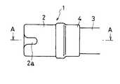
以下、図面を参照して本発明の実施の形態を説明する。図1乃至図6は本発明の第1の実施の形態に係り、図1は内視鏡先端部および内視鏡用フードの構成を示す側面図、図2は内視鏡先端部および内視鏡用フードの構造を示す断面図、図3は内視鏡用フードに高周波スネアを引っかけておく状態を示す説明図、図4は、内視鏡用フード内で粘膜等の組織を吸引してポリープ状にした状態を示す説明図、図5はポリープ状の粘膜等の基部に高周波スネアを位置させた状態を示す説明図、図6は高周波スネアを引っ張ってポリープ状の粘膜等の基部を締めつけた状態を示す説明図である。
【0007】
図2は、図1のAA断面の断面図となっている。図1および図2に示すように、内視鏡用フード1は、略円筒形状のキャップ2と、このキャップ2を内視鏡3の先端部に固定するための固定部材4とで構成されている。キャップ2と固定部材4は、圧入、接着剤での固定、ネジ等による結合固定、あるいは、より強固な固定を行う場合には超音波、溶剤等による固定方法を用いてもよい。
【0008】
キャップ2は、硬質で透明な合成樹脂、例えばアクリル樹脂や、好ましくはポリカーボネイト等の透明硬質のプラスチックで、あるいはガラス等で構成されており、内視鏡3の視野を妨げることなく、また、粘膜6(図4乃至図6)に押しつけたり吸引した時に、変形しない程度の硬さを有しており、また、その先端側から軸方向に延びるスリット2aを有している。スリット2aは、高周波スネアワイヤを挿通可能で、かつ、粘膜等の吸引時に空気モレが大きくならない程度の寸法を有しており、好ましくはスリット幅が0.5mm乃至4mm程度である。
【0009】
固定部材4は、合成樹脂や、好ましくは塩化ビニル、ポリウレタン、フッ素樹脂等の軟質プラスチック、又は弾性材料、好ましくは、ラテックス、シリコン、イソプレン、ネオプレン等のゴム類からなり、内視鏡3の先端部を傷つけることなく、キャップ2を内視鏡3に着脱自在となるように構成されている。
【0010】
次に、この実施の形態の作用を説明する。
まず、内視鏡3を患者の体腔内に挿入する前に、図3に示すように、内視鏡のチャンネル5内を挿通した可撓性管よりなるスネアシース7aと、このスネアシース7a内を進退自在に挿通され、かつ、その先端部をループ状に形成されたスネアワイヤ7bから成る高周波スネア7のスネアワイヤ7bのループ状部分をキャップ2に設けたスリット2aからキャップ2の外側に引き出し、キャップ2の外周部分に巻き付けた状態で引っかけておく。
【0011】
続いて、図4に示すように、内視鏡3の図示しない操作部を操作して、内視鏡用フード1のキャップ2の先端開口部を粘膜6の切除したい部位に移動させる。そして、その先端開口部を粘膜6に押しつけ、内視鏡3のチャンネル5を通して、図示しない吸引源から吸引することにより、粘膜6をキャップ2内に吸引して切除部分を盛り上げ、ポリープ状に形成する。
【0012】
次に、図5に示すように、スネアシース7aからスネアワイヤ7bを前方ヘ押し出して、スネアワイヤ7bをキャップ2から外し、吸引された粘膜6の基部へそのループ部を位置させる。
【0013】
更に、図6に示すように、スネアワイヤ7bをスネアシース7a内に引き込んで、粘膜6の基部を締めつけた後、スネアワイヤ7bに高周波電流を印加することによりポリープ状に形成した粘膜6の切除を実行する。
【0014】
本実施の形態によれば、従来内視鏡用フードの内側で粘膜6の切除部分の基部へスネアワイヤのループ部を位置させていた場合に比べ、内視鏡用フードの内側で粘膜6を吸引して盛り上げポリープ状にした切除部分に対して内視鏡用フードの外側でスネアワイヤのループ部を位置させるため、より根元側で切除が可能となり、より大きな粘膜の切除が可能となる。また、スネアワイヤ7bの操作も容易にすることができる。
【0015】
次に、本発明の第2の実施の形態を図7を参照して説明する。なお、第1の実施の形態と同一の構成要素には同一符号を付し、説明は省略する。
【0016】
図7において、キャップ2の先端部寄りの外周上には、キャップ2の外周よりさらに径の大きなスネアワイヤ係止部10が突出して設けられている。スネアワイヤ係止部10はその外周端面をR面で構成している。なお、外周端面は、必要に応じ任意の寸法の半径のR面、面取り等を選択、併用して構成することができる。また、スネアワイヤ係止部10は、必ずしも外周全周にわたって必須ではなく、その一部だけを外周上の少なくとも1ヶ所以上に配置してもよい。あるいは、略半球状もしくはそれに類似した形状の突起部を少なくとも1ヶ所以上設けるようにしてもよい。
【0017】
続いて、第2の実施の形態の作用を説明する。
第1の実施の形態と同様、内視鏡3を患者の体腔内に挿入する前に、高周波スネア7のスネアワイヤ7bのループ状部分をキャップ2に設けたスリット2aからキャップ2の外側に引き出し、キャップ2の外周部分に引っかけておく。この時、スネアワイヤ7bをスネアワイヤ係止部10に引っかけておく。
【0018】
本実施の形態によれば、スネアワイヤ7bをキャップ2に引っかけておく際、スネアワイヤ係止部10に引っかけておくため、内視鏡3の挿入時や観察時に、スネアワイヤ7bをキャップ2から外れて脱落しにくくすることができる。
【0019】
次に、本発明の第3の実施の形態を図8を参照して説明する。なお、第1の実施の形態と同一の構成要素には同一符号を付し、説明は省略する。
【0020】
図8において、キャップ2の先端部寄りの外周上には、溝部が形成され、スネアワイヤ係止部11を形成している。溝部は、R面となっている。なお、溝部は、必要に応じ任意の寸法の半径のR面、面取り等を選択、併用して構成することができる。また、スネアワイヤ係止部11は、必ずしも外周全周にわたって必須ではなく、その一部だけを外周上の少なくとも1ヶ所以上に配置してもよい。
【0021】
次に、第3の実施の形態の作用を説明する。
第1の実施の形態と同様、内視鏡3を患者の体腔内に挿入する前に、高周波スネア7のスネアワイヤ7bのループ状部分をキャップ2に設けたスリット2aからキャップ2の外側に引き出し、キャップ2の外周部分に引っかけておく。この時、スネアワイヤ7bをスネアワイヤ係止部11内に巻き付けた状態で引っかけておく。
【0022】
本実施の形態によれば、スネアワイヤ7bをキャップ2に引っかけておく際、スネアワイヤ係止部11内に引っかけておくため、内視鏡3の挿入時や観察時に、スネアワイヤ7bをキャップ2から外れて脱落しにくくすることができる。また、スネアワイヤ係止部11がキャップ2に対して凹部に構成されているので、患者の体腔内への挿入の際の抵抗が小さくなり、挿入が容易になり、患者の苦痛の軽減をはかることができる。
【0023】
以上詳述したように本発明の実施態様によれば、以下のような構成を得ることができる。
[付記項1]
略円筒形状で硬質で透明でかつその一端側端面から軸方向に沿って形成されたスリットを有するキャップと、前記キャップの他端を内視鏡先端部に固定するための固定部材と、からなる内視鏡用フード。
[付記項2]
略円筒形状で硬質で透明でかつその一端側端面から軸方向に沿って形成されたスリットを有するキャップと前記キャップの他端を内視鏡先端部に固定するための固定部材とからなり内視鏡先端部に取付けられた内視鏡用フードと、前記内視鏡のチャンネル内を挿通し前記内視鏡用フード内からスネアワイヤ先端のループ状部分を前記内視鏡用フードのスリットを挿通して引出して前記内視鏡用フードの外周に巻き付けた状態で引っかけられた高周波スネアワイヤと、を有することを特徴とする内視鏡用フードを使用した高周波処置装置。
[付記項3]
略円筒形状で硬質で透明でかつその一端側端面から軸方向に沿って形成されたスリットを有するキャップと前記キャップの他端を内視鏡先端部に固定するための固定部材とからなる内視鏡用フードを内視鏡先端部に取り付ける第1のステップと、前記内視鏡のチャンネル内に高周波スネアを挿通して内視鏡先端面から前記内視鏡用フード内に前記高周波スネアの先端を突出させる第2のステップと、前記第2のステップで突出させた高周波スネアのスネアワイヤ先端のループ状部分を前記内視鏡用フードのスリットを挿通して引出して前記内視鏡用フードの外周に巻き付けた状態で引っかける第3のステップと、を有することを特徴とする内視鏡用フードを使用した高周波処置具の装着方法。
[付記項4]
前記キャップの外周面上にこの外周面から突出したスネアワイヤ係止部を設けたことを特徴とする付記項1に記載の内視鏡用フード。
[付記項5]
前記キャップの外周面上に溝部からなるスネアワイヤ係止部を設けたことを特徴とする付記項1に記載の内視鏡用フード。
[付記項6]
前記内視鏡用フードのスリット幅は、0.5mm乃至4mmであることを特徴とする付記項1に記載の内視鏡用フード。
[付記項7]
前記キャップの外周面上にこの外周面から突出したスネアワイヤ係止部を設けたことを特徴とする付記項2に記載の内視鏡用フードを使用した高周波処置装置。
[付記項8]
前記キャップの外周面上に溝部からなるスネアワイヤ係止部を設けたことを特徴とする付記項2に記載の内視鏡用フードを使用した高周波処置装置。
[付記項9]
前記内視鏡用フードのスリット幅は、0.5mm乃至4mmであることを特徴とする付記項2に記載の内視鏡用フードを使用した高周波処置装置。
[付記項10]
前記高周波スネアのスネアシースからスネアワイヤを前方へ押し出すことによって前記高周波スネアワイヤが前記内視鏡用フード外周から外れるようになしたことを特徴とする付記項2に記載の内視鏡用フードを使用した高周波処置装置。
【0024】
【発明の効果】
以上説明したように本発明によれば、高周波スネアの操作が容易に行え、かつ、大きな粘膜等の切断も可能となる内視鏡用フードおよび内視鏡用フードを使用した高周波処置装置を提供することができる。
【図面の簡単な説明】
【図1】本発明の第1の実施の形態の内視鏡先端部および内視鏡用フードの構成を示す側面図。
【図2】本発明の第1の実施の形態の内視鏡先端部および内視鏡用フードの構造を示す
断面図。
【図3】本発明の第1の実施の形態の内視鏡用フードに高周波スネアワイヤを引っかけ
ておく状態を示す説明図。
【図4】本発明の第1の実施の形態の内視鏡用フード内で粘膜等の組織を吸引してポリ
ープ状にした状態を示す説明図。
【図5】本発明の第1の実施の形態のポリープ状の粘膜等の基部に高周波スネアワイヤ
を位置させた状態を示す説明図。
【図6】本発明の第1の実施の形態の高周波スネアワイヤを引っ張ってポリープ状の粘
膜等の基部を締めつけた状態を示す説明図。
【図7】本発明の第2の実施の形態の内視鏡先端部および内視鏡用フードの構成を示す
側面図。
【図8】本発明の第3の実施の形態の内視鏡先端部および内視鏡用フードの構成を示す
側面図。
【図9】従来の内視鏡用フード内でポリープ状の粘膜等の基部に高周波スネアワイヤを
位置させた状態を示す説明図。
【符号の説明】
1 内視鏡用フード
2 キャップ
2a スリット
3 内視鏡
4 固定部材
5 チャンネル
7 高周波スネア
7a スネアシース
7b スネアワイヤ[0001]
TECHNICAL FIELD OF THE INVENTION
The present invention relates to a substantially cylindrical endoscope hood attached to the distal end of an insertion portion of an endoscope in endoscopy or endoscopic surgery, a high-frequency treatment device using the endoscope hood, and mounting thereof. About the method.
[0002]
[Prior art]
In endoscopy and endoscopic surgery, mucous membranes are sucked into a substantially cylindrical hood attached to the end of the insertion section of the endoscope to form a polyp, and a high-frequency snare is used in the hood. A procedure for cutting a base such as a mucous membrane formed in a polyp shape may be performed. Conventionally, when performing such a treatment, as shown in FIG. 9, a high-frequency snare is operated in the
A hood-shaped device provided at the end of the endoscope is disclosed in, for example, Japanese Patent Application Laid-Open No. 61-191333.
[0003]
[Problems to be solved by the invention]
The operation of positioning a high-frequency snare at the base of a polyp-shaped mucous membrane or the like has been performed in a hood. However, this operation is difficult, requires skill, and the size of mucous membranes that can be cut is limited.
[0004]
The present invention has been made in view of the above circumstances, and has an endoscope hood and a high-frequency treatment using the endoscope hood in which a high-frequency snare can be easily operated and a large mucous membrane or the like can be cut. It is an object of the present invention to provide an apparatus and a mounting method thereof.
[0005]
[Means for Solving the Problems]
The present invention relates to an endoscope comprising: a cylindrical cap having a slit formed along an axial direction from an end face on one end side thereof; and a fixing member for fixing the other end of the cap to a distal end portion of the endoscope. An endoscope hood attached to a distal end portion, and a loop-shaped portion of a snare wire tip is inserted from the inside of the endoscope hood through a slit of the endoscope hood, and is pulled out of the endoscope hood. And a high-frequency snare wire wound in a state of being wound around the endoscope hood. In addition, a cap having a substantially cylindrical, hard, transparent, and slit formed along an axial direction from one end face of the end thereof, and a fixing member for fixing the other end of the cap to the endoscope distal end portion. An endoscope hood attached to an endoscope distal end portion, and a loop-shaped portion of a snare wire tip inserted from the inside of the endoscope hood through a slit of the endoscope hood and pulled out. A high-frequency treatment apparatus using an endoscope hood having a high-frequency snare wire wound around an outer periphery of the hood.
[0006]
BEST MODE FOR CARRYING OUT THE INVENTION
Hereinafter, embodiments of the present invention will be described with reference to the drawings. 1 to 6 relate to a first embodiment of the present invention. FIG. 1 is a side view showing the configuration of an endoscope distal end and an endoscope hood, and FIG. 2 is an endoscope distal end and endoscope. FIG. 3 is a cross-sectional view showing the structure of a mirror hood, FIG. 3 is an explanatory view showing a state in which a high-frequency snare is hooked on the endoscope hood, and FIG. FIG. 5 is an explanatory view showing a polyp-shaped state, FIG. 5 is an explanatory view showing a state in which a high-frequency snare is positioned on the base of a polyp-like mucous membrane, and FIG. It is explanatory drawing which shows the state which was turned.
[0007]
FIG. 2 is a cross-sectional view taken along the line AA of FIG. As shown in FIGS. 1 and 2, the endoscope hood 1 includes a substantially
[0008]
The
[0009]
The
[0010]
Next, the operation of this embodiment will be described.
First, before inserting the
[0011]
Subsequently, as shown in FIG. 4, by operating an operation unit (not shown) of the
[0012]
Next, as shown in FIG. 5, the
[0013]
Further, as shown in FIG. 6, after the
[0014]
According to the present embodiment, the
[0015]
Next, a second embodiment of the present invention will be described with reference to FIG. The same components as those in the first embodiment are denoted by the same reference numerals, and description thereof will be omitted.
[0016]
In FIG. 7, a snare wire locking portion 10 having a larger diameter than the outer circumference of the
[0017]
Next, the operation of the second embodiment will be described.
As in the first embodiment, before inserting the
[0018]
According to the present embodiment, when the
[0019]
Next, a third embodiment of the present invention will be described with reference to FIG. The same components as those in the first embodiment are denoted by the same reference numerals, and description thereof will be omitted.
[0020]
In FIG. 8, a groove is formed on the outer periphery of the
[0021]
Next, the operation of the third embodiment will be described.
As in the first embodiment, before inserting the
[0022]
According to the present embodiment, when the
[0023]
As described in detail above, according to the embodiment of the present invention, the following configuration can be obtained.
[Appendix 1]
A cap having a substantially cylindrical, hard, transparent, and slit having a slit formed along an axial direction from an end surface on one end side thereof, and a fixing member for fixing the other end of the cap to the endoscope distal end portion. Hood for endoscope.
[Appendix 2]
A cap having a substantially cylindrical, hard and transparent cap having a slit formed along an axial direction from an end face on one end side thereof, and a fixing member for fixing the other end of the cap to a distal end portion of the endoscope. An endoscope hood attached to the end of the endoscope and a channel of the endoscope are inserted through the loop of the snare wire tip from inside the endoscope hood through a slit of the endoscope hood. And a high-frequency snare wire wound around the outer periphery of the endoscope hood. The high-frequency snare wire is used in the high-frequency treatment apparatus using the endoscope hood.
[Appendix 3]
An endoscope comprising a substantially cylindrical, hard and transparent cap having a slit formed along an axial direction from an end surface on one end side thereof, and a fixing member for fixing the other end of the cap to a distal end portion of the endoscope. A first step of attaching a mirror hood to an endoscope distal end portion, and a high-frequency snare inserted into a channel of the endoscope and a distal end of the high-frequency snare inserted into the endoscope hood from an endoscope distal end surface; And a loop-shaped portion of the snare wire tip of the high-frequency snare protruded in the second step is inserted through a slit of the endoscope hood, and is pulled out to form an outer periphery of the endoscope hood. And a third step of hooking in a state of being wound around the high-frequency treatment instrument using the endoscope hood.
[Appendix 4]
2. The endoscope hood according to claim 1, wherein a snare wire engaging portion protruding from the outer peripheral surface is provided on the outer peripheral surface of the cap.
[Appendix 5]
2. The endoscope hood according to claim 1, wherein a snare wire engaging portion formed of a groove is provided on an outer peripheral surface of the cap.
[Appendix 6]
2. The endoscope hood according to claim 1, wherein a slit width of the endoscope hood is 0.5 mm to 4 mm.
[Appendix 7]
The high-frequency treatment apparatus using the hood for an endoscope according to
[Appendix 8]
3. The high-frequency treatment apparatus using the hood for an endoscope according to
[Appendix 9]
The high-frequency treatment apparatus using the endoscope hood according to
[Appendix 10]
The high-frequency wave using the endoscope hood according to
[0024]
【The invention's effect】
According to the present invention described above, the operation of the high-frequency snare is easy to, andprovide a high-frequency treatment apparatus using the endoscope hood and endoscope hood serving as a possible cutting of large mucous membranesit can be.
[Brief description of the drawings]
FIG. 1 is a side view showing a configuration of an endoscope tip and an endoscope hood according to a first embodiment of the present invention.
FIG. 2 is a cross-sectional view showing the structure of an endoscope tip and an endoscope hood according to the first embodiment of the present invention.
FIG. 3 is an explanatory diagram showing a state in which a high-frequency snare wire is hooked on the endoscope hood according to the first embodiment of the present invention.
FIG. 4 is an explanatory view showing a state in which a tissue such as a mucous membrane is sucked into a polyp shape in the endoscope hood according to the first embodiment of the present invention.
FIG. 5 is an explanatory diagram showing a state in which a high-frequency snare wire is positioned on a base such as a polyp-like mucous membrane according to the first embodiment of the present invention.
FIG. 6 is an explanatory view showing a state in which the high-frequency snare wire according to the first embodiment of the present invention is pulled to tighten a base such as a polyp-shaped mucous membrane.
FIG. 7 is a side view showing a configuration of an endoscope distal end portion and an endoscope hood according to a second embodiment of the present invention.
FIG. 8 is a side view showing a configuration of an endoscope tip and an endoscope hood according to a third embodiment of the present invention.
FIG. 9 is an explanatory diagram showing a state in which a high-frequency snare wire is located at a base of a polyp-like mucous membrane or the like in a conventional endoscope hood.
[Explanation of symbols]
DESCRIPTION OF SYMBOLS 1
Claims (2)
Translated fromJapanesePriority Applications (1)
| Application Number | Priority Date | Filing Date | Title |
|---|---|---|---|
| JP22627995AJP3587594B2 (en) | 1995-09-04 | 1995-09-04 | High-frequency treatment device using endoscope hood |
Applications Claiming Priority (1)
| Application Number | Priority Date | Filing Date | Title |
|---|---|---|---|
| JP22627995AJP3587594B2 (en) | 1995-09-04 | 1995-09-04 | High-frequency treatment device using endoscope hood |
Publications (2)
| Publication Number | Publication Date |
|---|---|
| JPH0966019A JPH0966019A (en) | 1997-03-11 |
| JP3587594B2true JP3587594B2 (en) | 2004-11-10 |
Family
ID=16842728
Family Applications (1)
| Application Number | Title | Priority Date | Filing Date |
|---|---|---|---|
| JP22627995AExpired - Fee RelatedJP3587594B2 (en) | 1995-09-04 | 1995-09-04 | High-frequency treatment device using endoscope hood |
Country Status (1)
| Country | Link |
|---|---|
| JP (1) | JP3587594B2 (en) |
Families Citing this family (17)
| Publication number | Priority date | Publication date | Assignee | Title |
|---|---|---|---|---|
| US5897487A (en)* | 1997-04-15 | 1999-04-27 | Asahi Kogaku Kogyo Kabushiki Kaisha | Front end hood for endoscope |
| JPH11299725A (en) | 1998-04-21 | 1999-11-02 | Olympus Optical Co Ltd | Hood for endoscope |
| JP2002112946A (en)* | 2000-10-11 | 2002-04-16 | Olympus Optical Co Ltd | Hood for endoscope |
| JP3722729B2 (en) | 2001-06-04 | 2005-11-30 | オリンパス株式会社 | Endoscope treatment device |
| JP3826045B2 (en)* | 2002-02-07 | 2006-09-27 | オリンパス株式会社 | Endoscope hood |
| JP4391765B2 (en) | 2002-12-02 | 2009-12-24 | オリンパス株式会社 | Endoscopic mucosal resection tool |
| JP4441227B2 (en) | 2003-10-08 | 2010-03-31 | Hoya株式会社 | Endoscope for high frequency treatment |
| JP4495438B2 (en) | 2003-10-14 | 2010-07-07 | Hoya株式会社 | Endoscopic high-frequency treatment instrument |
| US7351201B2 (en) | 2003-12-19 | 2008-04-01 | Pentax Corporation | Treatment instrument for endoscope |
| JP2006192086A (en)* | 2005-01-14 | 2006-07-27 | Pentax Corp | End of endoscope for large intestine insertion |
| US20070203395A1 (en)* | 2006-02-28 | 2007-08-30 | Takayasu Mikkaichi | Cap installable on distal end portion of endoscope |
| JP5285050B2 (en)* | 2010-11-24 | 2013-09-11 | オリンパス株式会社 | Endoscope hood |
| CN102416211A (en)* | 2011-09-13 | 2012-04-18 | 中国人民解放军第四军医大学 | Transparent cap for injecting esophageal vein sclerosing agent under endoscope |
| US9155554B2 (en) | 2011-10-27 | 2015-10-13 | Boston Scientific Scimed, Inc. | Tissue resection bander and related methods of use |
| US9204782B2 (en) | 2011-10-27 | 2015-12-08 | Boston Scientific Scimed, Inc. | Mucosal resection device and related methods of use |
| EP3442396B1 (en) | 2016-07-01 | 2020-03-11 | Boston Scientific Scimed Inc. | Device for engaging of medical tools |
| KR102045383B1 (en)* | 2017-07-28 | 2019-11-15 | (재)예수병원유지재단 | Overtube |
- 1995
- 1995-09-04JPJP22627995Apatent/JP3587594B2/ennot_activeExpired - Fee Related
Also Published As
| Publication number | Publication date |
|---|---|
| JPH0966019A (en) | 1997-03-11 |
Similar Documents
| Publication | Publication Date | Title |
|---|---|---|
| JP3587594B2 (en) | High-frequency treatment device using endoscope hood | |
| JP3902290B2 (en) | Endoscope ligature | |
| JP3533163B2 (en) | Endoscope tip | |
| JP3017451B2 (en) | Hood for endoscope | |
| JP3826045B2 (en) | Endoscope hood | |
| JP2005131211A (en) | Externally mounted channel for endoscope | |
| US20140228839A1 (en) | Swivel device for improved surgical smoke evacuation | |
| JP4009350B2 (en) | Endoscope system | |
| JPH07265329A (en) | Puncture high frequency treatment device | |
| JP2009082536A (en) | Endoscope ligation tool and endoscope ligation system | |
| JPH08131397A (en) | Hood for endoscope | |
| JP3514410B2 (en) | Endoscopic ligation kit | |
| US20090182198A1 (en) | Multiple band dispenser endoscope sheath | |
| CN119699982B (en) | Front end assembly, insertion part and endoscope | |
| JPH07163516A (en) | Guide tube | |
| JPH119610A (en) | Endoscope cautery | |
| JP2003204919A (en) | Hood for endoscope | |
| JP2024128090A (en) | Systems and methods for removal of endoscopic devices | |
| JPH07184830A (en) | Endoscope cover type endoscope apparatus | |
| JP4217334B2 (en) | Endoscopic treatment device and high-frequency treatment tool thereof | |
| JP2005245737A (en) | Puncture instrument | |
| JP2005323886A (en) | Ultrasonic endoscope | |
| JP2002224129A (en) | Trocar fixing tool | |
| JPH10328203A (en) | Endoscope cautery | |
| JP2005168927A (en) | Diathermic knife |
Legal Events
| Date | Code | Title | Description |
|---|---|---|---|
| A02 | Decision of refusal | Free format text:JAPANESE INTERMEDIATE CODE: A02 Effective date:20040316 | |
| A521 | Written amendment | Free format text:JAPANESE INTERMEDIATE CODE: A523 Effective date:20040415 | |
| A911 | Transfer of reconsideration by examiner before appeal (zenchi) | Free format text:JAPANESE INTERMEDIATE CODE: A911 Effective date:20040524 | |
| TRDD | Decision of grant or rejection written | ||
| A01 | Written decision to grant a patent or to grant a registration (utility model) | Free format text:JAPANESE INTERMEDIATE CODE: A01 Effective date:20040803 | |
| A61 | First payment of annual fees (during grant procedure) | Free format text:JAPANESE INTERMEDIATE CODE: A61 Effective date:20040810 | |
| FPAY | Renewal fee payment (event date is renewal date of database) | Free format text:PAYMENT UNTIL: 20080820 Year of fee payment:4 | |
| FPAY | Renewal fee payment (event date is renewal date of database) | Free format text:PAYMENT UNTIL: 20090820 Year of fee payment:5 | |
| FPAY | Renewal fee payment (event date is renewal date of database) | Free format text:PAYMENT UNTIL: 20100820 Year of fee payment:6 | |
| FPAY | Renewal fee payment (event date is renewal date of database) | Free format text:PAYMENT UNTIL: 20100820 Year of fee payment:6 | |
| FPAY | Renewal fee payment (event date is renewal date of database) | Free format text:PAYMENT UNTIL: 20110820 Year of fee payment:7 | |
| FPAY | Renewal fee payment (event date is renewal date of database) | Free format text:PAYMENT UNTIL: 20120820 Year of fee payment:8 | |
| FPAY | Renewal fee payment (event date is renewal date of database) | Free format text:PAYMENT UNTIL: 20130820 Year of fee payment:9 | |
| LAPS | Cancellation because of no payment of annual fees |