JP3584913B2 - Data output method, recording method and apparatus, reproduction method and apparatus, data transmission method and reception method - Google Patents
Data output method, recording method and apparatus, reproduction method and apparatus, data transmission method and reception methodDownload PDFInfo
- Publication number
- JP3584913B2 JP3584913B2JP2001289982AJP2001289982AJP3584913B2JP 3584913 B2JP3584913 B2JP 3584913B2JP 2001289982 AJP2001289982 AJP 2001289982AJP 2001289982 AJP2001289982 AJP 2001289982AJP 3584913 B2JP3584913 B2JP 3584913B2
- Authority
- JP
- Japan
- Prior art keywords
- data
- converted
- sector
- unit
- start code
- Prior art date
- Legal status (The legal status is an assumption and is not a legal conclusion. Google has not performed a legal analysis and makes no representation as to the accuracy of the status listed.)
- Expired - Fee Related
Links
- 238000000034methodMethods0.000titleclaimsdescription109
- 230000005540biological transmissionEffects0.000titleclaimsdescription19
- 238000012545processingMethods0.000claimsdescription31
- 238000006243chemical reactionMethods0.000claimsdescription21
- 238000001514detection methodMethods0.000claimsdescription18
- 230000008569processEffects0.000claimsdescription5
- 230000003287optical effectEffects0.000description34
- 101000969688Homo sapiens Macrophage-expressed gene 1 proteinProteins0.000description26
- 102100021285Macrophage-expressed gene 1 proteinHuman genes0.000description26
- 238000010586diagramMethods0.000description9
- 238000012937correctionMethods0.000description8
- 239000000463materialSubstances0.000description4
- 239000000758substrateSubstances0.000description4
- 230000008859changeEffects0.000description3
- 230000006835compressionEffects0.000description2
- 238000007906compressionMethods0.000description2
- 238000013478data encryption standardMethods0.000description2
- 238000001746injection mouldingMethods0.000description2
- 230000001678irradiating effectEffects0.000description2
- 229920002120photoresistant polymerPolymers0.000description2
- 239000004417polycarbonateSubstances0.000description2
- 229920000515polycarbonatePolymers0.000description2
- 230000003044adaptive effectEffects0.000description1
- 230000008901benefitEffects0.000description1
- 238000004891communicationMethods0.000description1
- 230000000694effectsEffects0.000description1
- 238000005323electroformingMethods0.000description1
- 230000006870functionEffects0.000description1
- 230000004927fusionEffects0.000description1
- 239000011521glassSubstances0.000description1
- 239000011159matrix materialSubstances0.000description1
- 238000012986modificationMethods0.000description1
- 230000004048modificationEffects0.000description1
- 238000004544sputter depositionMethods0.000description1
- 238000012546transferMethods0.000description1
Images


Classifications
- H—ELECTRICITY
- H04—ELECTRIC COMMUNICATION TECHNIQUE
- H04N—PICTORIAL COMMUNICATION, e.g. TELEVISION
- H04N9/00—Details of colour television systems
- H04N9/79—Processing of colour television signals in connection with recording
- H04N9/7921—Processing of colour television signals in connection with recording for more than one processing mode
- G—PHYSICS
- G11—INFORMATION STORAGE
- G11B—INFORMATION STORAGE BASED ON RELATIVE MOVEMENT BETWEEN RECORD CARRIER AND TRANSDUCER
- G11B20/00—Signal processing not specific to the method of recording or reproducing; Circuits therefor
- G11B20/00086—Circuits for prevention of unauthorised reproduction or copying, e.g. piracy
- G11B20/0021—Circuits for prevention of unauthorised reproduction or copying, e.g. piracy involving encryption or decryption of contents recorded on or reproduced from a record carrier
- G11B20/00217—Circuits for prevention of unauthorised reproduction or copying, e.g. piracy involving encryption or decryption of contents recorded on or reproduced from a record carrier the cryptographic key used for encryption and/or decryption of contents recorded on or reproduced from the record carrier being read from a specific source
- G11B20/00253—Circuits for prevention of unauthorised reproduction or copying, e.g. piracy involving encryption or decryption of contents recorded on or reproduced from a record carrier the cryptographic key used for encryption and/or decryption of contents recorded on or reproduced from the record carrier being read from a specific source wherein the key is stored on the record carrier
- G11B20/00333—Circuits for prevention of unauthorised reproduction or copying, e.g. piracy involving encryption or decryption of contents recorded on or reproduced from a record carrier the cryptographic key used for encryption and/or decryption of contents recorded on or reproduced from the record carrier being read from a specific source wherein the key is stored on the record carrier the key being stored in header data, e.g. in sector headers
- G—PHYSICS
- G11—INFORMATION STORAGE
- G11B—INFORMATION STORAGE BASED ON RELATIVE MOVEMENT BETWEEN RECORD CARRIER AND TRANSDUCER
- G11B20/00—Signal processing not specific to the method of recording or reproducing; Circuits therefor
- G11B20/00086—Circuits for prevention of unauthorised reproduction or copying, e.g. piracy
- G11B20/0021—Circuits for prevention of unauthorised reproduction or copying, e.g. piracy involving encryption or decryption of contents recorded on or reproduced from a record carrier
- G11B20/00485—Circuits for prevention of unauthorised reproduction or copying, e.g. piracy involving encryption or decryption of contents recorded on or reproduced from a record carrier characterised by a specific kind of data which is encrypted and recorded on and/or reproduced from the record carrier
- G11B20/00492—Circuits for prevention of unauthorised reproduction or copying, e.g. piracy involving encryption or decryption of contents recorded on or reproduced from a record carrier characterised by a specific kind of data which is encrypted and recorded on and/or reproduced from the record carrier wherein content or user data is encrypted
- G11B20/00507—Circuits for prevention of unauthorised reproduction or copying, e.g. piracy involving encryption or decryption of contents recorded on or reproduced from a record carrier characterised by a specific kind of data which is encrypted and recorded on and/or reproduced from the record carrier wherein content or user data is encrypted wherein consecutive physical data units of the record carrier are encrypted with separate encryption keys, e.g. the key changes on a cluster or sector basis
- G—PHYSICS
- G11—INFORMATION STORAGE
- G11B—INFORMATION STORAGE BASED ON RELATIVE MOVEMENT BETWEEN RECORD CARRIER AND TRANSDUCER
- G11B20/00—Signal processing not specific to the method of recording or reproducing; Circuits therefor
- G11B20/10—Digital recording or reproducing
- H—ELECTRICITY
- H04—ELECTRIC COMMUNICATION TECHNIQUE
- H04N—PICTORIAL COMMUNICATION, e.g. TELEVISION
- H04N21/00—Selective content distribution, e.g. interactive television or video on demand [VOD]
- H04N21/40—Client devices specifically adapted for the reception of or interaction with content, e.g. set-top-box [STB]; Operations thereof
- H04N21/41—Structure of client; Structure of client peripherals
- H04N21/426—Internal components of the client ; Characteristics thereof
- H04N21/42646—Internal components of the client ; Characteristics thereof for reading from or writing on a non-volatile solid state storage medium, e.g. DVD, CD-ROM
- H—ELECTRICITY
- H04—ELECTRIC COMMUNICATION TECHNIQUE
- H04N—PICTORIAL COMMUNICATION, e.g. TELEVISION
- H04N21/00—Selective content distribution, e.g. interactive television or video on demand [VOD]
- H04N21/40—Client devices specifically adapted for the reception of or interaction with content, e.g. set-top-box [STB]; Operations thereof
- H04N21/43—Processing of content or additional data, e.g. demultiplexing additional data from a digital video stream; Elementary client operations, e.g. monitoring of home network or synchronising decoder's clock; Client middleware
- H04N21/438—Interfacing the downstream path of the transmission network originating from a server, e.g. retrieving encoded video stream packets from an IP network
- H04N21/4385—Multiplex stream processing, e.g. multiplex stream decrypting
- H04N21/43853—Multiplex stream processing, e.g. multiplex stream decrypting involving multiplex stream decryption
- H—ELECTRICITY
- H04—ELECTRIC COMMUNICATION TECHNIQUE
- H04N—PICTORIAL COMMUNICATION, e.g. TELEVISION
- H04N5/00—Details of television systems
- H04N5/76—Television signal recording
- H04N5/91—Television signal processing therefor
- H04N5/913—Television signal processing therefor for scrambling ; for copy protection
- H04N2005/91357—Television signal processing therefor for scrambling ; for copy protection by modifying the video signal
- H04N2005/91364—Television signal processing therefor for scrambling ; for copy protection by modifying the video signal the video signal being scrambled
- H—ELECTRICITY
- H04—ELECTRIC COMMUNICATION TECHNIQUE
- H04N—PICTORIAL COMMUNICATION, e.g. TELEVISION
- H04N5/00—Details of television systems
- H04N5/76—Television signal recording
- H04N5/84—Television signal recording using optical recording
- H04N5/85—Television signal recording using optical recording on discs or drums
- H—ELECTRICITY
- H04—ELECTRIC COMMUNICATION TECHNIQUE
- H04N—PICTORIAL COMMUNICATION, e.g. TELEVISION
- H04N9/00—Details of colour television systems
- H04N9/79—Processing of colour television signals in connection with recording
- H04N9/80—Transformation of the television signal for recording, e.g. modulation, frequency changing; Inverse transformation for playback
- H04N9/804—Transformation of the television signal for recording, e.g. modulation, frequency changing; Inverse transformation for playback involving pulse code modulation of the colour picture signal components
- H04N9/8042—Transformation of the television signal for recording, e.g. modulation, frequency changing; Inverse transformation for playback involving pulse code modulation of the colour picture signal components involving data reduction
Landscapes
- Engineering & Computer Science (AREA)
- Signal Processing (AREA)
- Computer Security & Cryptography (AREA)
- Multimedia (AREA)
- Theoretical Computer Science (AREA)
- Signal Processing For Digital Recording And Reproducing (AREA)
- Television Signal Processing For Recording (AREA)
- Storage Device Security (AREA)
- Compression Or Coding Systems Of Tv Signals (AREA)
Description
Translated fromJapanese【0001】
【発明の属する技術分野】
この発明は、異なるデータフォーマットを融合するようにしたデータ出力方法、記録方法および装置、再生方法および装置、データ送信方法および受信方法に関する。
【0002】
【従来の技術】
パーソナルコンピュータの外部記憶装置としてのハードディスクドライブ、フロッピー(登録商標)ディスクドライブ、CD−ROM/CD−R/CD−RWドライブ等では、セクタ単位でデータが処理される。例えばセクタサイズは、2Kバイト(2048バイト)である。コンテンツの著作権を保護するために、コンテンツデータを暗号化して記録することがなされる。セクタ単位で暗号化する、暗号化しないを制御しようとすると、セクタ毎に暗号化制御ビットが必要とされる。また、CBC(Chaining Block Ciphering)モードのために、IV(Initial
Vector:暗号化の初期値)が必要となる。
【0003】
マルチメディアコンテンツの伝送または記録フォーマットとしてMPEG(Moving Picture Experts Group)が知られている。図1Aは、MPEG2システムのプログラムストリームのデータ構成を示す。1つのプログラムは、先頭のパックヘッダから終了コードまでである。一般的に、パックは、複数のパケットから構成されている。先頭のパックには、システムヘッダが付加される。2番目以降のパケットに対して、システムヘッダを付加することは、オプションとされている。各パックに対して先頭にパックヘッダが付加されている。
【0004】
図1Aに示すように、パックヘッダは、パック開始コード(32ビット)、識別コード(2ビット)、SCR(System Clock Reference:システム時刻基準参照値)(42+4ビット)、このストリームのビットレートを示す多重化レート(22+2ビット)、スタッフィング長(3+8ビット)、スタッフィングバイト(8×Mビット)によって構成される。スタッフィングバイトは、例えばパケットデータ長を一定とするために、使用されるダミーデータであり、意味のある情報を有していない。
【0005】
図1Bは、パケットの構成を示す。先頭に位置するパケット開始コード(32ビット)は、先頭開始コード(24ビット)とストリームID(8ビット)からなる。次に、パケットのデータ長を示すパケット長(16ビット)が位置する。2ビットの制御コードは、MPEG2システムでは、”01”とされる。フラグと制御(14ビット)の先頭の2ビットがPES(Packetized Elementary Stream)スクランブル制御に使用される。PESヘッダ長(8ビット)によって、ヘッダ長が示される。フラグと制御に対応してコンディショナル・コーディングされた項目には、PTS(Presentation Time Stamp)(33+7ビット) 、DTS(Decoding Time Stamp)(33+7ビット)、その他のコードが含まれている。さらに、スタッフィングバイト(8×Mビット)が付加され、その後に、パケットデータ(8×Nビット)が続いている。
【0006】
図2は、2Kバイト(2048バイト)をセクタ長とする、一般的なアプリケーションにおけるデータフォーマット(以下、一般データフォーマットと適宜称する)との融合を図るために、MPEG2システムにおけるデータ構成を2Kバイトに区切ったものを示す。図2に示すように、1パックが1パケットから構成される。1パックのサイズが2Kバイトとされる。したがって、1パックが一般フォーマットの1セクタに相当する。1パックの先頭に、パックヘッダ(14バイト)が位置し、以下、PESヘッダ(14バイト)、ストリームヘッダ(4バイト)、ユーザデータ(2016バイト)が順に配置される。ユーザデータを8バイト単位で区切ると、ユーザ(またはパケット)データは、D1からD252までのデータからなる。ユーザデータは、例えば圧縮符号化および暗号化がされたオーディオデータである。このような図2に示すデータ構成は、MPEG2システムの符号化規則を満たしている。
【0007】
パックヘッダは、図1Aに示したものと同様のものであるが、スタッフィングバイトを付加せず、14バイトの長さとしている。すなわち、パックヘッダは、パック開始コード(32ビット)、制御コード(2ビット)、SCR(42+4ビット)、このストリームのビットレートを示す多重化レート(22+2ビット)、スタッフィング長(3+8ビット)の合計112ビット(=14バイト)によって構成される。スタッフィングバイトを付加しない理由は、スタッフィングバイトによって、スクランブル制御ビットの位置が変動することを避けるためである。
【0008】
PESヘッダは、図1Bに示したものと同様のものであるが、パケット開始コード(32ビット)から、パケット長(16ビット)、2ビットの制御コード、フラグと制御(14ビット)、PESヘッダ長(8ビット)、PTS(33+7ビット)までの合計112ビット(=14バイト)を使用する。
【0009】
ストリームヘッダ(4バイト)には、オーディオの符号化方法(リニアPCM、MP3(MPEG1 Audio Layer III) 、AAC(Advanced Audio Coding) 、ATRAC3(Adaptive Transfer Acoustic Coding 3) 等)を示す情報、ビットレート(64Kbps等)の情報、チャンネル数(モノラル、ステレオ、5.1チャンネル等)の情報などが記録される。
【0010】
パックヘッダ、PESヘッダおよびストリームヘッダの32バイト(=256バイト)に対して、ビットの位置を規定するために、ビット番号を付加する。先頭のビットをビット0とすると、パックヘッダがビット0からビット111で構成され、PESヘッダがビット112からビット223となり、ストリームヘッダがビット223からビット255となる。PESヘッダでは、フラグと制御に含まれるスクランブル制御ビットの位置がビット162および163となる。スクランブル制御ビットは、”00”がスクランブルなし、”01”がスクランブルあり、”10”および”11”がリザーブド(未定義)である。
【0011】
また、パックヘッダ内のビット32およびビット33の2ビットの制御コードは、MPEG1システムでは、”00”であり、MPEG2システムでは、”01”である。なお、MPEG1システムの場合、スクランブル制御ビットはない。暗号化に必要なIVは、パックヘッダ内のSCR、PESヘッダ内のPTS等が使用される。
【0012】
図3Aは、一般データフォーマット(MPEGシステム以外の一般的なアプリケーションにおけるデータフォーマットを意味する)の1セクタのデータ構成を示す。CBC(Chaining Block Ciphering)モードでIV付きの暗号化(通常、8バイト単位の処理が多い)を仮定すると、先頭の8バイトにスクランブル制御、IV等が含まれる。例えば4バイトがIVとして使用される。セクタヘッダを除いた2040バイトがユーザデータである。したがって、ユーザデータは、2040バイトとなり、8バイト単位に区切ると、D1からD255までのデータが含まれる。
【0013】
【発明が解決しようとする課題】
上述したMPEG2システムのデータフォーマットと、図3Aに示す一般データフォーマットの両者を例えばパーソナルコンピュータ、光ディスクドライブ、アプリケーションソフトウェア(以下、ドライブ等と称する)で扱うことができることが望ましい。例えば一般アプリケーションのデータは、一般データフォーマットで扱い、オーディオ、ビデオデータをMPEG2システムのデータで扱うようになされる。オーディオ、ビデオデータをMPEG2システムのデータフォーマットとすることによって、オーディオデータおよびビデオデータを多重化でき、例えば音声と共に歌詞の画像を記録することができる。また、タイムスタンプである、PTSを利用することによって、可変長圧縮符号化を行なっている場合でも、高速アクセスが可能となる。
【0014】
二つの異なるデータフォーマットを使用する場合、ドライブ等が両者を識別して切り替える方法が考えられる。この方法は、ドライブ等が二つのフォーマットを識別するのが難しい。また、セクタ単位で暗号化されているか否かを識別するのに、MPEG2システムと一般データフォーマットでは、異なる位置のビットを見なくてはならず、セクタ単位の暗号化の有無の判別が困難である。
【0015】
他の方法は、二つの異なるデータフォーマットを融合するものである。この場合では、切替に伴う問題が生じない。図3Bは、一般データフォーマットをMPEG2システムに合わせた場合のデータ構成を示す。先頭の32バイトは、MPEG2システムの場合では、図2Aに示すようなパックヘッダ、PESヘッダ、ストリームヘッダである。一般データフォーマットのセクタヘッダ(8バイト)の持つ情報(スクランブル制御のビットおよびIV)は、32バイトが持つことができる。しかしながら、一般データフォーマットでは、8バイトのヘッダで良かったのが、32バイトを必要とするために、(32−8=24バイト)が無駄になる問題がある。言い換えると、1セクタのユーザデータが2040バイトから2016バイトに減少する問題が生じる。さらに、MPEG2システムにおけるスクランブル制御ビットの位置を固定化するために、スタッフィングバイトを使用できない問題があった。
【0016】
一方、MPEG2システムを一般データフォーマットに合わせると、図3Cに示すように、MPEG2システムのデータフォーマットの1セクタの先頭に8バイトのヘッダを付加するようになされる。その結果、MPEG2システム以外のアプリケーションでは問題がないが、MPEG2システムのアプリケーションでは、先頭の8バイトが無駄になる問題がある。
【0017】
したがって、この発明の目的は、無駄なデータが生じ、ユーザデータが減少する問題を回避して、異なるシステムのデータ構成を融合することができるデータ出力方法、記録方法および装置、再生方法および装置、データ送信方法および受信方法を提供することになる。
【0018】
【課題を解決するための手段】
上述した課題を解決するために、請求項1の発明は、入力されたデータを開始コードと開始コードに続く2ビットのうちの少なくとも1ビットが暗号化制御を示すビットであるヘッダが先頭に付加された1セクタ単位のデータに変換し、変換されたデータを暗号化する場合には、開始コードに続く2ビットのうちの少なくとも1ビットをデータが暗号化されていることを示すように設定し、変換されたデータを暗号化し、暗号化されたデータをエンコードして出力するデータ出力方法である。
【0019】
請求項8の発明は、入力されたデータを開始コードと開始コードに続く2ビットのうちの少なくとも1ビットが暗号化制御を示すビットであるヘッダが先頭に付加された1セクタ単位のデータに変換し、変換されたデータを暗号化する場合には、開始コードに続く2ビットのうちの少なくとも1ビットをデータが暗号化されていることを示すように設定し、変換されたデータを暗号化し、暗号化されたデータに記録のためのエンコード処理を施して記録媒体に記録する記録方法である。
【0020】
請求項15の発明は、入力されたデータを開始コードと開始コードに続く2ビットのうちの少なくとも1ビットが暗号化制御を示すビットであるヘッダが先頭に付加された1セクタ単位のデータに変換する変換部と、変換部によって変換されたデータを暗号化する場合には、開始コードに続く2ビットのうちの少なくとも1ビットをデータが暗号化されていることを示すように設定する設定部と、設定部からの出力データに暗号化処理を施す暗号化処理部と、暗号化処理部からの出力データに記録のためのエンコード処理を施すエンコード処理部と、エンコード処理部からの出力データを記録媒体に記録する記録部とを備えている記録装置である。
【0021】
請求項22の発明は、ユーザデータと開始コードと開始コードに続く2ビットのうちの少なくとも1ビットが暗号化制御を示すビットであるヘッダが先頭に付加された1セクタ単位のデータが記録された記録媒体から読み出されたデータをデコードし、デコードされたデータの開始コードに続く2ビットのうちの少なくとも1ビットを検出し、検出した結果、デコードされたデータが暗号化されているときには暗号を解読し、解読されたデータを1セクタ単位のデータから所定のデータ単位のデータに変換し出力する再生方法である。
【0022】
請求項29の発明は、ユーザデータと開始コードと開始コードに続く2ビットのうちの少なくとも1ビットが暗号化制御を示すビットであるヘッダが先頭に付加された1セクタ単位のデータが記録された記録媒体から読み出されたデータをデコードするデコーダと、デコーダからの出力データの開始コードに続く2ビットのうちの少なくとも1ビットを検出する検出部と、検出部による検出の結果、デコードされたデータが暗号化されているときにはデコーダからの出力データの暗号を解読する解読部と、解読部からの出力データを1セクタ単位のデータから所定のデータ単位のデータに変換して出力する変換部とを備えている再生装置である。
【0023】
請求項36の発明は、入力されたデータを開始コードと開始コードに続く2ビットのうちの少なくとも1ビットが暗号化制御を示すビットであるヘッダが先頭に付加された1セクタ単位のデータに変換し、変換されたデータを暗号化する場合には、開始コードに続く2ビットのうちの少なくとも1ビットをデータが暗号化されていることを示すように設定し、変換されたデータを暗号化し、暗号化されたデータに送信のためのエンコード処理を施して送信するデータ送信方法である。
【0024】
請求項43の発明は、ユーザデータと開始コードと開始コードに続く2ビットのうちの少なくとも1ビットが暗号化制御を示すビットであるヘッダが先頭に付加された1セクタ単位のデータを受信し、受信したデータをデコードし、デコードされたデータの開始コードに続く2ビットのうちの少なくとも1ビットを検出し、検出した結果、デコードされたデータが暗号化されているときには暗号を解読し、解読されたデータを1セクタ単位のデータから所定のデータ単位のデータに変換し出力するデータ受信方法である。
【0030】
所定位置の2ビットを暗号化制御に使用することによって、無駄なデータを生じさせず、且つ矛盾なく、二つの異なるシステム、例えばMPEG2システムと一般アプリケーションとを融合できる。然も、セクタ単位の暗号化制御が可能である。また、スクランブル制御ビットが規定されていない、MPEG1システムであっても、暗号化制御が可能となり、MPEG1のコンテンツのセキュリティを保護できる。暗号化の初期値が各データフォーマットで同一の位置に配置されているので、同じ暗号化システムによる暗号化が可能となる。暗号化が復号された後では、MPEG1およびMPEG2のシステムとして使用できる。MPEGシステムでスタッフィングバイトの前の固定位置に暗号化制御のビットを配置するので、スタッフィングバイトを使用することができる。
【0031】
【発明の実施の形態】
以下、この発明の一実施形態について説明する。最初に、図4を参照してこの一実施形態におけるデータフォーマットを説明する。図4Aは、1セクタを2Kバイト(2048バイト)とした例である。但し、2Kバイトは、一例であって、1セクタを2Kバイト以外としても良い。1セクタの先頭の8バイト(ビット0からビット63)の内で、ビット32のビット(a1とする)とビット33のビット(a2とする)の2ビットを暗号化制御に使用する。この2ビットと残りの30ビットの合計32ビットをIVとして利用する。ビット64以降のデータがIVを使用してCBCモードで暗号化される。但し、ビット64に限定されずに、ビット64以降の任意のビット以降のデータ例えばビット128以降のデータを暗号化しても良い。
【0032】
図4Bは、MPEG2システムに対してこの発明を適用した場合のデータ構成の一部を示す。すなわち、図2を参照して説明したように、先頭の32ビットがパック開始コードに相当し、次に、制御コード(a1およびa2)が配置され、その後に(42+2)ビットのSCRで配置される。したがって、制御コードがスクランブル制御にも使用され、IVがSCRの30ビットによって構成される。ビット64以降のデータがIVを使用して暗号化される。ユーザデータのサイズは、図2の場合と同様に、2016バイトである。
【0033】
MPEG2システムでは、ビット162および163にスクランブル制御ビットが配置され、スクランブル制御ビットは、”00”がスクランブルなし、”01”がスクランブルあり、”10”および”11”がリザーブド(未定義)とされている。一実施形態のように、制御コード(a1およびa2)を暗号化制御に使用する場合、制御コードの情報とスクランブル制御ビットの情報とが矛盾しないものとされる。
【0034】
図4Cは、MPEG以外の一般データフォーマットに対してこの発明を適用した例である。先頭の32ビットがリザーブドまたはシステムヘッダとして使用される。その次に2ビットの制御コードa1およびa2が配置され、残りの30ビットがハードウエアまたはソフトウェアによって生成された乱数とされる。制御コードと乱数がIVに相当する。但し、IVとして64ビットの長さが必要な場合では、ビット32からビット63までの32ビットを2度繰り返したデータ、またはビット0からビット63までのデータを使用するようにしても良い。ビット64以降がユーザデータとなり、ユーザデータのサイズは、図3Aに示すデータ構成と同様に、2040バイトとなる。
【0035】
図5は、2ビットの制御コード(a1およびa2)の定義の一例および他の例を示す。図5Aに示す例では、MPEG1とMPEG2の識別のために2ビットが使用される。”a1 a2” =”00”がMPEG1システムで暗号化なしと定義され、”a1 a2” =”01”がMPEG2システムで暗号化なしと定義されている。これは、MPEGの定義と一致している。”a1 a2” =”10”がMPEG1システムで暗号化ありと定義され、”a1 a2” =”11”がMPEG2システムで暗号化ありと定義される。なお、MPEG1システムが使用されない時には、”a1 a2” =”00”および”a1 a2” =”10”を未定義としても良い。
【0036】
ビット32(a1)のみを暗号化の制御に使用しても良い。この場合では、”a1a2” =”00”がMPEG1システムで暗号化なしと定義され、”a1 a2” =”01”がMPEG2システムで暗号化なしと定義され、”1x”(xは、”0”または”1”
の何れでも良いことを表している。)が暗号化ありと定義される。
【0037】
図5Bに示す他の例では、暗号化の制御に2ビットが使用される。”a1 a2” =”00”が未定義とされ、”a1 a2” =”01”が暗号化なしと定義され、”a1 a2” =”10”が第2の暗号化方法による暗号化と定義され、”a1 a2” =”11”が第2の暗号化方法と異なる第1の暗号化方法による暗号化と定義される。第1および第2の暗号化方法では、暗号化の鍵、暗号化方法が異なったものとされる。暗号化の鍵を異ならせる方法としては、第1の暗号化方法の鍵Kaをハッシュ演算して第2の暗号化方法の鍵Kbを求める方法、全く関係のない鍵を使用する方法等が可能である。
【0038】
暗号化方法を異ならせるのは、コンテンツの種類によって暗号化方法を異ならせるためである。例えば試聴用コンテンツと試聴用でない本来の例えば課金されるコンテンツとで暗号化が異なったものとされる。上述した例における鍵Kaが課金対象コンテンツを復号するのに使用され、鍵Kbが試聴用のコンテンツを復号するのに使用される。鍵Kaから鍵Kbは、ハッシュ演算で作成できるが、鍵Kbからは、ハッシュ関数が一方向性のために、鍵Kaを作成できない。
【0039】
さらに、図5Bの例では、2ビット”a1 a2”が暗号化ありを意味している場合では、暗号化を復号すると、この2ビットが暗号化なしを意味する値に変更される。MPEG1システムでは、復号を行うと、”a1 a2”を”00”に書き換え、MPEG2システムでは、復号を行うと、”a1 a2”を”01”に書き換える。なお、未定義の2ビットを第3の暗号化方法を示すものとしても良い。
【0040】
図6を参照してこの発明が適用された記録装置および送信装置の一実施形態について説明する。図6では、記録装置および送信装置が同一の図として描かれているが、通常、両者は、異なるシステムとして別々に構成される。参照符号1a、1b、1cは、ビデオデータ、オーディオデータおよびテキストデータがそれぞれ入力される入力端子である。これらのデータは、必要に応じて圧縮されたデータであり、各パケットに入るデータ長に区切られている。
【0041】
入力データがマルチプレクサ2において時分割多重され、多重化データがMPEG判断部3に供給される。MPEG判断部3は、使用するシステムが決定される。ユーザの選択、アプリケーションソフトウェアの判断、入力データに付随する制御情報等に基づいて、使用するシステムが決定される。
【0042】
MPEG1システムを使用する場合では、MPEG1システム化部4に多重化データが供給される。MPEG2システムを使用する場合では、MPEG2システム化部5に多重化データが供給される。一般アプリケーションを使用する場合では、乱数発生部6に多重化データが供給される。乱数発生部6からは、図4Cに示すように、リザーブドまたはシステムヘッダと2ビットと乱数とが各セクタに付加されたデータ構成の出力データが発生する。
【0043】
MPEG1システム化部4は、MPEG1システムのデータ構成に多重化データを変換する。MPEG2システム化部5は、図2および図4Bを参照して上述したようなパックヘッダ(パック開始コード、2ビット、SCR、多重化レート、スタッフィング長)、PESヘッダおよびストリームヘッダが各パック(セクタ)に付加されたMPEG2システムのデータ構成に多重化データを変換する。MPEG1システムのデータ構成は、図4Bと略同様であるが、スクランブル制御ビットが含まれない等の相違点を有している。
【0044】
MPEG1システム化部4、MPEG2システム化部5および乱数発生部6の出力データが暗号化判断部7に供給される。暗号化判断部7は、暗号化を行うか否かを制御する。暗号化方法が複数用意されている場合は、暗号化の種類を制御する。暗号化判断部7は、ユーザ例えばコンテンツ制作者の選択、アプリケーションソフトウェアの判断、オーサリングシステムの指示、入力データに付随する制御情報等に基づいて暗号化を制御する。
【0045】
暗号化を行う場合では、暗号化判断部7から出力されたデータがビット設定回路8に供給され、その出力にa1=”1” にセットされたデータが得られる。このデータがエンクリプタ9に供給され、暗号化される。ビット64以降のデータが暗号化される。この暗号化は、IV(初期値)を使用したCBCモードでなされる。MPEG1およびMPEG2のシステムでは、IVがSCRの一部のデータであり、一般データフォーマットでは、IVが乱数発生部6で生成された乱数である。図5Aに示すように、a1=”1” は、そのセクタのデータが暗号化されていることを意味する。暗号化を行なわない場合は、暗号化判断部7の出力データがビット設定回路10に供給され、ビットa1が”0” に設定される。
【0046】
エンクリプタ9の暗号化されたデータ、またはビット設定回路10の出力データがエラー訂正符号化回路11に供給され、エラー訂正符号の符号化がなされる。エラー訂正符号化回路11の出力が変調回路12に供給される。
【0047】
記録装置の場合では、変調回路12からの変調出力が記録アンプ13を介して光ピックアップ14に供給され、光ピックアップ14によって光ディスク15上に記録される。光ピックアップ14が送りモータ(図示しない)によって光ディスク15の径方向に送られる。光ディスク15は、例えばCD−RWまたはCD−R等の記録可能な光ディスクである。光ディスク15は、スピンドルモータ16によって、線速度一定または角速度一定で回転駆動される。さらに、光ピックアップ14のトラッキングおよびフォーカシング、並びにスピンドルモータ16の回転制御のためにサーボ回路(図示しない)が設けられている。
【0048】
この一実施形態の光ディスク15は、記録に必要とされる出力レベルのレーザ光を照射することによってデータの記録が可能で、光ディスク15によって反射されたレーザ光の光量の変化を検出することによって再生可能な相変化型ディスクである。相変化記録材料からなる記録膜が被着される基板の材質は、例えばポリカーボネートであり、ポリカーボネートを射出成形することによって、基板上にグルーブと呼ばれるトラック案内溝が予め形成されている。このディスク基板上に形成されるグルーブは、予め形成する意味でプリグルーブとも呼ばれ、グルーブの間は、ランドと呼ばれる。通常、読取レーザ光の入射側から見て手前側がランドであり、遠い側がグルーブであると定義される。グルーブは、内周から外周へスパイラル状に連続して形成されている。なお、この発明は、記録可能であれば、相変化型光ディスクに限らず、光磁気ディスク、有機色素を記録材料として使用する追記形ディスクに対しても適用できる。
【0049】
グル−ブは、光ディスク15の回転制御用と記録時の基準信号とするために光ディスクの径方向に蛇行(ウォブルと称する)している。データは、グルーブ内、またはグルーブおよびランドに記録される。さらに、グルーブのウォブル情報としてアドレス情報としての絶対時間情報を連続的に記録している。CD−Rディスク、CD−RWディスクでは、グルーブのウォブル情報によって得られるアドレス情報としての絶対時間情報を参照して光ディスク15上の所望の書き込み位置を検索し、光ピックアップ14を移動させ、光ピックアップ14から光ディスク15に対してレーザ光を照射することによって、データをディスクに書き込むようにしている。
【0050】
このようなウォブリングしたグルーブを有する光ディスクは、以下のようにして製造される。マスタリング装置は、ディスク状のガラス原盤に塗布されたフォトレジスト膜にレーザ光を照射すると共に、レーザ光を径方向に偏向または径方向に振ることによって、アドレス情報、クロック情報等を有するウォブリンググルーブを形成する。レーザ光の照射によって露光されたフォトレジスト膜を現像することによってディスク原盤が作成され、ディスク原盤から電鋳処理によってスタンパが作成され、スタンパを用いて射出成形を行うことによって、上述したウォブルグルーブを有するディスク基板が成形される。このディスク基板に相変化型の記録材料をスパッタリング等の手法を用いて被着することによって光ディスクが作成される。
【0051】
なお、図6に示す記録装置は、専用のハードウエアに限らず、ドライブとパーソナルコンピュータ(ソフトウェア)によって実現することが可能である。エラー訂正符号化回路11から後の構成がハードウエア(現行のCD−Rドライブ、CD−R/Wドライブ等のドライブ)の構成とされ、残りの部分がソフトウェアによって実現される。記録装置では、一例として物理フォーマットとしてCD−ROMモード2フォーム1が使用され、ファイル管理システムとしてUDF(Universal Disc Format)が使用され、アプリケーションとしてMPEG1システム、MPEG2システムまたは一般アプリケーションが使用される。アプリケーションが異なる場合でも、図4を参照して説明したように、融合したデータフォーマットでもって記録され、または送信される。
【0052】
送信装置の場合では、変調回路12の出力が送信アンプ17を介して送信アンテナ18に供給される。送信アンテナ18から衛星に対して放送信号が送出される。また、放送ではなく、無線通信を行う場合、インターネットを介してデータを送信する場合等にもこの発明は、適用可能である。
【0053】
図7は、この発明が適用された再生装置および受信装置の一実施形態を示す。記録装置と同様に、再生装置は、ハードウエアの構成のドライブ(CD−ROMドライブ、CD−Rドライブ、CD−RWドライブ等)と、アプリケーションソフトウェアとによって構成される。全てハードウエアの構成とすることも可能である。
【0054】
図7において、参照符号21で示す光ディスクは、スピンドルモータ22によって回転され、光ピックアップ23によって光ディスク21からデータが読み出される。光ディスク21に光ピックアップ23から再生に必要とされるレーザ光を照射し、光ピックアップ23に設けられた4分割フォトディテクタによって光ディスク21によって反射されたレーザ光を検出する。検出された信号が再生RF処理部24に供給される。
【0055】
再生RF処理部24では、マトリックスアンプがフォトディテクタの検出信号を演算することによって、再生(RF)信号、トラッキングエラー信号、フォーカスエラー信号を生成する。ウォブリンググルーブの情報としてクロックおよびアドレスが記録されている場合では、ウォブル信号が再生RF処理部24から出力される。RF信号が復調部25に供給され、例えばEFM復調がなされる。
【0056】
受信装置の場合では、受信アンテナ26によって受信された信号が受信RF処理部27に供給される。受信RF処理部27では、周波数変換等の処理がなされる。受信RF処理部27の出力が復調部25に供給され、復調処理がなされる。復調部25の出力データがエラー訂正回路28に供給され、エラー訂正処理がなされる。ドライブの場合では、エラー訂正回路28までのハードウエア構成を有し、その後の処理がソフトウェアによってなされる。
【0057】
図示しないサーボ回路に対して、トラッキングエラー信号、フォーカスエラー信号が供給され、スピンドルモータ22の回転および光ピックアップ23のトラッキングおよびフォーカスが制御される。サーボ回路は、光ピックアップ23に対するトラッキングサーボおよびフォーカスサーボと、スピンドルモータ22に対するスピンドルサーボと、スレッドサーボを行う。
【0058】
エラー訂正回路28によってエラー訂正されたデータがビット検出回路29に供給される。ビット検出回路29は、ビットa1が”0” か”1” かを判別するものである。a1=”1” であれば、再生データが暗号化されていることを意味するので、再生データがIV読取部30に供給される。図4に示したように、IVの位置は、固定されているので、IV読取部30が容易にIVを読み取ることができる。
【0059】
読み取られたIVと暗号化データとがデクリプタ31に供給され、デクリプタ31にて暗号化が復号される。デクリプタ31の復号出力がビット設定回路32に供給される。ビット設定回路32では、ビットa1が暗号化なしを意味する”0” に設定される。ビットa1を”0” にした結果の2ビットは、MPEG2システムの規則に一致したものとなる。ビットa1が”0” に設定された再生データがMPEG判断部33に供給される。ビット検出回路29において、ビットa1が”0” の場合では、暗号化されていない再生データがMPEG判断部33に供給される。
【0060】
MPEG判断部33は、再生データがMPEG1システムのものか、MPEG2システムのものか、一般アプリケーションのものかが判別される。再生データがMPEG1システムのものであれば、MPEG1システム処理部34にて再生データが処理される。。再生データがMPEG2システムのものであれば、MPEG2システム処理部34にて再生データが処理される。MPEG1システム処理部34およびMPEG2システム処理部35によって各システムのデータがそれぞれ処理され、パックの区切りを有するビデオデータ、オーディオデータが得られる。
【0061】
MPEG判断部33において、一般アプリケーションのものと判断された再生データがデマルチプレクサ36に供給される。デマルチプレクサ36に対して、処理後のビデオデータ、オーディオデータが供給される。デマルチプレクサ36は、これらのデータを同じ種類毎にまとめて出力端子37a、37bおよび37cにそれぞれ出力する。
【0062】
図8は、CBCモードによるエンクリプタ9(図6参照)の一例を示す。例えば64ビット(8バイト)毎に区切られたデータMiがmod2の加算器41(例えばエクスクルーシブORゲート)に供給される。1セクタの最初のデータM1の場合では、加算器41に対してIV(初期値)が供給される。加算器41の出力がブロックエンクリプタ42に供給される。ブロックエンクリプタ41は、DESDES(Data Encryption Standard)、AES、トリプルDES等のエンクリプタである。
【0063】
ブロックエンクリプタ42に対して鍵(128ビット)が供給され、加算器41の出力が鍵を使用して暗号化される。エンクリプタ42から暗号化データE(Mi)(64ビット)が得られる。暗号化データE(Mi)が出力されると共に、加算器41にフィードバックされ、次の入力データM2に対して加算される。以下、同様の動作が1セクタのデータの処理が終了するまで繰り返される。
【0064】
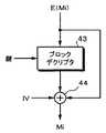
図9は、エンクリプタ9に対応するデクリプタ31(図7参照)の構成例を示す。上述したように、暗号化されたデータE(Mi)がブロックデクリプタ43に供給される。ブロックデクリプタ43に対して鍵が供給され、データE(Mi)が復号される。復号データがmod2の加算器44に供給される。セクタの最初のデータに関しては、加算器44でそのセクタのIVと加算される。2番目以降のデータに関しては、加算器44にてブロックデクリプタ43の出力データと入力データとが加算される。加算器44の出力に復号データMiが得られる。
【0065】
この発明は、上述した一実施形態等に限定されるものでは無く、この発明の要旨を逸脱しない範囲内で様々な変形や応用が可能である。例えば再生装置、受信装置において、復号した後にビットa1を”0” にセットしている。しかしながら、この処理を行なわないで、復号後では、ビットa1を無視するようにしても良い。また、この発明による記録方法を読み出し専用形光ディスクに対して適用する場合では、図6に示す記録装置は、マスタリング装置に対して適用される。さらに、この発明は、光ディスク限らず、他のデータ記録媒体例えばメモリカードに対しても適用することができる。
【0066】
【発明の効果】
この発明では、MPEGシステムと一般アプリケーションのように異なるシステムのデータを融合したデータフォーマットでセクタ単位の暗号化制御を行うことができる。したがって、二つのシステムのそれぞれのデータを識別して処理を切り替える場合の問題を生じない。また、データ構成を融合した結果、1セクタに配することができるデータ量が減少せず、効率が良い利点がある。さらに、融合した結果、各システムで矛盾を生じることがない。
【0067】
この発明では、各システムにおいて、暗号化の初期値をセクタ内の同一の位置に配置することができ、異なるシステムのデータであっても、共通の暗号化および復号化を行うことができる。しかも、スクランブル制御が規定されていないMPEG1システムにおいても、各セクタが暗号化制御の情報を持つことができ、コンテンツのセキュリティ(著作権)を保護することができる。暗号化を復号した後に、ビットの書き換えを行うことによって、復号データがMPEG1システムおよびMPEG2システムで利用できる。さらに、スタッフィングバイトを付加する場合でも、暗号化制御のためのビットの位置が固定であり、可変長に対応することが可能となる。
【図面の簡単な説明】
【図1】この発明を適用できるMPEG2システムのデータ構成を説明する略線図である。
【図2】MPEG2システムのデータ構成の一例を示す略線図である。
【図3】一般的アプリケーションにおけるデータフォーマットとMPEG2システムのデータフォーマットとの融合方法の例を説明するための略線図である。
【図4】この発明の一実施形態におけるデータ構成を説明するための略線図である。
【図5】この発明の一実施形態における暗号化制御ビットの定義の一例および他の例を示す略線図である。
【図6】この発明が適用された記録装置、送信装置の一実施形態のブロック図である。
【図7】この発明が適用された再生装置、受信装置の一実施形態のブロック図である。
【図8】この発明に使用できるエンクリプタの一例のブロック図である。
【図9】この発明に使用できるデクリプタの一例のブロック図である。
【符号の説明】
a1,a2・・・暗号化制御のためのビット、7・・・暗号化判断部、8,10,32・・・ビット設定回路、9・・・エンクリプタ、14,23・・・光ピックアップ、15,21・・・光ディスク、別部、11,13・・・エンクリプタ、30・・・IV読取部、31・・・デクリプタ[0001]
TECHNICAL FIELD OF THE INVENTION
The present invention merges different data formatsData output method, recording method and apparatus, reproduction method and apparatus, data transmission method and reception method About.
[0002]
[Prior art]
In a hard disk drive, a floppy (registered trademark) disk drive, a CD-ROM / CD-R / CD-RW drive or the like as an external storage device of a personal computer, data is processed in sector units. For example, the sector size is 2K bytes (2048 bytes). In order to protect the copyright of the content, the content data is encrypted and recorded. In order to control whether to encrypt or not encrypt in sector units, an encryption control bit is required for each sector. In addition, for a CBC (Chaining Block Ciphering) mode, an IV (Initial)
Vector: the initial value of encryption).
[0003]
MPEG (Moving Picture Experts Group) is known as a format for transmitting or recording multimedia contents. FIG. 1A shows a data structure of a program stream of the MPEG2 system. One program is from the head pack header to the end code. Generally, a pack is composed of a plurality of packets. A system header is added to the first pack. It is optional to add a system header to the second and subsequent packets. A pack header is added to the head of each pack.
[0004]
As shown in FIG. 1A, the pack header indicates a pack start code (32 bits), an identification code (2 bits), an SCR (System Clock Reference: system time reference value) (42 + 4 bits), and a bit rate of this stream. It is composed of a multiplexing rate (22 + 2 bits), a stuffing length (3 + 8 bits), and a stuffing byte (8 × M bits). The stuffing byte is dummy data used to keep the packet data length constant, for example, and has no meaningful information.
[0005]
FIG. 1B shows the structure of a packet. The packet start code (32 bits) located at the head is composed of a head start code (24 bits) and a stream ID (8 bits). Next, a packet length (16 bits) indicating the data length of the packet is located. The 2-bit control code is “01” in the MPEG2 system. The first two bits of the flag and the control (14 bits) are used for PES (Packetized Elementary Stream) scrambling control. The header length is indicated by the PES header length (8 bits). Items conditionally coded corresponding to the flag and the control include PTS (Presentation Time Stamp) (33 + 7 bits), DTS (Decoding Time Stamp) (33 + 7 bits), and other codes. Further, a stuffing byte (8 × M bits) is added, followed by packet data (8 × N bits).
[0006]
FIG. 2 shows that the data configuration in the MPEG2 system is reduced to 2K bytes in order to integrate with a data format in a general application (hereinafter, appropriately referred to as a general data format) having a sector length of 2K bytes (2048 bytes). Indicates a delimited one. As shown in FIG. 2, one pack is composed of one packet. The size of one pack is 2 Kbytes. Therefore, one pack corresponds to one sector of the general format. A pack header (14 bytes) is located at the beginning of one pack, and thereafter, a PES header (14 bytes), a stream header (4 bytes), and user data (2016 bytes) are arranged in this order. When user data is divided in units of 8 bytes, user (or packet) data is composed of data from D1 to D252. The user data is, for example, audio data that has been subjected to compression encoding and encryption. Such a data configuration shown in FIG. 2 satisfies the encoding rule of the MPEG2 system.
[0007]
The pack header is the same as that shown in FIG. 1A, except that the stuffing byte is not added and the pack header has a length of 14 bytes. That is, the pack header is a total of a pack start code (32 bits), a control code (2 bits), an SCR (42 + 4 bits), a multiplexing rate (22 + 2 bits) indicating the bit rate of this stream, and a stuffing length (3 + 8 bits). It is composed of 112 bits (= 14 bytes). The reason why the stuffing byte is not added is to prevent the position of the scramble control bit from being changed by the stuffing byte.
[0008]
The PES header is the same as that shown in FIG. 1B, except that the packet start code (32 bits), the packet length (16 bits), the 2-bit control code, the flag and control (14 bits), the PES header A total of 112 bits (= 14 bytes) up to the length (8 bits) and the PTS (33 + 7 bits) are used.
[0009]
In the stream header (4 bytes), an audio encoding method (linear PCM, MP3 (MPEG1 Audio Layer III), AAC (Advanced Audio Coding), ATRAC3 (Adaptive Transfer Acoustic Coding, 3 bits indicating information, etc.)) 64 Kbps, etc., and information on the number of channels (monaural, stereo, 5.1 channels, etc.).
[0010]
A bit number is added to 32 bytes (= 256 bytes) of the pack header, the PES header, and the stream header in order to define bit positions. Assuming that the leading bit is
[0011]
The 2-bit control code of
[0012]
FIG. 3A shows a data structure of one sector of a general data format (meaning a data format in a general application other than the MPEG system). Assuming that encryption with IV (normally, the processing is often performed in units of 8 bytes) is assumed in the CBC (Chaining Block Ciphering) mode, the first 8 bytes include scramble control, IV, and the like. For example, 4 bytes are used as IV. 2040 bytes excluding the sector header are user data. Therefore, the user data is 2040 bytes, and when divided into 8 byte units, data from D1 to D255 is included.
[0013]
[Problems to be solved by the invention]
It is desirable that both the data format of the MPEG2 system described above and the general data format shown in FIG. 3A can be handled by, for example, a personal computer, an optical disk drive, and application software (hereinafter referred to as a drive or the like). For example, general application data is handled in a general data format, and audio and video data is handled in MPEG2 system data. By setting audio and video data in the data format of the MPEG2 system, audio data and video data can be multiplexed, and for example, lyrics images can be recorded together with audio. Also, by using the PTS, which is a time stamp, high-speed access is possible even when variable-length compression encoding is performed.
[0014]
When two different data formats are used, a method in which a drive or the like identifies the two and switches between them may be considered. This method makes it difficult for a drive or the like to distinguish between the two formats. In addition, in order to determine whether or not encryption is performed in sector units, in the MPEG2 system and the general data format, bits at different positions must be viewed, and it is difficult to determine whether or not encryption is performed in sector units. is there.
[0015]
Another method is to fuse two different data formats. In this case, no problem occurs with the switching. FIG. 3B shows a data structure when the general data format is adapted to the MPEG2 system. In the case of the MPEG2 system, the first 32 bytes are a pack header, a PES header, and a stream header as shown in FIG. 2A. The information (scramble control bits and IV) of the sector header (8 bytes) of the general data format can have 32 bytes. However, in the general data format, an 8-byte header is sufficient, but since 32 bytes are required, there is a problem that (32−8 = 24 bytes) is wasted. In other words, there is a problem that the user data of one sector is reduced from 2040 bytes to 2016 bytes. Further, there is a problem that the stuffing byte cannot be used to fix the position of the scramble control bit in the MPEG2 system.
[0016]
On the other hand, when the MPEG2 system is adjusted to the general data format, as shown in FIG. 3C, an 8-byte header is added to the head of one sector of the data format of the MPEG2 system. As a result, there is no problem in applications other than the MPEG2 system, but there is a problem in the application of the MPEG2 system that the first 8 bytes are wasted.
[0017]
Therefore, an object of the present invention is to avoid the problem that wasteful data is generated and user data is reduced, and it is possible to combine data structures of different systems.Data output method, recording method and apparatus, reproduction method and apparatus, data transmission method and reception method Will be provided.
[0018]
[Means for Solving the Problems]
In order to solve the above-mentioned problem, the invention of
[0019]
The invention of claim 8 isThe input data is converted into data in units of one sector in which a header in which at least one bit of a start code and two bits following the start code is a bit indicating encryption control is added to the head, and the converted data is converted. When encrypting, at least one of the two bits following the start code is set to indicate that the data is encrypted, the converted data is encrypted, and the converted data is recorded in the encrypted data. Recording method for performing encoding processing for recording on a recording medium It is.
[0020]
ClaimFifteen The invention ofA conversion unit for converting the input data into data in units of one sector in which a header in which at least one bit of a start code and two bits following the start code is a bit indicating encryption control is added to the head; And a setting unit for setting at least one of the two bits following the start code to indicate that the data is encrypted, and an output data from the setting unit. An encryption processing unit that performs an encryption process on the data, an encoding processing unit that performs an encoding process for recording the output data from the encryption processing unit, and a recording unit that records the output data from the encoding processing unit on a recording medium. Recording device provided with It is.
[0021]
[0022]
[0023]
[0024]
[0030]
By using two bits at a predetermined position for encryption control, two different systems, for example, an MPEG2 system and a general application can be integrated without causing useless data and without contradiction. Of course, it is possible to perform encryption control on a sector-by-sector basis. Further, even in the MPEG1 system in which the scramble control bit is not specified, the encryption control can be performed, and the security of the MPEG1 content can be protected. Since the initial value of the encryption is located at the same position in each data format, it is possible to perform encryption by the same encryption system. After the encryption has been decrypted, it can be used as an MPEG1 and MPEG2 system. In the MPEG system, the stuffing byte can be used because the encryption control bit is arranged at a fixed position before the stuffing byte.
[0031]
BEST MODE FOR CARRYING OUT THE INVENTION
Hereinafter, an embodiment of the present invention will be described. First, a data format in this embodiment will be described with reference to FIG. FIG. 4A shows an example in which one sector is 2 Kbytes (2048 bytes). However, 2 Kbytes is an example, and one sector may be other than 2 Kbytes. Of the first 8 bytes (
[0032]
FIG. 4B shows a part of the data structure when the present invention is applied to the MPEG2 system. That is, as described with reference to FIG. 2, the first 32 bits correspond to the pack start code, then the control codes (a1 and a2) are arranged, and then the (42 + 2) -bit SCR is arranged. You. Therefore, the control code is also used for scrambling control, and the IV is constituted by 30 bits of the SCR. Data after
[0033]
In the MPEG2 system, a scramble control bit is arranged in bits 162 and 163. As for the scramble control bit, "00" is not scrambled, "01" is scrambled, and "10" and "11" are reserved (undefined). ing. When the control codes (a1 and a2) are used for encryption control as in one embodiment, it is assumed that the information of the control code and the information of the scramble control bit do not conflict.
[0034]
FIG. 4C is an example in which the present invention is applied to a general data format other than MPEG. The first 32 bits are used as a reserved or system header. Next, 2-bit control codes a1 and a2 are arranged, and the remaining 30 bits are random numbers generated by hardware or software. The control code and the random number correspond to IV. However, when a length of 64 bits is required as the IV, data in which 32 bits from
[0035]
FIG. 5 shows an example of the definition of a 2-bit control code (a1 and a2) and another example. In the example shown in FIG. 5A, two bits are used for discrimination between MPEG1 and MPEG2. “A1 a2” = “00” is defined as no encryption in the MPEG1 system, and “a1 a2” = “01” is defined as no encryption in the MPEG2 system. This is consistent with the definition of MPEG. “A1 a2” = “10” is defined as having encryption in the MPEG1 system, and “a1 a2” = “11” is defined as having encryption in the MPEG2 system. When the MPEG1 system is not used, “a1 a2” = “00” and “a1 a2” = “10” may be undefined.
[0036]
Only bit 32 (a1) may be used for encryption control. In this case, “a1a2” = “00” is defined as no encryption in the MPEG1 system, “a1a2” = “01” is defined as no encryption in the MPEG2 system, and “1x” (x is “0”). "Or" 1 "
This indicates that any of these may be used. ) Is defined as encrypted.
[0037]
In another example shown in FIG. 5B, two bits are used for controlling encryption. “A1 a2” = “00” is undefined, “a1 a2” = “01” is defined as no encryption, and “a1 a2” = “10” is defined as encryption by the second encryption method. Then, “a1 a2” = “11” is defined as encryption by the first encryption method different from the second encryption method. In the first and second encryption methods, the encryption key and the encryption method are different. As a method for differentiating the encryption key, a method of hashing the key Ka of the first encryption method to obtain the key Kb of the second encryption method, a method of using a key having no relation to the encryption method, and the like are possible. It is.
[0038]
The reason for making the encryption method different is to make the encryption method different depending on the type of content. For example, the encryption is different between the trial listening content and the original non-trial listening content, for example, the charged content. The key Ka in the above-described example is used to decrypt the chargeable content, and the key Kb is used to decrypt the trial content. The key Ka can be created from the key Ka by a hash operation, but the key Ka cannot be created from the key Kb because the hash function is one-way.
[0039]
Further, in the example of FIG. 5B, when the two bits “a1 a2” mean that encryption is performed, when the encryption is decrypted, the two bits are changed to a value meaning that no encryption is performed. In the MPEG1 system, when decoding is performed, “a1 a2” is rewritten to “00”, and in the MPEG2 system, when decoding is performed, “a1 a2” is rewritten to “01”. Note that two undefined bits may indicate the third encryption method.
[0040]
An embodiment of a recording device and a transmission device to which the present invention is applied will be described with reference to FIG. In FIG. 6, the recording device and the transmission device are depicted as the same figure, but usually both are separately configured as different systems.
[0041]
The input data is time-division multiplexed in the
[0042]
When the MPEG1 system is used, the multiplexed data is supplied to the
[0043]
The
[0044]
The output data of the
[0045]
In the case of performing the encryption, the data output from the
[0046]
The encrypted data of the encryptor 9 or the output data of the
[0047]
In the case of a recording device, a modulation output from the
[0048]
The
[0049]
The group meanders (referred to as a wobble) in the radial direction of the
[0050]
An optical disc having such a wobbled groove is manufactured as follows. The mastering device irradiates the photoresist film coated on the disk-shaped glass master with laser light, and deflects or oscillates the laser light in the radial direction to form a wobbling groove having address information, clock information, and the like. Form. A master disc is created by developing the photoresist film exposed by the irradiation of the laser beam, a stamper is created by electroforming from the master disc, and the above-described wobble groove is formed by performing injection molding using the stamper. Is formed. An optical disk is produced by applying a phase-change type recording material to the disk substrate using a technique such as sputtering.
[0051]
The recording apparatus shown in FIG. 6 is not limited to dedicated hardware, but can be realized by a drive and a personal computer (software). The configuration after the error correction encoding circuit 11 is a hardware configuration (drive such as a current CD-R drive, CD-R / W drive, etc.), and the rest is realized by software. In the recording device, for example, the CD-
[0052]
In the case of the transmission device, the output of the
[0053]
FIG. 7 shows an embodiment of a reproducing apparatus and a receiving apparatus to which the present invention is applied. Like the recording device, the playback device is configured by a drive having a hardware configuration (a CD-ROM drive, a CD-R drive, a CD-RW drive, etc.) and application software. It is also possible to use a hardware configuration.
[0054]
In FIG. 7, an optical disk denoted by
[0055]
In the reproduction
[0056]
In the case of a receiving device, a signal received by the receiving
[0057]
A tracking error signal and a focus error signal are supplied to a servo circuit (not shown), and the rotation of the
[0058]
The data corrected by the
[0059]
The read IV and the encrypted data are supplied to the
[0060]
The
[0061]
The reproduction data determined to be of the general application by the
[0062]
FIG. 8 shows an example of the encryptor 9 (see FIG. 6) in the CBC mode. For example, data Mi divided every 64 bits (8 bytes) is supplied to an adder 41 (for example, an exclusive OR gate) of mod2. In the case of the first data M1 of one sector, IV (initial value) is supplied to the
[0063]
The key (128 bits) is supplied to the
[0064]
FIG. 9 shows a configuration example of a decryptor 31 (see FIG. 7) corresponding to the encryptor 9. As described above, the encrypted data E (Mi) is supplied to the
[0065]
The present invention is not limited to the above-described embodiment and the like, and various modifications and applications are possible without departing from the gist of the present invention. For example, in the reproducing apparatus and the receiving apparatus, the bit a1 is set to "0" after decoding. However, the bit a1 may be ignored after decoding without performing this processing. When the recording method according to the present invention is applied to a read-only optical disk, the recording device shown in FIG. 6 is applied to a mastering device. Further, the present invention can be applied not only to optical discs but also to other data recording media such as memory cards.
[0066]
【The invention's effect】
According to the present invention, it is possible to perform encryption control on a sector-by-sector basis in a data format in which data of different systems such as an MPEG system and a general application are combined. Therefore, there is no problem in switching processing by identifying data of the two systems. In addition, as a result of merging the data structures, there is an advantage that the amount of data that can be allocated to one sector does not decrease and efficiency is high. Further, as a result of the fusion, no inconsistency occurs in each system.
[0067]
According to the present invention, in each system, the initial value of encryption can be arranged at the same position in a sector, and common encryption and decryption can be performed even for data of different systems. In addition, even in an MPEG1 system in which scramble control is not specified, each sector can have encryption control information, and content security (copyright) can be protected. By performing bit rewriting after decrypting the encryption, the decrypted data can be used in the MPEG1 system and the MPEG2 system. Further, even when a stuffing byte is added, the position of the bit for encryption control is fixed, and it is possible to cope with a variable length.
[Brief description of the drawings]
FIG. 1 is a schematic diagram illustrating a data configuration of an MPEG2 system to which the present invention can be applied.
FIG. 2 is a schematic diagram illustrating an example of a data configuration of an MPEG2 system.
FIG. 3 is a schematic diagram for explaining an example of a method of fusing a data format in a general application with a data format of an MPEG2 system.
FIG. 4 is a schematic diagram illustrating a data configuration according to an embodiment of the present invention.
FIG. 5 is a schematic diagram illustrating an example of definitions of encryption control bits and another example according to an embodiment of the present invention;
FIG. 6 is a block diagram of a recording device and a transmission device according to an embodiment of the present invention;
FIG. 7 is a block diagram of an embodiment of a reproducing device and a receiving device to which the present invention is applied.
FIG. 8 is a block diagram of an example of an encryptor that can be used in the present invention.
FIG. 9 is a block diagram showing an example of a decryptor that can be used in the present invention.
[Explanation of symbols]
a1, a2: bits for encryption control, 7: encryption determination unit, 8, 10, 32: bit setting circuit, 9: encryptor, 14, 23: optical pickup, 15, 21 ... optical disk, separate part, 11, 13 ... encryptor, 30 ... IV reading part, 31 ... decryptor
Claims (49)
Translated fromJapanese上記変換されたデータを暗号化する場合には、上記開始コードに続く2ビットのうちの少なくとも1ビットをデータが暗号化されていることを示すように設定し、
上記変換されたデータを暗号化し、
上記暗号化されたデータをエンコードして出力するデータ出力方法。The input data is converted into data in units of one sector in which a header in which at least one bit of a start code and two bits following the start code is a bit indicating encryption control is added to the head,
When encrypting the converted data, at least one bit of the two bits following the start code is set to indicate that the data is encrypted,
Encrypt the converted data,
A data output method for encoding and outputting the encrypted data .
上記変換されたデータを暗号化する場合には、上記開始コードに続く2ビットのうちの少なくとも1ビットをデータが暗号化されていることを示すように設定し、
上記変換されたデータを暗号化し、
上記暗号化されたデータに記録のためのエンコード処理を施して記録媒体に記録する記録方法。The input data is converted into data in units of one sector in which a header in which at least one bit of a start code and two bits following the start code is a bit indicating encryption control is added to the head,
When encrypting the converted data, at least one bit of the two bits following the start code is set to indicate that the data is encrypted,
Encrypt the converted data,
A recording method of performing an encoding process for recording on the encrypted data and recording the encoded data on a recording medium .
上記変換部によって変換されたデータを暗号化する場合には、上記開始コードに続く2ビットのうちの少なくとも1ビットをデータが暗号化されていることを示すように設定する設定部と、
上記設定部からの出力データに暗号化処理を施す暗号化処理部と、
上記暗号化処理部からの出力データに記録のためのエンコード処理を施すエンコード処理部と、
上記エンコード処理部からの出力データを記録媒体に記録する記録部とを備えている記録装置。A conversion unit for converting the input data into data of one sector in which a header in which at least one bit of a start code and two bits following the start code is a bit indicating encryption control is added to the head,
A setting unit configured to set at least one bit of two bits following the start code to indicate that the data is encrypted, when encrypting the data converted by the conversion unit;
An encryption processing unit that performs encryption processing on output data from the setting unit;
An encoding processing unit that performs encoding processing for recording on output data from the encryption processing unit;
A recording unit for recording output data from the encoding processing unit on a recording medium .
上記デコードされたデータの上記開始コードに続く2ビットのうちの少なくとも1ビットを検出し、
上記検出した結果、上記デコードされたデータが暗号化されているときには暗号を解読し、
上記解読されたデータを1セクタ単位のデータから所定のデータ単位のデータに変換し出力する再生方法。The data is read from a recording medium on which data in units of one sector in which a header in which at least one bit of user data, a start code, and two bits following the start code is a bit indicating encryption control is added at the beginning is recorded. Decode the data
Detecting at least one of the two bits following the start code of the decoded data;
As a result of the detection, when the decoded data is encrypted, decrypt the code,
A reproducing method for converting the decrypted data from data of one sector unit to data of a predetermined data unit and outputting the converted data .
上記デコーダからの出力データの上記開始コードに続く2ビットのうちの少なくとも1ビットを検出する検出部と、
上記検出部による検出の結果、上記デコードされたデータが暗号化されているときには上記デコーダからの出力データの暗号を解読する解読部と、
上記解読部からの出力データを1セクタ単位のデータから所定のデータ単位のデータに変換して出力する変換部とを備えている再生装置。The data is read from a recording medium on which data in units of one sector in which a header in which at least one bit of user data, a start code, and two bits following the start code is a bit indicating encryption control is added at the beginning is recorded. A decoder for decoding the data
A detection unit for detecting at least one bit of two bits following the start code of output data from the decoder;
As a result of detection by the detection unit, when the decoded data is encrypted, a decryption unit that decrypts the encryption of output data from the decoder,
A conversion unit for converting output data from the decoding unit from data in units of one sector to data in a predetermined data unit and outputting the converted data ;
上記変換されたデータを暗号化する場合には、上記開始コードに続く2ビットのうちの少なくとも1ビットをデータが暗号化されていることを示すように設定し、
上記変換されたデータを暗号化し、
上記暗号化されたデータに送信のためのエンコード処理を施して送信するデータ送信方法。The input data is converted into data in units of one sector in which a header in which at least one bit of a start code and two bits following the start code is a bit indicating encryption control is added to the head,
When encrypting the converted data, at least one bit of the two bits following the start code is set to indicate that the data is encrypted,
Encrypt the converted data,
A data transmission method in which the encrypted data is subjected to an encoding process for transmission and transmitted .
受信したデータをデコードし、
上記デコードされたデータの上記開始コードに続く2ビットのうちの少なくとも1ビットを検出し、
上記検出した結果、上記デコードされたデータが暗号化されているときには暗号を解読し、
上記解読されたデータを1セクタ単位のデータから所定のデータ単位のデータに変換し出力するデータ受信方法。Receiving data in units of one sector in which a header in which at least one bit of user data, a start code, and two bits following the start code is a bit indicating encryption control is added at the beginning,
Decode the received data,
Detecting at least one of the two bits following the start code of the decoded data;
As a result of the detection, when the decoded data is encrypted, decrypt the code,
A data receiving method for converting the decrypted data from data of one sector unit to data of a predetermined data unit and outputting the converted data .
Priority Applications (7)
| Application Number | Priority Date | Filing Date | Title |
|---|---|---|---|
| JP2001289982AJP3584913B2 (en) | 2001-09-21 | 2001-09-21 | Data output method, recording method and apparatus, reproduction method and apparatus, data transmission method and reception method |
| CNB028031997ACN1305061C (en) | 2001-09-21 | 2002-09-19 | Data output method, recording method and device, reproducing method and device, and data transmitting method and receiving method |
| EP02799482AEP1429329A4 (en) | 2001-09-21 | 2002-09-19 | Data output method, recording method and apparatus, reproduction method and apparatus, data transmission method and reception method |
| KR1020037006685AKR100881928B1 (en) | 2001-09-21 | 2002-09-19 | Data output method, recording method and apparatus, playback method and apparatus, data transmission method and reception method |
| US10/416,385US7657032B2 (en) | 2001-09-21 | 2002-09-19 | Data outputting method, recording method and apparatus, reproducing method and apparatus, and data transmitting method and receiving method |
| PCT/JP2002/009609WO2003028027A1 (en) | 2001-09-21 | 2002-09-19 | Data output method, recording method and apparatus, reproduction method and apparatus, data transmission method and reception method |
| CN2006101567645ACN101017690B (en) | 2001-09-21 | 2002-09-19 | Data output method, recording method, recording apparatus and data sending method |
Applications Claiming Priority (1)
| Application Number | Priority Date | Filing Date | Title |
|---|---|---|---|
| JP2001289982AJP3584913B2 (en) | 2001-09-21 | 2001-09-21 | Data output method, recording method and apparatus, reproduction method and apparatus, data transmission method and reception method |
Related Child Applications (1)
| Application Number | Title | Priority Date | Filing Date |
|---|---|---|---|
| JP2004175170ADivisionJP4551700B2 (en) | 2004-06-14 | 2004-06-14 | Recording method, recording apparatus, reproducing method, reproducing apparatus, and recording medium |
Publications (2)
| Publication Number | Publication Date |
|---|---|
| JP2003100019A JP2003100019A (en) | 2003-04-04 |
| JP3584913B2true JP3584913B2 (en) | 2004-11-04 |
Family
ID=19112390
Family Applications (1)
| Application Number | Title | Priority Date | Filing Date |
|---|---|---|---|
| JP2001289982AExpired - Fee RelatedJP3584913B2 (en) | 2001-09-21 | 2001-09-21 | Data output method, recording method and apparatus, reproduction method and apparatus, data transmission method and reception method |
Country Status (6)
| Country | Link |
|---|---|
| US (1) | US7657032B2 (en) |
| EP (1) | EP1429329A4 (en) |
| JP (1) | JP3584913B2 (en) |
| KR (1) | KR100881928B1 (en) |
| CN (2) | CN1305061C (en) |
| WO (1) | WO2003028027A1 (en) |
Families Citing this family (19)
| Publication number | Priority date | Publication date | Assignee | Title |
|---|---|---|---|---|
| JP4543623B2 (en)* | 2003-05-19 | 2010-09-15 | 日本電気株式会社 | Encrypted communication method in communication system |
| US7283455B2 (en)* | 2003-07-31 | 2007-10-16 | Hewlett-Packard Development Company, L.P. | Data media having variable control field in data units |
| EP1654732B1 (en)* | 2003-08-01 | 2014-05-21 | Koninklijke Philips N.V. | Record carrier comprising encryption indication information |
| CA2544605C (en)* | 2003-11-14 | 2013-07-02 | Sonic Solutions | Secure transfer of content to writable media |
| US20070276756A1 (en)* | 2004-08-06 | 2007-11-29 | Kyoichi Terao | Recording/Reproducing Device, Recording Medium Processing Device, Reproducing Device, Recording Medium, Contents Recording/Reproducing System, And Contents Recording/Reproducing Method |
| CN101031968A (en)* | 2004-09-28 | 2007-09-05 | 皇家飞利浦电子股份有限公司 | Method and device for storing data on a record medium and for transferring information |
| KR100589541B1 (en)* | 2004-11-25 | 2006-06-14 | 소프트캠프(주) | Secure transmission system of data through online between virtual disks whose access is controlled and secure transmission method through it |
| US7940930B2 (en)* | 2005-05-02 | 2011-05-10 | Nds Limited | Native scrambling system |
| KR100846787B1 (en) | 2006-02-15 | 2008-07-16 | 삼성전자주식회사 | Method and apparatus for importing transport stream |
| WO2008079112A1 (en)* | 2006-12-20 | 2008-07-03 | Thomson Licensing | Embedded audio routing switcher |
| US10776489B2 (en) | 2007-03-06 | 2020-09-15 | Unisys Corporation | Methods and systems for providing and controlling cryptographic secure communications terminal operable to provide a plurality of desktop environments |
| US9270457B2 (en) | 2008-12-31 | 2016-02-23 | Intel Corporation | Optimizing security bits in a media access control (MAC) header |
| CN101860737B (en)* | 2009-04-10 | 2012-05-30 | 杭州海康威视数字技术股份有限公司 | Packaging method and device of MPEG2 system layer for reducing transmission time delay |
| JP2011151689A (en)* | 2010-01-22 | 2011-08-04 | Fujitsu Ltd | Information processing apparatus and information processing method |
| US11030305B2 (en) | 2010-10-04 | 2021-06-08 | Unisys Corporation | Virtual relay device for providing a secure connection to a remote device |
| US8725788B2 (en) | 2011-05-27 | 2014-05-13 | Adobe Systems Incorporated | System and method for decryption of content including partial-block discard |
| US8687809B2 (en)* | 2011-05-27 | 2014-04-01 | Adobe Systems Incorporated | System and method for decryption of content including disconnected encryption chains |
| US9088805B2 (en)* | 2012-02-08 | 2015-07-21 | Vixs Systems, Inc. | Encrypted memory device and methods for use therewith |
| US9819601B2 (en) | 2012-12-27 | 2017-11-14 | Vonage America Inc. | Systems and methods of modifying data packets used in IP telephony communications |
Family Cites Families (20)
| Publication number | Priority date | Publication date | Assignee | Title |
|---|---|---|---|---|
| JPH0856356A (en)* | 1994-08-10 | 1996-02-27 | Fujitsu Ltd | Encoding device and decoding device |
| JP3739456B2 (en) | 1994-12-29 | 2006-01-25 | 富士通株式会社 | Data reproduction system, replaceable recording medium, and data reproduction method |
| US5602920A (en)* | 1995-05-31 | 1997-02-11 | Zenith Electronics Corporation | Combined DCAM and transport demultiplexer |
| JP3484832B2 (en)* | 1995-08-02 | 2004-01-06 | ソニー株式会社 | Recording apparatus, recording method, reproducing apparatus and reproducing method |
| US5684876A (en)* | 1995-11-15 | 1997-11-04 | Scientific-Atlanta, Inc. | Apparatus and method for cipher stealing when encrypting MPEG transport packets |
| JPH09162859A (en)* | 1995-12-07 | 1997-06-20 | Fujitsu Ltd | Scramble method and apparatus, descramble method and apparatus, and data transmission method and system |
| JP3206468B2 (en)* | 1996-12-25 | 2001-09-10 | 日本ビクター株式会社 | Digital signal recording method |
| JPH11176091A (en)* | 1997-12-15 | 1999-07-02 | Hitachi Ltd | Digital information input / output device, receiving device, recording device, and reproducing device |
| JP3835655B2 (en)* | 1998-06-09 | 2006-10-18 | ソニー株式会社 | Information signal reproducing apparatus, information signal processing apparatus, information signal reproducing method and information signal output method |
| JP2000231758A (en) | 1999-02-10 | 2000-08-22 | Toshiba Corp | Data storage device, method for recording encrypted data, and recording medium |
| CN1143292C (en)* | 1999-02-26 | 2004-03-24 | 日本胜利株式会社 | Information recording method, recording apparatus, recording/reproducing method, and recording medium |
| US6865747B1 (en)* | 1999-04-01 | 2005-03-08 | Digital Video Express, L.P. | High definition media storage structure and playback mechanism |
| JP2000293936A (en)* | 1999-04-08 | 2000-10-20 | Hitachi Ltd | Digital signal recording device, reproducing device, and recording medium |
| JP2001016196A (en) | 1999-04-28 | 2001-01-19 | Fuji Soft Abc Inc | Encryption / decryption method using multiple affine keys, authentication method, and devices using the same |
| JP2000322825A (en)* | 1999-05-13 | 2000-11-24 | Hitachi Ltd | Digital signal recording device |
| JP2001075474A (en) | 1999-08-25 | 2001-03-23 | Shijin Kogyo Sakushinkai | Devices and methods of escrow encryption without key exchange |
| EP1089273A3 (en)* | 1999-09-30 | 2002-08-28 | Matsushita Electric Industrial Co., Ltd. | Information recording medium for recording a scrambled part of content information, and method and apparatus for reproducing information recorded therein |
| JP2001186521A (en)* | 1999-12-22 | 2001-07-06 | Nec Corp | Image decoder and method therefor |
| JP4303408B2 (en) | 2000-07-18 | 2009-07-29 | ネッツエスアイ東洋株式会社 | Method for recording information with block encryption and recording medium supporting the same |
| EP1223696A3 (en)* | 2001-01-12 | 2003-12-17 | Matsushita Electric Industrial Co., Ltd. | System for transmitting digital audio data according to the MOST method |
- 2001
- 2001-09-21JPJP2001289982Apatent/JP3584913B2/ennot_activeExpired - Fee Related
- 2002
- 2002-09-19KRKR1020037006685Apatent/KR100881928B1/ennot_activeExpired - Fee Related
- 2002-09-19CNCNB028031997Apatent/CN1305061C/ennot_activeExpired - Fee Related
- 2002-09-19WOPCT/JP2002/009609patent/WO2003028027A1/enactiveApplication Filing
- 2002-09-19USUS10/416,385patent/US7657032B2/ennot_activeExpired - Fee Related
- 2002-09-19EPEP02799482Apatent/EP1429329A4/ennot_activeWithdrawn
- 2002-09-19CNCN2006101567645Apatent/CN101017690B/ennot_activeExpired - Fee Related
Also Published As
| Publication number | Publication date |
|---|---|
| EP1429329A1 (en) | 2004-06-16 |
| WO2003028027A1 (en) | 2003-04-03 |
| KR20040034572A (en) | 2004-04-28 |
| EP1429329A4 (en) | 2010-09-01 |
| US20040028231A1 (en) | 2004-02-12 |
| JP2003100019A (en) | 2003-04-04 |
| CN101017690B (en) | 2011-01-26 |
| US7657032B2 (en) | 2010-02-02 |
| CN101017690A (en) | 2007-08-15 |
| CN1476607A (en) | 2004-02-18 |
| CN1305061C (en) | 2007-03-14 |
| KR100881928B1 (en) | 2009-02-04 |
Similar Documents
| Publication | Publication Date | Title |
|---|---|---|
| JP3584913B2 (en) | Data output method, recording method and apparatus, reproduction method and apparatus, data transmission method and reception method | |
| CN100508447C (en) | Encryption device and method, decryption device and method | |
| US7574003B2 (en) | Recording medium, apparatus for forming the recording medium, and apparatus and method for reproducing the recording medium | |
| US7095853B2 (en) | System and method for preventing an illegal copy of contents | |
| KR101219618B1 (en) | Information processing device, information recording medium, contents management system, data processing method, and computer readable recording medium recording a program | |
| EP1148489B1 (en) | Recording medium for storing encrypted audio data, apparatus and method of recording the same, and apparatus and method of reproducing the same | |
| TW530297B (en) | Information recording medium for recording a scrambled part of content information, and method and apparatus for reproducing information recorded therein | |
| US20040213408A1 (en) | Method for managing copy protection information of recording medium | |
| JP4114605B2 (en) | Information processing apparatus, information recording medium, information processing method, and computer program | |
| US20050244001A1 (en) | Information recording medium drive device | |
| JP2003037589A (en) | Device and method for data recording, and device and method for data reproducing | |
| TWI359409B (en) | High-density optical disc, method for recording an | |
| JP2002367282A (en) | Data recording device and method, data recording medium, data reproducing device and method, data transmitting device and method, and data receiving device and method | |
| JP4551700B2 (en) | Recording method, recording apparatus, reproducing method, reproducing apparatus, and recording medium | |
| US20040213113A1 (en) | Method for managing copy protection information of recording medium | |
| EP0940810A1 (en) | Recording medium with copyright protection features | |
| JP2006173853A (en) | Information processing apparatus, information recording medium and information processing method, and computer program | |
| EP1597730A1 (en) | Recording medium, apparatus for forming the recording medium, and apparatus and method for reproducing the recording medium |
Legal Events
| Date | Code | Title | Description |
|---|---|---|---|
| A131 | Notification of reasons for refusal | Free format text:JAPANESE INTERMEDIATE CODE: A131 Effective date:20040413 | |
| TRDD | Decision of grant or rejection written | ||
| A01 | Written decision to grant a patent or to grant a registration (utility model) | Free format text:JAPANESE INTERMEDIATE CODE: A01 Effective date:20040713 | |
| A61 | First payment of annual fees (during grant procedure) | Free format text:JAPANESE INTERMEDIATE CODE: A61 Effective date:20040726 | |
| FPAY | Renewal fee payment (event date is renewal date of database) | Free format text:PAYMENT UNTIL: 20080813 Year of fee payment:4 | |
| FPAY | Renewal fee payment (event date is renewal date of database) | Free format text:PAYMENT UNTIL: 20090813 Year of fee payment:5 | |
| FPAY | Renewal fee payment (event date is renewal date of database) | Free format text:PAYMENT UNTIL: 20100813 Year of fee payment:6 | |
| FPAY | Renewal fee payment (event date is renewal date of database) | Free format text:PAYMENT UNTIL: 20110813 Year of fee payment:7 | |
| FPAY | Renewal fee payment (event date is renewal date of database) | Free format text:PAYMENT UNTIL: 20120813 Year of fee payment:8 | |
| FPAY | Renewal fee payment (event date is renewal date of database) | Free format text:PAYMENT UNTIL: 20120813 Year of fee payment:8 | |
| FPAY | Renewal fee payment (event date is renewal date of database) | Free format text:PAYMENT UNTIL: 20130813 Year of fee payment:9 | |
| LAPS | Cancellation because of no payment of annual fees |