JP3582467B2 - Turbo blood pump - Google Patents
Turbo blood pumpDownload PDFInfo
- Publication number
- JP3582467B2 JP3582467B2JP2000279994AJP2000279994AJP3582467B2JP 3582467 B2JP3582467 B2JP 3582467B2JP 2000279994 AJP2000279994 AJP 2000279994AJP 2000279994 AJP2000279994 AJP 2000279994AJP 3582467 B2JP3582467 B2JP 3582467B2
- Authority
- JP
- Japan
- Prior art keywords
- impeller
- bearing
- upper bearing
- magnet
- pump chamber
- Prior art date
- Legal status (The legal status is an assumption and is not a legal conclusion. Google has not performed a legal analysis and makes no representation as to the accuracy of the status listed.)
- Expired - Fee Related
Links
- 239000008280bloodSubstances0.000titleclaimsdescription36
- 210000004369bloodAnatomy0.000titleclaimsdescription36
- 230000008878couplingEffects0.000claimsdescription25
- 238000010168coupling processMethods0.000claimsdescription25
- 238000005859coupling reactionMethods0.000claimsdescription25
- 230000017531blood circulationEffects0.000claimsdescription15
- 230000005540biological transmissionEffects0.000claimsdescription4
- 230000002093peripheral effectEffects0.000description8
- 208000007536ThrombosisDiseases0.000description5
- 230000015572biosynthetic processEffects0.000description5
- 230000014759maintenance of locationEffects0.000description4
- 230000000694effectsEffects0.000description3
- 206010018910HaemolysisDiseases0.000description1
- 230000008588hemolysisEffects0.000description1
- 230000001771impaired effectEffects0.000description1
- 239000000463materialSubstances0.000description1
Images


Classifications
- F—MECHANICAL ENGINEERING; LIGHTING; HEATING; WEAPONS; BLASTING
- F04—POSITIVE - DISPLACEMENT MACHINES FOR LIQUIDS; PUMPS FOR LIQUIDS OR ELASTIC FLUIDS
- F04D—NON-POSITIVE-DISPLACEMENT PUMPS
- F04D29/00—Details, component parts, or accessories
- F04D29/04—Shafts or bearings, or assemblies thereof
- F04D29/046—Bearings
- F04D29/0467—Spherical bearings
- A—HUMAN NECESSITIES
- A61—MEDICAL OR VETERINARY SCIENCE; HYGIENE
- A61M—DEVICES FOR INTRODUCING MEDIA INTO, OR ONTO, THE BODY; DEVICES FOR TRANSDUCING BODY MEDIA OR FOR TAKING MEDIA FROM THE BODY; DEVICES FOR PRODUCING OR ENDING SLEEP OR STUPOR
- A61M60/00—Blood pumps; Devices for mechanical circulatory actuation; Balloon pumps for circulatory assistance
- A61M60/10—Location thereof with respect to the patient's body
- A61M60/104—Extracorporeal pumps, i.e. the blood being pumped outside the patient's body
- A61M60/109—Extracorporeal pumps, i.e. the blood being pumped outside the patient's body incorporated within extracorporeal blood circuits or systems
- A—HUMAN NECESSITIES
- A61—MEDICAL OR VETERINARY SCIENCE; HYGIENE
- A61M—DEVICES FOR INTRODUCING MEDIA INTO, OR ONTO, THE BODY; DEVICES FOR TRANSDUCING BODY MEDIA OR FOR TAKING MEDIA FROM THE BODY; DEVICES FOR PRODUCING OR ENDING SLEEP OR STUPOR
- A61M60/00—Blood pumps; Devices for mechanical circulatory actuation; Balloon pumps for circulatory assistance
- A61M60/20—Type thereof
- A61M60/205—Non-positive displacement blood pumps
- A61M60/216—Non-positive displacement blood pumps including a rotating member acting on the blood, e.g. impeller
- A61M60/226—Non-positive displacement blood pumps including a rotating member acting on the blood, e.g. impeller the blood flow through the rotating member having mainly radial components
- A61M60/232—Centrifugal pumps
- A—HUMAN NECESSITIES
- A61—MEDICAL OR VETERINARY SCIENCE; HYGIENE
- A61M—DEVICES FOR INTRODUCING MEDIA INTO, OR ONTO, THE BODY; DEVICES FOR TRANSDUCING BODY MEDIA OR FOR TAKING MEDIA FROM THE BODY; DEVICES FOR PRODUCING OR ENDING SLEEP OR STUPOR
- A61M60/00—Blood pumps; Devices for mechanical circulatory actuation; Balloon pumps for circulatory assistance
- A61M60/40—Details relating to driving
- A61M60/403—Details relating to driving for non-positive displacement blood pumps
- A61M60/419—Details relating to driving for non-positive displacement blood pumps the force acting on the blood contacting member being permanent magnetic, e.g. from a rotating magnetic coupling between driving and driven magnets
- A—HUMAN NECESSITIES
- A61—MEDICAL OR VETERINARY SCIENCE; HYGIENE
- A61M—DEVICES FOR INTRODUCING MEDIA INTO, OR ONTO, THE BODY; DEVICES FOR TRANSDUCING BODY MEDIA OR FOR TAKING MEDIA FROM THE BODY; DEVICES FOR PRODUCING OR ENDING SLEEP OR STUPOR
- A61M60/00—Blood pumps; Devices for mechanical circulatory actuation; Balloon pumps for circulatory assistance
- A61M60/40—Details relating to driving
- A61M60/403—Details relating to driving for non-positive displacement blood pumps
- A61M60/422—Details relating to driving for non-positive displacement blood pumps the force acting on the blood contacting member being electromagnetic, e.g. using canned motor pumps
- A—HUMAN NECESSITIES
- A61—MEDICAL OR VETERINARY SCIENCE; HYGIENE
- A61M—DEVICES FOR INTRODUCING MEDIA INTO, OR ONTO, THE BODY; DEVICES FOR TRANSDUCING BODY MEDIA OR FOR TAKING MEDIA FROM THE BODY; DEVICES FOR PRODUCING OR ENDING SLEEP OR STUPOR
- A61M60/00—Blood pumps; Devices for mechanical circulatory actuation; Balloon pumps for circulatory assistance
- A61M60/80—Constructional details other than related to driving
- A61M60/802—Constructional details other than related to driving of non-positive displacement blood pumps
- A61M60/818—Bearings
- A61M60/82—Magnetic bearings
- A—HUMAN NECESSITIES
- A61—MEDICAL OR VETERINARY SCIENCE; HYGIENE
- A61M—DEVICES FOR INTRODUCING MEDIA INTO, OR ONTO, THE BODY; DEVICES FOR TRANSDUCING BODY MEDIA OR FOR TAKING MEDIA FROM THE BODY; DEVICES FOR PRODUCING OR ENDING SLEEP OR STUPOR
- A61M60/00—Blood pumps; Devices for mechanical circulatory actuation; Balloon pumps for circulatory assistance
- A61M60/80—Constructional details other than related to driving
- A61M60/802—Constructional details other than related to driving of non-positive displacement blood pumps
- A61M60/818—Bearings
- A61M60/825—Contact bearings, e.g. ball-and-cup or pivot bearings
- F—MECHANICAL ENGINEERING; LIGHTING; HEATING; WEAPONS; BLASTING
- F04—POSITIVE - DISPLACEMENT MACHINES FOR LIQUIDS; PUMPS FOR LIQUIDS OR ELASTIC FLUIDS
- F04D—NON-POSITIVE-DISPLACEMENT PUMPS
- F04D13/00—Pumping installations or systems
- F04D13/02—Units comprising pumps and their driving means
- F04D13/021—Units comprising pumps and their driving means containing a coupling
- F04D13/024—Units comprising pumps and their driving means containing a coupling a magnetic coupling
- F04D13/026—Details of the bearings
- F—MECHANICAL ENGINEERING; LIGHTING; HEATING; WEAPONS; BLASTING
- F04—POSITIVE - DISPLACEMENT MACHINES FOR LIQUIDS; PUMPS FOR LIQUIDS OR ELASTIC FLUIDS
- F04D—NON-POSITIVE-DISPLACEMENT PUMPS
- F04D13/00—Pumping installations or systems
- F04D13/02—Units comprising pumps and their driving means
- F04D13/021—Units comprising pumps and their driving means containing a coupling
- F04D13/024—Units comprising pumps and their driving means containing a coupling a magnetic coupling
- F04D13/027—Details of the magnetic circuit
Landscapes
- Engineering & Computer Science (AREA)
- Health & Medical Sciences (AREA)
- Heart & Thoracic Surgery (AREA)
- Mechanical Engineering (AREA)
- Hematology (AREA)
- Cardiology (AREA)
- Anesthesiology (AREA)
- Biomedical Technology (AREA)
- Life Sciences & Earth Sciences (AREA)
- Animal Behavior & Ethology (AREA)
- General Health & Medical Sciences (AREA)
- Public Health (AREA)
- Veterinary Medicine (AREA)
- General Engineering & Computer Science (AREA)
- Structures Of Non-Positive Displacement Pumps (AREA)
- External Artificial Organs (AREA)
- Details Of Reciprocating Pumps (AREA)
Description
Translated fromJapanese【0001】
【発明の属する技術分野】
本発明は、血液を搬送するための血液ポンプ、特に、インぺラの回転によって血液に遠心力を与えて流動させるターボ式の血液ポンプに関する。
【0002】
【従来の技術】
血液ポンプは、人工心肺装置等における体外血液循環を行うために不可欠である。血液ポンプとしては、ターボ式のポンプが主流を占めている。ターボ式ポンプは以下のような構造を持つ。すなわち、内部にポンプ室が形成されたハウジングは、その中央部分に血液導入用の入口ポートを有し、ハウジング外周部に血液吐出用の出口ポートを有する。ポンプ室にはインペラが配置され、インペラの回転により血液を流動させる。
【0003】
一例として、本発明者らが開発中のターボ式血液ポンプを図5に示す。図5において、21はハウジングであり、入口ポート21a及び出口ポート(図示せず)を有する。ハウジング21内部にはポンプ室22が形成され、インペラ23が配置されている。インペラ23は、上部軸受け24および下部軸受け25により回転自在に支持されている。ハウジング21の下部中央に設けられた凹部21bには、ロータ26が配置されている。ロータ26は、図示しないが、モータと連結されて回転駆動される。インペラ23の下部には、ハウジング21の凹部21bの側壁の内部側に位置するように従動磁石27が取り付けられている。ロータ26には、凹部21bの側壁の外部側に位置するように駆動磁石28が取り付けられている。従って、従動磁石27と駆動磁石28の間に作用する径方向の磁気吸引力により、ロータ26の回転がインペラ23に伝達される。インペラ23の回転によりポンプ室22内の血液は流動して出口ポートから吐出される。それに伴い、入口ポート21aから血液が導入され、血液の流れが形成される。
【0004】
【発明が解決しようとする課題】
血液ポンプに要求される仕様の1つとして、血栓形成を引き起こさないことが挙げられる。血液ポンプ内の流路に流れの障害となる構造材が存在すると、血液滞留を生じて血栓形成を起こしやすくなる。図5に示した血液ポンプにおいては、上部軸受け24が入口ポート21a内に配置されている。上部軸受け24は、流路としては比較的狭い入口ポート21a内にあって、血流に対して大きな障害となる。特に、軸受け部分の強度を大きくするために太い支柱29を設置すると、血流に対する障害の程度は極めて大きなものになる。
【0005】
上記ような問題を解消するために、特開平10−33664号公報には、インペラにおけるベーンが取り付けられた軸部を中空とし、その中空部を流路とする構造の一例が記載されている。中空の軸部はその外周において、磁気軸受けにより支持されている。この構造によれば、中空部には血流の障害となる部分をなくすことができる。しかしながら、中空の軸部は、直径、長さともにある程度の寸法の大きさが必要であり、装置の小型化を阻む原因となり、また構造も複雑である。例えば小児用の血液ポンプの場合、入口ポートは直径6mm程度であり、この場合、特開平10−33664号公報に記載の構造は採用困難である。
【0006】
一方、インペラの下部に配置した軸受けのみによりインペラを支持する構造を用い、上部の軸受けを不要とすることにより、上記の問題を解消することも考えられる。しかしながら、下部の軸受けのみではインペラの回転が不安定となり易い。特に、モータの回転を磁気結合によりインペラに伝達する構造においては、上下2箇所の軸受けによりインペラを支持することが、安定性の面で望ましい。
【0007】
本発明は、インペラを上下の軸受けにより支持する際の、上部の軸受けによる血流の妨げを軽減し、血液滞留、血栓形成の問題を生ずるおそれの少ないターボ式血液ポンプを提供することを目的とする。
【0008】
【課題を解決するための手段】
本発明は、ポンプ室、入口ポートおよび出口ポートを有するハウジングと、ポンプ室に回転可能に配置されたインペラと、インペラを回転可能に支持する上部及び下部軸受けと、インペラを回転駆動するための駆動力伝達手段とを備えたターボ式血液ポンプを前提とする。上記課題を解決するために、上部軸受けは、入口ポート下方のポンプ室内に位置するように支持され、上部軸受けの上端部を含みインペラの軸に直交する面におけるポンプ室の断面積は、ポンプ室との結合部における入口ポートの流路断面積に対して十分な大きさを有して、上部軸受けによる血流に対する障害が実用上無視できる程度となるように構成される。そのために、入口ポートの下端部に複数本の軸受け支柱の一端が固定され、その軸受け支柱はポンプ室に向かって延びており、その先端に上部軸受けが支持される。インペラの軸は上端に小径部を有し、上部軸受けは下端に軸受孔を有し、小径部が軸受孔に挿入されて軸の上部が上部軸受けにより支持されかつ位置決めされる。インペラの軸の小径部と大径部との境界部にテーパ部が形成され、上部軸受けの端面における軸受孔の周囲は、インペラの軸のテーパ部に対応する形状を有し、インペラの軸のテーパ部は、上部軸受けの端面における軸受孔の周囲に対向している。
【0009】
この構成によれば、上部軸受けによる血流に対する障害は問題にならず、血液滞留、血栓形成の問題を生ずるおそれの少ないターボ式血液ポンプが実現される。
【0012】
また上記構成は、駆動力伝達手段が、ハウジングの外側に配置されモータにより回転駆動されるロータに設けられた駆動磁石と、インペラに設けられた従動磁石とを有し、従動磁石と駆動磁石をハウジングの壁を挟んで対向させることにより磁気結合を形成し、磁気結合によりロータの回転をインペラに伝達するように構成されたターボ式血流ポンプにおいて効果的である。
【0013】
その場合、従動磁石および駆動磁石間に作用する吸引力に基づく磁気結合の方向が、インペラの回転軸に対して傾斜するように従動磁石および駆動磁石が配置された構成とすることができる。
【0014】
【発明の実施の形態】
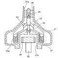
図1は、本発明の一実施の形態におけるターボ式血液ポンプを示す断面図である。1はハウジングであり、血液を通過させ流動させるためのポンプ室2を有する。ハウジング1には、ポンプ室2の上部に連通する入口ポート3と、ポンプ室2の側部に連通する出口ポート4が設けられている。ポンプ室2内にはインペラ5が配置されている。インペラ5は、6枚のベーン6、回転軸7、及びリング状の環状連結部8を有する。ベーン6の中心部側は回転軸7に結合され、周縁部側は環状連結部8に結合されている。回転軸7は、ハウジング1に設けた上部軸受け9及び下部軸受け10により、回転自在に支持されている。環状連結部8には、磁石ケース11が設けられ、磁石ケース11には従動磁石12が埋設、固定されている。従動磁石12は、円柱状であり、環状連結部8の周方向に6個、一定間隔をもって配置されている。
【0015】
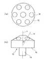
ハウジング1の下部には、ロータ13が配置されている。ロータ13は、互いに結合された駆動軸14と略円柱状の磁気結合部15を有する。駆動軸14は、図示しないが、回転自在に支持されるとともに、モータ等の回転駆動源に連結されて回転駆動される。また、ロータ13とハウジング1とは、図示しないが、相互の位置関係が一定に保持されている。磁気結合部15の上面部には駆動磁石16が埋設、固定されている。図2(a)のロータ13の平面図に示されるように、駆動磁石16は円柱状であり、周方向に6個、一定間隔をもって配置されている。
【0016】
駆動磁石16は、ハウジング1の壁を挟んで従動磁石12と対向する位置関係となるように配置されている。従って、ロータ13とインペラ5との間は、磁気的に連結された状態が形成されている。ロータ13を回転させることにより、インペラ5が磁気結合を介して回転駆動される。
【0017】
上部軸受け9は、入口ポート3の下方であって、ポンプ室2に入り込んだ位置に配置されている。図3に、上部軸受け9の部分を拡大した平面図を示す。同図に示すように、3本の軸受け支柱17が用いられ、各々径方向に延びて流路断面の中心部において上部軸受け9を支持している。図1に示されるように、入口ポート3の下端部内面に固定された軸受け支柱17は、斜め下方に延びてポンプ室2内に入り込み、その先端に上部軸受け9が支持されている。このようにして上部軸受け9が支持された位置では、流路の断面積が、入口ポート3の流路断面積に比べて十分に大きい。ここで入口ポート3の流路断面積とは、図4に示す断面A−A、すなわち入口ポート3とポンプ室2の結合部における断面積SAである。また、上部軸受け9が支持された位置の流路断面積は、図4に示す断面B−B、すなわち、上部軸受け9の上端部の位置でのポンプ室2の断面積SBである。なお、ここでいう流路断面積とは、上部軸受け9および軸受け支柱17が配置されていない状態での面積である。
【0018】
上記の構成により、上部軸受け9の血流に対する障害の程度は、実用上問題のない程度まで軽減される。すなわち、入口ポート3における血流は、軸受け支柱17による妨げは受けるが、上部軸受け9が入口ポート3の内部に位置する場合に比べれば問題にならない。また、ポンプ室2における血流が上部軸受け9により受ける妨げは、流路断面積が拡大された箇所であるため、問題にならない。要するに、上部軸受け9が配置される流路断面積が十分に大きい位置とは、血流に対する障害が実用上問題のない程度に軽減される範囲で、入口ポート3の流路断面積に比べて十分大きいことを意味する。
【0019】
上部軸受け9を支持する位置を決めるための条件として、断面積SAに対する断面積SBの大きさについて検討したところ、断面積SBが
2.32×SA≦SB≦7.50×SA
の範囲であれば、実用的に好適であることが判った。すなわち、断面積SBがこの条件を満たす範囲に上部軸受け9を支持する位置を決めればよい。下限値を外れる場合は血流に障害が及ぶ。また上限値を外れる位置に設定すると、上部軸受け9と下部軸受け10が近接しすぎてインペラ5を適切に支持することが困難になる。なお、断面積SBの上記範囲は、上部軸受け9および軸受け支柱17の寸法により影響を受ける。しかしながら、それらの寸法の実用的な範囲においては、上記の範囲は変更を要することなく、実用的な効果を確保できる。
【0020】
図1に示されるように、従動磁石12が設置された環状連結部8の面は、回転軸7に対して直交せず、所定の角度を有する傾斜面である。同様に駆動磁石16が設置された磁気結合部15の上面も傾斜面である。このように、従動磁石12と駆動磁石16とは、インペラ5の回転軸に対して傾斜した面において、磁気結合を形成している。
【0021】
このように、磁気結合を形成する面を傾斜させることにより、インペラ5とロータ13の間に作用する磁気吸引力は、インペラ5の回転軸に対して傾斜した方向に発生する。その結果、下部軸受け10に対する下向きの負荷が軽減される。従って、下部軸受け10の摩耗が緩和され、磁気結合の強さを十分な大きさにすることができる。
【0022】
しかも、従動磁石12と駆動磁石16が配置される面が斜面であることにより、図3に示した径方向に磁気吸引力を作用させる構成に比べて、環状連結部8の外周面の軸方向寸法を大きくすることなく、対向面積を容易に大きくとることが可能となる。従って、大きな周速度で血液と接触する最外周部の表面積が小さくなり、溶血のおそれが軽減される。また、環状連結部8の内周面とハウジング1の内側に形成される血液滞留部も小さくなり、血栓の形成も緩和される。
【0023】
磁気結合の方向は、図2(b)において、磁気結合部15の上部傾斜面に直交する直線Mにより示される。直線Yは回転軸である。磁気結合の方向Mが回転軸Yに対してなす角αは、30°±15°の範囲に設定される。この範囲であれば、上記の効果をバランスのとれた状態で得ることができる。この範囲より大きいと、径方向の磁気結合における問題、すなわち、周速の大きい外周部分の表面積の増大を招き、好ましくない。またこの範囲より小さいと、上下方向の磁気結合における問題、すなわち、下部軸受け10の負荷の増大を招き、好ましくない。
【0024】
傾斜面は、ロータ13の磁気結合部15が上方に凸となった形状で構成することが好ましい。逆の形状に比べて、インペラ5との間に形成される空間を小さくすることができ、ポンプの小型化に有効だからである。
【0025】
【発明の効果】
本発明によれば、上部軸受けは、入口ポートの流路断面積に比べて流路の断面積が十分に大きい位置に配置されているので、上部軸受けが血流を妨げる程度は、実用上問題のない程度まで軽減される。
【図面の簡単な説明】
【図1】本発明の実施の形態におけるターボ式血液ポンプの断面図
【図2】図1のターボ式血液ポンプのロータを示し、(a)は平面図、(b)は正面図
【図3】図1のターボ式血液ポンプにおける上部軸受けの部分を拡大して示した平面図
【図4】図1のターボ式血液ポンプにおける上部軸受けを支持する位置の設定について説明するための図
【図5】従来例のターボ式血液ポンプの断面図
【符号の説明】
1 ハウジング
2 ポンプ室
3 入口ポート
4 出口ポート
5 インペラ
6 ベーン
7 回転軸
8 環状連結部
9 上部軸受け
10 下部軸受け
11 磁石ケース
12 従動磁石
13 ロータ
14 駆動軸
15 磁気結合部
16 駆動磁石
17 軸受け支柱
21 ハウジング
21a 入口ポート
21b 凹部
22 ポンプ室
23 インペラ
24 上部軸受け
25 下部軸受け
26 ロータ
27 従動磁石
28 駆動磁石
29 支柱[0001]
BACKGROUND OF THE INVENTION
The present invention relates to a blood pump for transporting blood, and more particularly, to a turbo blood pump for causing blood to flow by applying centrifugal force by rotation of an impeller.
[0002]
[Prior art]
A blood pump is indispensable for extracorporeal blood circulation in an oxygenator or the like. As a blood pump, a turbo type pump dominates. The turbo pump has the following structure. That is, the housing in which the pump chamber is formed has an inlet port for blood introduction at the central portion thereof and an outlet port for blood discharge on the outer peripheral portion of the housing. An impeller is disposed in the pump chamber, and blood is caused to flow by rotation of the impeller.
[0003]
As an example, a turbo blood pump under development by the present inventors is shown in FIG. In FIG. 5,
[0004]
[Problems to be solved by the invention]
One of the specifications required for a blood pump is that it does not cause thrombus formation. If there is a structural material that obstructs the flow in the flow path in the blood pump, blood retention will occur and thrombus formation is likely to occur. In the blood pump shown in FIG. 5, the
[0005]
In order to solve the above problems, Japanese Patent Application Laid-Open No. 10-33664 describes an example of a structure in which a shaft portion to which a vane in an impeller is attached is hollow and the hollow portion is a flow path. The hollow shaft portion is supported on the outer periphery thereof by a magnetic bearing. According to this structure, it is possible to eliminate a portion that becomes an obstacle to blood flow in the hollow portion. However, the hollow shaft portion needs to have a certain size both in diameter and length, which prevents the device from being downsized and has a complicated structure. For example, in the case of a blood pump for children, the inlet port has a diameter of about 6 mm. In this case, it is difficult to adopt the structure described in Japanese Patent Application Laid-Open No. 10-33664.
[0006]
On the other hand, it is also conceivable that the above problem can be solved by using a structure in which the impeller is supported only by a bearing disposed at the lower part of the impeller and making the upper bearing unnecessary. However, the rotation of the impeller tends to become unstable only with the lower bearing. In particular, in a structure in which the rotation of the motor is transmitted to the impeller by magnetic coupling, it is desirable in terms of stability that the impeller is supported by two upper and lower bearings.
[0007]
It is an object of the present invention to provide a turbo blood pump that reduces obstruction of blood flow due to an upper bearing when the impeller is supported by upper and lower bearings, and is less likely to cause problems of blood retention and thrombus formation. To do.
[0008]
[Means for Solving the Problems]
The present invention includes a housing having a pump chamber, an inlet port and an outlet port, an impeller rotatably disposed in the pump chamber, upper and lower bearings rotatably supporting the impeller, and a drive for rotationally driving the impeller. A turbo blood pump provided with a force transmission means is assumed. In order to solve the above-described problem, the upper bearing is supported so as to be positioned in the pump chamber below the inlet port, and the cross-sectional area of the pump chamber in a plane that includes the upper end portion of the upper bearing and is orthogonal to the impeller axis is It is configured to be sufficiently large with respect to the cross-sectional area of the flow path of the inlet port at the joint portion, so that the obstruction to the blood flow due to the upper bearing is practically negligible. For this purpose, one end of a plurality of bearing columns is fixed to the lower end portion of the inlet port, the bearing columns extend toward the pump chamber, and the upper bearing is supported at the tip. The shaft of the impeller has a small diameter portion at the upper end, the upper bearing has a bearing hole at the lower end, the small diameter portion is inserted into the bearing hole, and the upper portion of the shaft is supported and positioned by the upper bearing. A taper portion is formed at the boundary between the small diameter portion and the large diameter portion of the shaft of the impeller, and the periphery of the bearing hole on the end surface of the upper bearing has a shape corresponding to the taper portion of the shaft of the impeller. tapered portion isopposed to the periphery of the bearing hole at the end face of the upper bearing.
[0009]
According to this structure, the obstruction with respect to the blood flow due to the upper bearing is not a problem, and a turbo blood pump is realized that is less likely to cause problems of blood retention and thrombus formation.
[0012]
In the above configuration, the driving force transmission means includes a driving magnet provided on a rotor disposed outside the housing and driven to rotate by a motor, and a driven magnet provided on the impeller. This is effective in a turbo type blood flow pump configured to form a magnetic coupling by facing the wall of the housing and transmit the rotation of the rotor to the impeller by the magnetic coupling.
[0013]
In that case, it can be set as the structure by which the follower magnet and the drive magnet were arrange | positioned so that the direction of the magnetic coupling based on the attractive force which acts between a follower magnet and a drive magnet may incline with respect to the rotating shaft of an impeller.
[0014]
DETAILED DESCRIPTION OF THE INVENTION
FIG. 1 is a cross-sectional view showing a turbo blood pump according to an embodiment of the present invention.
[0015]
A
[0016]
The
[0017]
The
[0018]
With the above configuration, the degree of obstruction of the
[0019]
As a condition for determining the position for supporting the
It was found that this range is practically preferable. That is, the cross-sectional area SB may be determined the position for supporting the
[0020]
As shown in FIG. 1, the surface of the annular coupling portion 8 on which the driven
[0021]
In this way, by inclining the surface that forms the magnetic coupling, the magnetic attractive force acting between the
[0022]
In addition, since the surface on which the driven
[0023]
The direction of magnetic coupling is indicated by a straight line M perpendicular to the upper inclined surface of the
[0024]
The inclined surface is preferably configured in a shape in which the
[0025]
【The invention's effect】
According to the present invention, the upper bearing is disposed at a position where the cross-sectional area of the flow path is sufficiently larger than the cross-sectional area of the flow path of the inlet port. It is reduced to the extent of no.
[Brief description of the drawings]
FIG. 1 is a cross-sectional view of a turbo blood pump according to an embodiment of the present invention. FIG. 2 shows a rotor of the turbo blood pump of FIG. FIG. 4 is an enlarged plan view showing a portion of an upper bearing in the turbo blood pump of FIG. 1. FIG. 4 is a view for explaining setting of a position for supporting the upper bearing in the turbo blood pump of FIG. ] Cross sectional view of conventional turbo blood pump 【Explanation of symbols】
DESCRIPTION OF
Claims (3)
Translated fromJapanese前記上部軸受けは、前記入口ポート下方のポンプ室内に位置するように支持され、前記上部軸受けの上端部を含み前記インペラの軸に直交する面における前記ポンプ室の断面積は、前記ポンプ室との結合部における前記入口ポートの流路断面積に対して十分な大きさを有して、前記上部軸受けによる血流に対する障害が実用上無視できる程度となるように構成され、
前記入口ポートの下端部に複数本の軸受け支柱の一端が固定され、その軸受け支柱は前記ポンプ室に向かって延びており、その先端に前記上部軸受けが支持され、
前記インペラの軸は上端に小径部を有し、前記上部軸受けは下端に軸受孔を有し、前記小径部が前記軸受孔に挿入されて前記軸の上部が前記上部軸受けにより支持されかつ位置決めされ、
前記インペラの軸の前記小径部と大径部との境界部にテーパ部が形成され、前記上部軸受けの端面における前記軸受孔の周囲は、前記インペラの軸のテーパ部に対応する形状を有し、前記インペラの軸のテーパ部は、前記上部軸受けの端面における前記軸受孔の周囲に対向していることを特徴とするターボ式血液ポンプ。A housing having a pump chamber, an inlet port and an outlet port; an impeller rotatably disposed in the pump chamber; upper and lower bearings rotatably supporting the impeller; and driving force for rotationally driving the impeller In a turbo blood pump comprising a transmission means,
The upper bearing is supported so as to be positioned in a pump chamber below the inlet port, and includes a top area of the upper bearing and a cross-sectional area of the pump chamber in a plane orthogonal to the impeller axis is It has a sufficient size with respect to the flow path cross-sectional area of the inlet port in the coupling portion, and is configured such that the obstacle to blood flow due to the upper bearing is practically negligible,
One end of a plurality of bearing columns is fixed to the lower end portion of the inlet port, the bearing columns extend toward the pump chamber, the upper bearing is supported at the tip,
The shaft of the impeller has a small diameter portion at the upper end, the upper bearing has a bearing hole at the lower end, the small diameter portion is inserted into the bearing hole, and the upper portion of the shaft is supported and positioned by the upper bearing. ,
A taper portion is formed at a boundary portion between the small diameter portion and the large diameter portion of the shaft of the impeller, and the periphery of the bearing hole on the end surface of the upper bearing has a shape corresponding to the taper portion of the shaft of the impeller. , the tapered portion of the shaft of the impeller, turbo blood pump, characterized in thatfacing the periphery of the bearing hole in the end face of the upper bearing.
Priority Applications (7)
| Application Number | Priority Date | Filing Date | Title |
|---|---|---|---|
| JP2000279994AJP3582467B2 (en) | 2000-09-14 | 2000-09-14 | Turbo blood pump |
| EP04017750AEP1470832B1 (en) | 2000-09-14 | 2001-09-10 | Turbo blood pump |
| DE60119592TDE60119592T2 (en) | 2000-09-14 | 2001-09-10 | Turbo blood pump |
| EP01121588AEP1188453A1 (en) | 2000-09-14 | 2001-09-10 | Turbo blood pump |
| US09/952,086US6589031B2 (en) | 2000-09-14 | 2001-09-13 | Turbo blood pump |
| CNB011384654ACN1227041C (en) | 2000-09-14 | 2001-09-14 | Turbine blood pump |
| HK05103621.6AHK1072734B (en) | 2000-09-14 | 2005-04-27 | Turbo blood pump |
Applications Claiming Priority (1)
| Application Number | Priority Date | Filing Date | Title |
|---|---|---|---|
| JP2000279994AJP3582467B2 (en) | 2000-09-14 | 2000-09-14 | Turbo blood pump |
Publications (2)
| Publication Number | Publication Date |
|---|---|
| JP2002085553A JP2002085553A (en) | 2002-03-26 |
| JP3582467B2true JP3582467B2 (en) | 2004-10-27 |
Family
ID=18764908
Family Applications (1)
| Application Number | Title | Priority Date | Filing Date |
|---|---|---|---|
| JP2000279994AExpired - Fee RelatedJP3582467B2 (en) | 2000-09-14 | 2000-09-14 | Turbo blood pump |
Country Status (5)
| Country | Link |
|---|---|
| US (1) | US6589031B2 (en) |
| EP (2) | EP1188453A1 (en) |
| JP (1) | JP3582467B2 (en) |
| CN (1) | CN1227041C (en) |
| DE (1) | DE60119592T2 (en) |
Families Citing this family (42)
| Publication number | Priority date | Publication date | Assignee | Title |
|---|---|---|---|---|
| US7217325B2 (en)* | 1999-01-22 | 2007-05-15 | Semitool, Inc. | System for processing a workpiece |
| US7478340B2 (en)* | 2003-10-22 | 2009-01-13 | Microsoft Corporation | Systems and methods for managing preparation of graphical elements for presentation |
| US20050091594A1 (en)* | 2003-10-23 | 2005-04-28 | Microsoft Corporation | Systems and methods for preparing graphical elements for presentation |
| US20050235293A1 (en)* | 2004-04-14 | 2005-10-20 | Microsoft Corporation | Methods and systems for framework layout editing operations |
| US8672611B2 (en) | 2006-01-13 | 2014-03-18 | Heartware, Inc. | Stabilizing drive for contactless rotary blood pump impeller |
| EP1977110B8 (en) | 2006-01-13 | 2018-12-26 | HeartWare, Inc. | Rotary blood pump |
| JP4655231B2 (en)* | 2007-01-30 | 2011-03-23 | 株式会社ジェイ・エム・エス | Turbo blood pump |
| JP5267227B2 (en)* | 2009-03-09 | 2013-08-21 | 株式会社ジェイ・エム・エス | Turbo blood pump |
| US9662431B2 (en) | 2010-02-17 | 2017-05-30 | Flow Forward Medical, Inc. | Blood pump systems and methods |
| US9555174B2 (en)* | 2010-02-17 | 2017-01-31 | Flow Forward Medical, Inc. | Blood pump systems and methods |
| KR101845213B1 (en) | 2010-02-17 | 2018-05-18 | 플로우 포워드 메디컬, 인크. | System and method to increase the overall diameter of veins |
| US9227001B2 (en) | 2010-10-07 | 2016-01-05 | Everheart Systems Inc. | High efficiency blood pump |
| KR102062132B1 (en) | 2011-08-17 | 2020-01-03 | 플로우 포워드 메디컬, 인크. | Blood pump systems and methods |
| EP2744539B1 (en) | 2011-08-17 | 2022-11-02 | Artio Medical, Inc. | System to increase the overall diameter of a peripheral artery |
| WO2013141120A1 (en) | 2012-03-23 | 2013-09-26 | テルモ株式会社 | Centrifugal pump and method for manufacturing same |
| US9511178B2 (en)* | 2012-07-09 | 2016-12-06 | Medtronic, Inc. | Reducing centrifugal pump bearing wear through dynamic magnetic coupling |
| US10258730B2 (en) | 2012-08-17 | 2019-04-16 | Flow Forward Medical, Inc. | Blood pump systems and methods |
| CN103032336A (en)* | 2012-12-25 | 2013-04-10 | 常州祥明电机有限公司 | Magnetic coupling device |
| US10294944B2 (en)* | 2013-03-08 | 2019-05-21 | Everheart Systems Inc. | Flow thru mechanical blood pump bearings |
| WO2016042976A1 (en)* | 2014-09-19 | 2016-03-24 | テルモ株式会社 | Centrifugal pump |
| WO2017120451A2 (en)* | 2016-01-06 | 2017-07-13 | Bivacor Inc. | Heart pump with impeller rotational speed control |
| EP3222301B1 (en)* | 2016-03-23 | 2018-05-09 | Abiomed Europe GmbH | Blood pump |
| AU2017257508B2 (en) | 2016-04-29 | 2021-10-14 | Artio Medical, Inc. | Conduit tips and systems and methods for use |
| CN109862925B (en)* | 2016-10-28 | 2021-09-24 | 心脏器械股份有限公司 | Single piece volute |
| EP3606577B1 (en) | 2017-04-05 | 2025-07-30 | Bivacor Inc. | Heart pump drive and bearing |
| WO2018197306A1 (en)* | 2017-04-28 | 2018-11-01 | Nuheart As | Ventricular assist device and method |
| CN107349484A (en)* | 2017-08-24 | 2017-11-17 | 清华大学 | Suspension rotor blood pump and pumping system |
| DE102018201030B4 (en) | 2018-01-24 | 2025-10-16 | Kardion Gmbh | Magnetic dome element with magnetic bearing function |
| DE102018207575A1 (en) | 2018-05-16 | 2019-11-21 | Kardion Gmbh | Magnetic face turning coupling for the transmission of torques |
| DE102018207611A1 (en) | 2018-05-16 | 2019-11-21 | Kardion Gmbh | Rotor bearing system |
| DE102018208550A1 (en) | 2018-05-30 | 2019-12-05 | Kardion Gmbh | A lead device for directing blood flow to a cardiac assist system, cardiac assist system, and method of making a lead device |
| DE102018208539A1 (en) | 2018-05-30 | 2019-12-05 | Kardion Gmbh | A motor housing module for sealing an engine compartment of a motor of a cardiac assist system and cardiac assistance system and method for mounting a cardiac assist system |
| DE102018208538A1 (en) | 2018-05-30 | 2019-12-05 | Kardion Gmbh | Intravascular blood pump and process for the production of electrical conductors |
| DE102018208541A1 (en) | 2018-05-30 | 2019-12-05 | Kardion Gmbh | Axial pump for a cardiac assist system and method of making an axial pump for a cardiac assist system |
| DE102018210058A1 (en) | 2018-06-21 | 2019-12-24 | Kardion Gmbh | Stator blade device for guiding the flow of a fluid flowing out of an outlet opening of a heart support system, heart support system with stator blade device, method for operating a stator blade device and manufacturing method |
| DE102018210076A1 (en) | 2018-06-21 | 2019-12-24 | Kardion Gmbh | Method and device for detecting a state of wear of a cardiac support system, method and device for operating a cardiac support system and cardiac support system |
| DE102018211327A1 (en) | 2018-07-10 | 2020-01-16 | Kardion Gmbh | Impeller for an implantable vascular support system |
| DE102018212153A1 (en) | 2018-07-20 | 2020-01-23 | Kardion Gmbh | Inlet line for a pump unit of a cardiac support system, cardiac support system and method for producing an inlet line for a pump unit of a cardiac support system |
| CN112654389A (en) | 2018-08-07 | 2021-04-13 | 开迪恩有限公司 | Bearing device for a cardiac support system and method for flushing an intermediate space in a bearing device for a cardiac support system |
| DE102020102474A1 (en) | 2020-01-31 | 2021-08-05 | Kardion Gmbh | Pump for conveying a fluid and method for manufacturing a pump |
| CN112494804B (en)* | 2020-11-23 | 2023-09-19 | 苏州恒瑞宏远医疗科技有限公司 | Driving turntable and device suitable for magnetic driving centrifugal blood pump |
| CN116726376A (en)* | 2023-06-13 | 2023-09-12 | 北京航空航天大学 | A kind of artificial double impeller magnetic levitation blood pump used in vitro |
Family Cites Families (17)
| Publication number | Priority date | Publication date | Assignee | Title |
|---|---|---|---|---|
| US2810349A (en) | 1954-07-19 | 1957-10-22 | Tormag Transmissions Ltd | Direct coupled magnetic drive centrifugal pumps |
| GB920961A (en)* | 1961-06-07 | 1963-03-13 | Poul Due Jensen | Improved centrifugal pump |
| US3411450A (en)* | 1967-03-07 | 1968-11-19 | Little Giant Corp | Pump |
| US3558948A (en) | 1969-02-17 | 1971-01-26 | Nikolaus Laing | Magnetic rotary machine |
| FR2451480A1 (en)* | 1979-03-16 | 1980-10-10 | Belenger Jacques | MEDICAL CENTRIFUGAL PUMP |
| US4806080A (en)* | 1983-07-06 | 1989-02-21 | Ebara Corporation | Pump with shaftless impeller |
| JPH0769899B2 (en) | 1987-07-30 | 1995-07-31 | 株式会社東芝 | Document creation device |
| US4984972A (en)* | 1989-10-24 | 1991-01-15 | Minnesota Mining And Manufacturing Co. | Centrifugal blood pump |
| IT1245466B (en) | 1991-03-19 | 1994-09-20 | Iveco Fiat | ELECTRIC PUMP FOR THE CIRCULATION OF A LIQUID, FOR EXAMPLE IN AN INTERNAL COMBUSTION ENGINE |
| EP0653022B1 (en)* | 1992-07-30 | 2001-12-05 | Cobe Cardiovascular, Inc. | Centrifugal blood pump |
| US5458459A (en)* | 1992-07-30 | 1995-10-17 | Haemonetics Corporation | Centrifugal blood pump with impeller blades forming a spin inducer |
| US5399074A (en)* | 1992-09-04 | 1995-03-21 | Kyocera Corporation | Motor driven sealless blood pump |
| JP3085835B2 (en)* | 1993-04-28 | 2000-09-11 | 京セラ株式会社 | Blood pump |
| DE4321260C1 (en)* | 1993-06-25 | 1995-03-09 | Westphal Dieter Dipl Ing Dipl | Blood pump as a centrifugal pump |
| JPH09313600A (en) | 1996-05-28 | 1997-12-09 | Terumo Corp | Centrifugal liquid pump |
| JP2807786B2 (en) | 1996-07-26 | 1998-10-08 | 工業技術院長 | Artificial heart pump |
| JP4016441B2 (en) | 1996-10-02 | 2007-12-05 | 株式会社ジェイ・エム・エス | Turbo blood pump |
- 2000
- 2000-09-14JPJP2000279994Apatent/JP3582467B2/ennot_activeExpired - Fee Related
- 2001
- 2001-09-10EPEP01121588Apatent/EP1188453A1/ennot_activeWithdrawn
- 2001-09-10EPEP04017750Apatent/EP1470832B1/ennot_activeExpired - Lifetime
- 2001-09-10DEDE60119592Tpatent/DE60119592T2/ennot_activeExpired - Lifetime
- 2001-09-13USUS09/952,086patent/US6589031B2/ennot_activeExpired - Fee Related
- 2001-09-14CNCNB011384654Apatent/CN1227041C/ennot_activeExpired - Fee Related
Also Published As
| Publication number | Publication date |
|---|---|
| DE60119592D1 (en) | 2006-06-14 |
| JP2002085553A (en) | 2002-03-26 |
| CN1342498A (en) | 2002-04-03 |
| EP1470832B1 (en) | 2006-05-10 |
| DE60119592T2 (en) | 2006-09-14 |
| US20020076322A1 (en) | 2002-06-20 |
| CN1227041C (en) | 2005-11-16 |
| HK1072734A1 (en) | 2005-09-09 |
| EP1470832A1 (en) | 2004-10-27 |
| EP1188453A1 (en) | 2002-03-20 |
| US6589031B2 (en) | 2003-07-08 |
Similar Documents
| Publication | Publication Date | Title |
|---|---|---|
| JP3582467B2 (en) | Turbo blood pump | |
| JP3644491B2 (en) | Turbo blood pump | |
| JP7258167B2 (en) | interventional ventricular assist device | |
| US5458459A (en) | Centrifugal blood pump with impeller blades forming a spin inducer | |
| US6030188A (en) | Centrifugal blood pump assembly having magnetic material embedded in impeller vanes | |
| US5174726A (en) | Liquid pump | |
| US5803720A (en) | Blood pump | |
| US8398382B2 (en) | Turbo type blood pump | |
| JP3594315B2 (en) | Centrifugal pump for blood and other shear-sensitive liquids | |
| JP4340183B2 (en) | Centrifugal blood pump device | |
| JP4257417B2 (en) | Centrifugal blood pump with hydrodynamic bearings in axial or radial direction | |
| AU738903B2 (en) | Improved rotor for blood pump | |
| US20170159669A1 (en) | Impeller, And Pump And Fluid Delivery Device Using The Impeller | |
| JP4485379B2 (en) | Bearing and blood pump | |
| HK1072734B (en) | Turbo blood pump | |
| AU644767B1 (en) | Liquid pump | |
| JP2923740B2 (en) | Water pump | |
| JPH05212112A (en) | Blood pump | |
| JPH05212111A (en) | Blood pump | |
| JPH06221290A (en) | Liquid pump |
Legal Events
| Date | Code | Title | Description |
|---|---|---|---|
| A131 | Notification of reasons for refusal | Free format text:JAPANESE INTERMEDIATE CODE: A131 Effective date:20040311 | |
| A521 | Request for written amendment filed | Free format text:JAPANESE INTERMEDIATE CODE: A523 Effective date:20040426 | |
| TRDD | Decision of grant or rejection written | ||
| A01 | Written decision to grant a patent or to grant a registration (utility model) | Free format text:JAPANESE INTERMEDIATE CODE: A01 Effective date:20040706 | |
| A61 | First payment of annual fees (during grant procedure) | Free format text:JAPANESE INTERMEDIATE CODE: A61 Effective date:20040719 | |
| R150 | Certificate of patent or registration of utility model | Ref document number:3582467 Country of ref document:JP Free format text:JAPANESE INTERMEDIATE CODE: R150 Free format text:JAPANESE INTERMEDIATE CODE: R150 | |
| FPAY | Renewal fee payment (event date is renewal date of database) | Free format text:PAYMENT UNTIL: 20080806 Year of fee payment:4 | |
| R250 | Receipt of annual fees | Free format text:JAPANESE INTERMEDIATE CODE: R250 | |
| FPAY | Renewal fee payment (event date is renewal date of database) | Free format text:PAYMENT UNTIL: 20080806 Year of fee payment:4 | |
| FPAY | Renewal fee payment (event date is renewal date of database) | Free format text:PAYMENT UNTIL: 20090806 Year of fee payment:5 | |
| R250 | Receipt of annual fees | Free format text:JAPANESE INTERMEDIATE CODE: R250 | |
| FPAY | Renewal fee payment (event date is renewal date of database) | Free format text:PAYMENT UNTIL: 20090806 Year of fee payment:5 | |
| FPAY | Renewal fee payment (event date is renewal date of database) | Free format text:PAYMENT UNTIL: 20100806 Year of fee payment:6 | |
| R250 | Receipt of annual fees | Free format text:JAPANESE INTERMEDIATE CODE: R250 | |
| FPAY | Renewal fee payment (event date is renewal date of database) | Free format text:PAYMENT UNTIL: 20110806 Year of fee payment:7 | |
| R250 | Receipt of annual fees | Free format text:JAPANESE INTERMEDIATE CODE: R250 | |
| FPAY | Renewal fee payment (event date is renewal date of database) | Free format text:PAYMENT UNTIL: 20110806 Year of fee payment:7 | |
| FPAY | Renewal fee payment (event date is renewal date of database) | Free format text:PAYMENT UNTIL: 20120806 Year of fee payment:8 | |
| R250 | Receipt of annual fees | Free format text:JAPANESE INTERMEDIATE CODE: R250 | |
| FPAY | Renewal fee payment (event date is renewal date of database) | Free format text:PAYMENT UNTIL: 20120806 Year of fee payment:8 | |
| FPAY | Renewal fee payment (event date is renewal date of database) | Free format text:PAYMENT UNTIL: 20130806 Year of fee payment:9 | |
| R250 | Receipt of annual fees | Free format text:JAPANESE INTERMEDIATE CODE: R250 | |
| R250 | Receipt of annual fees | Free format text:JAPANESE INTERMEDIATE CODE: R250 | |
| R250 | Receipt of annual fees | Free format text:JAPANESE INTERMEDIATE CODE: R250 | |
| R250 | Receipt of annual fees | Free format text:JAPANESE INTERMEDIATE CODE: R250 | |
| R250 | Receipt of annual fees | Free format text:JAPANESE INTERMEDIATE CODE: R250 | |
| R250 | Receipt of annual fees | Free format text:JAPANESE INTERMEDIATE CODE: R250 | |
| R250 | Receipt of annual fees | Free format text:JAPANESE INTERMEDIATE CODE: R250 | |
| R250 | Receipt of annual fees | Free format text:JAPANESE INTERMEDIATE CODE: R250 | |
| LAPS | Cancellation because of no payment of annual fees |