JP3581245B2 - Orthopedic tools - Google Patents
Orthopedic toolsDownload PDFInfo
- Publication number
- JP3581245B2 JP3581245B2JP35885497AJP35885497AJP3581245B2JP 3581245 B2JP3581245 B2JP 3581245B2JP 35885497 AJP35885497 AJP 35885497AJP 35885497 AJP35885497 AJP 35885497AJP 3581245 B2JP3581245 B2JP 3581245B2
- Authority
- JP
- Japan
- Prior art keywords
- shaft
- cylinder
- orthopedic
- cylindrical body
- screw
- Prior art date
- Legal status (The legal status is an assumption and is not a legal conclusion. Google has not performed a legal analysis and makes no representation as to the accuracy of the status listed.)
- Expired - Fee Related
Links
- 230000000399orthopedic effectEffects0.000titleclaimsdescription38
- 238000005553drillingMethods0.000claimsdescription10
- 210000000078clawAnatomy0.000claimsdescription9
- 230000002093peripheral effectEffects0.000claimsdescription6
- 238000007493shaping processMethods0.000claimsdescription4
- 210000000988bone and boneAnatomy0.000description14
- 230000015572biosynthetic processEffects0.000description6
- 239000000463materialSubstances0.000description5
- 238000003825pressingMethods0.000description5
- 238000010079rubber tappingMethods0.000description5
- 230000001105regulatory effectEffects0.000description4
- 238000001356surgical procedureMethods0.000description4
- 238000000034methodMethods0.000description3
- 210000003041ligamentAnatomy0.000description2
- 210000002435tendonAnatomy0.000description2
- 210000001519tissueAnatomy0.000description2
- 239000008280bloodSubstances0.000description1
- 210000004369bloodAnatomy0.000description1
- 230000007423decreaseEffects0.000description1
- 230000003247decreasing effectEffects0.000description1
- 230000000694effectsEffects0.000description1
- 238000010894electron beam technologyMethods0.000description1
- 238000005516engineering processMethods0.000description1
- 230000005251gamma rayEffects0.000description1
- 238000003780insertionMethods0.000description1
- 230000037431insertionEffects0.000description1
- 238000005259measurementMethods0.000description1
- 238000012986modificationMethods0.000description1
- 230000004048modificationEffects0.000description1
- 238000012545processingMethods0.000description1
- 229910001220stainless steelInorganic materials0.000description1
- 239000010935stainless steelSubstances0.000description1
- 230000001954sterilising effectEffects0.000description1
- 238000004659sterilization and disinfectionMethods0.000description1
- 230000008685targetingEffects0.000description1
- 230000000007visual effectEffects0.000description1
Images


Classifications
- A—HUMAN NECESSITIES
- A61—MEDICAL OR VETERINARY SCIENCE; HYGIENE
- A61B—DIAGNOSIS; SURGERY; IDENTIFICATION
- A61B17/00—Surgical instruments, devices or methods
- A61B17/16—Instruments for performing osteoclasis; Drills or chisels for bones; Trepans
- A61B17/1655—Instruments for performing osteoclasis; Drills or chisels for bones; Trepans for tapping
- A—HUMAN NECESSITIES
- A61—MEDICAL OR VETERINARY SCIENCE; HYGIENE
- A61B—DIAGNOSIS; SURGERY; IDENTIFICATION
- A61B17/00—Surgical instruments, devices or methods
- A61B17/16—Instruments for performing osteoclasis; Drills or chisels for bones; Trepans
- A61B17/1613—Component parts
- A61B17/1633—Sleeves, i.e. non-rotating parts surrounding the bit shaft, e.g. the sleeve forming a single unit with the bit shaft
Landscapes
- Health & Medical Sciences (AREA)
- Surgery (AREA)
- Life Sciences & Earth Sciences (AREA)
- Biomedical Technology (AREA)
- Medical Informatics (AREA)
- Orthopedic Medicine & Surgery (AREA)
- Oral & Maxillofacial Surgery (AREA)
- Engineering & Computer Science (AREA)
- Dentistry (AREA)
- Heart & Thoracic Surgery (AREA)
- Nuclear Medicine, Radiotherapy & Molecular Imaging (AREA)
- Molecular Biology (AREA)
- Animal Behavior & Ethology (AREA)
- General Health & Medical Sciences (AREA)
- Public Health (AREA)
- Veterinary Medicine (AREA)
- Surgical Instruments (AREA)
Description
Translated fromJapanese【0001】
【発明の属する技術分野】
本発明は、骨等の頑強なものを対象とする術式において使用される整形外科用タップやドリル等の整形外科用工具に関し、殊に、回転操作によって整形対象物に対し穿孔する穿孔刃の働き幅を調整する技術に関する。
【0002】
【従来の技術】
一般に整形外科手術においては骨体に雌ねじを形成する必要のある術式がある。例えば、腱或は靭帯を再建する際には、人造の若しくは本人から採取した腱或は靭帯を骨にねじで固定するために、まず骨体に雌ねじを形成しなければならない場合がある。このような骨体への雌ねじの形成は、まず、骨体に整形外科手術用のドリルを用いて穴を空け、次にこの形成した穴に整形外科手術用のタップで雌ねじを形成していくという工程で行われる。
【0003】
この整形外科用のタップの従来例を図7に示す。この図に示すように、従来の整形外科用タップ200は、軸体201と、軸体201先端に設けた、回転操作によって整形対象物に対し穿孔する刃部204,・・・からなるねじ部202、軸体201の基部に設けた握り部203とにより構成されている。
【0004】
【発明が解決しようとする課題】
ところで上記構成のタップを用いて患部ねじ溝を形成する際に、所望のねじ溝を形成するには、殆どの場合が医師等の目測に基づいて行われるが、特に患部が目視の困難な部分であったり、工具に血液が付着した場合には正確に所望のねじ溝を形成することは極めて困難となる。
【0005】
このねじ溝を正確に形成できるかどうかは、手術の精度を左右する。つまり、ねじ溝の形成領域が深部にまで及び形成面積が所望量よりもあまりに大きくなれば余分な組織に損傷を与えることになる。一方、形成されたねじ溝が所望の面積よりもあまりに小さくなるとねじが十分に填め込めない。つまり、できる限りねじ溝の形成面積を所望の値に近くなるようにタッピングすることが望ましい。
【0006】
以上は、タッピングにおける課題であるが、整形外科用のドリルで骨にねじ穴を開けるいわゆるドリリングにおいても同じように生じる課題である。即ち、ねじ穴があまりに深いと余分な組織に損傷を与えるといった問題があるし、形成されたねじ穴が所望の深さよりもあまりに浅いとねじが十分に填め込めない。
【0007】
そこで、本発明は、上記課題に鑑みてなされたものであって、所望のねじ溝やねじ穴を形成できるタップやドリル等の整形外科用工具を提供することを目的としてなされたものである。
【0008】
【課題を解決するための手段】
上記目的を達成するために本発明に係る整形外科用工具は、胴部が角柱形状であると共に、先端部に穿孔刃が形成された軸体と、軸体にスライド自在に被嵌される筒体と、筒体を軸体上に固定する固定具とを備え、前記筒体は、その前記胴部をスライドする部分の内周面の断面が、軸体に対して筒体が回動しないように前記胴部の断面形状と相似な形状であり、かつ、先端部には、小径円筒部とこれに続き前記胴部側に向けて径が大きくなるテーパ部とを備えると共に、その小径円筒部の先端面には、整形用のねじの頭部に相当する径の孔を形成する追い切り刃を有し、前記軸体には、その角柱形状の胴部の側面に、穿孔刃の働き幅を表示するための目盛りが軸芯方向に沿って形成されてなることを特徴とする。
【0009】
これによって、タッピングやドリリングにおいて所望のねじ溝やねじ穴を形成することができる。
【0010】
上記固定具を、軸体に形成されたラチェット溝と筒体に設けられてたラチェット爪とから構成することもできる。
【0011】
また、本発明は、前記目盛りが、筒体先端が軸体先端と揃っている状態のとき筒体基端が基準点を指すように形成されており、筒体の後退方向の移動量に相当する寸法で目盛りが形成されていることを特徴とする。
【0015】
これにより、市販の整形外科用工具に、当該アタッチメントを位置合わせして取着するだけで、タッピングやドリリングにおいて所望のねじ溝やねじ穴を形成することができる。
【0019】
【発明の実施の形態】
本発明の整形外科用工具としては頑強な骨等の患部にねじ溝を形成するタップやねじ孔を開けるドリルなどが挙げられるが、以下の実施の形態ではその一つである整形外科用タップについて図面を参照しながら具体的に説明する。
【0020】
〔実施の形態1〕
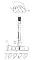
図1(a)は、市販の整形外科用タップに本発明に係る穿孔刃の働き幅を調整するための二重円筒管構造からなるアタッチメント1を装着(被嵌)した際のタップの正面図であり、図1(b)は、X−X線断面図である。なお、アタッチメント1を装着するタップは上記構成と同様であるので、各部を示す番号も便宜上図と同じ番号を用いる。
【0021】
アタッチメント1は、図1に示すように第一筒体10とそれよりやや小径の第二筒部20とから構成してある。
【0022】
第一筒体10は、その上端から第二筒体20を挿通可能なような内径に成形してある。そして、第一筒体10の胴部に基端から先端方向に走るガイド窓10aを開設し、第二筒体20を挿通した状態でガイド窓10aに位置規制ピン10bを挿入して第二筒体20と第一筒体10とを連結してある。これにより、タップに装着しない状態ではガイド窓10aの長さぶん第二筒体20は第一筒体10に対して出退することによって自由にスライドするようになっている。
【0023】
また、このような第二筒体20のスライド量が判るように、第二筒体20の周面には、上記位置規制ピン10bがガイド窓10aの壁面に当接する最上端に位置するときに(図1(a),(b))、第一筒体10の上端縁10c(指示部)の位置を基点(ゼロ)として、先端側に向けて当該上端縁10cで読み取る目盛りM1を所定間隔(例えば、0.2cm間隔)に形成してある。なお、第二筒体20の先端部分は、タップを体内に挿入する際に生じる抵抗を小さくしてタップを挿入しやすいように先端方向に次第に外径が小さいテーパ部20bを形成してある。
【0024】
このようなアタッチメント1を、第一筒体の上端縁10cを目盛りゼロの位置(これを基準位置という。)に合わせたときに、第二筒体20の上端縁20aがねじ部202の先端202aと面一に揃うように第一筒体10の基端をねじ11によって軸体に対して締付固定してある。このようにアタッチメント1をタップに装着することにより、図2に示すように上記基準位置からの第二筒体20を後退させた量だけ、つまり第一筒体10の指示部である上端縁10cが示す指示値に相当するぶんだけ、ねじ部202の第二筒体上端からの突出量が変更できるようにしてある(図2(a)、(b)参照。図2は、筒体20を後退させたときの正面図を(a)に、Y−Y線断面図を(b)に示す。)。この変更したねじ部202の働き幅は、上記第二筒体20に取り付けられた締付具である位置規制ピン10bの締め込み量を増せば軸体201にこれが当接しその状態に固定されるようにしてある。このねじ部202の第二筒体上端からの突出量を刃部の「働き幅」と本明細書では定義する。
【0025】
なお、アタッチメント1の構成材料としては整形外科用タップに使用されるものと同等の材料(ステンレス、あるいは滅菌(EO,γ線,電子線なとによる滅菌)可能な材料)であればよい。従って、この材料には骨体を加工することに支障がない材料や、オートクレーブ滅菌による温度と圧力に反復して耐えられるものを用いることが好ましい。
【0026】
次に、上記構成を有する整形外科用タップ1の使用態様を図3を用いて以下に説明する。図3は、整形外科用タップ1が骨体Bに雌ねじを形成していく状態を示す図である。まず、最初は骨体の雌ねじを形成しようとする位置にドリルで下穴hを空けておく。次に、整形外科用タップ1を下穴hへねじ部202の先端を挿入する。
【0027】
ねじ部202の先端を下穴hに挿入すると、握り部203を時計方向に回転させることによりねじ部202を回転させて骨体Bに雌ねじを形成していく。この回転動により刃部204、204、・・・が螺旋状に動いて骨体Bを削りねじ溝を形成していく。
【0028】
このような動作によってねじ溝を形成していき、前述のように設定したねじ部202の所望の働き幅に対応した深さまでねじ部202を進めたところで柄203の回転を止める。ねじ部202が所望の深さまで達したか否かの判断は、ねじ部202近傍に設けた第二筒体20の上端縁20aが下穴hの入り口に達したか否かにより行う。これは、上端縁20aが患部に接触するのでねじ部202を回転させるためのトルクが大きくなったかどうかで知り得る。
【0029】
上記の工程を経た後、形成された雌ねじからねじ部202が離脱するように握り部203を反時計回りに回転させてねじ部202を下穴hから離脱させることにより、骨体Bへの雌ねじの形成が完了する。
【0030】
以上説明してきたように、上記アタッチメント1を装着した整形外科用タップによれば、ねじ部の働き幅を所望の値に設定することができるので、用いるねじの寸法に応じて正確に雌ねじを形成することができる。
【0031】
〔実施の形態2〕
上記実施の形態1は、穿孔刃の形成された軸体に二重円筒管の筒体を装着して、二重円筒管の一の円筒管をスライドさせることで、ねじ部の働き幅を調整する構成であったが、以下述べるような形態も穿孔刃の出退機構の一形態として挙げられる。本実施の形態に係る整形外科用ドリルは、ラチェット機構を設けて、穿孔刃の働き幅を調整できるようにしてある。
【0032】
図4は、本実施の形態に係る整形外科用ドリル100の組立図である。
【0033】
この図に示すように本整形外科用ドリル100は、軸体101、軸体101の先端部に位置する、複数の刃部104、104、・・・を螺旋状に設けて形成した切削部102、軸体101の基部に設けてある柄103、軸体101に筒体110を挿通して構成してあり、筒体を一定間隔毎に位置移動して軸体に対して固定する固定具としてラチェット機構を設けてある。
【0034】
筒体110は、端面には円周状に形成された追い切り刃111,111・・・を有し手術に用いるねじのねじ頭に相当する外径を有する小円筒部110a、その基端側には先端方向に次第に外径が小さくなるテーパ部110b、その更に基端側には使用者が把持しやすいようにやや大径の大径筒部110cを形成してある。この大径筒部110cは軸体の胴部101aに挿通でき且つ軸体101に被嵌したときに軸体101に対して回動しないようにするため、略角柱状の胴部101aの断面形状に相似した断面形状に筒体110の内周面は加工してある。
【0035】
図5は、図4における筒体を装着した状態での筒体の腰部を含むZ−Z線断面図であり、図6は、図4における筒体を装着した状態でのZ’−Z’線断面図である。
【0036】
ラチェット機構は、図6に示すように軸体101の胴部101aに一定間隔に形成したラチェット溝120,120,・・・と、筒体110の基端寄り部でその中心方向に付勢して設けたラチェット爪130とにより構成してある。つまり、ラチェット爪130はバネ131で付勢して、筒体110に取り付けてあるので、この付勢状態のときには、ラチェット溝120にラチェット爪130が係合し、後方(基端方向)へのスライドを規制する一方、ラチェット爪130とラチェット溝120との係合を解除すると後方にスライドするようになっている。これはラチェット爪130と連結させた押下板132を使用者が押下すると、ばね131による付勢力が解かれて図5に示すようにラチェット爪130がラチェット溝120から退避し、これによってラチェット爪130とラチェット溝120との係合状態が簡単に解除するためである。なお、図6において付勢状態にある上記押下板132を筒体110の表面から突出させてあるが、手術中に使用者がこれを誤ってこれを押下しないように、上記押下板132を筒体110の表面から埋没させても良い。
【0037】
また、ラチェット溝120,120,・・・は、図6に示すように基端側から次第に浅くなるよう傾斜面を設けて形成してあるため、上記押下板132を使用者が押下してラチェット溝120からラチェット爪130を退避させなくとも前方へ筒体110は自由にスライドする。これは、筒体110に付与される前方への押力に伴って、ラチェット溝120を形成する側壁がラチェット爪130を押し上げる力が発生するので、その押し上げ力によってラチェット爪120はラチェット溝120から退避してラチェット溝120とラチェット爪130との係合がその力だけで解除するからである。
【0038】
軸体101の胴部101aには、筒体上端縁112が切削部先端102aと面一に揃っている状態のとき筒体基端縁113(指示部)の位置を目盛りの基準点(ゼロ)として、筒体110の後退方向の移動量に相当(ラチェット溝の形成間隔に相当)する寸法で(例えば、0.2cm間隔)目盛りM2を形成してある(尚、図面では数値は付していないが実際には、該当する数値を付してある。)。
【0039】
このように、目盛り付けすることによって、筒体基端縁113が指示する値で切削部(刃部)の働き幅を規定することができる。
【0040】
この整形外科用ドリル100は、上記整形外科用タップ1を使用するに先立って患部に下穴hを開けるために用い、その使用態様は一般的な態様と同様であるのでここでの詳しい説明は省略するが、筒体110の先端部は追い切り刃111,111,・・・を有する円筒体となっているので、追い切り刃111,111,・・・で患部を掘削してゆきドリルは筒体110の先端縁よりも更に患部に埋没し、テーパ部110bの先端方向周面が患部と接触した時点で感じる抵抗により、下穴hの形成を終了することになる。従って、筒部110aが埋没した領域にはねじ頭部相当の径の孔が開設されることになり、ねじを患部にねじ込む場合に、頭部を患部の例えば骨表面から露出させることなく、患部に埋没させることができる。
【0041】
〔その他の事項〕
本発明は、上記実施の形態に限定されないのは言うまでもなく、発明の要旨を逸脱しない範囲において次のような変形例が考えられる。
【0042】
(1) 実施の形態1と実施の形態2とを比較すると実施の形態1のアタッチメントを用いて刃部の働き幅を調整する方が使用者にとっての利便性は高い。即ち、実施の形態1のように市販のタップにアタッチメントを装着して刃部の働き幅を調整するようにすれば、軸体にラチェット溝を形成したり目盛りを付したりすることが不要となるため、使用者は既に用いているタップを利用できるからである。
【0043】
(2) 上記実施の形態1のアタッチメント1における第二筒体を軸体に固定したが、第一筒体に固定するようにしてもよい。この場合、第一筒体側部からねじを締め込み第二筒体に当接することにより第二筒体を固定するようにする。従って、位置規制ピンは第一筒体に第二筒体を固定する固定具としての機能は有さず、固定具と位置規制ピンとは別体とする。
【0044】
(3) 上記実施の形態2において、目盛りを軸体、指示部を筒体に設けたが、目盛りを筒体、指示部を軸体に設けることもできる。
【0045】
(4) 実施の形態2においてラチェット機構を設けたがこれに限定されず、筒体を軸体に対してねじ締め固定するようなより簡略な構成とすることもできるが、ラチェット機構を設けた方が、作業時に基端方向へ作用する力に抗し刃部の働き幅設定値を確実に維持できる。
【0046】
(5) 上記実施の形態1において刃部の働き幅を調整するために装着したアタッチメント1は、整形外科用タップの他整形外科用ドリルにも適用することができ、また、実施の形態2におけるラチェット機構はタップに対しても同様に適用することができる。
【0047】
【発明の効果】
以上説明してきたように、本発明の整形外科用工具は、胴部が角柱形状であると共に、先端部に穿孔刃が形成された軸体と、軸体にスライド自在に被嵌される筒体と、筒体を軸体上に固定する固定具とを備え、前記筒体は、その前記胴部をスライドする部分の内周面の断面が、軸体に対して筒体が回動しないように前記胴部の断面形状と相似な形状であり、かつ、先端部には、小径円筒部とこれに続き前記胴部側に向けて径が大きくなるテーパ部とを備えると共に、その小径円筒部の先端面には、整形用のねじの頭部に相当する径の孔を形成する追い切り刃を有し、前記軸体には、その角柱形状の胴部の側面に穿孔刃の働き幅を表示するための目盛りが軸芯方向に沿って形成されてなる。
【0048】
これによって、タッピングやドリリングにおいて所望のねじ溝やねじ穴を形成することができる。
【図面の簡単な説明】
【図1】(a)は、一の実施の形態に係る二重円筒管構造からなるアタッチメント1を市販のタップに装着した際のタップの正面図である。(b)は、(a)図におけるX−X線断面図である。
【図2】(a)は、一の実施の形態に係る二重円筒管構造からなるアタッチメント1を市販のタップに装着した際のタップの別な正面図である。(b)は、(a)図におけるY−Y線断面図である。
【図3】上記整形外科用タップの使用態様を説明するための模式図である。
【図4】別な実施の形態に係る整形外科用タップの組立図である。
【図5】上記整形外科用タップの組立後のZ−Z線断面図である。
【図6】上記整形外科用タップの組立後のZ’−Z’線断面図である。
【図7】従来の整形外科用タップを示す正面図である。
【符号の説明】
1 アタッチメント
10 第一筒体
10a ガイド窓
10b 位置規制ピン
10c 上端縁
20 第二筒体
20a 上端縁
100 整形外科用ドリル
101 軸体
101a 胴部
102 切削部
102a 先端
103 柄
104 刃部
110 筒体
110a 小円筒部
110b テーパ部
110c 大径筒部
111 追い切り刃
112 筒体上端縁
113 筒体基端縁
120 ラチェット溝
130 ラチェット爪
131 バネ
132 押下板[0001]
TECHNICAL FIELD OF THE INVENTION
The present invention relates to an orthopedic tool such as an orthopedic tap or a drill used in a surgical procedure targeting a rigid object such as a bone, and in particular, to a drilling blade for piercing an orthopedic object by a rotating operation. It relates to technology for adjusting the working width.
[0002]
[Prior art]
Generally, in orthopedic surgery, there is an operation method in which a female screw needs to be formed in a bone body. For example, when reconstructing a tendon or ligament, it may be necessary to first form an internal thread in the bone to fix the artificial or harvested tendon or ligament to the bone. In forming such internal threads in a bone, first, a hole is drilled in the bone using an orthopedic drill, and then an internal thread is formed in the formed hole with an orthopedic tap. It is performed in the process.
[0003]
FIG. 7 shows a conventional example of this tap for orthopedic surgery. As shown in this figure, a conventional
[0004]
[Problems to be solved by the invention]
By the way, when forming an affected part screw groove using the tap having the above configuration, in most cases, formation of a desired screw groove is performed based on visual measurement by a doctor or the like. In addition, when blood adheres to the tool, it is extremely difficult to accurately form a desired thread groove.
[0005]
Whether or not the screw groove can be formed accurately affects the accuracy of the operation. In other words, if the formation region of the thread groove extends to a deep portion and the formation area is much larger than a desired amount, excess tissue may be damaged. On the other hand, if the formed screw groove is much smaller than the desired area, the screw cannot be sufficiently inserted. That is, it is desirable to perform tapping so that the formation area of the thread groove is as close to a desired value as possible.
[0006]
The above is a problem in tapping, but also occurs in so-called drilling in which a screw hole is formed in a bone with an orthopedic drill. That is, if the screw hole is too deep, there is a problem that the excess tissue is damaged, and if the formed screw hole is too shallower than the desired depth, the screw cannot be sufficiently fitted.
[0007]
The present invention has been made in view of the above problems, and has been made to provide an orthopedic tool such as a tap or a drill capable of forming a desired screw groove or screw hole.
[0008]
[Means for Solving the Problems]
In order to achieve the above object, anorthopedic tool according to the present inventionhas a barrel having a prismatic shape, a bore having a perforated blade formed at a distal end thereof, and a cylinder slidably fitted on the barrel. Body, and a fixture for fixing the cylindrical body on the shaft body, wherein the cylindrical body has a cross section of an inner peripheral surface of a portion where the body slides, and the cylindrical body does not rotate with respect to the shaft body As described above, the body has a shape similar to the cross-sectional shape of the body, and has a small-diameter cylindrical part and a tapered part having a diameter increasing toward the body following the small-diameter cylindrical part at the tip, and the small-diameter cylindrical part. The tip surface of the portion has a chasing blade which forms a hole having a diameter corresponding to the head of a shaping screw. A scale for displaying the width is formed along the axis direction.
[0009]
Thereby, a desired screw groove or screw hole can be formed in tapping or drilling.
[0010]
The fixing tool may be composed of a ratchet groove formed on the shaft and a ratchet claw provided on the cylinder.
[0011]
Further, according to thepresent invention, the scale is formed such that the base end of the cylinder points to the reference point when the tip of the cylinder is aligned with the tip of the shaft, and corresponds to the amount of movement of the cylinder in the retreating direction. It is characterized in that the scale is formed with the dimensions as described below.
[0015]
Thus, a desired screw groove or screw hole can be formed in tapping or drilling simply by positioning and attaching the attachment to a commercially available orthopedic tool.
[0019]
BEST MODE FOR CARRYING OUT THE INVENTION
Examples of the orthopedic tool of the present invention include a tap for forming a screw groove in a diseased part such as a robust bone and a drill for opening a screw hole. In the following embodiments, an orthopedic tap which is one of them is described. This will be specifically described with reference to the drawings.
[0020]
[Embodiment 1]
FIG. 1A is a front view of a commercially available orthopedic tap when an
[0021]
As shown in FIG. 1, the
[0022]
The
[0023]
Further, as can be seen from the slide amount of the second
[0024]
When such an
[0025]
The material of the
[0026]
Next, a usage mode of the
[0027]
When the tip of the
[0028]
The screw groove is formed by such an operation, and when the
[0029]
After the above process, the
[0030]
As described above, according to the orthopedic tap equipped with the
[0031]
[Embodiment 2]
In the first embodiment, the working width of the screw portion is adjusted by attaching the cylindrical body of the double cylindrical tube to the shaft body with the drilling blade and sliding one cylindrical tube of the double cylindrical tube. However, the form described below can also be cited as one form of the retracting mechanism of the boring blade. The orthopedic drill according to the present embodiment is provided with a ratchet mechanism so that the working width of the drilling blade can be adjusted.
[0032]
FIG. 4 is an assembly view of the
[0033]
As shown in this drawing, the
[0034]
The
[0035]
FIG. 5 is a sectional view taken along the line ZZ including the waist of the tubular body in a state in which the tubular body in FIG. 4 is mounted, and FIG. 6 is a view Z'-Z 'in a state in which the tubular body in FIG. It is a line sectional view.
[0036]
As shown in FIG. 6, the ratchet mechanism urges the
[0037]
Since the
[0038]
When the
[0039]
In this way, by setting the scale, the working width of the cutting portion (blade portion) can be defined by the value indicated by the
[0040]
This
[0041]
[Other matters]
Needless to say, the present invention is not limited to the above-described embodiment, and the following modifications may be made without departing from the spirit of the invention.
[0042]
(1) Comparing
[0043]
(2) Although the second cylinder in the
[0044]
(3) In the second embodiment, the scale is provided on the shaft, and the indicator is provided on the cylinder, but the scale may be provided on the cylinder and the indicator may be provided on the shaft.
[0045]
(4) Although the ratchet mechanism is provided in the second embodiment, the present invention is not limited to this, and a simpler configuration in which the cylindrical body is screwed and fixed to the shaft body can be adopted. However, the ratchet mechanism is provided. By doing so, the working width set value of the blade portion can be reliably maintained against the force acting in the proximal direction during work.
[0046]
(5) The
[0047]
【The invention's effect】
As described above, the orthopedic tool according to the present invention has acylindrical body having a prismatic shape at the trunk and a perforated blade formed at the tip, and a cylindrical body slidably fitted on the shaft. And a fixing device for fixing the cylinder on the shaft, wherein the cylinder has a cross section of an inner peripheral surface of a portion where the body slides so that the cylinder does not rotate with respect to the shaft. The body has a shape similar to the cross-sectional shape of the body, and at the tip, a small-diameter cylindrical part and a tapered part having a diameter increasing toward the body following the small-diameter cylindrical part, and the small-diameter cylindrical part is provided. The tip surface has a chasing blade which forms a hole having a diameter corresponding to the head of a shaping screw, and the shaft has a working width of a drilling blade on a side surface of the prismatic body. The scale for displaying is formed along the axis direction.
[0048]
Thereby, a desired screw groove or screw hole can be formed in tapping or drilling.
[Brief description of the drawings]
FIG. 1A is a front view of a tap when an
FIG. 2A is another front view of the tap when the
FIG. 3 is a schematic view for explaining a usage mode of the orthopedic tap.
FIG. 4 is an assembly view of an orthopedic tap according to another embodiment.
FIG. 5 is a sectional view taken along the line ZZ of the orthopedic tap after assembly.
FIG. 6 is a sectional view taken along the line Z′-Z ′ after the orthopedic tap is assembled.
FIG. 7 is a front view showing a conventional orthopedic tap.
[Explanation of symbols]
DESCRIPTION OF
Claims (3)
Translated fromJapanese軸体にスライド自在に被嵌される筒体と、
筒体を軸体上に固定する固定具と
を備え、
前記筒体は、
その前記胴部をスライドする部分の内周面の断面が、軸体に対して筒体が回動しないように前記胴部の断面形状と相似な形状であり、かつ、
先端部には、小径円筒部とこれに続き前記胴部側に向けて径が大きくなるテーパ部とを備えると共に、その小径円筒部の先端面には、整形用のねじの頭部に相当する径の孔を形成する追い切り刃を有し、
前記軸体には、その角柱形状の胴部の側面に、穿孔刃の働き幅を表示するための目盛りが軸芯方向に沿って形成されてなることを特徴とする整形用外科工具。A shaft having a body shaped like a prism and a perforated blade formed at the tip,
A cylindrical body slidably fitted on the shaft body,
And a fixture for fixing the cylinder on the shaft,
The cylinder is
The cross section of the inner peripheral surface of the part that slides the trunk is similar in shape to the cross section of the trunk so that the cylinder does not rotate with respect to the shaft, and
The distal end portion has a small-diameter cylindrical portion and a tapered portion having a diameter increasing toward the body portion following the small-diameter cylindrical portion, and the distal end surface of the small-diameter cylindrical portion corresponds to a head of a shaping screw. It has a chasing blade that forms a hole with a diameter,
An orthopedic surgical tool, characterized in that a scale for indicating the working width of a drilling blade is formed along the axial direction on a side surface of a prismatic body of the shaft body.
Priority Applications (1)
| Application Number | Priority Date | Filing Date | Title |
|---|---|---|---|
| JP35885497AJP3581245B2 (en) | 1997-12-26 | 1997-12-26 | Orthopedic tools |
Applications Claiming Priority (1)
| Application Number | Priority Date | Filing Date | Title |
|---|---|---|---|
| JP35885497AJP3581245B2 (en) | 1997-12-26 | 1997-12-26 | Orthopedic tools |
Publications (2)
| Publication Number | Publication Date |
|---|---|
| JPH11188043A JPH11188043A (en) | 1999-07-13 |
| JP3581245B2true JP3581245B2 (en) | 2004-10-27 |
Family
ID=18461448
Family Applications (1)
| Application Number | Title | Priority Date | Filing Date |
|---|---|---|---|
| JP35885497AExpired - Fee RelatedJP3581245B2 (en) | 1997-12-26 | 1997-12-26 | Orthopedic tools |
Country Status (1)
| Country | Link |
|---|---|
| JP (1) | JP3581245B2 (en) |
Families Citing this family (15)
| Publication number | Priority date | Publication date | Assignee | Title |
|---|---|---|---|---|
| US20030220646A1 (en)* | 2002-05-23 | 2003-11-27 | Thelen Sarah L. | Method and apparatus for reducing femoral fractures |
| US7258692B2 (en) | 2000-03-07 | 2007-08-21 | Zimmer, Inc. | Method and apparatus for reducing femoral fractures |
| US7488329B2 (en) | 2000-03-07 | 2009-02-10 | Zimmer Technology, Inc. | Method and apparatus for reducing femoral fractures |
| JP2002090899A (en)* | 2000-09-13 | 2002-03-27 | Noritsu Koki Co Ltd | Reel for photosensitive material |
| US7338494B2 (en)* | 2003-08-19 | 2008-03-04 | Synthes (U.S.A.) | Spring-loaded awl |
| CN101816588A (en)* | 2004-02-20 | 2010-09-01 | 赫克托·O·帕切科 | Adjustable awl for punching |
| US7488327B2 (en) | 2004-04-12 | 2009-02-10 | Synthes (U.S.A.) | Free hand drill guide |
| US20060229624A1 (en) | 2005-03-31 | 2006-10-12 | Zimmer Technology, Inc. | Orthopaedic cutting instrument and method |
| JP5797898B2 (en)* | 2010-12-28 | 2015-10-21 | タキロン株式会社 | Bone tap jig |
| CN103841907B (en)* | 2011-02-15 | 2019-06-14 | 史密夫和内修有限公司 | Arthroscope device for excising |
| JP5107468B1 (en)* | 2012-02-01 | 2012-12-26 | 順 岡田 | Surgical bone drill drill stopper |
| US9572589B2 (en)* | 2012-07-10 | 2017-02-21 | Stryker European Holdings I, Llc | Drill guide |
| CN105832378B (en)* | 2016-06-12 | 2018-07-13 | 贵州梓锐科技有限公司 | Abrasion drill for orthopedic operation |
| CN108113731B (en)* | 2017-12-29 | 2020-07-31 | 鹤壁市人民医院 | Bone nail countersink drill for orthopedics |
| JP7470993B2 (en)* | 2021-04-28 | 2024-04-19 | 株式会社東鋼 | Drill |
- 1997
- 1997-12-26JPJP35885497Apatent/JP3581245B2/ennot_activeExpired - Fee Related
Also Published As
| Publication number | Publication date |
|---|---|
| JPH11188043A (en) | 1999-07-13 |
Similar Documents
| Publication | Publication Date | Title |
|---|---|---|
| JP3581245B2 (en) | Orthopedic tools | |
| US12310601B2 (en) | Kit including a guiding system and a bone material removal device | |
| EP3344165B1 (en) | Powered surgical drill with integral depth gauge that includes a probe that slides over the drill bit | |
| CA2876440C (en) | Transbuccal plate holding cannula | |
| EP0984840B1 (en) | Drilling guide and measuring instrumentation | |
| US4798213A (en) | Bone biopsy apparatus | |
| US5645547A (en) | Revisable interference screw | |
| US7823296B2 (en) | Depth gauge | |
| JP4421157B2 (en) | Safety device with a stopper for a drilling instrument used in oral surgery and a device for pre-calibrating and storing the drilling depth | |
| CA2308629C (en) | Apparatus for frameless stereotactic surgery | |
| US6096042A (en) | Driver | |
| US5011473A (en) | Device for securing and positioning a wire to a needle | |
| US20150018831A1 (en) | Retrodrill system | |
| EP3512440B1 (en) | Multiple head drill | |
| US9289219B2 (en) | Drill bit incorporating depth gauge | |
| CN114601535B (en) | Planing tool insertion device capable of adjusting circumferential angle and planing handle | |
| US12369929B2 (en) | Retrograde drilling device | |
| CN102846349B (en) | A kind of vertebral canal expansion Wicresoft cutting tool | |
| CN110432972B (en) | Orthopedics is with directly going into formula ke shi needle propeller | |
| JP3323747B2 (en) | Orthopedic tap | |
| CN213787541U (en) | Skin disease skin damage sampler | |
| CN219895839U (en) | Visual screw tap assembly | |
| CN113647996A (en) | A vertebral body bone tumor sampling device | |
| JPH09503413A (en) | Gauge for bone marrow lumen |
Legal Events
| Date | Code | Title | Description |
|---|---|---|---|
| A131 | Notification of reasons for refusal | Free format text:JAPANESE INTERMEDIATE CODE: A131 Effective date:20040120 | |
| A521 | Written amendment | Free format text:JAPANESE INTERMEDIATE CODE: A523 Effective date:20040322 | |
| TRDD | Decision of grant or rejection written | ||
| A01 | Written decision to grant a patent or to grant a registration (utility model) | Free format text:JAPANESE INTERMEDIATE CODE: A01 Effective date:20040622 | |
| A61 | First payment of annual fees (during grant procedure) | Free format text:JAPANESE INTERMEDIATE CODE: A61 Effective date:20040722 | |
| R150 | Certificate of patent or registration of utility model | Free format text:JAPANESE INTERMEDIATE CODE: R150 | |
| FPAY | Renewal fee payment (event date is renewal date of database) | Free format text:PAYMENT UNTIL: 20080730 Year of fee payment:4 | |
| FPAY | Renewal fee payment (event date is renewal date of database) | Free format text:PAYMENT UNTIL: 20080730 Year of fee payment:4 | |
| FPAY | Renewal fee payment (event date is renewal date of database) | Free format text:PAYMENT UNTIL: 20090730 Year of fee payment:5 | |
| FPAY | Renewal fee payment (event date is renewal date of database) | Free format text:PAYMENT UNTIL: 20100730 Year of fee payment:6 | |
| FPAY | Renewal fee payment (event date is renewal date of database) | Free format text:PAYMENT UNTIL: 20110730 Year of fee payment:7 | |
| LAPS | Cancellation because of no payment of annual fees |