JP3580427B2 - Reconfigurable parameterized DTMF detector - Google Patents
Reconfigurable parameterized DTMF detectorDownload PDFInfo
- Publication number
- JP3580427B2 JP3580427B2JP50476592AJP50476592AJP3580427B2JP 3580427 B2JP3580427 B2JP 3580427B2JP 50476592 AJP50476592 AJP 50476592AJP 50476592 AJP50476592 AJP 50476592AJP 3580427 B2JP3580427 B2JP 3580427B2
- Authority
- JP
- Japan
- Prior art keywords
- dtmf
- signal
- input
- test
- amplitude
- Prior art date
- Legal status (The legal status is an assumption and is not a legal conclusion. Google has not performed a legal analysis and makes no representation as to the accuracy of the status listed.)
- Expired - Fee Related
Links
- 238000012360testing methodMethods0.000claimsdescription116
- 238000004891communicationMethods0.000claimsdescription27
- 238000012545processingMethods0.000claimsdescription27
- 238000000034methodMethods0.000claimsdescription20
- 238000005070samplingMethods0.000claimsdescription15
- 230000007704transitionEffects0.000claimsdescription7
- 230000009977dual effectEffects0.000claimsdescription5
- 230000005540biological transmissionEffects0.000claimsdescription2
- 230000005236sound signalEffects0.000claimsdescription2
- 241000283203OtariidaeSpecies0.000claims2
- 238000004458analytical methodMethods0.000description8
- 238000010586diagramMethods0.000description7
- 230000006870functionEffects0.000description4
- 238000001514detection methodMethods0.000description3
- 238000009434installationMethods0.000description3
- 230000007257malfunctionEffects0.000description3
- 239000011159matrix materialSubstances0.000description3
- 230000011664signalingEffects0.000description3
- 230000000694effectsEffects0.000description2
- 238000001914filtrationMethods0.000description2
- 238000003825pressingMethods0.000description2
- 238000011160researchMethods0.000description2
- 238000003775Density Functional TheoryMethods0.000description1
- 238000004364calculation methodMethods0.000description1
- 230000001413cellular effectEffects0.000description1
- 238000012937correctionMethods0.000description1
- 230000007547defectEffects0.000description1
- 238000005516engineering processMethods0.000description1
- 238000013095identification testingMethods0.000description1
- 238000004377microelectronicMethods0.000description1
- 238000005457optimizationMethods0.000description1
- 238000013341scale-upMethods0.000description1
- 230000035945sensitivityEffects0.000description1
- 238000004088simulationMethods0.000description1
- 238000003860storageMethods0.000description1
Images


Classifications
- H—ELECTRICITY
- H04—ELECTRIC COMMUNICATION TECHNIQUE
- H04Q—SELECTING
- H04Q1/00—Details of selecting apparatus or arrangements
- H04Q1/18—Electrical details
- H04Q1/30—Signalling arrangements; Manipulation of signalling currents
- H04Q1/44—Signalling arrangements; Manipulation of signalling currents using alternate current
- H04Q1/444—Signalling arrangements; Manipulation of signalling currents using alternate current with voice-band signalling frequencies
- H04Q1/46—Signalling arrangements; Manipulation of signalling currents using alternate current with voice-band signalling frequencies comprising means for distinguishing between a signalling current of predetermined frequency and a complex current containing that frequency, e.g. speech current
- H—ELECTRICITY
- H04—ELECTRIC COMMUNICATION TECHNIQUE
- H04M—TELEPHONIC COMMUNICATION
- H04M3/00—Automatic or semi-automatic exchanges
- H04M3/42—Systems providing special services or facilities to subscribers
- H04M3/50—Centralised arrangements for answering calls; Centralised arrangements for recording messages for absent or busy subscribers ; Centralised arrangements for recording messages
- H04M3/53—Centralised arrangements for recording incoming messages, i.e. mailbox systems
- H04M3/533—Voice mail systems
- H—ELECTRICITY
- H04—ELECTRIC COMMUNICATION TECHNIQUE
- H04Q—SELECTING
- H04Q1/00—Details of selecting apparatus or arrangements
- H04Q1/18—Electrical details
- H04Q1/30—Signalling arrangements; Manipulation of signalling currents
- H04Q1/44—Signalling arrangements; Manipulation of signalling currents using alternate current
- H04Q1/444—Signalling arrangements; Manipulation of signalling currents using alternate current with voice-band signalling frequencies
- H04Q1/45—Signalling arrangements; Manipulation of signalling currents using alternate current with voice-band signalling frequencies using multi-frequency signalling
- H04Q1/453—Signalling arrangements; Manipulation of signalling currents using alternate current with voice-band signalling frequencies using multi-frequency signalling in which m-out-of-n signalling frequencies are transmitted
- H—ELECTRICITY
- H04—ELECTRIC COMMUNICATION TECHNIQUE
- H04Q—SELECTING
- H04Q1/00—Details of selecting apparatus or arrangements
- H04Q1/18—Electrical details
- H04Q1/30—Signalling arrangements; Manipulation of signalling currents
- H04Q1/44—Signalling arrangements; Manipulation of signalling currents using alternate current
- H04Q1/444—Signalling arrangements; Manipulation of signalling currents using alternate current with voice-band signalling frequencies
- H04Q1/45—Signalling arrangements; Manipulation of signalling currents using alternate current with voice-band signalling frequencies using multi-frequency signalling
- H04Q1/457—Signalling arrangements; Manipulation of signalling currents using alternate current with voice-band signalling frequencies using multi-frequency signalling with conversion of multifrequency signals into digital signals
Landscapes
- Engineering & Computer Science (AREA)
- Computer Networks & Wireless Communication (AREA)
- Signal Processing (AREA)
- Cable Transmission Systems, Equalization Of Radio And Reduction Of Echo (AREA)
Description
Translated fromJapanese発明の分野
この発明は、DTMF(デュアルトーンマルチフリクエンシー)信号処理を用いたデジタル通話システム、特にDTMF検出器に関する。
発明の背景
米国特許商標庁の先行技術調査によって、この発明に関連する先行技術であると判明したのは、米国特許第4,021,653号、第4,354,248号、第4,460,806号、第4,510,601号、第4,604,755号、第4,614,909号、第4,689,760号、第4,782,523号および第4,853,958号である。該特許はすべてDTMF検出器を開示しているが、本発明のような顧客の特定の要求やシステムの動作モードに応じて設定可能な検出器を開示するものではない。
DTMF標準は以下に挙げるベル研究所と電子工業会の6つの文献に定義されている(特に最初に挙げる文献)。
Bell Communications Research,″Dual−Tone Multifrequency Receiver Generic Requirements for End−to−End Signaling Over Tandem−Switched Voice Links″,TR−TSY−000181,Issue 1,1987年3月
Bell Communications Research,″Customer Line Signaling″.Section 6.2.TR−TSY−000064 LSSGR,1984年12月
Bell System,″Bell System Public Switched Telephone Service Interconnection Criteria For Domestic Public Land Mobile Radio Service,Domestic Public Cellular
Telecommunications Service,and Maritime Radio Service″,Bell System Technical Reference,No.326−1987,1981年12月
Bell System Technical Reference,″Description of the Analog Voiceband Interface Between the Bell System Local Exchange Lines and Terminal Equipment″,No.326−125,1983年1月
Engineering Department,″EIA Standard,Telephone Instruments With Loop Signaling For Voiceband Applications″,Electronic Industries Association,Issuel,RS−470,1981年1月
Engineering Department,″EIA Standard,Private Branch Exchange(PBX)Switching Equipment For Voiceband Applications″,Electronic Industries Association,RS−464,1979年12月
以下に示す3つの文献は、本発明の好ましい実施例において構成要素(後述するゴーツェル変換モジュール36)として使用されるゴーツェルプロセッサを開示している。
Hartung et al.″Dual−Tone Multifrequency Receiver Using the WE DSP32 Digital Signal Processor″,American Telephone & Telegraph Application Note.
Oppenhein et al.,Digital Signal Processing,Prentice−Hall,Inc.,第287ページないし第289ページ(1975年)
Mock,″Add DTMF generation and decoding to DSP uP desings″,Digital Signal Processing Applications with the TMS320 Family,Vol.l.Texas Instruments,第545ページないし第557ページ(1989年)
以下に示す2つの文献は、当該技術分野で使われているDTMFシステムを開示している。
Microelectronics Analog Communications Handbook,Mitel Corporation,第3−27ページないし第3−33ページ(1990年)。該文献には、設定不可能なDTMF検出器が開示されている。
Boston Technology Voice Processing Systems,″B.Technical Specification″,ACCESSTMSERIERS Technical Manual,第B−1ページないし第B−18ページ。該文献の第B−8ページには、音声検出可能最小期間は16msecから100msecの間で設定可能である旨が開示されているが、他の特性(パラメータ)が設定可能であるという示唆や、音声検出可能最小期間がモード間で設定可能であるという示唆は一切ない。本発明では、たった1つの特性(パラメータ)ではなく16ものパラメータ群が設定可能である。即ち、各パラメータ群は4つの動作モード間で設定可能であり、よって、合計64の設定可能なパラメータ群が使用できる。
発明の概要
本発明はリアルタイムデジタル通話システム10においてDTMF信号を検出するための装置及び方法に関する。入力線(11,12)上の入力信号はDTMF信号、オーディオ信号、ビデオ信号、データ信号及び/またはノイズ信号を含んでいる。決定手段(後述するヒューリスティックスエンジン37)は、DTMF信号が入力信号中に存在するかどうかを決定し、入力として入力信号と、入力信号中のDFMF信号の複数のトーン特性をそれぞれ表す(構成要素(後述するメモリ38)に格納された)パラメータ群とを取り込む。パラメータ群はすべてユーザーによって設定可能であり、これによってトークオフ効果が最小限に抑えられて非標準電話器(13,14)のデジタル通話システム10での使用が可能となる。
【図面の簡単な説明】
本発明のこれらの目的や他の目的、特徴は以下の詳細な説明とこれに対応する以下の図面からより明らかになるであろう。
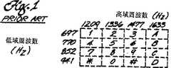
第1図は、従来のDTMF端末(プッシュボタン式電話機のプッシュボタンなどのような)からの、マトリクスをなすDTMF周波数の対が、各キーに対応している様子を示す図、
第2図は、最小受信期間のDTMFトーンに重ねた本発明の好ましい実施例にかかるデジタルサンプリングフレームを示すタイミングチャート、
第3図は、本発明の動作態様を示したシステムレベルの模式図、
第4図は、本発明の好ましい実施例に係る各デジタル信号プロセッサ31内の主要機能モジュールを示す模式図、
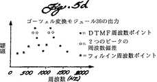
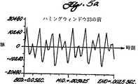
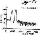
第5aないし5d図は、第4図の模式図の様々なモジュールでの処理工程におけるDTMFの数字1をアナログで表現した図、
第6図は、好ましい実施例に係るヒューリスティックスエンジン37の動作モードを示す図である。
詳細な説明
現代のデジタル通話システム10の要となるのは以下の説明においてマスターコンピュータとして説明されるようなコンピュータである。その様なコンピュータの1例がDigital Sound Corporationのパンフレット″DSC 2000 Voice ServerTM:The Fast Track to Digital Voice Processing″に開示されており、該文献を本発明の従来技術として引用する。マスターコンピュータ(デジタル通話システム10)との主なインターフェース手段は、例えば電話機13,14のプッシュボタンキーを押すことによって生成されるDTMF(デュアルトーンマルチフリクエンシー)信号である。各DTMFの数字は2つの正弦波信号成分の組み合わせからなる。DTMFキーは、一般的には、第1図に示すように4列×3行または4列×4行のマトリクス状に配置される。マトリクスの各交点でDTMFの数字を定義する2つの周波数コンポーネントが特定される。上述したように、ベル研究所と電子工業会の文献によれば、数字に関する多数の基準を有効DTMFの数字として登録する必要がある。
DTMF検出条件は十分に特定されているが、実用的ではない。市場には、特定されたトーン特性のうちある1つのトーン特性または複数のトーン特性を満足しない電話機13,14が多数存在する。その様な電話機13,14をデジタル通話システム10に接続した場合、動作不良がしばしば発生する。例えば、ねじれ仕様を越える電話機13,14では、プッシュボタンキーを押してもボタンの押下が認識されない。
他の動作不良としては、トークオフモードが挙げられる。トークオフはマスターコンピュータ(デジタル通話システム10)が音声信号やノイズなどの非DTMF信号をDTMF信号と誤認した場合に発生する。その結果、デジタル通話システム10が誤動作してしまう。検出器のトークオフに対する許容限度は、検出器のトークオフに対する感受性を判定するBellcoreのDTMF Digit Simulation Test Tapeを使って決定可能である。本発明は、パラメータ群については、トークオフを最小限に抑えるために、例えば、「必要フレームオン」を3から4に増加させる(40msecから51msecへの増加に対応する)などの変更が可能である。
本発明の目的は、DTMFの認識パラメータを、配設された特定の電話機13,14に応じて変更かつ設定可能な、パラメータ化されたDTMF検出器を得ることである。設定可能に構成することにより、本発明では他の設置場所(デジタル通話システム10)への配設に関係なくある設置場所(デジタル通話システム10)に非標準の電話機13,14を収容させるために必要な修正処理を行うことが可能である。
ところで、DTMFの数字を表現するトーン特性としては多数の異なるトーン特性があることを知るのは重要である。これらのトーン特性は、2つの周波数の絶対振幅、公称周波数からの偏差、低減ピークと高域ピークとの間の振幅の差、帯域外エネルギー、フレーム間の振幅の一貫性、および継続時間に関係している。本発明では、上記6つのトーン特性に対応する16のパラメータ群が用いられ、各パラメータ群は4つの動作モード間で変更可能であるので合計64の設定可能なパラメータ群が用いられる。このように設定可能に構成することにより、現場の支援技師はDTMF認識環境(デジタル通話システム10)を変更することができる。
本発明で使用される16のパラメータ群は以下のように定義されている。各パラメータについて、本明細書で後述するテストに照らして理解するようにすれば、各定義の意味はより明確となろう。
absm−公称DTMF信号のdBm単位での絶対振幅。
delta−フレーム間で各DFT(離散フーリエ変換)振幅が状態1の初期値に基づいて維持される、dB単位でのレンジ(許容範囲)。
fdi−周波数偏差指数。0,1,2のいずれかであり、実際の振幅ピークの周波数と公称DTMF振幅ピークの周波数との間の偏差はそれぞれ2%、2.5%、3%である。
h21t−高から低へのdB単位でのねじれ。即ち、高域振幅ピークの方が大きい場合の高域振幅ピークと低域振幅ピークとの間の差。
12ht−低から高へのdB単位でのねじれ。即ち、低域振幅ピークの方が大きい場合の低域振幅ピークと高域振幅ピークとの間の差。
cons−フレーム間のdB単位での一貫性、正規化DFT振幅のフレーム間の一貫性が測定される。
rfon−必要フレームオン。実際のDTMF信号であるという判断を下すために、候補DTMF信号が存在しなければならない全フレームの数を表す正の整数。
rfoff−必要フレームオフ。DTMF信号が実際には存在しないという判断を下すために、候補DTMF信号が存在してはならない全フレームの数を表す正の整数。
echo0−エコーテスト0のしきい値を表すdBm単位での絶対値。
efl0−エコーテスト0のためのdB単位でのエコーファクターロー。候補DTMF信号の振幅は、エコーテスト0での比較において必ずエコーファクターロー以上分だけ他の信号より大きくなければならない。
efh0−エコーテスト0のためのdB単位でのエコーファクターハイ。候補DTMF信号の振幅は、エコーテスト0での比較において必ずエコーファクターハイ以上分だけ他の信号の振幅より大きくなければならない。
efx0−エコーテスト0のためのdB単位でのエコーファクターx。候補DTMF信号の振幅は、エコーテスト0での比較において必ずエコーファクターx以上分だけ他の信号の振幅より大きくなければならない。
echol−エコーテスト1のしきい値を表すdBm単位での絶対値。
efll−エコーテスト1のためのdB単位でのエコーファクターロー。候補DTMF信号の振幅は、エコーテスト1での比較において必ずエコーファクターロー以上分だけ他の信号の振幅より大きくなければならない。
efhl−エコーテスト1のためのdB単位でのエコーファクターハイ。候補DTMF信号の振幅は、エコーテスト1での比較において必ずエコーファクターハイ以上分だけ他の信号の振幅より大きくなければならない。
efxl−エコーテスト1のためのdB単位でのエコーファクターx。候補DTMF信号の振幅は、エコーテスト1での比較において必ずエコーファクターx以上分だけ他の信号の振幅より大きくなければならない。
図に示したデジタル通話システム10においては4つの動作モードがあり、各動作モードの定義は以下のとおりである。
1デフォルトモード マイクロプロセッサ21がメッセージファイル22への記録もファイル22からの情報の処理も行っていない場合のモード。メッセージファイル22は、例えば、ハードディスク上のデジタル記憶領域であり、デジタルメッセージがマイクロプロセッサ21によって格納される。メッセージファイル22にはオーディオ、データ、ビデオやこれらの組み合わせが格納される。
2記録モード マイクロプロセッサ21がメッセージファイル22に情報を記録するときのモード
3メッセージモード メッセージファイル22からの未処理のメッセージを処理するとき(ユーザー電話機13,14への再送信)のモード。未処理のメッセージとは、外部ソースから電話線11,12を経て入力され、後で破壊されるメッセージである。図の実施例では、メッセージファイル22は、Digital Sound Corporationがリアルタイムデータ処理のために特別に開発した″UnivoxTM″オペレーティングシステム内のユニックスタイプのファイルである。UnivoxTMは、American Telephone & Telegraph Co.のユニックスシステムVリリース3との間に完全な互換性を有する。
4プロンプトモード 処理済みメッセージファイル22からの処理済みメッセージ、即ち定義済みメッセージを処理するときのモード(プロンプト)。トークオフ感受性についてプロンプト22を前もってテストできる。これは未処理のメッセージファイル22については不可能であり、これがメッセージモードとプロンプトモードを区別する第1の理由である。
メッセージモードとプロンプトモードを区別する第2の理由は,電話線(2線回線)11,12上のプロンプトにわたって(最小で−36dBmレベルに近い)長距離DTMFの数字を認識することができるようにするためである。電話アナログ電子分野では,4線から2線への変換を行う場合には必ず出発信号の一部が入力信号にエコーとして戻ってくる。その結果、入力信号の質が低下してしまい、数字にエラーが発生してしまう。プロンプトがトークオフを起こさないということがテストできるので、質の悪いDTMFの取り込みが可能となるようにコンピュータ(デジタル通話システム10)を設定してプロンプトモードにおけるDTMF認識動作を改善することができる。したがって、デジタル通話システム10内のDTMF検出器をその動作モードに応じて設定可能とすることが重要である。
本実施例では、64のパラメータ群のそれぞれについて、DTMFコンフィギューションハブと呼ばれる標準コンフィギュレーション群が経験的に生成され、メモリ(RAM)38に格納される(第4図)。各ハブは、大多数のデジタル通話システム10内のDTMF検出器の要求を満足するデフォルトパラメータ群を持っている。他のパラメータ群は典型的な問題であるところのシングルポイント不良を取り扱う。例えば、PBX(構内交換機)電話システムでは、すべての有効DTMF信号がねじれテスト(マイナス8dBの負のねじれとプラス4dBの正のねじれ)で不合格となる可能性がある。デジタル通話システム10の伝達機能によって信号が変化して有効DTMF信号がテストに不合格となってしまうのである。そこで、ねじれパラメータの特定のパラメータ群をこのデジタル通話システム10に用いれば、この不良を是正することができる。また、他の例としては、顧客がトークオフを起こしやすい個人電話機13,14を多数持つ場合である。トークオフの主な原因は、ベル研究所と電子工業会の40msec期間の仕様が短かすぎることである。トークオフを完全に解消することは不可能であるが、トークオフの可能性が高い場合に顧客がDTMFの数字を有効化するための最小期間を長く設定できるようにすれば、音声に似たDTMFの発生回数を低減することができる。トレードオフは、有効DTMFの数字の入力に時間がかかるという点である。
パラメータ群を改変する場合のトレードオフは常にトークオフである。もしパラメータ群を非標準の電話機13,14に適合するようにゆるくすれば、トークオフの発生が多くなる。
以下の表1は、4つの動作モードのそれぞれにおける16のパラメータ群の各々に対する64のデフォルトパラメータ群を示している。
第3図からわかるように、コンピュータ(デジタル通話システム10)は、システム制御部20と、ラインインターフェース制御部(LIC)30と、ラインインターフェースモジュール(LIM)40とを備えている。アナログ電話線11はユーザー電話機13をLIM40に接続する。アナログ信号はLIM40内に設けられたローパスフィルター41を通される。フィルター41はエイリアシング防止フィルターとして機能する。即ち、ナイキストウィンドウ外の高周波を除去する働きをする。フィルタリングされた信号は、やはりLIM40内に設けられたアナログ/デジタル変換器42に送られる。本実施例では、A/D変換器42内でのサンプリング速度は8000Hzである。最も高い公称DTMF周波数が1633Hzであってもサンプリング速度はこのように比較的早い速度とされるが、これは、この時点では信号にDTMF信号以外の信号、例えば声などが含まれており、また、ナイキスト基準によればデジタルサンプリング周波数は少なくともアナログ周波数の2倍でなければならないからである。
A/D変換器42の出力としては、256レベル(8ビット)のデジタル信号が得られ、この信号はTDMバス16からLIC30へと与えられる。時分割多重(TDM)技術を用いて、TDMバス16で複数のユーザー電話機13、14を同時に取り扱う。LIC30に入力されたデータはCODECまたは、PCM A−LawまたはMu−Law標準に準じて符号化されなければならない。
本発明はアナログ電話線11と同様にデジタル電話線12にも対応可能である。この場合、ユーザー電話機14はT1LIM(ラインインターフェースモジュール)43およびTDMバス16を介してデジタル電話線12からLIC30へと通信を行う。
システム制御部20はマイクロプロセッサ21を備えており、本実施例ではマイクロプロセッサ21としてはユニックスオペレーティングシステム上で走るIntelの80386マイクロプロセッサを使用している。システム制御部20は、マルチバス15を介してLIC30およびLIM40と2方向通信を行う。
LIC30も同様にIntelの80386マイクロプロセッサ32と、一群のデジタル信号プロセッサ(DSP)31とを備えている。実施例では、DSP31は8個であり、それぞれが2本から3本の電話線11,12をサポートできるようになっている。各DSP31は好ましくはTexas InstrumentsのTMS320C25である。電話線11,12の本数が少ない場合にはTMS32010を用いてもよい。
第4図に図示するように、各デジタル信号プロセッサ31内には一群のモジュール(典型的にはソフトウェアを備えたRAM)が設けられており、システム制御部20の制御下で一連の処理が行われる。
第2図は期間が40msecの公称DTMFトーンに重ね合わされた一群のフレームを図示している。フレームとは、一連のフーリエ変換がゴーツェル変換モジュール36によって行われるサンプリングインターバルである。ベル研究所と電子工業会の仕様書によれば、候補DTMF信号の期間が23msecより短かければその信号を使用してはならず、期間が40msecを越えれば使用しなければならず、期間が23msecから40msecの間であれば信号を使用しなくてもよい。フレーム長の選択にあたっては時間分解能と周波数分解能の間にトレードオフ関係が存在する。フレーム長を長くすれば第2図に示すように周波数決定精度は向上するものの時間分解能が低下し、フレーム長を短かくすればその逆の結果になる。本実施例では、サンプリング速度が8KHzで各フレーム内に90のサンプリングポイントを設けているので、フレームは11.25msecである。これにより、最低限の時間仕様を遵守するのに十分な時間分解能を確保しつつ周波数が偏移したDTMFを処理するのに十分な周波数分解能を確保できる。ダウンサンプリングモジュール35がダウンサンプリングを行うので、ゴーツェル変換モジュール36では45ポイントしか処理されない。
DSP31では固定小数点数演算が行われるので、スケーリングモジュール32が必要である。スケーリングモジュール32は、DSP31のレジスタ長を全部使って演算精度を最大限向上させる。モジュール32は大きな信号は変えないが、小さな信号については信号が大きくなるようにスケーリングを行い、スケーリング量に関する情報がDSP31に格納される。第5a図はDTMFの数字1がモジュール32から出力される様子をアナログで図示した図である。最適化はこの時点で行うことができる。つまり、入力データをフィルタリング処理の前にスケールアップするためにモジュール32で用いられる入力データスケーリングファクターが最大であれば、入力データは有効DTMF信号とするには弱すぎることがわかっているので、そうであれば、残りの演算とテストは実行せず、ローパスフィルター34を初期化する。したがって、リアルタイム処理を行うために、フィルタリング中はオーバーフローチェックは行わない。
次に、信号はハミングウィンドウ33に送られてフレームの中間部分が強調処理される。第5b図はハミングウィンドウ33から出力されるときのデジタル信号をアナログで図示した図である。ハミングウィンドウ33は、信号がゴーツェル変換モジュール36によって時間領域から周波数領域に変換されたときに導入されるアーチファクトを最小限に抑えて有効分析効果を最小限に低減する働きをする。
次に、信号はエイリアシング防止フィルターとして機能する楕円ローパスフィルター34に与えられて導入された高周波が除去される。ここで言う高周波とは8KHzから4kHzと再規定された周波数である。こうして再規定を行うのは、この時点では声などのような高周波信号ではなく候補DTMF信号のみを処理するからである。サンプリング速度が4KHzであれば、8KHzのサンプリング速度で処理するよりも迅速な処理が可能である。ローパスフィルターの仕様はパスバンドにおけるフィルター34の影響をできるだけ抑えることができるように、即ち、パスバンドリプルを最小限に抑えることができるように変更される。
ダウンサンプリングモジュール35による高周波の再規定処理はデジタルデータ列内でポイントをひとつおきに選択し、非選択ポイントを除去することによって行われる。こうして各フレームには45のデータポイントが残される。ダウンサンプリングの前に、データをスケールダウンしておいてゴーツェル演算中のオーバーフローを防止するようにしてもよい。
次に、信号はゴーツェル変換モジュール36に入力される。ゴーツェル変換モジュール36の機能は明細書の「背景技術」において述べた通りである。ゴーツェル変換はフーリエ変換を所定の16の周波数ポイントで行うのと等価である。周波数がこのように比較的低いので、ゴーツェル変換は高速フーリエ変換よりも正確である。第5c図はモジュール36のフーリエ変換部分の変換結果をアナログで図示した図であり、第5d図はゴーツェル変換モジュール36の出力、つまり、16の周波数に対する一群のDFT(離散フーリエ変換)振幅を示している。周波数とは、8つの公称DTMF周波数と、2つの振幅ピークの直前および直後にある4つの周波数と、4つの他のテスト周波数である。「振幅ピーク」とは、一方が低域(697Hzから941Hz)で他方が高域(1209Hzから1633Hz)のそれぞれが最も大きな振幅を持つ2つのDFTである。これが候補DTMF信号となる。低域からの信号は低域ピークとして、高域からの信号は高域ピークとして知られている。同様に、2つの候補DTMF信号、したがって候補DTMFの数字を表す2つの指数がゴーツェル変換モジュール36から出力される。
各フレームに対して、DTMFの数字の8個のコンポーネントに対する公称周波数(697Hz、770Hz、852Hz、941Hz、1209Hz、1336Hz、1477Hz、1633Hz)でのDFT振幅は45個のデータポイント配列上で演算される。これらのデータポイントから高域ピークと低域ピークとが決定される。そして、周波数偏差がゴーツェル係数テーブルから算出される。
次のステップでは、テストDFT振幅が演算される。これらのポイントでの周波数(310Hz、410Hz、510Hz、1075Hz)は、2000Hz帯域に残された周波数「ビン」をできるだけ多くカバーすることができるように、また、相互間の依存関係(ハーモニック関係)ができるだけ小さくなるように選択される。後述するように、これらのテストポイントはヒューリスティックステストでは重要な役割を果たしている。
正規化および非正規化DFT値がヒューリスティックスエンジン37で用いられる。正規化DFT値は、スケーリングに関係なく、絶対値が必要であるときはいつも、そしてスケーリングファクターが異なっていてもデータをフレーム間で比較する必要があるときに、用いられる。正規化DFTは演算に用いられたスケーリングを表しており、物理的電圧レベルに対応している。これら正規化DFT値によって、対数ダイナミックレンジの大きくかつ高い振幅分解能が得られる。
非正規化DFTは、精度が一貫性よりもより重要であるときに用いられる内部数値である。スケーリングと再帰演算のために、非正規化DFTは0から400の間の範囲内である。
16個の(正規化および非正規化)DFT振幅と2つの指数は、メモリ(RAM)38に格納された64個の設定可能なパラメータ群に即してヒューリスティックスエンジン37に与えられる。ヒューリスティックスエンジン37は候補DTMFの数字が本当に実際のDTMFの数字であるかどうか、そうであればどれが実際のDTMFの数字であるのかを決定する。決定結果はシステム制御部20に入力され、DTMFの数字に基づいてシステム制御部20が適切な動作を行う。
ヒューリスティックスは、所定のテストに対してブール値を戻すルーチン群を主として備えている。これらのブール値はステート(状態)マシンを駆動する。例えば、第6図の右上の状態S0から始まって、もしテストa,f,tのうちのいずれかが不合格となれば状態はS0のままとなる。もし、テストa,f,tがいずれも合格であれば状態S1に入る。ステート(状態)マシンは、各状態において出力DTMFの数字の現状態を出力することによって、最低信号継続時間などの時間ヒューリスティックスのうちのほとんどを処理する。状態図(第6図)によれば、遷移は各分析フレームの終了毎に起こっており、第6図に示すように状態特定テストのみがステート(状態)マシンに影響を及ぼす。
以下第6図により、ヒューリスティックスエンジン37によるDTMFの数字の検出動作についてさらに具体的に説明する。
状態S0から始めて、テストが実行されて、テスト“a",“f",“t"のいずれか1つでも不合格なら、ステートマシンはS0に留まり、出力はOFFのままであり、現在の数字はDTMFの数字とはみなされない。一方、これらのテストすべてが合格ならば、ステートマシンは状態S1に進む。
状態S1で、上記のテストすべてとテスト“e"に合格しなければ、ステートマシンはS0に戻るが、これらのテストとテスト“c"および“x"が合格すれば、ON CNT(数字ONのカウント)は2に設定されて、ステートマシンは状態S2に進み、ここでON CNTは1だけインクリメントされる。もし、“a,f,tおよびe"は合格するが、“cおよびx"のいずれかが不合格なら、ステートマシンはON CNTを1に設定してS2に進み、ここでON CNTは1だけインクリメントされる。
状態S2で、上記テストのすべてが合格しておりかつON CNTがrfon(必要フレームオン)より小さければ、ON CNTがrfonに等しくなるまでS2に留まり、ON CNTがrfonに等しくなったときに、ステートマシンは状態S3まで進んで、出力はONとなり、現在の数字はDTMFの数字とみなされる。一方、上記のテストすべてが合格でなければ、状態S0に戻って現在の数字はDTMFの数字でないものとみなされる。
状態S3で、テスト“a"が合格である間、ステートマシンはS3に留まるが、このテストが不合格になると、OFF CNT(数字OFFのカウント)が1に設定されて、ステートマシンは状態S4に進み、ここでOFF CNTは1だけインクリメントされる。
状態S4で、テスト“a"が合格すればS3に戻される。もし“a"が不合格でありかつOFF CNTがrfoff(必要フレームオフ)よりも小さければ、ステートマシンはS4に留まるが、“a"が不合格でありかつOFF CNTがrfoffに等しければ、S0に戻されて出力はOFFとなり、現在の数字はDTMFの数字とはみなされない。
このようにしてヒューリスティックスエンジンを使用し第6図のステートマシンを駆動して、候補DTMFの数字が実際のDTMFの数字であるかどうかを決定することができる。
64個の初期パラメータ群からは許容不可能なトークオフレベルが生成されるか、もしくはデジタル通話システム10の誤動作が引き起されると、メモリ(RAM)38の内容を変更して、特定の電話機13,14に適合するようにパラメータ群の一部あるいは全部が設定される。これはマイクロプロセッサ21からユニックスシェルスクリプトを走らせることによって実行される。
本実施例では、以下のDTは、マイクロプロセッサ21によって駆動されるユニックスDTMF検出モジュールの名前である。DTユニットはDT_Varで定義されたDTフレーム構造を初期化し、ローパスフィルター34を初期化する。DT検出は入力信号の処理を指示し、有効DTMFの数字が有力線(11,12)上の入力データ列内に存在するかが決定される。
ヒューリスティックスエンジン37によって実行されるテストの定義は次のとおりである。テストはすべて11.25msecのフレーム内で実行される。第6図に示すように、一部のテスト結果は何度も使用される。
絶対振幅テスト
絶対振幅テストは低域ピーク振幅と高域ピーク振幅とが絶対振幅しきい値absmよりも大きいかどうかをチェックするテストである。表1からわかるように、全モードにおけるabsmのデフォルト値は−36dBmである。さらに、いったん状態S1になってしまえば、全分析フレームのみが処理される(即ち、入力線(11,12)上の入力信号の非同期特性がもはや重要でなくなるまで入力信号が十分に能動化され、データポイント群全体が、最初のフレームと最後のフレームを除く各フレームに関して分析される)。したがって、絶対振幅テストに合格するためには、すべてのDFT振幅が、状態S1での初期値の特定の許容範囲デルタ(表1のdelta)内になければならない。全モードにおけるデルタのデフォルト値は9dBである。DFTは絶対しきい値に対してだけでなくフレーム間でも比較されるので、絶対振幅テストには正規化DFT振幅が用いられる。
周波数偏差テスト
周波数偏差テストは、低域および高域ピーク振幅が周波数偏移していないことを確認するために行われる。ベル研究所と電子工業会の仕様によれば、DTMF周波数は周波数偏差が1.5%以下であれば用い、3.5%以上であれば用いられない。このテストでは、+/−4.0、5.0または6.0%だけ公称値からずれたテスト周波数での振幅がチェックされる。これらの値はそれぞれ2.0、2.5および3.0%の拒絶しきい値に対応しており、これらすべては1.5から3.5%の限度範囲内である。例えば、マイナス4%の公称周波数の振幅が公称周波数の振幅よりも大きければ、実際のピークの周波数が公称周波数マイナス2%だけ小さいことがわかる。このように選択することによって、ヒューリスティックスのパラメータ化が可能となり、実際の環境への対応が可能となる。全モードについてのfdiのデフォルト値はゼロであり、これは2.0%の拒絶しきい値に対応している。このテストは現フレーム(スケール値定数)のみが処理されて比較処理は相対的であるために、非正規化DFT振幅を用いて相対精度を最大限向上させるようにしている。
ねじれテスト
ねじれとは、低域及び高域ピークの間の振幅差である。正常ねじれ(表1のh21t)は高域ピーク振幅の方が大きいときの振幅差であり、逆ねじれ(表1の12ht)とはその逆のときの振幅差である。ねじれ値は相対的な値であり、現フレームのみが考慮される。したがって、非正規化DFT値がこのテストには使用される。ベル研究所と電子工業会の仕様によれば、正常ねじれは4.0dBまで許容してよく、逆ねじれに関しては8.0dBまで許容してよい。表1からわかるように、ねじれ値は仕様書の最低条件以上となっている。
エコーテスト
エコーテストはトークオフを最小に抑えるために帯域外エネルギーをチェックするテストである。このテストでは、他の6つのDTMF公称周波数および4つのテスト周波数におけるDFT振幅に対しての低域および高域ピーク振幅がチェックされる。ウィンドウの大きさが11.25msecであるという分析上の限定のために、与えられたDFT振幅に関する分析ローブは非常に大きくなっている(−30dB−ポイント帯域幅320Hz)。したがって、隣接する公称DTMF周波数コンポーネント間の相対周波数差が、エコーファクター(表1のefl0、efh0、efx0、efll、efhl、efxl)の演算にあたって考慮される。これらのエコーファクターは、低域または高域ピーク振幅と他のDFT振幅との間のdB比である。エコーテストは低域および高域ピーク振幅がいずれもエコーしきい値(表1のecho0)および(表1のechol)よりも大きい場合に限って行われる。このテストでは、低ピークに対する低域公称周波数(低ピークを除く)のチェックが行われ、次に、高ピークに対する高域公称周波数(高ピークを除く)のチェックが行われ、最後に、低ピークと高ピークがテスト周波数と比較される。もしいずれかの非ピーク値が、ピーク値から特定のエコーファクターを引いたものよりも大きければテスト不合格であり、現フレームが「音声に似ている」と判断される。比較はすべて相対的であり、同じ分析フレーム内で行われるので、非正規化DFT値が用いられる。トークオフに対する感受性を最小限に抑えたいと欲するモード(例えば記録モード)では、比較的大きいエコーファクターが用いられ、「トークオフに強い」と考えられるモード(例えばプロンプトモード)では比較的小さいエコーファクターが使用される。
エコーテストはエコーテスト0とエコーテスト1の2段階に分けて行われる。パラメータ群echo0、efl0、efh0およびefx0はエコーテスト0で用いられ、パラメータ群echol、efll、efhlおよびefxlはエコーテスト1で用いられる。
まず、エコーテスト0が実行される。低域ピークの振幅がecho0と比較されて、もしecho0以上であればテストのこの部分は合格と判断されてテストの次の部分に進む。低域ピークの振幅がecho0よりも小さければ、エコーテスト0の残りの部分は実行されない。即ち、エコーテスト0は合格と判断される。エコーテスト0を続行する場合は、低域ピークの振幅は次に3つおきの低域DTMF周波数の振幅と比較される。いずれかの方向において最も近い隣接周波数との比較を行うためにefl0が用いられる。2つの周波数ビンによる周波数オフセットを求めるために、efh0がその比較用として用いられる。いずれの場合においても、候補DTMF信号の振幅の他の信号の振幅に対する比が、対応のエコーファクター以上でなければテストに合格することができない。
次に高域ピークの振幅が他の高域周波数の振幅と比較される。高帯域内では周波数同士が大きく離れているので、efl0はこの比較作業にあたっては使用されず、いずれかの方向における最も近い隣接周波数との比較を行うためにefh0が、また、他の比較作業を行うためにefx0が用いられる。ここでも、高域ピークの振幅の他のDFT振幅に対する比が対応のエコーファクター以上でなければテストのこの部分に合格することができない。
次に、1075Hzのテスト周波数でDFTとの比較が行われる。もし低域ピークが941Hzで高域ピークが1209Hzではないなら、低域ピーク振幅がefh0を用いて1075Hzの振幅と比較される。高域ピークが1209Hzで低域ピークが941Hzではないなら、高域ピークの振幅がefh0を用いて1075Hzの振幅と比較される。低域ピークが941Hzで高域ピークが1209Hzであれば、1075Hzでの振幅に対する比較は行われず、テストのこの部分に自動的に合格する。次に、低域ピークと、1075Hz以外の3つのテスト周波数のそれぞれとの比較がefx0を用いて行われる。最後に、さらに3つ以上の比較作業が行われる。即ち、高域ピークと、1075Hz以外の3つのテスト周波数のそれぞれとの比較作業がefx0を用いて行われる。
上記のテストにすべて合格すれば、エコーテスト0に合格したことになり、エコーテスト1が実行される。エコーテスト1は、使用するパラメータがechol、efll、efhlおよびefxlである点を除いてエコーテスト0と全く同様である。
エコーテスト0および1での比較テストにすべて合格すれば、エコーテストが終了する。
一貫性テスト
一貫性テストでは、フレーム間のDFT振幅が特定の範囲内、すなわち表1のcons内にあるかどうかが判断される。比較作業は複数の分析フレームにまたがって行われるので、このテストでは正規化DFT振幅が用いられる。ベル研究所と電子工業会の仕様書によれば、パルスは、もし継続時間が少なくとも40msecであればこれを許容し、23msecより短かければこれを拒絶し、consの範囲は1.1dBから5.4dBの範囲と定められている。これらの数値は、最悪の場合のフレームサンプリングによる最悪の場合の分析に基づいて求められており、フレームの一部の大きさが最小許容ケースである8.750msecから最大拒絶ケースである5.875msecにまたがっている場合を想定している。全モードに対するconsのデフォルト値は3.0dBである。
時間テスト
時間テストでは、低域および高域ピークがフレーム境界を越えて一定であるかどうかが判断される。ピークが連続してrfon(表1の)回であればそれは有効、ピークが連続してrfoff(表1の)回なければそれは存在しない、と判断される。
以上、好ましい実施例の動作について説明してきたが、これはなんら発明の範囲を限定するものではない。本発明の範囲は請求の範囲によって示すものであって、本発明の精神と範囲から逸脱することなく本発明は他のいろいろな形で実行することができる。Field of the invention
The present invention relates to a digital communication system using DTMF (dual tone multi-frequency) signal processing, and more particularly to a DTMF detector.
Background of the Invention
Prior art searches conducted by the U.S. Patent and Trademark Office determined that the prior art related to the present invention was U.S. Patent Nos. Nos. 4,689,760, 4,782,523 and 4,853,958. Although the patents all disclose DTMF detectors, they do not disclose a detector that can be set according to the specific needs of the customer or the operating mode of the system as in the present invention.
The DTMF standard is defined in the following six books from Bell Laboratories and the Electronic Industries Association (particularly the first listed):
Bell Communications Research, "Dual-Tone Multifrequency Receiver Generic Requirements for End-to-End Signaling Over Tandem-Switched Voice Links", TR-TSY-000181,
Bell Communications Research, "Customer Line Signaling" .Section 6.2.TR-TSY-000064 LSSGR, December 1984
Bell System, '' Bell System Public Switched Telephone Service Interconnection Criteria For Domestic Public Land Mobile Radio Service, Domestic Public Cellular
Telecommunications Service, and Maritime Radio Service ″, Bell System Technical Reference, No. 326-1987, December 1981
Bell System Technical Reference, "Description of the Analog Voiceband Interface Between the Bell System Local Exchange Lines and Terminal Equipment", No.326-125, January 1983
Engineering Department, "EIA Standard, Telephone Instruments With Loop Signaling For Voiceband Applications",Electronic Industries Association,Issuel, RS-470, January 1981
Engineering Department, "EIA Standard, Private Branch Exchange (PBX) Switching Equipment For Voiceband Applications",Electronic Industries Association,RS-464, December 1979
The following three documents disclose Goertzel processors used as components (Goetzel transform module 36 described below) in a preferred embodiment of the present invention.
Hartung et al. "Dual-Tone Multifrequency Receiver Using the WE DSP32 Digital Signal Processor", American Telephone & Telegraph Application Note.
Oppenhein et al.,Digital Signal Processing,Prentice-Hall, Inc., pages 287 to 289 (1975)
Mock, "Add DTMF generation and decoding to DSP uP desings",Digital Signal Processing Applications with the TMS320 Family,Vol.l. Texas Instruments, pages 545 to 557 (1989)
The following two documents disclose DTMF systems used in the art.
Microelectronics Analog Communications Handbook,Mitel Corporation, pages 3-27 to 3-33 (1990). The document discloses a non-configurable DTMF detector.
Boston Technology Voice Processing Systems, "B.Technical Specification", ACCESSTMSERIERS Technical Manual, pages B-1 to B-18. On page B-8 of the document, it is disclosed that the minimum sound detectable period can be set between 16 msec and 100 msec, but it is suggested that other characteristics (parameters) can be set, There is no indication that the minimum voice detectable period can be set between modes. In the present invention, a group of 16 parameters can be set instead of a single characteristic (parameter). That is, each parameter group can be set among four operation modes, and thus, a total of 64 settable parameter groups can be used.
Summary of the Invention
The present invention relates to an apparatus and a method for detecting a DTMF signal in a real-time digital communication system 10. The input signals on input lines (11, 12) include DTMF signals, audio signals, video signals, data signals and / or noise signals. The determining means (the
[Brief description of the drawings]
These and other objects and features of the present invention will become more apparent from the following detailed description and the corresponding drawings.
FIG. 1 shows a matrix of DTMF frequency pairs from a conventional DTMF terminal (such as a push button on a push button telephone) corresponding to each key;
FIG. 2 is a timing chart showing a digital sampling frame according to a preferred embodiment of the present invention superimposed on a DTMF tone of a minimum receiving period;
FIG. 3 is a schematic diagram of a system level showing an operation mode of the present invention,
FIG. 4 is a schematic diagram showing the main functional modules in each digital signal processor 31 according to the preferred embodiment of the present invention,
5a to 5d are analog representations of the
FIG. 6 is a diagram showing an operation mode of the
Detailed description
At the heart of modern digital calling system 10 is a computer as described below as a master computer. An example of such a computer is the Digital Sound Corporation brochure "DSC 2000 Voice Server."TM: The Fast Track to Digital Voice Processing ", which is cited as the prior art of the present invention. The main interface means with the master computer (digital communication system 10) is, for example, the push of the telephones 13 and 14. A DTMF (Dual Tone Multi-Frequency) signal generated by pressing a button key, where each DTMF digit consists of a combination of two sinusoidal signal components, the DTMF keys generally being shown in FIG. Are arranged in a matrix of 4 columns × 3 rows or 4 columns × 4 rows, and at each intersection of the matrix the two frequency components defining the DTMF numbers are specified. According to the Electronic Industries Association literature, it is necessary to register a number of numerical standards as valid DTMF numbers.
DTMF detection conditions are well specified, but not practical. There are many telephones 13 and 14 in the market that do not satisfy one or more of the specified tone characteristics. When such telephones 13, 14 are connected to the digital telephone system 10, malfunctions often occur. For example, in the telephones 13 and 14 exceeding the twist specification, even if the push button key is pressed, the pressing of the button is not recognized.
Another operation failure includes a talk-off mode. Talk-off occurs when the master computer (digital communication system 10) mistakenly identifies a non-DTMF signal such as a voice signal or noise as a DTMF signal. As a result, the digital communication system 10 malfunctions. The tolerance limit for detector talk-off is Bellcore'sDTMF Digit Simulation TestTapeCan be determined using According to the present invention, the parameter group can be changed, for example, by increasing the “necessary frame on” from 3 to 4 (corresponding to an increase from 40 msec to 51 msec) in order to minimize the talk-off. .
It is an object of the present invention to provide a parameterized DTMF detector in which the DTMF recognition parameters can be changed and set according to the specific telephones 13, 14 installed. By being configured to be configurable, the present invention allows the non-standard telephones 13 and 14 to be accommodated in one installation location (digital communication system 10) regardless of the arrangement in another installation location (digital communication system 10). Necessary correction processing can be performed.
By the way, it is important to know that there are many different tone characteristics as the tone characteristics expressing the numbers of the DTMF. These tone characteristics relate to the absolute amplitude of the two frequencies, the deviation from the nominal frequency, the difference in amplitude between the reduced and high peaks, the out-of-band energy, the amplitude consistency between frames, and the duration. are doing. In the present invention, 16 parameter groups corresponding to the above 6 tone characteristics are used, and since each parameter group can be changed between four operation modes, a total of 64 configurable parameter groups are used. With such a configuration, the on-site support technician can change the DTMF recognition environment (digital communication system 10).
The 16 parameter groups used in the present invention are defined as follows. The meaning of each definition will become clearer as each parameter is understood in light of the tests described herein below.
absm-Absolute amplitude of the nominal DTMF signal in dBm.
delta—The range in dB, where each DFT (discrete Fourier transform) amplitude is maintained based on the initial value of
fdi-frequency deviation index. The deviation between the actual amplitude peak frequency and the nominal DTMF amplitude peak frequency is 2%, 2.5%, and 3%, respectively.
h21t-twist from high to low in dB. That is, the difference between the high-frequency amplitude peak and the low-frequency amplitude peak when the high-frequency amplitude peak is larger.
12ht-Twist in dB from low to high. That is, the difference between the low-frequency amplitude peak and the high-frequency amplitude peak when the low-frequency amplitude peak is larger.
cons—Consistency in dB between frames, consistency between frames of normalized DFT amplitude is measured.
rfon-required frame on. A positive integer representing the number of all frames for which a candidate DTMF signal must be present to determine that it is an actual DTMF signal.
rfoff-required frame off. A positive integer representing the number of all frames for which a candidate DTMF signal must not be present to determine that the DTMF signal is not actually present.
echo0-Absolute value in dBm representing the threshold for
efl0-Echo factor low in dB for
efh0-Echo factor high in dB for
efx0—Echo factor x in dB for
echol-Absolute value in dBm representing the threshold of
efll—Echo factor low in dB for
efhl-Echo factor high in dB for
efxl—Echo factor x in dB for
In the digital communication system 10 shown in the figure, there are four operation modes, and the definition of each operation mode is as follows.
1Default mode A mode in which the microprocessor 21 is neither recording in the message file 22 nor processing information from the file 22. The message file 22 is, for example, a digital storage area on a hard disk, and digital messages are stored by the microprocessor 21. The message file 22 stores audio, data, video, and combinations thereof.
2Recording mode Mode when the microprocessor 21 records information in the message file 22
3Message mode Mode for processing unprocessed messages from message file 22 (retransmission to user telephones 13, 14). An unprocessed message is a message that is entered from an external source over the telephone lines 11,12 and is subsequently destroyed. In the illustrated embodiment, the message file 22 is a "Univox" specially developed by Digital Sound Corporation for real-time data processing.TM″ Unix type files in the operating system.TMIs fully compatible with American Telephone & Telegraph Co.'s Unix
4Prompt mode Mode (prompt) when processing a processed message from the processed message file 22, that is, a defined message. Prompt 22 can be tested in advance for talk-off sensitivity. This is not possible for unprocessed message files 22, which is the primary reason for distinguishing between message mode and prompt mode.
The second reason to distinguish between message mode and prompt mode is to be able to recognize long-distance DTMF digits (minimum -36 dBm level) over prompts on telephone lines (two-wire lines) 11,12. To do that. In the field of telephone analog electronics, a part of the starting signal always returns as an echo to the input signal when converting from 4-wire to 2-wire. As a result, the quality of the input signal is degraded, and errors occur in the numbers. Since it is possible to test that the prompt does not cause a talk-off, the computer (the digital communication system 10) can be set to be able to capture poor DTMF to improve the DTMF recognition operation in the prompt mode. Therefore, it is important that the DTMF detector in the digital communication system 10 can be set according to its operation mode.
In this embodiment, a standard configuration group called a DTMF configuration hub is empirically generated for each of the 64 parameter groups and stored in the memory (RAM) 38 (FIG. 4). Each hub has a set of default parameters that satisfy the requirements of the DTMF detector in the majority of digital calling systems 10. Other parameters deal with single point failures, which is a typical problem. For example, in a private branch exchange (PBX) telephone system, all valid DTMF signals may fail the torsion test (a negative twist of minus 8 dB and a positive twist of plus 4 dB). The signal is changed by the transmission function of the digital communication system 10, and the valid DTMF signal fails the test. Therefore, if a specific parameter group of the torsion parameters is used in the digital communication system 10, this defect can be corrected. Another example is a case where a customer has a large number of personal telephones 13 and 14 that are likely to cause a talk-off. The main cause of the talk-off is that the specifications of the Bell Labs and the Electronic Industries Association for the 40 ms period are too short. Although it is not possible to eliminate talk-offs completely, if the possibility of talk-offs is high, if the customer can set a longer minimum period for validating the DTMF digits, a voice-like DTMF The number of occurrences can be reduced. The trade-off is that entering valid DTMF numbers takes time.
The trade-off when modifying the parameter group is always talk-off. If the parameters are loosened to suit non-standard telephones 13, 14, talk-offs will increase.
Table 1 below shows 64 default parameter groups for each of the 16 parameter groups in each of the four modes of operation.
As can be seen from FIG. 3, the computer (digital communication system 10) includes a system control unit 20, a line interface control unit (LIC) 30, and a line interface module (LIM) 40. An analog telephone line 11 connects the user telephone 13 to the LIM 40. The analog signal is passed through a low-pass filter 41 provided in the LIM 40. The filter 41 functions as an anti-aliasing filter. That is, it functions to remove high frequencies outside the Nyquist window. The filtered signal is sent to an analog / digital converter 42, also provided in LIM 40. In this embodiment, the sampling speed in the A / D converter 42 is 8000 Hz. Even though the highest nominal DTMF frequency is 1633 Hz, the sampling rate is thus relatively high, but at this point the signal contains signals other than DTMF signals, such as voice, This is because, according to the Nyquist standard, the digital sampling frequency must be at least twice the analog frequency.
As an output of the A / D converter 42, a digital signal of 256 levels (8 bits) is obtained, and this signal is supplied from the TDM bus 16 to the
The present invention is applicable to the digital telephone line 12 as well as the analog telephone line 11. In this case, the user telephone 14 communicates via the T1LIM (line interface module) 43 and the TDM bus 16 from the digital telephone line 12 to the
The system control unit 20 includes a microprocessor 21. In the present embodiment, the microprocessor 21 is an Intel 80386 microprocessor running on a Unix operating system. The system control unit 20 performs two-way communication with the
The
As shown in FIG. 4, a group of modules (typically a RAM with software) is provided in each digital signal processor 31, and a series of processing is performed under the control of the system control unit 20. Is
FIG. 2 illustrates a group of frames superimposed on a nominal DTMF tone with a duration of 40 msec. A frame is a sampling interval in which a series of Fourier transforms are performed by the Gotzel transform module 36. According to the specifications of Bell Laboratories and the Electronic Industries Association, if the duration of a candidate DTMF signal is shorter than 23 msec, it must not be used; if the duration exceeds 40 msec, it must be used; The signal need not be used if it is between 23 msec and 40 msec. In selecting a frame length, there is a trade-off relationship between time resolution and frequency resolution. As shown in FIG. 2, when the frame length is increased, the frequency determination accuracy is improved, but the time resolution is reduced, and when the frame length is shortened, the opposite result is obtained. In this embodiment, since the sampling rate is 8 KHz and 90 sampling points are provided in each frame, the frame is 11.25 msec. As a result, it is possible to secure a sufficient time resolution to comply with the minimum time specification and a sufficient frequency resolution to process the DTMF whose frequency has shifted. Since the downsampling module 35 performs downsampling, only 45 points are processed by the Gotzel transform module 36.
Since the DSP 31 performs fixed-point arithmetic, a
Next, the signal is sent to the
Next, the signal is applied to an elliptic low-pass filter 34 functioning as an anti-aliasing filter, and the introduced high frequency is removed. The high frequency here is a frequency redefined from 8 KHz to 4 kHz. The reason why the redefinition is performed in this way is that only the candidate DTMF signal is processed at this time, not a high-frequency signal such as voice. If the sampling rate is 4 KHz, processing can be performed faster than processing at a sampling rate of 8 KHz. The specifications of the low-pass filter are changed so that the influence of the filter 34 on the pass band can be suppressed as much as possible, that is, the pass band ripple can be minimized.
The high frequency redefinition process by the downsampling module 35 is performed by selecting every other point in the digital data sequence and removing the non-selected points. This leaves 45 data points in each frame. Before downsampling, the data may be scaled down to prevent overflow during the Gotzel operation.
Next, the signal is input to the Gotzel transform module 36. The function of the Gotzel transform module 36 is as described in the “Background of the Invention” section of the specification. The Gotzel transform is equivalent to performing a Fourier transform at predetermined 16 frequency points. Because of this relatively low frequency, the Gotzel transform is more accurate than the fast Fourier transform. FIG. 5c is an analog representation of the transform result of the Fourier transform portion of module 36, and FIG. 5d shows the output of Goertzel transform module 36, ie, a group of DFT (discrete Fourier transform) amplitudes for 16 frequencies. ing. The frequencies are eight nominal DTMF frequencies, four frequencies immediately before and after two amplitude peaks, and four other test frequencies. The “amplitude peak” is two DFTs each having the largest amplitude in the low band (697 Hz to 941 Hz) and the other in the high band (1209 Hz to 1633 Hz). This is a candidate DTMF signal. The signal from the low band is known as the low band peak, and the signal from the high band is known as the high band peak. Similarly, two candidate DTMF signals, and thus two indices representing the numbers of the candidate DTMF, are output from Goertzel transform module 36.
For each frame, the DFT amplitude at the nominal frequency (697 Hz, 770 Hz, 852 Hz, 941 Hz, 1209 Hz, 1336 Hz, 1477 Hz, 1633 Hz) for the eight components of the DTMF digit is computed over an array of 45 data points. . From these data points, a high band peak and a low band peak are determined. Then, the frequency deviation is calculated from the Gotzel coefficient table.
In the next step, the test DFT amplitude is calculated. The frequencies at these points (310Hz, 410Hz, 510Hz, 1075Hz) should be such that they can cover as much of the frequency "bins" left in the 2000Hz band as possible, and the interdependencies (harmonic relationships) between them It is chosen to be as small as possible. As described below, these test points play an important role in heuristic tests.
The normalized and denormalized DFT values are used in the
Denormalized DFT is an internal number used when accuracy is more important than consistency. Due to scaling and recursive operations, the denormalized DFT is in the range between 0 and 400.
The 16 (normalized and denormalized) DFT amplitudes and the two exponents are provided to the
Heuristics primarily comprises a set of routines that return a Boolean value for a given test. These Boolean values drive the state machine. For example, starting from the state S0 in the upper right of FIG. 6, if any of the tests a, f, and t fails, the state remains S0. If the tests a, f, and t all pass, the state S1 is entered. The state machine handles most of the time heuristics, such as the minimum signal duration, by outputting the current state of the numbers in the output DTMF in each state. According to the state diagram (FIG. 6), the transition occurs at the end of each analysis frame, and only the state identification test affects the state machine as shown in FIG.
Hereinafter, the operation of detecting the number of the DTMF by the
Starting from state S0, if the test is performed and any one of the tests "a", "f", or "t" fails, the state machine stays at S0 and the output remains OFF and the current Numbers are not considered DTMF numbers. On the other hand, if all of these tests pass, the state machine proceeds to state S1.
In state S1, if all of the above tests and test "e" do not pass, the state machine returns to S0, but if these tests and tests "c" and "x" pass, ON CNT (the number ON Count) is set to two and the state machine proceeds to state S2, where ON CNT is incremented by one. If "a, f, t and e" pass but either "c and x" fail, the state machine sets ON CNT to 1 and goes to S2 where ON CNT is 1 Is only incremented.
In state S2, if all of the above tests pass and ON CNT is less than rfon (required frame on), stay in S2 until ON CNT equals rfon, and when ON CNT equals rfon, The state machine proceeds to state S3, the output is turned on, and the current number is regarded as a DTMF number. On the other hand, if all of the above tests do not pass, returning to state S0, the current number is considered not to be a DTMF number.
In state S3, while the test "a" passes, the state machine remains in S3, but if this test fails, the OFF CNT (count of the number OFF) is set to 1 and the state machine goes to state S4. Then, the OFF CNT is incremented by one.
If the test "a" passes in the state S4, the process returns to S3. If “a” fails and OFF CNT is less than rfoff (required frame off), the state machine stays at S4, but if “a” fails and OFF CNT equals rfoff, S0 The output is turned off and the current number is not considered a DTMF number.
In this way, the state machine of FIG. 6 can be driven using the heuristics engine to determine whether the candidate DTMF number is an actual DTMF number.
When an unacceptable talk-off level is generated from the group of 64 initial parameters or a malfunction of the digital telephone system 10 is caused, the contents of the memory (RAM) 38 are changed and a specific telephone set is changed. Part or all of the parameter group is set to conform to 13,14. This is performed by running a Unix shell script from the microprocessor 21.
In the present embodiment, the following DT is the name of the Unix DTMF detection module driven by the microprocessor 21. The DT unit initializes the DT frame structure defined by DT_Var, and initializes the low-pass filter. The DT detection instructs the processing of the input signal, and it is determined whether or not the number of the effective DTMF exists in the input data string on the main line (11, 12).
The definitions of the tests executed by the
Absolute amplitude test
The absolute amplitude test is a test for checking whether the low-frequency peak amplitude and the high-frequency peak amplitude are larger than the absolute amplitude threshold absm. As can be seen from Table 1, the default value of absm in all modes is -36 dBm. Furthermore, once in state S1, only the entire analysis frame is processed (i.e. the input signal is fully activated until the asynchronous nature of the input signal on input lines (11, 12) is no longer important). , The entire set of data points is analyzed for each frame except the first and last frames). Therefore, to pass the absolute amplitude test, all DFT amplitudes must be within a certain tolerance delta of the initial value in state S1 (delta in Table 1). The default value of delta in all modes is 9dB. Since the DFT is compared not only against the absolute threshold but also between frames, the normalized amplitude of the DFT is used for the absolute amplitude test.
Frequency deviation test
The frequency deviation test is performed to confirm that the low-frequency and high-frequency peak amplitudes do not shift in frequency. According to the specifications of Bell Laboratories and the Electronic Industries Association, the DTMF frequency is used if the frequency deviation is 1.5% or less, and not used if the frequency deviation is 3.5% or more. In this test, the amplitude at the test frequency deviating from the nominal value by +/- 4.0, 5.0 or 6.0% is checked. These values correspond to rejection thresholds of 2.0, 2.5 and 3.0%, respectively, all of which are within the 1.5-3.5% limit. For example, if the amplitude of the nominal frequency of minus 4% is larger than the amplitude of the nominal frequency, it can be seen that the actual peak frequency is smaller by 2% of the nominal frequency. By making such a selection, it is possible to parameterize heuristics, and it is possible to respond to an actual environment. The default value of fdi for all modes is zero, which corresponds to a rejection threshold of 2.0%. In this test, since only the current frame (scale value constant) is processed and the comparison process is relative, the relative accuracy is maximized by using the denormalized DFT amplitude.
Torsion test
Twist is the difference in amplitude between the low and high peaks. Normal torsion (h21t in Table 1) is the amplitude difference when the high-frequency peak amplitude is larger, and reverse torsion (12ht in Table 1) is the amplitude difference when the opposite is true. The twist value is a relative value and only the current frame is considered. Therefore, denormalized DFT values are used for this test. According to the specifications of Bell Labs and the Electronic Industries Association, normal twist may be allowed up to 4.0 dB, and reverse twist may be allowed up to 8.0 dB. As can be seen from Table 1, the torsion value is higher than the minimum condition of the specification.
Echo test
The echo test is a test that checks out-of-band energy to minimize talk-off. This test checks the low and high peak amplitudes for the DFT amplitudes at the other six DTMF nominal frequencies and the four test frequencies. Due to the analytical limitation of a window size of 11.25 msec, the analysis lobe for a given DFT amplitude is very large (−30 dB-point bandwidth 320 Hz). Therefore, the relative frequency difference between adjacent nominal DTMF frequency components is taken into account when calculating the echo factors (efl0, efh0, efx0, efll, efhl, efxl in Table 1). These echo factors are the dB ratio between the low or high peak amplitude and other DFT amplitudes. The echo test is performed only when the low-frequency and high-frequency peak amplitudes are both greater than the echo threshold (echo0 in Table 1) and (echol in Table 1). In this test, the low nominal frequency (excluding low peaks) is checked for low peaks, the high nominal frequency (excluding high peaks) is checked for high peaks, and finally the low peaks are checked. And the high peak is compared to the test frequency. If any non-peak value is greater than the peak value minus a specific echo factor, the test fails and the current frame is determined to be "similar to speech." Since all comparisons are relative and are made in the same analysis frame, denormalized DFT values are used. Modes that want to minimize susceptibility to talk-off (eg, recording mode) use a relatively large echo factor, and modes that are considered “talk-off resistant” (eg, prompt mode) use a relatively small echo factor. Is done.
The echo test is performed in two stages,
First, echo
Next, the amplitude of the high frequency peak is compared with the amplitudes of other high frequency frequencies. Because the frequencies are so far apart in the high band, efl0 is not used in this comparison, and efh0 performs other comparisons to compare with the nearest neighbor in either direction. Efx0 is used to do that. Again, this portion of the test cannot be passed unless the ratio of the amplitude of the high band peak to the other DFT amplitude is equal to or greater than the corresponding echo factor.
Next, a comparison with the DFT is made at a test frequency of 1075 Hz. If the low band peak is not 941 Hz and the high band peak is not 1209 Hz, the low band peak amplitude is compared to the 1075 Hz amplitude using efh0. If the high band peak is not 1209 Hz and the low band peak is not 941 Hz, the amplitude of the high band peak is compared to the amplitude of 1075 Hz using efh0. If the low peak is 941 Hz and the high peak is 1209 Hz, then no comparison is made to the amplitude at 1075 Hz and this part of the test automatically passes. Next, a comparison between the low-frequency peak and each of the three test frequencies other than 1075 Hz is performed using efx0. Finally, three or more comparisons are performed. That is, the comparison operation between the high frequency peak and each of the three test frequencies other than 1075 Hz is performed using efx0.
If all the above tests are passed, the
If all of the comparison tests in the echo tests 0 and 1 pass, the echo test ends.
Consistency test
The consistency test determines whether the DFT amplitude between frames is within a certain range, ie, within cons in Table 1. This test uses normalized DFT amplitudes because the comparison is performed over multiple analysis frames. According to the specifications of Bell Labs and the Electronic Industries Association, the pulse allows this if the duration is at least 40 msec, rejects it if shorter than 23 msec, and the range of cons is 1.1 dB to 5.4 dB The range is defined. These figures are based on worst-case analysis with worst-case frame sampling, where the size of some of the frames ranges from the minimum allowed case of 8.750 ms to the maximum rejected case of 5.875 ms. Is assumed. The default value of cons for all modes is 3.0 dB.
Time test
The time test determines whether the low and high frequency peaks are constant across frame boundaries. If the peak is rfon (Table 1) consecutively, it is determined that it is valid, and if the peak is not rfoff (Table 1) consecutively, it is not present.
The operation of the preferred embodiment has been described above, but this does not limit the scope of the invention in any way. The scope of the present invention is defined by the claims, and the present invention may be embodied in various other forms without departing from the spirit and scope of the invention.
Claims (18)
Translated fromJapanese該デジタル信号処理手段(31)は、前記入力信号中に前記DTMF信号が存在するかどうかを決定するためのヒューリスティックスエンジン(37)と、該ヒューリスティックスエンジン(37)に接続されて前記デジタル通話システム(10)が有する複数の動作モードについての前記入力信号の複数のトーン特性および前記電話線(11,12)の電気的特性を表すパラメータ群を格納するメモリ(38)とを有し、
前記ヒューリスティックスエンジン(37)は、前記パラメータ群を使用して前記入力信号に対して一連のテストを行い、該テストの結果に基づいて、現在の状態にとどまるか、以前の状態に遷移するか、あるいは次の状態に遷移するかを決定し、これらの状態(S0,S1,S2,S3,S4)のいずれにあるかに応じて、前記入力信号中に前記DTMF信号が存在するかどうかを決定することを特徴とするDTMF検出器。A DTMF detector for detecting a dual tone multi-frequency (DTMF) signal in a digital communication system (10), comprising: an input signal including any one of a DTMF signal, an audio signal, a video signal, a data signal, and a noise signal.Digital signal processing means (31)connected to at least one telephone line (11, 12) fortransmission and detecting theDTMF signal in the input signal;
The digital signal processing means (31), the heuristics engine for the DTMF signal in the input signal to determine whether there and (37), the digital call systemis connected tothe heuristicbox engine (37) (10)and a memory (38) for storing a parameter grouprepresentative of the electrical characteristics of a plurality of tone characteristicand the telephone line of theinput signal for a plurality of operation modes(11, 12) havingthe,
The heuristics engine (37)performsaseries of tests for the input signal usingthe parametergroupbased on the results of the test, sea lionsMarca, transition to a previous stateto the current stateor either ordecide whether to transitionto the nextstate,depending on any on whethertheseconditions (S0, S1, S2, S3 , S4),the DTMFsignal is presentin the input signal DTMF detector characterizedby determining whether or not .
前記マイクロプロセッサ(21)が、前記メッセージファイル(22)への記録も前記メッセージファイル(22)からの情報の処理も行っていない場合に前記DTMF検出器に対して設定されるデフォルトモードと、
前記マイクロプロセッサ(21)が、前記メッセージファイル(22)に情報を記録する場合に前記DTMF検出器に対して設定される記録モードと、
前記マイクロプロセッサ(21)が、前記メッセージファイル(22)からの未処理のメッセージを処理する場合に前記DTMF検出器に対して設定されるメッセージモードと、
前記マイクロプロセッサ(21)が、前記メッセージファイル(22)からの処理済みのメッセージを処理する場合に前記DTMF検出器に対して設定されるプロンプトモード、
であることを特徴とするDTMF検出器。2. The DTMF detector according to claim 1, further comprising a system control unit (20) for controlling the operation of the DTMF detector, wherein the system control unit (20) is in communication with the microprocessor (21) in a processed and unprocessed state. A message file (22) for storing a processing message, wherein the operation mode of the DTMF detector is:
A default mode set for the DTMF detector when the microprocessor (21) is neither recording to the message file (22) nor processing information from the message file (22);
A recording mode set for the DTMF detector when the microprocessor (21) records information in the message file (22);
A message mode set for the DTMF detector when the microprocessor (21) processes unprocessed messages from the message file (22);
A prompt mode set for the DTMF detector when the microprocessor (21) processes processed messages from the message file (22);
A DTMF detector, characterized in that:
前記パラメータ群は前記ヒューリスティックスエンジン(37)に接続されるランダムアクセスメモリ(38)に格納され、さらに、
前記入力信号が入力されるスケーリングモジュール(32)と、その入力側が前記スケーリングモジュール(32)の出力側に接続されるハミングウィンドウ(33)と、その入力側が前記ハミングウィンドウ(33)の出力側に接続されるローパスフィルター(34)と、その入力側が前記ローパスフィルター(34)の出力側に接続されるダウンサンプリングモジュール(35)と、その入力側が前記ダウンサンプリングモジュール(35)の出力側に接続され、その出力側が前記ヒューリスティックスエンジン(37)に接続されるゴーツェル変換モジュール(36)とが設けられていることを特徴とするDTMF検出器。A DTMF detector according to claim 1,
The parameter group is stored in a random access memory (38) connected to the heuristics engine (37),
A scaling module (32) to which the input signal is input, a humming window (33) whose input side is connected to an output side of the scaling module (32), and an input side thereof is connected to an output side of the humming window (33). A connected low-pass filter (34), a down-sampling module (35) having an input connected to the output of the low-pass filter (34), and an input connected to an output of the down-sampling module (35). A DTMF detector characterized by being provided with a Gotzel transform module (36) whose output side is connected to the heuristics engine (37).
該デジタル信号処理手段(31)は、前記入力信号中に前記DTMF信号が存在しているかどうかを決定するためのヒューリスティックスエンジン(37)を含み、
前記プロセスが、
前記デジタル通話システム(10)が有する複数の動作モードについての前記入力信号の複数のトーン特性および前記電話線(11,12)の電気的特性を表すパラメータ群を生成するステップと、
前記ヒューリスティックスエンジン(37)を用いて一連のテストを実行するステップとを有し、
前記ヒューリスティックスエンジン(37)は、前記パラメータ群を使用して前記入力信号に対して前記一連のテストを行い、該テストの結果に基づいて、現在の状態にとどまるか、以前の状態に遷移するか、あるいは次の状態に遷移するかを決定し、これらの状態(S0,S1,S2,S3,S4)のいずれにあるかに応じて、前記入力信号中に前記DTMF信号が存在するかどうかを決定することを特徴とするプロセス。A process for determining whether a dual tone multi-frequency (DTMF) signal has appeared in an input signal in a digital communication system (10), wherein the digital communication system (10) transmits the input signal.with a digital signal processing meansfor at least oneisconnected to a telephone line (11, 12)for detecting the DTMF signal in the input signal(31),
The digital signal processing means (31) includes a heuristics engine (37) to determine whetherpre-Symbol DTMF signals are present insaid input signal,
Said process,
Generating a parameter grouprepresenting a plurality of tone characteristics of theinput signalandan electrical characteristic of the telephone line (11, 12) for a plurality of operation modes of the digital communication system (10);
Executing aseriesof testsusing said heuristics engine (37);
The heuristics engine (37),usingtheparametergroupperformstheseries oftests for the inputsignal,based on the results of the test,or remainin the currentstate,transition to a previous state either, orto determine whether to transition tothe nextstate,depending on any on whethertheseconditions (S0, S1, S2, S3 , S4),theDTMF signal is presentin the input signal A process characterizedby determining whether or not .
前記マイクロプロセッサ(21)が前記メッセージファイル(22)への記録も前記メッセージファイル(22)からの情報の処理も行っていない場合に前記DTMF検出器に対して設定されるデフォルトモードと、
前記マイクロプロセッサ(21)が前記メッセージファイル(22)に情報を記録する場合に前記DTMF検出器に対して設定される記録モードと、
前記マイクロプロセッサ(21)が、前記メッセージファイル(22)からの未処理のメッセージを処理する場合に前記DTMF検出器に対して設定されるメッセージモードと、
前記マイクロプロセッサ(21)が、前記メッセージファイル(22)からの処理済みのメッセージを処理する場合に前記DTMF検出器に対して設定されるプロンプトモード、
であることを特徴とするプロセス。10. The process according to claim 9, further comprising a system control (20) for controlling the operation of the DTMF detector, the system control (20) being in communication with the microprocessor (21) in the processed and unprocessed state. A message file (22) for storing a message, wherein the operation mode of the DTMF detector is:
A default mode set for the DTMF detector when the microprocessor (21) is neither recording to the message file (22) nor processing information from the message file (22);
A recording mode set for the DTMF detector when the microprocessor (21) records information in the message file (22);
A message mode set for the DTMF detector when the microprocessor (21) processes unprocessed messages from the message file (22);
A prompt mode set for the DTMF detector when the microprocessor (21) processes processed messages from the message file (22);
A process characterized by the following.
該デジタル信号処理手段(31)は、デジタル通話システム(10)が有する複数の動作モードについての入力信号の複数のトーン特性および前記入力線(11,12)の電気的特性を表すパラメータ群を格納するメモリ(38)と、前記入力線(11,12)および前記メモリ(38)に接続されて前記入力信号中に前記DTMF信号が存在するかどうかを決定するためのヒューリスティックスエンジン(37)とを有し、
前記ヒューリスティックスエンジン(37)は、前記パラメータ群を使用して前記入力信号に対して一連のテストを行い、該テストの結果に基づいて、現在の状態にとどまるか、以前の状態に遷移するか、あるいは次の状態に遷移するかを決定し、これらの状態(S0,S1,S2,S3,S4)のいずれにあるかに応じて、前記入力信号中に前記DTMF信号が存在するかどうかを決定することを特徴とするDTMF検出器。A DTMF detector for detecting a dual tone multi pretend citric Sea (DTMF) signals,one connected to the input line (11, 12)for detecting the DTMF signal inthe inputlineof the at nolessDigital signal processingmeans (31),
The digital signal processing means (31) stores a plurality of tone characteristics ofinput signalsand a group of parametersrepresentingelectricalcharacteristics ofthe input lines (11, 12) for a plurality of operation modes of the digital communication system (10). and memory (38),and a heuristics engine to determine whetherthe DTMF signal inthe input signal the input lines (11, 12) and theconnected to the memory (38) is present (37)Have
The heuristics engine (37)performsaseries of tests for the input signal usingthe parametergroupbased on the results of the test, sea lionsMarca, transition to a previous stateto the current stateor either ordecide whether to transitionto the nextstate,depending on any on whethertheseconditions (S0, S1, S2, S3 , S4),the DTMFsignal is presentin the input signal DTMF detector characterizedby determining whether or not .
前記パラメータ群が、信号の絶対振幅しきい値と、前記信号の振幅しきい値の変化と、前記信号の周波数偏差しきい値と、前記信号のハイからローへのねじれしきい値と、前記信号のローからハイへのねじれしきい値と、フレーム間での信号サンプリングのしきい値の一貫性と、連続フレームの数と、前記信号の振幅と該信号の帯域外エネルギーの振幅との間の差と、を表現する定数を備えていることを特徴とするDTMF検出器。15. The DTMF detector according to claim 14, wherein said digital signal processing means (31) comprises means for separating an input signal on said input line into a plurality of serially processed input signal frames. ,
The group of parameters includes an absolute amplitude threshold of the signal, a change in the amplitude threshold of the signal, a frequency deviation threshold of the signal, a torsion threshold from high to low of the signal, Between the low to high twist threshold of the signal, the consistency of the signal sampling threshold between frames, the number of consecutive frames, and the amplitude of the signal and the out-of-band energy of the signal. DTMF detector characterized by comprising a constant expressing the difference between
Applications Claiming Priority (3)
| Application Number | Priority Date | Filing Date | Title |
|---|---|---|---|
| US644,934 | 1991-01-23 | ||
| US07/644,934US5163050A (en) | 1991-01-23 | 1991-01-23 | Configurable parameter dtmf detector |
| PCT/US1992/000518WO1992013407A1 (en) | 1991-01-23 | 1992-01-22 | Configurable parameterized dtmf detector |
Publications (2)
| Publication Number | Publication Date |
|---|---|
| JPH06504662A JPH06504662A (en) | 1994-05-26 |
| JP3580427B2true JP3580427B2 (en) | 2004-10-20 |
Family
ID=24586959
Family Applications (1)
| Application Number | Title | Priority Date | Filing Date |
|---|---|---|---|
| JP50476592AExpired - Fee RelatedJP3580427B2 (en) | 1991-01-23 | 1992-01-22 | Reconfigurable parameterized DTMF detector |
Country Status (4)
| Country | Link |
|---|---|
| US (1) | US5163050A (en) |
| EP (1) | EP0571488A1 (en) |
| JP (1) | JP3580427B2 (en) |
| WO (1) | WO1992013407A1 (en) |
Families Citing this family (23)
| Publication number | Priority date | Publication date | Assignee | Title |
|---|---|---|---|---|
| JP2744357B2 (en)* | 1991-04-23 | 1998-04-28 | キヤノン株式会社 | Private branch exchange |
| CA2042068C (en)* | 1991-05-08 | 1995-03-21 | Gez Microsystems, Inc. | Telephone dialler with fast access telephone directory and "call back" feature |
| CH682783A5 (en)* | 1991-09-24 | 1993-11-15 | Alcatel Str Ag | A method for determining levels at predetermined frequencies of a Tonfrequenzsignales. |
| DE69228980T2 (en)* | 1991-12-06 | 1999-12-02 | National Semiconductor Corp., Santa Clara | Integrated data processing system with CPU core and independent parallel, digital signal processor module |
| EP0579927A2 (en)* | 1992-06-24 | 1994-01-26 | Siemens Rolm Communications Inc. (a Delaware corp.) | DTMF signal detection for voice processing equipment |
| US5353346A (en)* | 1992-12-22 | 1994-10-04 | Mpr Teltech, Limited | Multi-frequency signal detector and classifier |
| US5477465A (en)* | 1993-08-31 | 1995-12-19 | Talx Corporation | Multi-frequency receiver with arbitrary center frequencies |
| US5416836A (en)* | 1993-12-17 | 1995-05-16 | At&T Corp. | Disconnect signalling detection arrangement |
| CA2116043C (en)* | 1994-02-21 | 1997-09-23 | Alexander F. Tulai | Programmable digital call progress tone detector |
| US5535271A (en)* | 1994-05-27 | 1996-07-09 | Hughes Electronics | Apparatus and method for dual tone multifrequency signal detection |
| US5604740A (en)* | 1994-06-01 | 1997-02-18 | Davox Corporation | Multi-path bus digital signal processor |
| US5692040A (en)* | 1994-06-30 | 1997-11-25 | Greenblatt; Richard David | Method of and apparatus for exchanging compatible universal identification telephone protocols over a public switched telephone network |
| US5631924A (en)* | 1995-06-19 | 1997-05-20 | Motorola, Inc. | Method and apparatus for baud rate detection in an FM receiver using parameters unrelated to baud rate as confirmation |
| KR0149759B1 (en)* | 1995-11-20 | 1998-11-02 | 김광호 | Digital amplifier and implementation method using digital signal processing chip |
| US5881146A (en)* | 1996-02-05 | 1999-03-09 | Dialogic Corporation | Method and apparatus for determining digits dialed using a selected algorithm |
| US6044149A (en)* | 1997-03-05 | 2000-03-28 | Shaham; Israel | Device for detecting DTMF tones |
| US5995557A (en)* | 1997-06-12 | 1999-11-30 | Nortel Networks Corporation | Tone detection with aliasing bandpass filters |
| US6301337B1 (en)* | 1997-09-18 | 2001-10-09 | Globespan, Inc. | Combined handset and POTS filter |
| US6119139A (en)* | 1997-10-27 | 2000-09-12 | Nortel Networks Corporation | Virtual windowing for fixed-point digital signal processors |
| JP3348196B2 (en)* | 1998-03-06 | 2002-11-20 | 独立行政法人通信総合研究所 | Wireless transmission system |
| US6580792B1 (en)* | 1999-01-05 | 2003-06-17 | Legerity, Inc. | Signal detector with automatic gain control |
| US6771767B1 (en)* | 1999-01-05 | 2004-08-03 | Legerity, Inc. | Signal detector with coefficient swapping transform unit |
| US8532197B2 (en)* | 2010-02-16 | 2013-09-10 | The Aerospace Corporation | Methods and systems for detecting temporally oscillating sources in video signals using a recursive infinite impulse response (IIR) filter technique |
Family Cites Families (11)
| Publication number | Priority date | Publication date | Assignee | Title |
|---|---|---|---|---|
| US4354248A (en)* | 1979-11-28 | 1982-10-12 | Motorola, Inc. | Programmable multifrequency tone receiver |
| CA1216380A (en)* | 1984-11-09 | 1987-01-06 | Gordon J. Reesor | Digital tone detector |
| US4689760A (en)* | 1984-11-09 | 1987-08-25 | Digital Sound Corporation | Digital tone decoder and method of decoding tones using linear prediction coding |
| US4996703A (en)* | 1986-04-21 | 1991-02-26 | Gray William F | Remote supervisory monitoring and control apparatus connected to monitored equipment |
| US4748654A (en)* | 1986-04-21 | 1988-05-31 | William Gray | Remote supervisory monitoring and control system |
| US4755985A (en)* | 1986-12-09 | 1988-07-05 | Racal Data Communications Inc. | Method and apparatus for facilitating moves and changes in a communication system |
| US4873687A (en)* | 1987-10-05 | 1989-10-10 | Ibm Corporation | Failing resource manager in a multiplex communication system |
| US4833399A (en)* | 1988-06-13 | 1989-05-23 | Texas Instruments Incorporated | DTMF receiver |
| JPH02279053A (en)* | 1989-04-20 | 1990-11-15 | Toshiba Corp | Facsimile equipment |
| US4979214A (en)* | 1989-05-15 | 1990-12-18 | Dialogic Corporation | Method and apparatus for identifying speech in telephone signals |
| US5029199A (en)* | 1989-08-10 | 1991-07-02 | Boston Technology | Distributed control and storage for a large capacity messaging system |
- 1991
- 1991-01-23USUS07/644,934patent/US5163050A/ennot_activeExpired - Lifetime
- 1992
- 1992-01-22EPEP92905274Apatent/EP0571488A1/ennot_activeWithdrawn
- 1992-01-22JPJP50476592Apatent/JP3580427B2/ennot_activeExpired - Fee Related
- 1992-01-22WOPCT/US1992/000518patent/WO1992013407A1/ennot_activeApplication Discontinuation
Also Published As
| Publication number | Publication date |
|---|---|
| EP0571488A4 (en) | 1994-08-31 |
| WO1992013407A1 (en) | 1992-08-06 |
| EP0571488A1 (en) | 1993-12-01 |
| JPH06504662A (en) | 1994-05-26 |
| US5163050A (en) | 1992-11-10 |
Similar Documents
| Publication | Publication Date | Title |
|---|---|---|
| JP3580427B2 (en) | Reconfigurable parameterized DTMF detector | |
| US6370244B1 (en) | Efficient digital ITU-compliant zero-buffering DTMF detection using the non-uniform discrete fourier transform | |
| US4689760A (en) | Digital tone decoder and method of decoding tones using linear prediction coding | |
| JP3027047B2 (en) | DTMF signal detection apparatus and method | |
| US5809133A (en) | DTMF detector system and method which performs frequency domain energy calculations with improved performance | |
| US5023906A (en) | Method for monitoring telephone call progress | |
| US5119322A (en) | Digital dtmf tone detector | |
| US5694466A (en) | DTMF detector system and method which performs improved twist computation and thresholding | |
| US5619565A (en) | Voice activity detection method and apparatus using the same | |
| US4354248A (en) | Programmable multifrequency tone receiver | |
| Felder et al. | Efficient dual-tone multifrequency detection using the nonuniform discrete Fourier transform | |
| US5070526A (en) | Signal analyzing system | |
| CA2149163C (en) | Detection of tones while minimizing incorrect identification of other sounds as tones | |
| US5937059A (en) | DTMF detector for detecting DTMF signals using a digital signal processing chip and method thereof | |
| US6782095B1 (en) | Method and apparatus for performing spectral processing in tone detection | |
| US5535271A (en) | Apparatus and method for dual tone multifrequency signal detection | |
| EP0108117A1 (en) | Dual tone multifrequency and dial pulse receiver. | |
| US5136531A (en) | Method and apparatus for detecting a wideband tone | |
| EP1335614B1 (en) | Improvements in DTMF tone detection | |
| US5495526A (en) | Tone-detection method for detecting at least one tone in a dual-tone multifrequency signal, call-progress method using the same | |
| EP0988758B1 (en) | Tone detection with aliasing bandpass filters | |
| US6587559B1 (en) | Cross-frame dual tone multifrequency detector | |
| Daponte et al. | Neural network and DSP based decoder for DTMF signals | |
| WO2000030325A1 (en) | Method and apparatus for detecting signalling tones | |
| US6046977A (en) | Method and apparatus for detecting signal misalignment |
Legal Events
| Date | Code | Title | Description |
|---|---|---|---|
| A521 | Request for written amendment filed | Free format text:JAPANESE INTERMEDIATE CODE: A523 Effective date:20031125 | |
| TRDD | Decision of grant or rejection written | ||
| A01 | Written decision to grant a patent or to grant a registration (utility model) | Free format text:JAPANESE INTERMEDIATE CODE: A01 Effective date:20040615 | |
| A61 | First payment of annual fees (during grant procedure) | Free format text:JAPANESE INTERMEDIATE CODE: A61 Effective date:20040715 | |
| R150 | Certificate of patent or registration of utility model | Free format text:JAPANESE INTERMEDIATE CODE: R150 | |
| FPAY | Renewal fee payment (event date is renewal date of database) | Free format text:PAYMENT UNTIL: 20070730 Year of fee payment:3 | |
| FPAY | Renewal fee payment (event date is renewal date of database) | Free format text:PAYMENT UNTIL: 20080730 Year of fee payment:4 | |
| LAPS | Cancellation because of no payment of annual fees |