JP3579907B2 - Human body detection type automatic switch - Google Patents
Human body detection type automatic switchDownload PDFInfo
- Publication number
- JP3579907B2 JP3579907B2JP12438293AJP12438293AJP3579907B2JP 3579907 B2JP3579907 B2JP 3579907B2JP 12438293 AJP12438293 AJP 12438293AJP 12438293 AJP12438293 AJP 12438293AJP 3579907 B2JP3579907 B2JP 3579907B2
- Authority
- JP
- Japan
- Prior art keywords
- human body
- body detection
- movable body
- person
- type automatic
- Prior art date
- Legal status (The legal status is an assumption and is not a legal conclusion. Google has not performed a legal analysis and makes no representation as to the accuracy of the status listed.)
- Expired - Lifetime
Links
- 238000001514detection methodMethods0.000titleclaimsdescription86
- 230000002093peripheral effectEffects0.000claimsdescription18
- 230000001105regulatory effectEffects0.000claimsdescription18
- 210000000078clawAnatomy0.000claimsdescription10
- 238000010276constructionMethods0.000claimsdescription4
- 230000008034disappearanceEffects0.000claims1
- 238000009423ventilationMethods0.000description30
- 238000003825pressingMethods0.000description12
- 239000000463materialSubstances0.000description11
- 239000002184metalSubstances0.000description7
- 238000005286illuminationMethods0.000description4
- OAICVXFJPJFONN-UHFFFAOYSA-NPhosphorusChemical compound[P]OAICVXFJPJFONN-UHFFFAOYSA-N0.000description3
- 230000005540biological transmissionEffects0.000description3
- 230000000694effectsEffects0.000description3
- 238000000034methodMethods0.000description3
- 229910052698phosphorusInorganic materials0.000description3
- 239000011574phosphorusSubstances0.000description3
- 238000005452bendingMethods0.000description2
- 230000004397blinkingEffects0.000description2
- 238000004140cleaningMethods0.000description2
- 238000003780insertionMethods0.000description2
- 230000037431insertionEffects0.000description2
- 230000007257malfunctionEffects0.000description2
- 230000000149penetrating effectEffects0.000description2
- 206010016326Feeling coldDiseases0.000description1
- 238000001816coolingMethods0.000description1
- 230000000994depressogenic effectEffects0.000description1
- 238000010586diagramMethods0.000description1
- 239000013013elastic materialSubstances0.000description1
- JGPMMRGNQUBGND-UHFFFAOYSA-NidebenoneChemical compoundCOC1=C(OC)C(=O)C(CCCCCCCCCCO)=C(C)C1=OJGPMMRGNQUBGND-UHFFFAOYSA-N0.000description1
- 229960004135idebenoneDrugs0.000description1
- 238000009434installationMethods0.000description1
- WABPQHHGFIMREM-UHFFFAOYSA-Nlead(0)Chemical compound[Pb]WABPQHHGFIMREM-UHFFFAOYSA-N0.000description1
- 238000005259measurementMethods0.000description1
Images


Landscapes
- Bidet-Like Cleaning Device And Other Flush Toilet Accessories (AREA)
- Geophysics And Detection Of Objects (AREA)
- Switches Operated By Changes In Physical Conditions (AREA)
Description
Translated fromJapanese【0001】
【産業上の利用分野】
本発明は、主としてトイレなどの室内において使用され、照明や換気扇などを室内の人の存否に応じて自動的にオン・オフさせるようにした人体検知式自動スイッチに関するものである。
【0002】
【従来の技術】
従来より、人の入室、在室、退室などを検知して照明や換気線を自動的にオン・オフさせる人体検知式自動スイッチでは、超音波の送受波によって人の存否を検出したり、人体から放射される熱線を検知して人の存否を検出する人体検知センサを備えたものが知られている。ところで、この種の人体検知式自動スイッチでは、検知エリアを室内の全域に設定すると誤動作が発生しやすくなるものであるから、検知エリアを室内の一部領域に制限するとともに、天井などに固定したケースに対して人体検知センサの向きを変えることができるように構成することによって誤動作の発生を抑制しているのが現状である。
【0003】
すなわち、ケースから一部が露出するようにケースに回動自在に収納した球状の可動体を設け、この可動体の中に人体検知センサを収納することによって、人体検知センサの検知エリアの向きを所望方向に設定できるようにしているのである。可動体は、ケースの前面に開口する窓孔と、ケース内に固定された板ばねよりなる押さえ具との間で押さえ具のばね力によって挟持されている。したがって、可動体をケースの外から押さえ具に向かって押し付けながら回動させれば、人体検知センサの向きを変化させることができるのである。
【0004】
【発明が解決しようとする課題】
ところで、上記構成では、可動体を保持するばね力が板ばねのばね力であって、ケース内の限られた空間内では十分な撓み量を確保することが難しいものである。したがって、落下時などに可動体に対して衝撃力が作用した場合に、押さえ具では可動体に作用する衝撃力を十分に緩和することができず、衝撃力によって可動体が破損したり、可動体内の人体検知センサが故障したりするという問題が生じる。
【0005】
また、押さえ具は比較的小形であって厚みや折曲位置の寸法などがわずかに変化するだけで、可動体の保持力が変化することになり、製品ごとの操作感触のばらつきを抑制するには部品寸法の管理精度を高くしなければならず、コスト高の要因になっている。
本発明は上述の問題点を解決することを目的とするものであって、限られた空間内で比較的大きな撓み量が確保できるコイルばねを用いることによって、落下時等に可動体に作用する衝撃力を緩和して部品の変形や破損を抑制し、かつ製品ごとの操作感触のばらつきを抑制できる構成を採用することによって、部品寸法の精度管理を容易にしてコストの低減を図った人体検知式自動スイッチを提供しようとするものである。
【0006】
【課題を解決するための手段】
請求項1の発明は、上記目的を達成するために、造営面に形成された取付孔に後部が挿入された形で造営面に固定されるケースと、ケース内に収納されケースの前方の所定範囲に設定した検知エリア内の人の存否を検知する人体検知センサと、人体検知センサの出力に基づいて負荷制御用のスイッチ出力を発生するスイッチ処理部と、球状に形成されていて人体検知センサを収納しケースの前面に形成した窓孔から一部を露出させた形でケースに対して回動自在に挿着された可動体と、ケース内で固定され可動体を窓孔の周部との間で挟持する保持装置とを備え、保持装置は、窓孔の開口面に対向して配設された押さえ具と、可動体と押さえ具との間に配設され押さえ具に穿孔した2個の引掛孔にそれぞれ挿通されるとともに引掛孔の周部に係止される抜け止め用の爪部が先端部に形成された2本の脚片を有しかつ押さえ具に穿孔した透孔に挿通される1本の軸片を有した支持体と、押さえ具と支持体との間に挿着されて支持体を可動体に向かって付勢するコイルばねよりなる押さえばねとを具備して成ることを特徴とする。
【0007】
請求項2の発明は、請求項1の発明において、支持体には可動体との接触面にリング状の滑り止めが設けられて成ることを特徴とする。
請求項3の発明は、請求項1の発明において、可動体の外周面の一部に環状の位置規制リブが突設され、支持体は位置規制リブの内側で可動体に接触するとともに支持体が位置規制リブに当接する位置によって可動体の回動範囲が規制されて成ることを特徴とする。
【0008】
請求項4の発明は、請求項1の発明において、周囲照度を検出する照度センサを備え、スイッチ処理部は、照度センサにより検出された周囲照度と既定照度との高低と人体検知センサにより検出した人の存否との論理積に基づく第1のスイッチ出力と、周囲照度とは無関係に人体検知センサにより検出した人の存否に基づく第2のスイッチ出力とを発生することを特徴とする。
【0009】
請求項5の発明は、請求項4の発明において、人体の存在を検知すると第2のスイッチ出力をオン出力とし人体の存在が検知されなくなってから所定の遅延時間が経過した後にオン出力を停止する第1の選択状態と、人体の存在が検知されなくなってから所定の遅延時間が経過するまでの期間のみにオン出力を発生する第2の選択状態とを選択する動作選択手段を備えることを特徴とする。
【0010】
請求項6の発明は、請求項5の発明において、遅延時間を設定する時間設定手段を備えることを特徴とする。
請求項7の発明は、請求項1の発明において、人体検知センサは、超音波を送波し反射波の状態変化を検出することによって人の存否を検出する超音波センサであることを特徴とする。
【0011】
請求項8の発明は、請求項1の発明において、人体検知センサは、人体から放射される熱線を検知することによって人の存否を検出する焦電センサであることを特徴とする。
【0012】
【作用】
請求項1の発明によれば、ケース内に固定された押さえ具に対してコイルばねである押さえばねによって可動体に向かって付勢されている支持体と、ケースの前面に開口した窓孔の周部との間で可動体を挟持するのである。コイルばねは体積に対する撓み量を比較的大きくとることができるから、ケース内の制限された空間であっても十分に撓ませることができ、落下衝撃などが可動体に作用した場合でも衝撃力を緩和することができ、可動体や人体検知センサなどの破損、変形、故障などの発生確率が低減する。しかも、コイルばねは寸法に多少のばらつきがあってもばね力に対する影響が少ないから、部品の精度管理が容易になり、結果的にコストの低減につながるのである。加えて、支持体は押さえ具に挿通されかつ先端部に抜け止め用の爪部を設けた脚片を備えているから、押さえばねのばね力が作用しても爪部によって支持体が押さえ具に係止され、組立時における支持体の脱落を防止することができて組立が容易になる。
【0013】
請求項2の発明によれば、支持体における可動体との接触面にリング状の滑り止めを設けているから、可動体は支持体に対して位置がずれにくいのであって、ケースや可動体の表面を清掃する際に可動体に軽く触れたり、外部振動が作用したとしても、可動体が不用意に回転することがなく、設定した検知エリアがずれるのを防止することができる。
【0014】
請求項3の発明によれば、可動体の外周面の一部に形成した環状の位置規制リブによって支持体と可動体との接触範囲が規制されるから、可動体の回動範囲が規制されるのであって、人体検知センサの検知エリアがケースの窓孔の周部に重ならないような範囲で可動体を回動させることが可能になる。
請求項4の発明によれば、照度センサを付加することによって周囲照度を検出しているのであって、周囲照度と既定照度との高低と人体検知センサにより検出した人の存否との論理積を用いることで、人体検知センサによる検出結果を周囲照度に応じて採用するか否か決まることになる。たとえば、人の存否に応じて照明を自動点滅させるとすれば、周囲が明るいときには自動点滅が不要であるから、周囲が暗いときにのみ人体検知センサによる検出結果を採用するという制御が行なえるのである。また、周囲照度に応じた第1のスイッチ出力と、周囲照度とは無関係な第2のスイッチ出力とを設けていることによって、たとえば、トイレにおいて照明と換気扇とを自動的にオン・オフさせる場合であって、照明については周囲が明るいときにはオフにしておき、換気扇については人が出入りするたびにオンにするのであれば、照明を第1のスイッチ出力によって制御し、換気扇を第2のスイッチ出力によって制御することができる。その結果、人体検知式自動スイッチを1箇所に施工するだけで、照明と換気扇とを所望した通りに制御することが可能になるのである。
【0015】
請求項5の発明によれば、人体の存在を検知すると第2のスイッチ出力をオン出力とし人体の存在が検知されなくなってから所定の遅延時間が経過した後にオン出力を停止する第1の選択状態が設定できるから、トイレなどで換気線を動作させる際に人が入室すれば換気扇が自動的に作動し、人の退出後の所定の遅延時間まで継続して換気扇を作動させることができるのである。また、人体の存在が検知されなくなってから所定の遅延時間が経過するまでの期間のみにオン出力を発生する第2の選択状態が設定できるから、冬季などにおいて在室中に換気扇を作動させると寒さを感じるようなときには、退出後にのみ換気扇を作動させることができるのである。このように、第1の選択状態と第2の選択状態とを選択する動作選択手段を備えていることによって、使用環境に応じた設定が可能になり使い勝手がよいのである。
【0016】
請求項6の発明によれば、遅延時間を設定する時間設定手段を設けていることによって、使用条件に応じた遅延時間の設定が可能になり、使い勝手がよいのである。
請求項7の発明および請求項8の発明は、望ましい実施態様であって、人体検知センサとして超音波の送受波を利用したものを採用すれば、人が検知エリア内に存在する間は常に出力を得ることができ、検知エリア内での人の滞在時間が長いような場合に有効であり、一方、焦電センサを用いたものでは、不要反射等の影響を受けることなく検知エリアを所望範囲に設定するのが容易になる。
【0017】
【実施例】
本実施例では、図13に示すように、トイレへの人の出入りに応じて照明Lと換気線Fとを自動的にオン・オフさせるために人体検知式自動スイッチを用いた例を示す。また、人体検知センサとしては超音波を送受する形式のものを用いている。
【0018】
図1ないし図5に示すように、ケース10は、外形形状が円板状であるフランジ13を下端部に有したボディ11と、ボディ11の上面に被着されるカバー12とで構成される。ボディ11の上縁には図2に示すように上方に向かって複数個(4個)の組立片11aが突設され、組立片11aに開口する係合孔11bに対して、カバー12の下部周面に設けた組立爪12aを係合させることによって、ボディ11とカバー12とが結合される。ボディ11およびカバー12には、後述する回路部の構成部品を実装したプリント基板14a,14bがそれぞれ収納され、ボディ11の中には超音波振動子21を収納した球状の可動体20が収納される。
【0019】
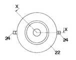
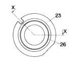
可動体20は、外周形状が半球状であるホーン22と、ホーン22の上面に被着される外周形状が半球状である蓋体23(図8、図9参照)とにより球状の外周形状に形成され、ホーン22と蓋体23とに囲まれる内部空間に超音波振動子21を収納して構成されている。図6および図7のように、ホーン22の下面には開口が形成され、超音波振動子はこの開口を通して超音波を授受する。また、ホーン22の両側面には軸部24が突設されており、この軸部24はボディ11の内周面に設けてある縦溝(図示せず)に上下に移動自在かつ軸部24の回りで回動自在となるように挿入され、可動体20の向きを変えることができるようになっている。超音波振動子21は、ホーン22や蓋体23との間で振動が伝達されることがないように円筒状のクッション体25の中に収納されている。ボディ11の下面にはボディ11の内外に貫通する円形の窓孔15が形成されており、窓孔15を通して可動体20の下部が露出し、この露出部位に可動体20の下面の開口が臨むように、可動体20の開口と窓孔15との寸法関係が設定されている。
【0020】
ボディ11の内部には、帯状の板金よりなり長手方向の中央部が上方に突出する形状に曲成された押さえ具30が固定されている。押さえ具30は、図10に示すように、長手方向の両端部に固定孔30aが形成され、固定孔30aを通してボディ11に螺合するねじ31によってボディ11に固定される。押さえ具30の中央部の下面側には支持体32が取り付けられる。支持体32は、図11に示すように、押さえ具30の中央部に穿孔した2個の引掛孔30aに挿通される2本の脚片32aと、押さえ具30の中央部に穿孔した透孔30bに挿通される1本の軸片32bとを備え、脚片32aの上端部には引掛孔30aの周部に係止されて支持体32の下方への抜け止めをする爪部32cが形成されている。押さえ具30と支持体32との間にはコイルばねよりなる押さえばね33が介装され、支持体32は押さえばね33によって押さえ具30に対して下向きに付勢されている。ここに、押さえばね33は、両脚片32aと軸片32bとの間に形成された溝内に下端部が保持され上端が押さえ具30に当接する。さらに、支持体32の下面にはゴムのような摩擦係数の大きい弾性体よりなる滑り止めとしてのOリング34が固着されている。
【0021】
上述のように、押さえ具30に対して支持体32の脚片32aを挿通し、かつ脚片32aの先端部に爪部32cを設けていることによって、組立時には押さえばね33のばね力が作用しても、図12(a)のように押さえ具30に支持体32を保持することができ、支持体32が押さえ具30から脱落するのを防止することができる。すなわち、組立作業が簡単になるのである。
【0022】
ボディ11の内部において、図12(b)に示すように、支持体32は可動体20の上面に当接するように配置されているのであって、可動体20は窓孔15の周部と支持体32との間で挟持され押さえばね33のばね力によって保持されることになる。したがって、ケース10の落下などによって可動体20に対して衝撃力が作用したときに、押さえばね33が圧縮されて図12(c)のように支持体32の軸片32bの基部周囲が押さえ具30の下面に当接するのであって、押さえばね33がコイルばねであって撓み量が大きいこととあいまって衝撃力を緩和する効果が大きくなる。衝撃力のような外力が解除されれば、押さえばね33のばね力によって可動体20は元の位置に復帰する。また、可動体20の蓋板23の上面にはホーン22の下面の開口と同軸上で形成された円環状の位置規制リブ26が突設されており、位置規制リブ26に囲まれる範囲内でのみ支持体32が可動体20に接触できるようになっている。すなわち、可動体20をボディ11に対して回動させたときには、図12(d)のように位置規制リブ26が支持体32に当接することによって可動体20の回動範囲が規制されるのであって、この回動範囲ではホーン22の下面の開口が窓孔15の周部にかぶることがないようにしてある。また、上述したように、支持体32の下面にはOリング34が固着されていてOリング34が可動体20に接触するから、可動体20とOリング34との摩擦力によって可動体20に小さい回転力が作用しただけでは可動体20が動かないようにしてある。
【0023】
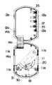
ところで、回路基板14a,14bは上下に重ねられるようにしてケース10の中に配置され、フラットケーブルまたは可撓性基板よりなる接続部14cを介して互いに接続されている。上側の回路基板14bの上面には負荷および電源を接続するための端子として速結端子35が3対実装されている(図5では2対のみを記載してある)。また、この回路基板14bには後述するスイッチ出力を発生するためのリレーRy1,Ry2(図13参照)が実装されている。速結端子35は周知のように、端子枠の中に錠ばねを配設し、カバー12の上面に設けた電線挿入口16から挿入された電線を錠ばねのばね力によって端子枠との間に挟持する構成のものであって、錠ばねは板ばねよりなり、電線接続時には電線に食い込んで抜け止めをするように形成されている。また、錠ばねによる電線の接続状態を解除するために解除釦17を備え、解除釦17はドライバのような工具で操作できるように一部がカバー12の上面から露出する。また、電線挿入口16は、カバー12に被嵌される端子カバー40によって覆われる。
【0024】
下側の回路基板14aには可動体20より引き出された超音波振動子21からのリード線18が接続される。また、回路基板14aには発光ダイオードよりなる動作表示灯LDと、周囲照度を検出する照度センサPDとが実装されており、動作表示灯LDの発光面と照度センサPDの受光面とは、ボディ11に装着してある略L形のプリズム19に設けた入射面および出射面に対向し、このプリズム19を介して、動作表示灯LDからの発光表示の光をケース10の外部に導出したり、ケース10の外部からの光を照度センサPDに導入したりすることができるようになっている。
【0025】
フランジ13は、両端部に埋込ボックスや天井材への直付けのための2個の取付孔41が穿設され、また両側部の上面にフランジ13との間で天井材を挟持するための挟み具42を着脱自在に装着する装着部が設けられている。さらに、フランジ13の下面には化粧プレート50が着脱自在に覆着される。
挟み具42は、天井材に穿孔した取付孔にケース10の上部を挿入し、天井材の下面にフランジ13の上面を当接させた形でケース10を天井材に固定するものであって、一側面が開口した縦長の金具本体44と、金具本体44の底部を下方から貫通し先端を金具本体44の天井部に回転自在に保持させたねじ体45と、ねじ体45のねじ部をねじ孔に螺入させた金属製の挟持体46とで構成されている。
【0026】
この挟み具42を用いてケース10を天井に取り付けるには、まず、フランジ13に穿孔されただるま孔47の丸孔部にねじ体45の頭部をフランジ13の上面側から嵌め込んでフランジ13の下面側に露出させる。このとき同時に、だるま孔47の両側に並行してフランジ13の上面に設けてある固定溝48に、金具本体44の下面両側に設けた固定片49を嵌め込む。この状態で固定片49を固定溝48内でスライドさせながら、金具本体44をフランジ13の中央方向へ移動させると、金具本体44の下面より外部に露出しているねじ体45の頭部がだるま孔47の長孔部に案内され、だるま孔47の周部が金具本体44の下面とねじ体45の頭部との間に挟まれる。
【0027】
次に、ねじ体45の反締付方向の金具本体44の片側側壁に形成してある切欠44aに挟持体46を挿入したケース10の上部を天井材に穿孔した取付孔に挿入する。このとき、挟持体46は金具本体44に対してボディ11およびカバー12の側面に沿う方向に突出しているから、取付孔に引っ掛かることなく挿入することができる。その後、フランジ13の上面を天井材の下面に当接させた状態でねじ体45をドライバ等で締め付け方向に回転させると、ねじ体45の回転により挟持体46は切欠44aより出て、金具本体44の他方の側壁に側端が当たることになる。このとき、挟持体46の先端部は取付孔の投影範囲より外側に出て天井材の上方に位置する。したがって、挟持体46はねじ体45の締め付けに伴ってフランジ13に近付く向きに移動し、挟持体46の先端部が天井材の上面に当たると、挟持体16とフランジ13との間に天井材が挟持され、天井材にケース10を固定することができるのである。
【0028】
化粧プレート50はフランジ13の周縁を囲む周壁50aを有し、フランジ13の周縁に突設してある係止爪13aに係合する係止溝を周壁50aの内周面に形成してあり、化粧プレート50の弾性を利用して係止爪を係止溝に着脱自在に係合させることができるようになっている。化粧プレート50の中心部には、ボディ11の窓孔15に対応した丸孔が形成されており、この丸孔を通して可動体20とともにプリズム19の端面が露出する。
【0029】
ところで、回路基板14a,14bには、図13に示すような回路が実装されている。すなわち、超音波振動子21より超音波を送出するとともに検知エリアから超音波振動子21に入射した超音波を受信して、検知エリア内での人の存否を判定する人体検知判定部61を有する。
人体検知判定部61は、たとえば送波した超音波の周波数に対して受波した超音波の周波数に偏移が生じたときに移動物体が検知エリアに存在すると判断するドップラ方式のものを用いることができる。すなわち、ドップラ方式としては一定周波数の超音波を送波し、受波信号については送波周波数と同じ周波数で位相の異なる2種の信号と混合することによって、位相の異なる2種のドップラ信号を生成し、周波数偏移の方向を両ドップラ信号の位相の進み遅れに置き換えることによって、移動物体を検出する方式が知られている。このような方式によって検知エリア内の人の存否を検出し、人体検知判定部61では人の存在を検出すると出力(たとえばHレベル)を発生するのである。また、ドップラ方式を採用したことによって、周囲の静止している物を検出することがないから、距離の測定による方式に比較して設置時の調整が簡単になる。
【0030】
一方、照度センサPDの出力は照度判定部62に入力され、基準照度と比較される。照度判定部62では、たとえば周囲照度が基準照度よりも低いとき(つまり、周囲が暗いとき)に出力(たとえばHレベル)を発生する。
人体検知判定部61と照度判定部62との出力は論理積回路63に入力され、周囲照度が基準照度よりも低いときに人が検出されると、論理積回路63からオン出力(Hレベル)が出力されるようになっている。この論理積回路63のオン出力によってスイッチ出力あるリレーRy1がオンになるのである。また、人体検知判定部61の出力は遅延動作制御部64を介してスイッチ出力であるリレーRy2のオン・オフを制御する。
【0031】
遅延動作制御部64は、動作選択手段である動作タイミング選択部65での設定に応じて、人体検知判定部61によって人が検出されたときにオン出力(Hレベル)を発生する第1の選択状態と、人体検知判定部61によって人が検出されている状態から検出されない状態に変化した後にオン出力(Hレベル)を発生する第2の選択状態とが択一的に選択されるようになっている。また、遅延動作制御部64では、人体検知判定部61で人が検知された状態から検知されない状態に変化した時点の後に、時間設定手段である遅延時間設定部66で設定された遅延時間だけオン出力を継続させるようになっている。要するに、第1の選択状態では人が検出されると同時にリレーRy2がオンになり、人の存在が検出されなくなってから遅延時間が経過した後にリレーRy2がオフになる。また、第2の選択状態では、人が検出されたときにはリレーRy2はオフであって、人が検出されなくなってから遅延時間が経過するまでの間にリレーRy2がオンになるのである。
【0032】
リレーRy1は商用電源ACを接続する電源端子T1と、負荷としての照明Lを接続する負荷端子T21との間に挿入され、リレーRy2は電源端子T1と換気線Fを接続する負荷端子T22との間に挿入される。したがって、リレーRy1がオンになれば照明Lが点灯し、リレーRy2がオンになれば換気扇Fが作動する。また、人体検知判定部61、照度判定部62、論理積回路63、遅延動作制御部64はマイクロコンピュータなどによって実現され、商用電源ACから定電圧電源回路である電源回路67を通して給電される。さらに、人体検知判定部61の出力は動作表示灯LDにも出力され、人体の存否に応じて動作表示灯LDが点灯・消灯するようになっている。動作タイミング選択部65、遅延時間設定部66などの操作部はフランジ13の下面側に露出し、化粧カバー50を外すことによって操作できるようにしてある。
【0033】
次に動作について説明する。いま、動作タイミング選択部65によって、人の検知からオン出力が発生する第1の選択状態が選択されているものとする。この状態において、周囲が暗いときに人がトイレに入ると照明Lが自動的に点灯する。また、換気扇Fは自動的に作動して室内の空気を外部に排出する。人が退出したときには、照明Lはただちに消灯するが、換気扇Fは遅延時間だけ継続して作動する。一方、周囲が明るく周囲照度が基準照度よりも高いときには、人が入っても照明Lは点灯しないが、換気扇Fは作動することになる。また、人が退出すれば遅延時間の経過後に換気扇Fは自動的に停止する。
【0034】
次に、動作タイミング選択部65によって、第2の選択状態が選択されているものとすると、照明Lについては第1の選択状態と同じように点灯・消灯することになる。一方、換気扇Fについては、人がトイレに入っている間は作動せず、人が退出した後に遅延時間が経過するまで作動することになる。このような動作では冬季などで寒いときに、換気扇Fの作動で冷えるのを防止することが可能になる。
【0035】
上記実施例では、超音波振動子21を用いて人の存否を検出しているが、焦電センサを用いて人体から放射される熱線を検出することによって人の存否を検出するようにしてもよい。この場合には、ホーン22に代えて受光レンズを用いるとよい。
【0036】
【発明の効果】
請求項1の発明は、ケース内に固定された押さえ具に対してコイルばねである押さえばねによって可動体に向かって付勢されている支持体と、ケースの前面に開口した窓孔の周部との間で可動体を挟持するのであり、コイルばねは体積に対する撓み量を比較的大きくとることができるので、ケース内の制限された空間であっても十分に撓ませることができ、落下衝撃などが可動体に作用した場合でも衝撃力を緩和することができ、可動体や人体検知センサなどの破損、変形、故障などの発生確率が低減することができるという利点がある。しかも、コイルばねは寸法に多少のばらつきがあってもばね力に対する影響が少ないから、部品の精度管理が容易になり、結果的にコストの低減につながるという効果がある。加えて、支持体は押さえ具に挿通されかつ先端部に抜け止め用の爪部を設けた脚片を備えているから、押さえばねのばね力が作用しても爪部によって支持体が押さえ具に係止され、組立時における支持体の脱落を防止することができて組立が容易になるという利点がある。
【0037】
請求項2の発明は、支持体における可動体との接触面にリング状の滑り止めを設けているから、可動体は支持体に対して位置がずれにくいのであって、ケースや可動体の表面を清掃する際に可動体に軽く触れたり、外部振動が作用したとしても、可動体が不用意に回転することがなく、設定した検知エリアがずれるのを防止することができるという利点がある。
【0038】
請求項3の発明は、可動体の外周面の一部に形成した環状の位置規制リブによって支持体と可動体との接触範囲が規制されるから、可動体の回動範囲が規制されるのであって、人体検知センサの検知エリアがケースの窓孔の周部に重ならないような範囲で可動体を回動させることが可能になるという利点を有する。
請求項4の発明は、照度センサを付加することによって周囲照度を検出しているので、周囲照度と既定照度との高低と人体検知センサにより検出した人の存否との論理積を用いることで、人体検知センサによる検出結果を周囲照度に応じて採用するか否かが決まるのである。たとえば、人の存否に応じて照明を自動点滅させるとすれば、周囲が明るいときには自動点滅が不要であるから、周囲が暗いときにのみ人体検知センサによる検出結果を採用するという制御が行なえるという効果がある。また、周囲照度に応じた第1のスイッチ出力と、周囲照度とは無関係な第2のスイッチ出力とを設けていることによって、たとえば、トイレにおいて照明と換気扇とを自動的にオン・オフさせる場合であって、照明については周囲が明るいときにはオフにしておき、換気扇については人が出入りするたびにオンにするのであれば、照明を第1のスイッチ出力によって制御し、換気扇を第2のスイッチ出力によって制御することができ、結果的に、人体検知式自動スイッチを1箇所に施工するだけで、照明と換気扇とを所望した通りに制御することが可能になるという利点がある。
【0039】
請求項5の発明は、人体の存在を検知すると第2のスイッチ出力をオン出力とし人体の存在が検知されなくなってから所定の遅延時間が経過した後にオン出力を停止する第1の選択状態が設定できるので、トイレなどで換気線を動作させる際に人が入室すれば換気扇が自動的に作動し、人の退出後の所定の遅延時間まで継続して換気扇を作動させることができるという利点がある。また、人体の存在が検知されなくなってから所定の遅延時間が経過するまでの期間のみにオン出力を発生する第2の選択状態が設定できるから、冬季などにおいて在室中に換気扇を作動させると寒さを感じるようなときには、退出後にのみ換気扇を作動させることができるという利点がある。このように、第1の選択状態と第2の選択状態とを選択する動作選択手段を備えていることによって、使用環境に応じた設定が可能になり使い勝手がよいのである。
【0040】
請求項6の発明は、遅延時間を設定する時間設定手段を設けているので、使用条件に応じた遅延時間の設定が可能になり、使い勝手がよいという利点を有するのである。
請求項7の発明および請求項8の発明は、望ましい実施態様であって、人体検知センサとして超音波の送受波を利用したものを採用すれば、人が検知エリア内に存在する間は常に出力を得ることができ、検知エリア内での人の滞在時間が長いような場合に有効であり、一方、焦電センサを用いたものでは、不要反射等の影響を受けることなく検知エリアを所望範囲に設定するのが容易になるという利点がある。
【図面の簡単な説明】
【図1】実施例を示し、(a)は正面図、(b)は要部の一部破断した分解側面図である。
【図2】実施例の側面図である。
【図3】実施例の一部破断した平面図である。
【図4】実施例の化粧カバーを外した下面図である。
【図5】実施例のボディとカバーとを展開した状態の平面図である。
【図6】実施例に用いるホーンを示す側面図である。
【図7】実施例に用いるホーンを示す図6のX−X線断面図である。
【図8】実施例に用いる蓋体を示す側面図である。
【図9】実施例に用いる蓋体を示す図8のX−X線断面図である。
【図10】実施例に用いる押さえ具を示し、(a)は平面図、(b)は断面図である。
【図11】実施例に用いる支持体を示し、(a)は平面図、(b)は同図(a)のX−X線断面図である。
【図12】実施例の要部の動作説明図である。
【図13】実施例の回路を示すブロック図である。
【符号の説明】
10 ケース
15 窓孔
20 可動体
21 超音波振動子
26 位置規制リブ
30 押さえ具
32a 脚片
32c 爪部
32 支持体
33 押さえばね
34 Oリング
61 人体検知判定部
62 照度判定部
63 論理積回路
64 遅延動作制御部
65 動作タイミング選択部
66 遅延時間設定部
F 換気扇
L 照明
PD 照度センサ
Ry1リレー
Ry2リレー[0001]
[Industrial applications]
The present invention relates to a human body detection type automatic switch mainly used in a room such as a toilet and automatically turning on and off a lighting and a ventilation fan according to the presence or absence of a person in the room.
[0002]
[Prior art]
Conventionally, a human body detection type automatic switch that automatically turns on and off lighting and ventilation lines by detecting the entry, occupancy, and exit of a person, detects the presence or absence of a person by transmitting and receiving ultrasonic waves, There is known a device provided with a human body detection sensor that detects the presence or absence of a person by detecting a heat ray radiated from the device. By the way, in this type of human body detection type automatic switch, malfunction is likely to occur when the detection area is set to the whole area of the room, so the detection area is limited to a part of the room and fixed to the ceiling etc. At present, it is possible to change the direction of the human body detection sensor with respect to the case to suppress occurrence of malfunction.
[0003]
That is, by providing a spherical movable body rotatably housed in the case so that a part thereof is exposed from the case, and storing the human body detection sensor in this movable body, the direction of the detection area of the human body detection sensor can be changed. That is, it can be set in a desired direction. The movable body is sandwiched between a window hole opened on the front surface of the case and a holding member formed of a leaf spring fixed in the case by a spring force of the holding member. Therefore, if the movable body is rotated while being pressed from outside the case toward the holding member, the direction of the human body detection sensor can be changed.
[0004]
[Problems to be solved by the invention]
By the way, in the above configuration, the spring force for holding the movable body is the spring force of the leaf spring, and it is difficult to secure a sufficient amount of deflection in a limited space in the case. Therefore, when an impact force acts on the movable body at the time of dropping, etc., the holding force cannot sufficiently reduce the impact force acting on the movable body. There is a problem that the human body detection sensor in the body breaks down.
[0005]
In addition, the retainer is relatively small, and even if the thickness or the size of the bending position is slightly changed, the holding force of the movable body will change, and it is necessary to suppress the variation in operation feeling for each product. Therefore, it is necessary to increase the accuracy of managing the dimensions of parts, which is a factor of high cost.
SUMMARY OF THE INVENTION An object of the present invention is to solve the above-described problem, and it is possible to use a coil spring capable of securing a relatively large amount of deflection in a limited space, thereby acting on a movable body at the time of dropping or the like. By adopting a configuration that reduces the impact force and suppresses the deformation and breakage of parts and the variation in operation feeling for each product, human body detection that facilitates precision control of part dimensions and reduces cost It is intended to provide a type automatic switch.
[0006]
[Means for Solving the Problems]
In order to achieve the above object, a first aspect of the present invention provides a case that is fixed to a construction surface with a rear portion inserted into a mounting hole formed in the construction surface, and a case that is housed in the case and is located in front of the case. A human body detection sensor that detects the presence or absence of a person in a detection area set in the range, a switch processing unit that generates a switch output for load control based on the output of the human body detection sensor, and a human body detection sensor that is formed in a spherical shape The movable body which is rotatably inserted into the case in a form in which a part is exposed from the window hole formed in the front surface of the case and the movable body fixed in the case and the peripheral portion of the window hole And a holding device that is disposed between the movable body and the holding device, the holding device being provided opposite to the opening surface of the window hole.Each of the two hook holesPenetratedAnd hooked around the hook holeClaws for retainingAt the tipFormedHaving two leg pieces and one shaft piece inserted through a through hole formed in the holding member.It is characterized by comprising a supporting member, and a pressing spring formed of a coil spring inserted between the holding member and the supporting member to urge the supporting member toward the movable member.
[0007]
According to a second aspect of the present invention, in the first aspect of the present invention, the support is in contact with the movable body.Phosphorus on the surfaceIt is characterized in that it is provided with an anti-slipping member.
According to a third aspect of the present invention, in the first aspect of the present invention, an annular position regulating rib is protruded from a part of the outer peripheral surface of the movable body, and the support contacts the movable body inside the position regulating rib and supports the movable body. Is characterized in that the range of rotation of the movable body is regulated by the position where it contacts the position regulating rib.
[0008]
According to a fourth aspect of the present invention, in the first aspect of the present invention, there is provided an illuminance sensor for detecting the ambient illuminance, and the switch processing unit detects the level of the ambient illuminance detected by the illuminance sensor and the predetermined illuminance and detects the level by the human body detection sensor. A first switch output based on a logical product of the presence or absence of a person and a second switch output based on the presence or absence of a person detected by a human body detection sensor regardless of ambient illuminance are generated.
[0009]
According to a fifth aspect of the present invention, in the fourth aspect, when the presence of a human body is detected, the second switch output is turned on, and the on output is stopped after a predetermined delay time has elapsed after the presence of the human body is no longer detected. Operation selection means for selecting a first selection state in which the ON output is generated only during a period from when the presence of the human body is no longer detected until a predetermined delay time elapses. Features.
[0010]
A sixth aspect of the present invention is characterized in that, in the fifth aspect of the present invention, a time setting means for setting a delay time is provided.
According to a seventh aspect of the present invention, in the first aspect, the human body detection sensor is an ultrasonic sensor that detects the presence or absence of a person by transmitting an ultrasonic wave and detecting a state change of a reflected wave. I do.
[0011]
The invention according to claim 8 is the invention according to claim 1, wherein the human body detection sensor is a pyroelectric sensor that detects the presence or absence of a person by detecting a heat ray radiated from the human body.
[0012]
[Action]
According to the first aspect of the present invention, the supporting member urged toward the movable body by the pressing spring, which is a coil spring, against the pressing member fixed in the case, and the window hole opened in the front surface of the case. The movable body is clamped between the peripheral part. Coil springs can have a relatively large amount of deflection relative to volume, so they can be sufficiently bent even in the limited space inside the case, and can provide an impact force even when a drop impact acts on the movable body. The probability of occurrence of breakage, deformation, failure, and the like of the movable body and the human body detection sensor can be reduced. In addition, the coil spring has little influence on the spring force even if there is a slight variation in the dimensions, so that the precision control of the parts is facilitated, and as a result, the cost is reduced. In addition, since the support is provided with a leg which is inserted into the holding member and has a claw portion for retaining at the distal end portion, the supporting member is held by the claw portion even when the spring force of the holding spring acts. To prevent the support from dropping off during assembly, which facilitates assembly.
[0013]
According to the invention of
[0014]
According to the third aspect of the present invention, since the contact range between the support and the movable body is regulated by the annular position regulating rib formed on a part of the outer peripheral surface of the movable body, the rotation range of the movable body is regulated. Therefore, it is possible to rotate the movable body within a range where the detection area of the human body detection sensor does not overlap the periphery of the window of the case.
According to the invention of claim 4, the ambient illuminance is detected by adding the illuminance sensor, and the logical product of the level of the ambient illuminance and the predetermined illuminance and the presence or absence of a person detected by the human body detection sensor is calculated. By using, it is determined whether or not to adopt the detection result by the human body detection sensor according to the ambient illuminance. For example, if the lighting is automatically blinked according to the presence or absence of a person, automatic blinking is unnecessary when the surroundings are bright, so that control can be performed such that the detection result of the human body detection sensor is adopted only when the surroundings are dark. is there. Further, by providing the first switch output corresponding to the ambient illuminance and the second switch output irrelevant to the ambient illuminance, for example, when the lighting and the ventilation fan are automatically turned on / off in a toilet If the lighting is to be turned off when the surroundings are bright and the ventilation fan is turned on each time a person enters or exits, the lighting is controlled by the first switch output, and the ventilation fan is switched to the second switch output. Can be controlled by As a result, the lighting and the ventilation fan can be controlled as desired only by installing the human body detection type automatic switch at one place.
[0015]
According to the fifth aspect of the present invention, when the presence of a human body is detected, the second switch output is set to the ON output, and the ON output is stopped after a predetermined delay time has elapsed after the detection of the presence of the human body is stopped. Since the state can be set, if a person enters when operating the ventilation line in the toilet etc., the ventilation fan will automatically operate, and the ventilation fan can be operated continuously until the predetermined delay time after the person leaves is there. In addition, since the second selection state in which the ON output is generated only during a period from when the presence of the human body is no longer detected until a predetermined delay time elapses can be set, when the ventilation fan is operated while in the room in winter or the like, When you feel cold, you can turn on the ventilation fan only after you leave. As described above, the provision of the operation selecting means for selecting the first selection state and the second selection state makes it possible to make settings according to the use environment, thereby improving usability.
[0016]
According to the invention of claim 6, since the time setting means for setting the delay time is provided, it is possible to set the delay time according to the use condition, which is convenient.
The invention according to claim 7 and the invention according to claim 8 are preferable embodiments. If a sensor utilizing transmission / reception of ultrasonic waves is adopted as a human body detection sensor, output is always performed while a person is present in the detection area. Is effective when a person stays in the detection area for a long time. On the other hand, in the case of using a pyroelectric sensor, the detection area can be set to a desired range without being affected by unnecessary reflection or the like. To be easily set.
[0017]
【Example】
In the present embodiment, as shown in FIG. 13, an example is shown in which a human body detection type automatic switch is used to automatically turn on and off the lighting L and the ventilation line F in response to a person entering and exiting the toilet. Further, a human body detection sensor that transmits and receives ultrasonic waves is used.
[0018]
As shown in FIGS. 1 to 5, the
[0019]
The
[0020]
A holding
[0021]
As described above, by inserting the
[0022]
As shown in FIG. 12B, the
[0023]
Meanwhile, the
[0024]
The
[0025]
The
The clip 42 fixes the
[0026]
In order to attach the
[0027]
Next, the upper part of the
[0028]
The
[0029]
Incidentally, a circuit as shown in FIG. 13 is mounted on the
The human body
[0030]
On the other hand, the output of the illuminance sensor PD is input to the
Outputs of the human body
[0031]
The delay
[0032]
Relay Ry1Is a power supply terminal T for connecting a commercial power supply AC.1And a load terminal T for connecting a lighting L as a load.21Between the relay Ry2Is the power supply terminal T1Terminal T connecting the ventilation line F to the22Inserted between Therefore, the relay Ry1Is turned on, the illumination L is turned on and the relay Ry2Is turned on, the ventilation fan F operates. The human body
[0033]
Next, the operation will be described. Now, it is assumed that the operation
[0034]
Next, assuming that the second selection state is selected by the operation
[0035]
In the above embodiment, the presence or absence of a person is detected using the
[0036]
【The invention's effect】
According to the first aspect of the present invention, there is provided a supporting member which is urged toward a movable body by a pressing spring which is a coil spring with respect to a pressing member fixed in a case, and a peripheral portion of a window hole opened in a front surface of the case. Since the movable body is sandwiched between the coil spring and the coil spring, the amount of deflection with respect to the volume can be relatively large, so that the coil spring can sufficiently bend even in a limited space in the case, and the drop impact Even when such factors act on the movable body, the impact force can be reduced, and there is an advantage that the probability of occurrence of breakage, deformation, failure, and the like of the movable body and the human body detection sensor can be reduced. In addition, the coil spring has little effect on the spring force even if there is a slight variation in the dimensions, so that the precision control of the parts is facilitated, and as a result, the cost is reduced. In addition, since the support is provided with a leg which is inserted into the holding member and has a claw portion for retaining at the tip portion, the supporting member is held by the holding member even when the spring force of the holding spring acts. To prevent the support from falling off at the time of assembling, thereby facilitating assembling.
[0037]
According to a second aspect of the present invention, the contact between the support and the movable body is provided.Phosphorus on the surfaceThe movable body is unlikely to be misaligned with respect to the support due to the provision of a slip-shaped anti-slip.When cleaning the case and the surface of the movable body, the movable body was lightly touched or external vibration was applied. However, there is an advantage that the movable body does not rotate carelessly and the set detection area can be prevented from shifting.
[0038]
According to the third aspect of the invention, since the contact range between the support and the movable body is regulated by the annular position regulating rib formed on a part of the outer peripheral surface of the movable body, the rotation range of the movable body is regulated. Therefore, there is an advantage that the movable body can be rotated within a range in which the detection area of the human body detection sensor does not overlap the periphery of the window of the case.
The invention according to claim 4 detects the ambient illuminance by adding an illuminance sensor. Therefore, by using the logical product of the level of the ambient illuminance and the predetermined illuminance and the presence or absence of a person detected by the human body detection sensor, It is decided whether or not to adopt the detection result by the human body detection sensor according to the surrounding illuminance. For example, if the lighting is automatically blinked according to the presence or absence of a person, the automatic blinking is unnecessary when the surroundings are bright, so that control can be performed such that the detection result by the human body detection sensor is adopted only when the surroundings are dark. effective. Further, by providing the first switch output corresponding to the ambient illuminance and the second switch output irrelevant to the ambient illuminance, for example, when the lighting and the ventilation fan are automatically turned on / off in a toilet If the lighting is to be turned off when the surroundings are bright and the ventilation fan is turned on each time a person enters or exits, the lighting is controlled by the first switch output, and the ventilation fan is switched to the second switch output. As a result, there is an advantage that the lighting and the ventilation fan can be controlled as desired only by installing the human body detection type automatic switch at one place.
[0039]
According to a fifth aspect of the present invention, when the presence of a human body is detected, the second switch output is turned on and the first selection state in which the on output is stopped after a predetermined delay time has elapsed after the presence of the human body is no longer detected. Since it can be set, when a person enters the room when operating the ventilation line in the toilet etc., the ventilation fan is automatically activated, and the advantage that the ventilation fan can be operated continuously until the predetermined delay time after the person leaves the room. is there. In addition, since the second selection state in which the ON output is generated only during a period from when the presence of the human body is no longer detected until a predetermined delay time elapses can be set, when the ventilation fan is operated while in the room in winter or the like, When feeling cold, there is an advantage that the ventilation fan can be operated only after leaving. As described above, the provision of the operation selecting means for selecting the first selection state and the second selection state makes it possible to make settings according to the use environment, thereby improving usability.
[0040]
According to the sixth aspect of the present invention, since the time setting means for setting the delay time is provided, it is possible to set the delay time according to the use condition, and there is an advantage that the usability is good.
The invention according to claim 7 and the invention according to claim 8 are preferable embodiments. If a sensor utilizing transmission / reception of ultrasonic waves is adopted as a human body detection sensor, output is always performed while a person is present in the detection area. Is effective when a person stays in the detection area for a long time. On the other hand, in the case of using a pyroelectric sensor, the detection area can be set to a desired range without being affected by unnecessary reflection or the like. There is an advantage that it is easy to set to.
[Brief description of the drawings]
FIGS. 1A and 1B show an embodiment, wherein FIG. 1A is a front view, and FIG.
FIG. 2 is a side view of the embodiment.
FIG. 3 is a partially broken plan view of the embodiment.
FIG. 4 is a bottom view of the embodiment with the decorative cover removed.
FIG. 5 is a plan view showing a state where a body and a cover of the embodiment are expanded.
FIG. 6 is a side view showing a horn used in the embodiment.
FIG. 7 is a sectional view taken along line XX of FIG. 6, showing a horn used in the embodiment.
FIG. 8 is a side view showing a lid used in the embodiment.
FIG. 9 is a sectional view taken along line XX of FIG. 8 showing a lid used in the example.
FIGS. 10A and 10B show holding members used in the embodiment, in which FIG. 10A is a plan view and FIG. 10B is a sectional view.
FIGS. 11A and 11B show a support used in the example, in which FIG. 11A is a plan view, and FIG. 11B is a sectional view taken along line XX of FIG.
FIG. 12 is an operation explanatory view of a main part of the embodiment.
FIG. 13 is a block diagram illustrating a circuit according to an embodiment.
[Explanation of symbols]
10 cases
15 windows
20 movable bodies
21 Ultrasonic transducer
26 Position control rib
30 Holder
32a leg piece
32c claw
32 support
33 Holding spring
34 O-ring
61 Human body detection judgment unit
62 Illumination judgment unit
63 AND circuit
64 delay operation control unit
65 Operation timing selector
66 Delay time setting section
F ventilation fan
L lighting
PD illuminance sensor
Ry1relay
Ry2relay
Claims (8)
Translated fromJapanesePriority Applications (1)
| Application Number | Priority Date | Filing Date | Title |
|---|---|---|---|
| JP12438293AJP3579907B2 (en) | 1993-05-26 | 1993-05-26 | Human body detection type automatic switch |
Applications Claiming Priority (1)
| Application Number | Priority Date | Filing Date | Title |
|---|---|---|---|
| JP12438293AJP3579907B2 (en) | 1993-05-26 | 1993-05-26 | Human body detection type automatic switch |
Publications (2)
| Publication Number | Publication Date |
|---|---|
| JPH06333472A JPH06333472A (en) | 1994-12-02 |
| JP3579907B2true JP3579907B2 (en) | 2004-10-20 |
Family
ID=14884029
Family Applications (1)
| Application Number | Title | Priority Date | Filing Date |
|---|---|---|---|
| JP12438293AExpired - LifetimeJP3579907B2 (en) | 1993-05-26 | 1993-05-26 | Human body detection type automatic switch |
Country Status (1)
| Country | Link |
|---|---|
| JP (1) | JP3579907B2 (en) |
- 1993
- 1993-05-26JPJP12438293Apatent/JP3579907B2/ennot_activeExpired - Lifetime
Also Published As
| Publication number | Publication date |
|---|---|
| JPH06333472A (en) | 1994-12-02 |
Similar Documents
| Publication | Publication Date | Title |
|---|---|---|
| JP4640239B2 (en) | Automatic switch with hot wire sensor | |
| US20130342029A1 (en) | Controller for use with a mechanical switch | |
| US5510791A (en) | Remote control unit for installation in vehicle | |
| US5113318A (en) | Thermostat light | |
| JP3579907B2 (en) | Human body detection type automatic switch | |
| JP3591389B2 (en) | Hot wire automatic switch for toilet | |
| US7095332B2 (en) | Alarm device | |
| JP3232154B2 (en) | Ceiling mounted heat ray sensing type automatic switch | |
| JP3473375B2 (en) | Hot wire automatic switch | |
| JP2000131136A (en) | Hot wire type human sensor | |
| JP3381942B2 (en) | Heat ray sensing type load control system | |
| JP3899529B2 (en) | lighting equipment | |
| JP3860633B2 (en) | Heat ray-sensitive automatic switch | |
| JP2863232B2 (en) | Heat ray sensing type human body detection switch | |
| JP3467928B2 (en) | Load control device with heat ray sensor | |
| JP2008186310A (en) | Fire alarm | |
| JP2000048689A (en) | Heat ray sensing type automatic switch | |
| JP2000011265A (en) | Automatic switch with heat ray sensor | |
| JP3363174B2 (en) | Hot wire automatic switch | |
| JP2854827B2 (en) | Controller for automatic switch to detect heat rays | |
| JP2863230B2 (en) | Heat ray sensing type human body detection switch | |
| JPH1163596A (en) | Heat ray sensing type automatic switch | |
| JPH02242192A (en) | Heat sensitive switch | |
| JP2003132771A (en) | Heat ray sensible switch | |
| JP2772285B2 (en) | Heat ray sensing type human body detection switch |
Legal Events
| Date | Code | Title | Description |
|---|---|---|---|
| TRDD | Decision of grant or rejection written | ||
| A01 | Written decision to grant a patent or to grant a registration (utility model) | Free format text:JAPANESE INTERMEDIATE CODE: A01 Effective date:20040629 | |
| A61 | First payment of annual fees (during grant procedure) | Free format text:JAPANESE INTERMEDIATE CODE: A61 Effective date:20040712 | |
| FPAY | Renewal fee payment (event date is renewal date of database) | Free format text:PAYMENT UNTIL: 20070730 Year of fee payment:3 | |
| FPAY | Renewal fee payment (event date is renewal date of database) | Free format text:PAYMENT UNTIL: 20080730 Year of fee payment:4 | |
| FPAY | Renewal fee payment (event date is renewal date of database) | Free format text:PAYMENT UNTIL: 20090730 Year of fee payment:5 | |
| FPAY | Renewal fee payment (event date is renewal date of database) | Free format text:PAYMENT UNTIL: 20090730 Year of fee payment:5 | |
| S533 | Written request for registration of change of name | Free format text:JAPANESE INTERMEDIATE CODE: R313533 | |
| FPAY | Renewal fee payment (event date is renewal date of database) | Free format text:PAYMENT UNTIL: 20090730 Year of fee payment:5 | |
| R350 | Written notification of registration of transfer | Free format text:JAPANESE INTERMEDIATE CODE: R350 | |
| FPAY | Renewal fee payment (event date is renewal date of database) | Free format text:PAYMENT UNTIL: 20090730 Year of fee payment:5 | |
| FPAY | Renewal fee payment (event date is renewal date of database) | Free format text:PAYMENT UNTIL: 20100730 Year of fee payment:6 | |
| FPAY | Renewal fee payment (event date is renewal date of database) | Free format text:PAYMENT UNTIL: 20100730 Year of fee payment:6 | |
| FPAY | Renewal fee payment (event date is renewal date of database) | Free format text:PAYMENT UNTIL: 20110730 Year of fee payment:7 | |
| FPAY | Renewal fee payment (event date is renewal date of database) | Free format text:PAYMENT UNTIL: 20120730 Year of fee payment:8 | |
| FPAY | Renewal fee payment (event date is renewal date of database) | Free format text:PAYMENT UNTIL: 20120730 Year of fee payment:8 | |
| FPAY | Renewal fee payment (event date is renewal date of database) | Free format text:PAYMENT UNTIL: 20130730 Year of fee payment:9 | |
| EXPY | Cancellation because of completion of term |