JP3578215B2 - Apparatus and method for detoxifying toxic substances - Google Patents
Apparatus and method for detoxifying toxic substancesDownload PDFInfo
- Publication number
- JP3578215B2 JP3578215B2JP50719294AJP50719294AJP3578215B2JP 3578215 B2JP3578215 B2JP 3578215B2JP 50719294 AJP50719294 AJP 50719294AJP 50719294 AJP50719294 AJP 50719294AJP 3578215 B2JP3578215 B2JP 3578215B2
- Authority
- JP
- Japan
- Prior art keywords
- plenum
- processing system
- volatile organic
- electron beam
- reaction
- Prior art date
- Legal status (The legal status is an assumption and is not a legal conclusion. Google has not performed a legal analysis and makes no representation as to the accuracy of the status listed.)
- Expired - Fee Related
Links
- 238000000034methodMethods0.000titleclaimsdescription40
- 239000003440toxic substanceSubstances0.000titledescription2
- 231100000614poisonToxicity0.000title1
- 238000010894electron beam technologyMethods0.000claimsdescription61
- 238000006243chemical reactionMethods0.000claimsdescription41
- 239000012855volatile organic compoundSubstances0.000claimsdescription41
- 238000012545processingMethods0.000claimsdescription33
- 239000000126substanceSubstances0.000claimsdescription27
- 230000003993interactionEffects0.000claimsdescription12
- 239000000463materialSubstances0.000claimsdescription12
- 239000000543intermediateSubstances0.000claimsdescription5
- 230000008646thermal stressEffects0.000claimsdescription3
- VEXZGXHMUGYJMC-UHFFFAOYSA-MChloride anionChemical compound[Cl-]VEXZGXHMUGYJMC-UHFFFAOYSA-M0.000claimsdescription2
- 239000011358absorbing materialSubstances0.000claimsdescription2
- 239000002253acidSubstances0.000claimsdescription2
- 239000002516radical scavengerSubstances0.000claimsdescription2
- 239000013067intermediate productSubstances0.000claims2
- 239000003054catalystSubstances0.000claims1
- 150000001805chlorine compoundsChemical class0.000claims1
- 230000007613environmental effectEffects0.000claims1
- 229920001903high density polyethylenePolymers0.000claims1
- 229930195733hydrocarbonNatural products0.000claims1
- 150000002430hydrocarbonsChemical class0.000claims1
- 238000012544monitoring processMethods0.000claims1
- 150000002894organic compoundsChemical class0.000claims1
- 239000000047productSubstances0.000claims1
- 239000012048reactive intermediateSubstances0.000claims1
- 239000007789gasSubstances0.000description33
- MWUXSHHQAYIFBG-UHFFFAOYSA-Nnitrogen oxideInorganic materialsO=[N]MWUXSHHQAYIFBG-UHFFFAOYSA-N0.000description18
- 230000008569processEffects0.000description10
- 238000010521absorption reactionMethods0.000description9
- 239000002689soilSubstances0.000description9
- 229910052815sulfur oxideInorganic materials0.000description7
- 230000002588toxic effectEffects0.000description7
- 238000013461designMethods0.000description6
- 238000001784detoxificationMethods0.000description6
- IJGRMHOSHXDMSA-UHFFFAOYSA-NAtomic nitrogenChemical compoundN#NIJGRMHOSHXDMSA-UHFFFAOYSA-N0.000description5
- 238000000605extractionMethods0.000description5
- 231100000331toxicToxicity0.000description5
- OKTJSMMVPCPJKN-UHFFFAOYSA-NCarbonChemical compound[C]OKTJSMMVPCPJKN-UHFFFAOYSA-N0.000description4
- 238000013459approachMethods0.000description4
- 229910052799carbonInorganic materials0.000description4
- 230000006378damageEffects0.000description4
- 238000005516engineering processMethods0.000description4
- 239000003673groundwaterSubstances0.000description4
- 230000005855radiationEffects0.000description4
- UGFAIRIUMAVXCW-UHFFFAOYSA-NCarbon monoxideChemical compound[O+]#[C-]UGFAIRIUMAVXCW-UHFFFAOYSA-N0.000description3
- CBENFWSGALASAD-UHFFFAOYSA-NOzoneChemical compound[O-][O+]=OCBENFWSGALASAD-UHFFFAOYSA-N0.000description3
- XSTXAVWGXDQKEL-UHFFFAOYSA-NTrichloroethyleneChemical groupClC=C(Cl)ClXSTXAVWGXDQKEL-UHFFFAOYSA-N0.000description3
- 238000004380ashingMethods0.000description3
- 230000015572biosynthetic processEffects0.000description3
- 150000001875compoundsChemical class0.000description3
- 230000000694effectsEffects0.000description3
- 239000003344environmental pollutantSubstances0.000description3
- 239000003546flue gasSubstances0.000description3
- 231100000719pollutantToxicity0.000description3
- 239000012808vapor phaseSubstances0.000description3
- 239000002912waste gasSubstances0.000description3
- XLYOFNOQVPJJNP-UHFFFAOYSA-NwaterSubstancesOXLYOFNOQVPJJNP-UHFFFAOYSA-N0.000description3
- QGZKDVFQNNGYKY-UHFFFAOYSA-NAmmoniaChemical compoundNQGZKDVFQNNGYKY-UHFFFAOYSA-N0.000description2
- 239000002250absorbentSubstances0.000description2
- 230000002745absorbentEffects0.000description2
- 230000008859changeEffects0.000description2
- 238000010586diagramMethods0.000description2
- 238000003895groundwater pollutionMethods0.000description2
- 125000002887hydroxy groupChemical group[H]O*0.000description2
- 239000012535impuritySubstances0.000description2
- 239000007788liquidSubstances0.000description2
- 238000005259measurementMethods0.000description2
- 230000007246mechanismEffects0.000description2
- 229910052751metalInorganic materials0.000description2
- 239000002184metalSubstances0.000description2
- 239000000203mixtureSubstances0.000description2
- 229910052757nitrogenInorganic materials0.000description2
- 230000003647oxidationEffects0.000description2
- 238000007254oxidation reactionMethods0.000description2
- 229910001220stainless steelInorganic materials0.000description2
- 239000010935stainless steelSubstances0.000description2
- 231100000167toxic agentToxicity0.000description2
- 239000002341toxic gasSubstances0.000description2
- 231100000419toxicityToxicity0.000description2
- 230000001988toxicityEffects0.000description2
- NINIDFKCEFEMDL-UHFFFAOYSA-NSulfurChemical compound[S]NINIDFKCEFEMDL-UHFFFAOYSA-N0.000description1
- RTAQQCXQSZGOHL-UHFFFAOYSA-NTitaniumChemical compound[Ti]RTAQQCXQSZGOHL-UHFFFAOYSA-N0.000description1
- 239000004063acid-resistant materialSubstances0.000description1
- 230000002378acidificating effectEffects0.000description1
- 150000007513acidsChemical class0.000description1
- 229910021529ammoniaInorganic materials0.000description1
- 125000004429atomChemical group0.000description1
- 238000005452bendingMethods0.000description1
- 230000008901benefitEffects0.000description1
- 229910052790berylliumInorganic materials0.000description1
- ATBAMAFKBVZNFJ-UHFFFAOYSA-Nberyllium atomChemical compound[Be]ATBAMAFKBVZNFJ-UHFFFAOYSA-N0.000description1
- 239000006227byproductSubstances0.000description1
- 230000015556catabolic processEffects0.000description1
- 238000006555catalytic reactionMethods0.000description1
- 239000000919ceramicSubstances0.000description1
- 239000003610charcoalSubstances0.000description1
- 238000001311chemical methods and processMethods0.000description1
- 239000007795chemical reaction productSubstances0.000description1
- 239000003245coalSubstances0.000description1
- 239000002131composite materialSubstances0.000description1
- 238000007796conventional methodMethods0.000description1
- 238000006298dechlorination reactionMethods0.000description1
- 230000001066destructive effectEffects0.000description1
- 238000006477desulfuration reactionMethods0.000description1
- 230000023556desulfurizationEffects0.000description1
- 229910001873dinitrogenInorganic materials0.000description1
- 238000009826distributionMethods0.000description1
- TXKMVPPZCYKFAC-UHFFFAOYSA-Ndisulfur monoxideInorganic materialsO=S=STXKMVPPZCYKFAC-UHFFFAOYSA-N0.000description1
- 239000000428dustSubstances0.000description1
- 239000000284extractSubstances0.000description1
- 230000004907fluxEffects0.000description1
- 239000011888foilSubstances0.000description1
- 239000011953free-radical catalystSubstances0.000description1
- 231100001261hazardousToxicity0.000description1
- 239000013056hazardous productSubstances0.000description1
- 231100000206health hazardToxicity0.000description1
- 239000011261inert gasSubstances0.000description1
- 229910001504inorganic chlorideInorganic materials0.000description1
- 230000002452interceptive effectEffects0.000description1
- 150000002500ionsChemical class0.000description1
- 238000004519manufacturing processMethods0.000description1
- 150000002739metalsChemical class0.000description1
- 230000004048modificationEffects0.000description1
- 238000012986modificationMethods0.000description1
- 229910052755nonmetalInorganic materials0.000description1
- 150000002843nonmetalsChemical class0.000description1
- 239000003921oilSubstances0.000description1
- 125000004430oxygen atomChemical groupO*0.000description1
- 239000002245particleSubstances0.000description1
- 238000000746purificationMethods0.000description1
- 150000003254radicalsChemical class0.000description1
- 230000009467reductionEffects0.000description1
- 230000002787reinforcementEffects0.000description1
- 235000008790seltzerNutrition0.000description1
- HBMJWWWQQXIZIP-UHFFFAOYSA-Nsilicon carbideChemical compound[Si+]#[C-]HBMJWWWQQXIZIP-UHFFFAOYSA-N0.000description1
- 229910010271silicon carbideInorganic materials0.000description1
- 239000000779smokeSubstances0.000description1
- 239000007787solidSubstances0.000description1
- 238000003860storageMethods0.000description1
- 239000011593sulfurSubstances0.000description1
- XTQHKBHJIVJGKJ-UHFFFAOYSA-Nsulfur monoxideChemical classS=OXTQHKBHJIVJGKJ-UHFFFAOYSA-N0.000description1
- 238000012360testing methodMethods0.000description1
- 239000010936titaniumSubstances0.000description1
- 229910052719titaniumInorganic materials0.000description1
- 231100000563toxic propertyToxicity0.000description1
- 239000010891toxic wasteSubstances0.000description1
- 238000012546transferMethods0.000description1
- 239000003039volatile agentSubstances0.000description1
- 239000002699waste materialSubstances0.000description1
Images

Classifications
- A—HUMAN NECESSITIES
- A62—LIFE-SAVING; FIRE-FIGHTING
- A62D—CHEMICAL MEANS FOR EXTINGUISHING FIRES OR FOR COMBATING OR PROTECTING AGAINST HARMFUL CHEMICAL AGENTS; CHEMICAL MATERIALS FOR USE IN BREATHING APPARATUS
- A62D3/00—Processes for making harmful chemical substances harmless or less harmful, by effecting a chemical change in the substances
- A62D3/10—Processes for making harmful chemical substances harmless or less harmful, by effecting a chemical change in the substances by subjecting to electric or wave energy or particle or ionizing radiation
- A62D3/15—Processes for making harmful chemical substances harmless or less harmful, by effecting a chemical change in the substances by subjecting to electric or wave energy or particle or ionizing radiation to particle radiation, e.g. electron beam radiation
- B—PERFORMING OPERATIONS; TRANSPORTING
- B01—PHYSICAL OR CHEMICAL PROCESSES OR APPARATUS IN GENERAL
- B01D—SEPARATION
- B01D53/00—Separation of gases or vapours; Recovering vapours of volatile solvents from gases; Chemical or biological purification of waste gases, e.g. engine exhaust gases, smoke, fumes, flue gases, aerosols
- B01D53/007—Separation of gases or vapours; Recovering vapours of volatile solvents from gases; Chemical or biological purification of waste gases, e.g. engine exhaust gases, smoke, fumes, flue gases, aerosols by irradiation
- B—PERFORMING OPERATIONS; TRANSPORTING
- B01—PHYSICAL OR CHEMICAL PROCESSES OR APPARATUS IN GENERAL
- B01D—SEPARATION
- B01D53/00—Separation of gases or vapours; Recovering vapours of volatile solvents from gases; Chemical or biological purification of waste gases, e.g. engine exhaust gases, smoke, fumes, flue gases, aerosols
- B01D53/32—Separation of gases or vapours; Recovering vapours of volatile solvents from gases; Chemical or biological purification of waste gases, e.g. engine exhaust gases, smoke, fumes, flue gases, aerosols by electrical effects other than those provided for in group B01D61/00
- B01D53/323—Separation of gases or vapours; Recovering vapours of volatile solvents from gases; Chemical or biological purification of waste gases, e.g. engine exhaust gases, smoke, fumes, flue gases, aerosols by electrical effects other than those provided for in group B01D61/00 by electrostatic effects or by high-voltage electric fields
- B—PERFORMING OPERATIONS; TRANSPORTING
- B01—PHYSICAL OR CHEMICAL PROCESSES OR APPARATUS IN GENERAL
- B01D—SEPARATION
- B01D53/00—Separation of gases or vapours; Recovering vapours of volatile solvents from gases; Chemical or biological purification of waste gases, e.g. engine exhaust gases, smoke, fumes, flue gases, aerosols
- B01D53/34—Chemical or biological purification of waste gases
- B01D53/74—General processes for purification of waste gases; Apparatus or devices specially adapted therefor
- B01D53/75—Multi-step processes
- B—PERFORMING OPERATIONS; TRANSPORTING
- B01—PHYSICAL OR CHEMICAL PROCESSES OR APPARATUS IN GENERAL
- B01J—CHEMICAL OR PHYSICAL PROCESSES, e.g. CATALYSIS OR COLLOID CHEMISTRY; THEIR RELEVANT APPARATUS
- B01J19/00—Chemical, physical or physico-chemical processes in general; Their relevant apparatus
- B01J19/08—Processes employing the direct application of electric or wave energy, or particle radiation; Apparatus therefor
- B01J19/081—Processes employing the direct application of electric or wave energy, or particle radiation; Apparatus therefor employing particle radiation or gamma-radiation
- B01J19/085—Electron beams only
- B—PERFORMING OPERATIONS; TRANSPORTING
- B09—DISPOSAL OF SOLID WASTE; RECLAMATION OF CONTAMINATED SOIL
- B09C—RECLAMATION OF CONTAMINATED SOIL
- B09C1/00—Reclamation of contaminated soil
- B09C1/06—Reclamation of contaminated soil thermally
- B—PERFORMING OPERATIONS; TRANSPORTING
- B09—DISPOSAL OF SOLID WASTE; RECLAMATION OF CONTAMINATED SOIL
- B09C—RECLAMATION OF CONTAMINATED SOIL
- B09C1/00—Reclamation of contaminated soil
- B09C1/08—Reclamation of contaminated soil chemically
- H—ELECTRICITY
- H01—ELECTRIC ELEMENTS
- H01J—ELECTRIC DISCHARGE TUBES OR DISCHARGE LAMPS
- H01J33/00—Discharge tubes with provision for emergence of electrons or ions from the vessel; Lenard tubes
- H01J33/02—Details
- A—HUMAN NECESSITIES
- A62—LIFE-SAVING; FIRE-FIGHTING
- A62D—CHEMICAL MEANS FOR EXTINGUISHING FIRES OR FOR COMBATING OR PROTECTING AGAINST HARMFUL CHEMICAL AGENTS; CHEMICAL MATERIALS FOR USE IN BREATHING APPARATUS
- A62D2101/00—Harmful chemical substances made harmless, or less harmful, by effecting chemical change
- A62D2101/20—Organic substances
- A62D2101/22—Organic substances containing halogen
- A—HUMAN NECESSITIES
- A62—LIFE-SAVING; FIRE-FIGHTING
- A62D—CHEMICAL MEANS FOR EXTINGUISHING FIRES OR FOR COMBATING OR PROTECTING AGAINST HARMFUL CHEMICAL AGENTS; CHEMICAL MATERIALS FOR USE IN BREATHING APPARATUS
- A62D2203/00—Aspects of processes for making harmful chemical substances harmless, or less harmful, by effecting chemical change in the substances
- A62D2203/10—Apparatus specially adapted for treating harmful chemical agents; Details thereof
- B—PERFORMING OPERATIONS; TRANSPORTING
- B01—PHYSICAL OR CHEMICAL PROCESSES OR APPARATUS IN GENERAL
- B01D—SEPARATION
- B01D2257/00—Components to be removed
- B01D2257/70—Organic compounds not provided for in groups B01D2257/00 - B01D2257/602
- B01D2257/708—Volatile organic compounds V.O.C.'s
- B—PERFORMING OPERATIONS; TRANSPORTING
- B01—PHYSICAL OR CHEMICAL PROCESSES OR APPARATUS IN GENERAL
- B01D—SEPARATION
- B01D2259/00—Type of treatment
- B01D2259/80—Employing electric, magnetic, electromagnetic or wave energy, or particle radiation
- B01D2259/812—Electrons
- B—PERFORMING OPERATIONS; TRANSPORTING
- B01—PHYSICAL OR CHEMICAL PROCESSES OR APPARATUS IN GENERAL
- B01J—CHEMICAL OR PHYSICAL PROCESSES, e.g. CATALYSIS OR COLLOID CHEMISTRY; THEIR RELEVANT APPARATUS
- B01J2219/00—Chemical, physical or physico-chemical processes in general; Their relevant apparatus
- B01J2219/00049—Controlling or regulating processes
- B01J2219/00051—Controlling the temperature
- B01J2219/00074—Controlling the temperature by indirect heating or cooling employing heat exchange fluids
- B01J2219/00087—Controlling the temperature by indirect heating or cooling employing heat exchange fluids with heat exchange elements outside the reactor
- B01J2219/00103—Controlling the temperature by indirect heating or cooling employing heat exchange fluids with heat exchange elements outside the reactor in a heat exchanger separate from the reactor
- B—PERFORMING OPERATIONS; TRANSPORTING
- B01—PHYSICAL OR CHEMICAL PROCESSES OR APPARATUS IN GENERAL
- B01J—CHEMICAL OR PHYSICAL PROCESSES, e.g. CATALYSIS OR COLLOID CHEMISTRY; THEIR RELEVANT APPARATUS
- B01J2219/00—Chemical, physical or physico-chemical processes in general; Their relevant apparatus
- B01J2219/00049—Controlling or regulating processes
- B01J2219/00051—Controlling the temperature
- B01J2219/0015—Controlling the temperature by thermal insulation means
- B01J2219/00153—Vacuum spaces
- B—PERFORMING OPERATIONS; TRANSPORTING
- B01—PHYSICAL OR CHEMICAL PROCESSES OR APPARATUS IN GENERAL
- B01J—CHEMICAL OR PHYSICAL PROCESSES, e.g. CATALYSIS OR COLLOID CHEMISTRY; THEIR RELEVANT APPARATUS
- B01J2219/00—Chemical, physical or physico-chemical processes in general; Their relevant apparatus
- B01J2219/00049—Controlling or regulating processes
- B01J2219/00051—Controlling the temperature
- B01J2219/00159—Controlling the temperature controlling multiple zones along the direction of flow, e.g. pre-heating and after-cooling
- C—CHEMISTRY; METALLURGY
- C02—TREATMENT OF WATER, WASTE WATER, SEWAGE, OR SLUDGE
- C02F—TREATMENT OF WATER, WASTE WATER, SEWAGE, OR SLUDGE
- C02F1/00—Treatment of water, waste water, or sewage
- C02F1/008—Control or steering systems not provided for elsewhere in subclass C02F
- C—CHEMISTRY; METALLURGY
- C02—TREATMENT OF WATER, WASTE WATER, SEWAGE, OR SLUDGE
- C02F—TREATMENT OF WATER, WASTE WATER, SEWAGE, OR SLUDGE
- C02F1/00—Treatment of water, waste water, or sewage
- C02F1/30—Treatment of water, waste water, or sewage by irradiation
- C02F1/305—Treatment of water, waste water, or sewage by irradiation with electrons
Landscapes
- Engineering & Computer Science (AREA)
- Chemical & Material Sciences (AREA)
- Chemical Kinetics & Catalysis (AREA)
- Health & Medical Sciences (AREA)
- Environmental & Geological Engineering (AREA)
- General Chemical & Material Sciences (AREA)
- Toxicology (AREA)
- Oil, Petroleum & Natural Gas (AREA)
- Physics & Mathematics (AREA)
- Analytical Chemistry (AREA)
- Soil Sciences (AREA)
- Life Sciences & Earth Sciences (AREA)
- Plasma & Fusion (AREA)
- General Health & Medical Sciences (AREA)
- Organic Chemistry (AREA)
- Thermal Sciences (AREA)
- Biomedical Technology (AREA)
- Business, Economics & Management (AREA)
- Emergency Management (AREA)
- Treating Waste Gases (AREA)
- Processing Of Solid Wastes (AREA)
- Fire-Extinguishing Compositions (AREA)
Description
Translated fromJapanese背景技術
土中及び地下水内の危険な揮発性有機化合物(VOC)は,もし人口集中部へ水を供給する帯水層が汚染されていれば,重大な健康上の危険をもたらす。土壌及び地下水の処置のための現在の無毒化方法は,エアーストリッピング,真空抽出,カーボン閉じ込め,灰化/酸化及びバイオ無毒化を含む。
エアーストリッピング及び真空抽出は,蒸気(蒸気(vapor),VOC及びガス(gas)の語は同様の意味で使用される)を土中から抽出し,汚染物質を蒸気中に放出する発散技術である。これらの技術は比較的安価に地下水汚染の脅威を除去または減少させることが可能であるが,それは汚染の媒体を土から空気へ変化させただけであって,環境的には望ましいものではない。汚染物質の放出は論争になっていて,将来その使用は空気の品質基準により厳しく制限される。
カーボン閉じ込めは,蒸気抽出井戸または他のVOCソースからの蒸気がVOCを吸収するためのカーボン(または他の吸収物質)で満たされた吸収缶を通過するに関する集合技術である。集合技術は汚染レベルを減少させることで地下水汚染を防止または制限し,流量及び汚染レベルに対しコスト的に効果的である。しかし,閉じ込め技術は破壊技術ではないため,集められたVOCを除去し処理する必要がある。また,閉じ込め技術は低吸収率のいくつかのVOCに対しては効果的ではなく,全般的に効果的である訳ではない。
灰化は,VOCの破壊のためのエアーストリップされた地下水または土からの廃棄物を高温で燃焼することに関する。灰化は非常に問題で,しばしば破壊が不完全でかつコストが高い。不完全な破壊は元の汚染物質より危険な物質を製造し,それを空気中へ放出する可能性がある。
本発明は従来技術を踏まえ,さまざまなVOCに対して安全かつ効果的な破壊を達成することを目的とする。
発明の開示
本発明は,蒸気抽出装置に関する装置を含む。土若しくは地下水または他のソースからの有毒蒸気は,強力な電子ビームが放出される解毒プレナムへ入射する。電子は有毒蒸気と相互作用し,反応プレナム内に化学変換を生じさせる。
電子ビーム処理を通じた揮発性有機薬品,化学物質の化学変換は,
1.無機塩素イオン及び非反応化合物に分解される反応有機中間生成物を生じさせる直接的脱塩素処理と,
2.有機及び無機遊離基及び反応の結果ターゲットの危険材料が破壊される反応性イオンの生成と,
3.化学結合を弱めることが可能な親水電子(水蒸気内で)の形成と,
を含む。
遊離基触媒またはスカベンジャは,環境的に完全な反応生成物の組成または組成比を変化させるべく付加される。
オンラインのモニター(ガスクロマトグラフ,体積フローメーター,圧力ゲージ)は化学変換の範囲または破壊を計測するために使用され,電気回路(線量計,電流及び電圧モニター)は電子ビームの動作電力レベルを測定するために使用される。バックアップとして,カーボン集合吸収缶が処理中に完全に変換または破壊されていない危険な揮発性物質を吸収するためのトラップとして使用される。
従来技術
従来技術において動力装置施設からの硫黄酸化物(SOx)及び/または窒素酸化物(NOx)の放出を減少させるための電子ビームの使用が開示されているが,VOC破壊の際の可動及び効果的装置は説明されていない。この従来技術について,動力装置を排煙として排出する前に動力プラントからの排気ガスが電子ビームにより照射される反応チェンバへいかに向けられるかを説明する。ビームパワーが十分に高ければ,電子ビームからの照射は排煙からのSOx及びNOx放出を実質的に(完全な消滅ではないが)減少させる。SOx及びNOx放出量の90%を除去するためのさまざまな方法が特許請求の範囲に記載されている。
一つのアプローチにおいて,電子ビーム照射が放出を減少させるべく集塵機を通過する霧及び固体粒子にSOx及びNOxを変換するのに使用される。他のアプローチにおいて,電子ビームによる照射がオゾン及び酸素原子を形成する反応チェンバ内にエアーが導入される。その後,照射されたエアーがNO2を形成するべくガス内でNOを酸化するため廃ガスと混合される。処理済みガスは脱硫効果及び脱硝効果用に湿気吸収タワーへと導入される。他のアプローチは,照射済み廃ガス内のO及びOH基のような反応原子を形成するのに電子ビームを使用するものであり,その後O及びOH基はSOx及びNOx成分が除去されるところの主廃ガス内に放出される。これらは,例えば米国特許第4,507,265号,5,015,443,4,596,642及び4,915,916号に開示されている。米国特許第4,969,984号において,排煙から放出されるSOx及びNOxを減少させるための手段として,アンモニアが加えられる。
これらの従来技術のアプローチは動力プラントからの大容積の流出液(典型的に,毎分10000立方フィート)を処理する際のものであった。これらの大容積流は,100kWのビームパワーを有するいくつかの定常電子ビーム加速器を採用した。これらの特許で説明される電子ジェネレータはDCタイプであって,典型的に100〜500keVの範囲の低エネルギービームを有する。
これらの従来技術の反応チェンバは流出排煙用の収納容器として,及び放射線用の遮蔽としてデザインされた。これらの参考文献中の反応チェンバ及び電子ソースは大きく重い。さらに,目的は不快な物質の発散を減少させることであったため,その関心は反応チェンバ内の放射線処理工程の非効率化に対するものに過ぎない。流出液は,それ自身これらの装置において非常に多く,全部は処理されない。
発明の特徴
本発明の目的は,新規にデザインされた反応または変換プレナムまたはチェンバの使用,ならびに強力電子ソース及び処置されるべき蒸気のより効果的放射を可能にする装置の使用により達成される。プレナムのデザインは少なくとも20%から好適には32%の効率を向上させるよう,変換処理を最適化する特別の特徴を含む。これらの効率(有毒分子をたたいて化学変換を生じさせるビーム内電子のパーセンテージ)はモンテカルロ法により計算され,処理済みガスの測定により確認された。
本発明において,プレナムは電子加速器に近接配置される。有毒ガスはプレナム内に入り,電子線形加速器により生成された電子ビームにより環境的に安全な副産物に化学変換される。
プレナムの形状は処理ガスとの電子ビーム相互作用の効果を最適化するべくデザインされる。電子ビームは反応プレナムまたはチェンバに入射するとき,第1に電子ビームが生成されるところの電子加速器の出口窓から,及び第2に加速器をプレナムから分離する他の窓から円錐状に散乱される。散乱角度は電子ビームのエネルギーならびに窓の厚さ及び材質に依存する。電子ビーム散乱は以下の方程式に従う。
本発明の他の目的及び利点は,以下の図面及び詳細な説明により当業者にとってより明白となる。
図面及び簡単な説明
図1は,本発明のシステムの概略図である。
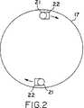
図2は,プレナムの閉じた遠方端部における入力ラインの実施例の断面図である。
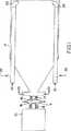
図3は,本発明の他の実施例の概略図である。
図1は,本発明に従って,有毒な廃棄物の無毒化システムの好適な形状を示す。このシステムは,搬送の可能性を維持するが,高効率で蒸気相において毒性物を処理するために設計される。電子線形加速器10が電子ビームを生成する。蒸気相の毒性物について,2MeVと3MeVとの間のエネルギーが,全体の処理システムの大きさの小型化と適切なビーム電力を与えることとの間で相互に良好に折り合う。蒸気相の毒性物を処理するために,約3kWのビーム電力を有する電子加速器が良好な処理のスループットを与える。低又は高電力システムも商業的に有用であり,1MeVから10MeVまでのエネルギーを生成する加速器が,例えば,使用され得る。
加速器からの電子ビームは,電子窓11を通じて移動し,それは典型的に,薄い金属の散乱体であり得る。典型的な電子窓の材料は,0.5ミルから数ミルの厚さで変化し,チタニウム,ステンレス鋼又はベリリウムを含むが,これらに限定されない。他の金属又はセラミックのような非金属でさえも使用され得る。
この加速器の電子窓は,加速器内の高真空を維持し,通常1〜3mmの直径で,加速器からの円筒状電子ビームを,方程式1で計算される角度の出力コーンへと散乱させる。電子窓の材料及び厚さの選択は,複号散乱角を決定するであろう。電子窓の材料及び厚さを選択することは,結局,所望の散乱角及び低いエネルギー損失を与えることであるが,良好な熱伝導を維持し,電子ビームにより窓で生成される熱応力を減少させる。この窓はまた,水で冷却され得る。
窓上の熱応力を減少させて,有効な電子ビームの直径を拡大するために,デフォーカシング・コイル(defocusing coil)14が使用され得る。散乱した電子ビームは,電子ビームによって形成されたオゾンを除去するために不活性ガスによってパージされるエンクロージャ(enclosure)15を通過する。散乱した電子ビームは,プレナムの窓16を通じてチェンバ15から出て,ここで,再度,方程式1に従って散乱する。プレナムで起きる化学プロセスが酸性蒸気の形成になることから,プレナムの窓は,シリコンカーバイドのような耐酸性材料から成る。プレナムの壁が,電子の衝突からのX線の形成を最小にするために,低原子番号のプラスチック又はその他の材料から成ってもよい。この材料は,鉛及びコンクリートのような遮蔽材料で被覆され,その領域で人間が操作できるようになっている。
電子ビームは,変換又は解毒のプレナム17内を通過する。プレナムの入力端部は,この実施例では,電子ビームよりも小さい直径の円筒状部分が続く円錐形である。プロセス効率に最適なプレナムの円錐角は,プレナムに入る電子ビームの散乱角がプレナムの円錐に近似的に整合するように設計され,電子ビームの殆どがプレナム内に向けられて,処理されるガスと相互作用する。
チェンバの設計が,加速器の窓及びプレナムの窓が,実施可能なかぎり接近させて配置されるべきである。これは,可能なかぎり狭い2個の窓からの複合電子ビーム散乱角になる。小さいプレナムの円錐角が,特に,搬送可能なシステムのための大きさ及び重さの実用的な制約に合致させるために要求され得る。また,プレナムの長さは,解毒されるガスの密度及びビームエネルギーのために最適化されるべきである。円錐角の制限についてもそうであるが,プレナム全長と,大きさ及び重さの実用的な考慮とで妥協することが必要であり得る。最大の効率と搬送性との間の妥協をとると,全長が約20フィートであることが適当となるようである。
電子ビームがプレナムに入射するとき,全ビーム電流の直接的な計測をするトロイド13を通過する。加速器のエネルギーが一定に維持されるので,ビーム電力が直接的に計測される。
有毒ガスが,2個のエントリー・パイプ21の手段によってプレナムに入射する。パイプは,プレナムの直径的に向かい合った側面に沿ってその遠方の端部へと内部に伸びている。各々の入力パイプの端部の肘部22(図2を参照)が,最初に,入ってくるガスをプレナムの遠方の端部の周囲の渦流れに向ける。しかし,入力パイプ21(及びもし必要ならば図示しない付加的な干渉手段)は,この流れのパターンを乱すために使用され,乱流を創り出す。当然に,入力は,エントリー・パイプ21に沿った穴から供給される。乱流が,プレナムを通じて流れるガスにわたって電子の一様なドーズを保証し,VOC分子が移動する経路の長さを増加させる。処理ガスが,プレナムの電子ビーム入力端部付近の一対のポート23を通じて出て行く。その端部は円錐状であり,電子ビームの入力点に向けて徐々に小さくなっているため,ガス分子は,逃げることなく,増加的に強くなる,入ってくる電子ビームに晒される。
円錐部分への電子ビームの入力点付近に位置したポート23が,処理ガスの出口となる。これらラインは,在来のガス洗浄装置(図示せず)に接続され,解毒プロセス中に形成されたいかなる酸をも処理する。洗浄されたガスは,次に,在来の吸収材料(例えば,チャコール)を通過する。吸収材料は,残留したいかなる有毒蒸気をも捕獲し,電子ビームが早期に非活性となった事態においてバックアップ・システムとして働く。しかし,これは,本発明のシステムにおいて必須の要素ではない。流入及び流出するガスが計器によってオン・ラインでモニターされ,入力及び出力ガスの毒性を決定する。ガスの入力及び出力温度及びガス流れの率もまたモニターされる。付加的なライン25は,プレナム内への様々な触媒作用の取入れを可能にするために付加され,反応プロセスを支援する。電子が,チェンバで,他のガス分子との衝突やチェンバの壁との衝突を含む多重の散乱プロセスを経る。VOCとの主な散乱電子の相互作用が,ガス流れでVOCを破壊する化学反応をもたらす。
在来の方法を通じてプレナムでのガスの温度及び圧力を変化させることもまた,ガスを解毒させる率に影響する。
プレナムの形状は,プレナムの上方又は入口部分が円錐状であるように設計される。プレナムの円錐角は,プレナムに入射する電子の複合散乱角に近似的に合致するように製作される。この角度は,加速器の窓及び/又はプレナムの窓のような窓によって創り出される散乱に従う。プレナムの長さが,処理されるガスの密度及び電子ビームのエネルギーに依存する。
例えば,電子が2.5MeVで注入されるとき,空気を通じて移動することができる飛程は,100%の吸収対して,約40フィートである。しかし,搬送可能なプレナムを対象とするならば,20フィートの長さのプレナムが一層有用であり重要であり,このようなプレナムが,適当な形状に造られるならば,32%の効率を達成できる。20フィート又は全吸収のための距離の約1/2で吸収される2.5MeVのビームの電子エネルギーは,全体の約2/3である。このような構造で,有毒分子を破壊するのに無効になる電子エネルギーの1/3をあきらめるか又は廃棄する。残り2/3のうちで,電子の約1/2が,チェンバの壁での散乱及び吸収を通じて廃棄又は失われ,32%の効率になる。
吸収効率が,散乱の窓の慎重な選択とチェンバの長さ及び形状に合致するようなエネルギーを最適化させることとによって変化される。
上記の例において,ビームのエネルギーは2.5MeVで注入され,よって,20フィートで通常,全部吸収され得た。もし,ビームが(例えば)1MeVで注入されたならば,全吸収のために期待される距離は約14フィート以内であったろう。異なるビームの全吸収の距離は,SP3012としてNASAにより発行され1964年に出版されたバーガー(Berger)及びセルツアー(Seltzer)による電子及び正電子のエネルギー損失及び範囲のテーブルにみられるような出版されたテーブルから決定され得る。
繰り返すが,1MeVのビームが使用されると,プレナムは約半分の全吸収距離又は約7フィートであるように設計されるであろう。このような場合,エネルギーが低いことから,方程式1のρβは一層小さく,角度Φoが増加されるという効果がある。これは,プレナムの円錐形状が維持されるならば一層の電子ビームがチェンバの壁に衝突しこの壁により失われ吸収され,このことから一層小さい効率のシステムを作り出すことを意味する。変形的に,プレナムの円錐部分の角度が,Φoの決定に合致しシステムの効率を向上させるために,増加され得る。一層大きい散乱角がプレナムの円錐部分によって合致される場合,プレナムは,一層大きい体積の処理されるガスを取り扱うことができ,及び/又は処理に対するガスのドエル(dwell)時間を増加させる機構を構成することができるであろう。
チェンバの角度もまた,システムを通じてガス流れの乱流を制御するために使用される。所望のドエル時間は,電子ビームフラックス,プレナム体積,蒸気がシステムを通じて移動する速度,ガス温度と同様に処理される蒸気の密度等のような因子に従うであろう。しかし,当業者は,相互に関係する要素を正確に画成し選択する適当なレベルで,動作可能なシステム及びこの開示の教示内で制御した効率の程度のシステムを創り出すことができるであろう。
磁気的な曲げ又は走査機構が加速器の端部に組み込まれ,プレナムの形状に合致するように造られるビーム分布を制御する。
プレナムは,プレナムを取り囲むアース(earth)がプレナムに関連して遮蔽要求を減少させる照射遮蔽として作用する土壌の穴(図3を参照)に垂直に挿入されるように設計される。変形的に,そして,図1に示すように,プレナムは,加速器モジュール,プレナム及び移動遮蔽が平台トラックに取り付けられるように,水平に方向付けられることができる。水平の方向付けが,用地から用地への搬送が簡単に達成されることから好適な構造であり,浄化用地でプレナムを保持し遮蔽する深い穴が不要となる。
解毒チェンバが一般に,石炭及び石油の火力発電プラントの使用のために設計された大きなシステムであった。これらチェンバの設計が,硫黄及び窒素の酸化物の減少のための自己遮蔽封じ込めシステムを与えることにしぼられた。チェンバの設計の効率を増加し又はガス蒸気のドエル時間を制御し又はシステムを効率的にし又は搬送可能にすることを全く試みなかった。その結果,これらシステムは,非効率的になり,本高効率システムで達成されるときの化学的結合を破壊しなかった。
図3を参照すると,大気圧での蒸気照射システムの他の実施例が示されている。プレナム31がその全長にわたって円錐状であり,その垂直に方向付けられた軸線で土壌に埋められ動作され得る。遮蔽が,このような場合,取り囲んでいるアース(earth)によって達成される。プレナムに接続された加速器32は,400Wの平均ビームを生成した2.5MeVの電子加速器であった。図1に示されるようなプレナムの設計を使用するこのシステムは,実際の野外試験で首尾良く利用され,湿気のある空気流にあるトリクロロエチレン(TCE)蒸気を500kRまでの電子ドーズに晒した。毒性を破壊することについて非常に良好な効率が信頼性をもって示された。しかし,良好な結果はまた,90kRと同様に低い電子ドーズで得られた。
プレナムの設計は,プレナムの上部の組み合わせカラー33で加速器に接続するガス漏れのない,プレナムの軸線に整列する円錐状強化構造をもつものである。電子が,ビームも拡散しプレナムの狭い端部を密閉する窓35を通じてプレナムに入射する。窓35が電子ビームを連続した実円錐角に散乱させ,プレナムの全体の体積が照射される。この実施例においては,窓35は,数ミルの厚さのプラスチック層の散乱体によって裏張りされてた数ミルの厚さのステンレス鋼フォイルである。加速器出力窓36及びプレナムの窓35の両方は,窒素入口37及び窒素出口38を通じる窒素ガス流れによって冷却される。ここで,プレナムは,20フィートの高さであった。
VOCが,ベースにある蒸気入力040及び41を通じてプレナムに入力する。蒸気は,次に,それがプレナム31の上部の蒸気出口42及び43に向かって移動するとき,プレナムを通過する電子ビームに晒される。この場合,ベースにあるサンプ(sump)45が蒸気の湿気から生じる液体凝縮物を収集する。サンプによって収集された液体が,その後,抽出管46を通じて抽出され得る。
実際の動作において,このシステムは,270CFMの率で土壌から吸引されたTCE蒸気を首尾良く処理することができた。入力ガスが,60ppmで計測された不純物を含んでいた。プロセスを続けると,存在するガスは再び計測され,不純物が,入手可能な計器の検出性の限界である0.1ppmとなったことがわかった。
本発明が特定的な実施例及び動作で説明されてきたが,この説明が図説の目的のためのみであり,本発明が上述の開示及び教示の変更物及び変形物を可能にすることが理解されるべきである。したがって,本発明がここに示した特定的な説明及び実施例以外で実施でき,添付の請求の範囲に示されるように本発明は広範囲に保護されるべきことを意図としていることが理解される。BACKGROUND ART Hazardous volatile organic compounds (VOCs) in soil and groundwater pose a significant health hazard if the aquifers supplying water to population centers are contaminated. Current detoxification methods for soil and groundwater treatment include air stripping, vacuum extraction, carbon entrapment, ashing / oxidation and biodetoxification.
Air stripping and vacuum extraction is a divergence technique that extracts steam (the terms vapor, VOC and gas are used interchangeably) from the soil and releases pollutants into the steam. is there. Although these techniques can remove or reduce the threat of groundwater pollution at a relatively low cost, they only change the medium of pollution from soil to air and are not environmentally desirable. The release of pollutants is controversial and its use in the future is severely limited by air quality standards.
Carbon confinement is a collective technique for vapor from a steam extraction well or other VOC source passing through a carbon (or other absorbent) -filled canister to absorb VOCs. Collective technology prevents or limits groundwater pollution by reducing pollution levels and is cost effective for flow rates and pollution levels. However, confinement technology is not a destructive technology, so it is necessary to remove and process the collected VOCs. Also, the confinement technology is not effective for some low absorption VOCs and is not generally effective.
Ashing relates to burning waste from air stripped groundwater or soil for the destruction of VOCs at high temperatures. Ashing is very problematic, often incomplete and costly. Incomplete destruction can produce a more dangerous substance than the original pollutant and release it into the air.
An object of the present invention is to achieve safe and effective destruction of various VOCs based on the prior art.
DISCLOSURE OF THE INVENTION The present invention includes an apparatus for a steam extraction device. Toxic vapors from soil or groundwater or other sources are incident on a detoxification plenum where a strong electron beam is emitted. The electrons interact with toxic vapors, causing chemical conversion within the reaction plenum.
Chemical conversion of volatile organic chemicals and chemicals through electron beam processing
1. Direct dechlorination to produce reactive organic intermediates that are decomposed into inorganic chloride ions and unreacted compounds;
2. the production of organic and inorganic free radicals and reactive ions which, as a result of the reaction, destroy the hazardous material of the target;
3. Formation of hydrophilic electrons (in water vapor) that can weaken chemical bonds,
including.
Free radical catalysts or scavengers are added to change the composition or composition of the environmentally complete reaction product.
Online monitors (gas chromatographs, volume flow meters, pressure gauges) are used to measure the extent or breakdown of chemical transformations, and electrical circuits (dosimeters, current and voltage monitors) measure the operating power level of the electron beam Used for As a backup, the carbon aggregate canister is used as a trap to absorb dangerous volatiles that have not been completely converted or destroyed during processing.
The use of the electron beam for reducing the emission ofthe prior art <br/> sulfur oxides from power plant facility in the prior art (SOx) and / or nitrogen oxides (NOx) have been disclosed, the VOC destruction The movable and effective devices are not described. This prior art describes how exhaust gas from a power plant is directed to a reaction chamber that is irradiated by an electron beam before the power plant is exhausted as flue gas. If the beam power is high enough, irradiation from the electron beam will substantially (but not completely eliminate) SOx and NOx emissions from the flue gas. Various methods for removing 90% of SOx and NOx emissions are claimed.
In one approach, electron beam irradiation is used to convert SOx and NOx to fog and solid particles passing through a dust collector to reduce emissions. In another approach, air is introduced into a reaction chamber where irradiation with an electron beam forms ozone and oxygen atoms. Thereafter, irradiated air is mixed with the waste gas for the oxidation of NO in the gas to form a NO2. The treated gas is introduced into a moisture absorption tower for desulfurization and denitration effects. Another approach is to use an electron beam to form reactive atoms such as O and OH groups in the irradiated waste gas, after which the O and OH groups are removed where the SOx and NOx components are removed. Released into main waste gas. These are disclosed in, for example, U.S. Patent Nos. 4,507,265, 5,015,443, 4,596,642 and 4,915,916. In U.S. Pat. No. 4,969,984, ammonia is added as a means to reduce SOx and NOx emitted from flue gas.
These prior art approaches were in treating large volumes of effluent from power plants (typically 10,000 cubic feet per minute). These large volume flows adopt some stationary electron beam accelerators with a beam power of 100 kW. The electron generators described in these patents are of the DC type and have low energy beams, typically in the range of 100-500 keV.
These prior art reaction chambers were designed as storage vessels for effluent smoke and as shielding for radiation. The reaction chambers and electron sources in these references are large and heavy. Furthermore, since the aim was to reduce the emission of unpleasant substances, the interest was only in the inefficiency of the radiation treatment process in the reaction chamber. The effluent itself is very high in these devices and not all is treated.
SUMMARY OF THE INVENTION The objects of the invention are achieved by the use of a newly designed reaction or conversion plenum or chamber, and by the use of a powerful electron source and a device that allows for more effective emission of the vapor to be treated. The plenum design includes special features that optimize the conversion process to increase efficiency by at least 20% to preferably 32%. These efficiencies (percentage of electrons in the beam that strike the toxic molecule and cause a chemical transformation) were calculated by Monte Carlo and confirmed by measurements of the treated gas.
In the present invention, the plenum is located close to the electron accelerator. The toxic gases enter the plenum and are chemically converted into environmentally safe by-products by the electron beam generated by the electron linac.
The plenum shape is designed to optimize the effect of the electron beam interaction with the process gas. When the electron beam is incident on the reaction plenum or chamber, it is conically scattered from the exit window of the electron accelerator where the electron beam is generated, and secondly from other windows separating the accelerator from the plenum. . The scattering angle depends on the energy of the electron beam and the thickness and material of the window. Electron beam scattering follows the following equation:
Other objects and advantages of the present invention will become more apparent to those skilled in the art from the following drawings and detailed description.
Drawings and brief description FIG. 1 is a schematic diagram of the system of the present invention.
FIG. 2 is a cross-sectional view of an embodiment of the input line at the closed distal end of the plenum.
FIG. 3 is a schematic diagram of another embodiment of the present invention.
FIG. 1 shows a preferred form of a toxic waste detoxification system according to the present invention. The system is designed to maintain toxic properties in the vapor phase with high efficiency while maintaining transportability. An electron
The electron beam from the accelerator travels through the electron window 11, which can typically be a thin metal scatterer. Typical electronic window materials vary in thickness from 0.5 mils to several mils and include, but are not limited to, titanium, stainless steel or beryllium. Other metals or even non-metals such as ceramics can be used.
The electron window of the accelerator maintains a high vacuum in the accelerator and scatters a cylindrical electron beam from the accelerator, typically 1 to 3 mm in diameter, into the output cone at an angle calculated by equation 1. The choice of material and thickness of the electronic window will determine the compound scattering angle. Choosing the material and thickness of the electron window, while ultimately giving the desired scattering angle and low energy loss, will maintain good heat conduction and reduce the thermal stress generated in the window by the electron beam. Let it. This window can also be cooled with water.
A defocusing
The electron beam passes through a
The design of the chamber should be such that the windows of the accelerator and the windows of the plenum are as close as practicable. This results in a composite electron beam scattering angle from two windows as narrow as possible. A small plenum cone angle may be required to meet practical size and weight constraints, especially for transportable systems. Also, the length of the plenum should be optimized for the density and beam energy of the gas being detoxified. As with the cone angle limitation, a compromise may need to be made between the overall plenum length and practical considerations of size and weight. A compromise between maximum efficiency and transportability seems to be appropriate for a total length of about 20 feet.
As the electron beam enters the plenum, it passes through a
Toxic gas enters the plenum by means of two
The
Varying the temperature and pressure of the gas in the plenum through conventional methods also affects the rate at which the gas is detoxified.
The plenum shape is designed such that the upper or inlet portion of the plenum is conical. The cone angle of the plenum is fabricated to approximately match the compound scattering angle of the electrons incident on the plenum. This angle is in accordance with the scatter created by windows such as accelerator windows and / or plenum windows. The length of the plenum depends on the density of the gas being processed and the energy of the electron beam.
For example, when electrons are injected at 2.5 MeV, the range that can travel through air is about 40 feet for 100% absorption. However, if the target is a transportable plenum, a 20-foot-long plenum is more useful and important, and if such a plenum is properly shaped, 32% efficiency can be achieved. it can. The electron energy of a 2.5 MeV beam absorbed at 20 feet or about half the distance for total absorption is about 2/3 of the total. Such a structure gives up or discards one-third of the electron energy that is ineffective at destroying toxic molecules. Of the remaining two-thirds, about one-half of the electrons are discarded or lost through scattering and absorption at the chamber wall, resulting in a 32% efficiency.
The absorption efficiency is varied by careful selection of the scattering window and optimizing the energy to match the length and shape of the chamber.
In the above example, the energy of the beam was injected at 2.5 MeV, and thus could normally be totally absorbed at 20 feet. If the beam was injected at (for example) 1 MeV, the expected distance for total absorption would be within about 14 feet. The total absorption distances of the different beams are published as shown in the table of electron and positive electron energy losses and ranges by Berger and Seltzer published by NASA as SP3012 and published in 1964. Can be determined from the table.
Again, if a 1 MeV beam is used, the plenum would be designed to be about half the total absorption distance or about 7 feet. In this case, since the energy is low, Robeta equation 1 even smaller, there is an effect that the angle [Phio is increased. This means that if the conical shape of the plenum is maintained, more electron beams will impinge upon and be lost and absorbed by the walls of the chamber, thus creating a less efficient system. Alternatively, the angle of the conical portion of the plenum may be increased to meet the determination of Φo and improve the efficiency of the system. If a larger scattering angle is matched by the conical portion of the plenum, the plenum can handle a larger volume of gas to be treated and / or provide a mechanism to increase gas dwell time for treatment. Could be done.
The angle of the chamber is also used to control the turbulence of the gas flow through the system. The desired dwell time will depend on factors such as electron beam flux, plenum volume, the rate at which the steam travels through the system, the density of the steam being processed as well as the gas temperature. However, those skilled in the art will be able to create systems that are operable and of a controlled degree of efficiency within the teachings of this disclosure at the appropriate level to accurately define and select the interrelated elements. .
A magnetic bending or scanning mechanism is incorporated at the end of the accelerator to control the beam distribution created to conform to the plenum shape.
The plenum is designed such that the earth surrounding the plenum is inserted vertically into a hole in the soil (see FIG. 3) that acts as an radiation shield that reduces shielding requirements in relation to the plenum. Alternatively, and as shown in FIG. 1, the plenum can be oriented horizontally such that the accelerator module, plenum and moving shield are mounted on a flatbed truck. A horizontal orientation is a preferred structure because the transfer from site to site is easily achieved, and eliminates the need for deep holes to hold and shield the plenum at the purification site.
Detoxification chambers have generally been large systems designed for use in coal and oil fired power plants. The design of these chambers was determined to provide a self-shielding containment system for sulfur and nitrogen oxide reduction. No attempt was made to increase the efficiency of the chamber design or to control the dwell time of the gas vapor or to make the system efficient or transportable. As a result, these systems became inefficient and did not destroy the chemical bonds that were achieved with this high efficiency system.
Referring to FIG. 3, another embodiment of the steam irradiation system at atmospheric pressure is shown. The
The plenum design has a gas-tight, conical reinforcement structure aligned with the plenum axis that connects to the accelerator with a
VOCs enter the plenum through
In practical operation, this system was able to successfully treat TCE vapor sucked from soil at a rate of 270 CFM. The input gas contained impurities measured at 60 ppm. As the process continued, the gases present were re-measured, indicating that the impurities had reached the limit of 0.1 ppm, the detectable limit of available instruments.
Although the present invention has been described in particular embodiments and operations, it is understood that this description is for illustrative purposes only and that the invention allows for variations and modifications of the above disclosure and teachings. It should be. It is, therefore, to be understood that the invention may be practiced other than as specifically described and practiced, and that the invention is intended to be broadly protected as set forth in the appended claims. .
Claims (31)
Translated fromJapanese揮発性有機化合物を処理するための反応プレナム(17、31)、
該反応プレナムに揮発性有機化合物を流入させる手段(40、41)、
前記反応プレナムの近傍に配置される高エネルギーの電子ビーム発生器(10、32)、
該電子ビーム発生器において、高真空中で形成され、加速された高エネルギーの電子ビームを、前記反応プレナムと前記電子ビーム発生器との間にある薄い散乱窓を通して、前記反応プレナム中で、電子と前記反応プレナムの中を流れる揮発性有機化合物とが相互作用するように向ける手段、および
前記相互作用の後、前記プレナムから外に流出物を流す手段(42および43)、
を含み、
前記反応プレナムは散乱して広がったエネルギーをもった電子ビームで満たされ、前記反応プレナム中での電子と揮発性有機化合物との間の相互作用が化学的な中間生成物を生成し、その化学的な中間生成物と電子と間の相互作用が連続して、該中間生成物をより環境的に受け入れ可能な化学物質に変換し、前記反応プレナムの長さおよび容積は電子ビームのエネルギーに依存する、
ことを特徴とする処理システム。Volatile organic compounds tobe treated flow into the reaction plenum (40 and 41), where they are treatedand exit therefrom asenvironmentallyacceptable effluents (42 and 43), and thevolatilization of thegaseous statesex organic compound is converted into chemicalscan accept environmentally, a volatile organic compound processing system,
A reaction plenum (17, 31) for treating volatile organic compounds,
Means(40, 41)for flowing a volatile organic compound into the reaction plenum;
Ahigh-energy electron beam generator (10, 32) located near saidreaction plenum;
In electron beam generator is formed in a high vacuum,an electron beam of high energy isaccelerated,andthrough the thin scattering window located between the electron beam generator andthe reaction plenarybeam, said reactionMeans in the plenumfordirectingelectrons tointeract with volatile organic compounds flowing in thereaction plenum; and means for flowing effluent out of the plenum after the interaction. And 43),
Only including,
The reaction plenumfilled with an electron beamhavingan energy spreadscattered,the interaction between theelectronand the volatile organic compoundsin the reactionplenumto produce achemical intermediate rawNarubutsu, its chemical intermediate products andare contiguousthe interactionbetween electrons andconverts the intermediate product more environmentally receivedininputis available chemicals, contact lengthand volumeof said reactionplenumelectronic Depends on the energy of the beam,
A processing system, characterized in that:
Applications Claiming Priority (3)
| Application Number | Priority Date | Filing Date | Title |
|---|---|---|---|
| US07/941,788US5319211A (en) | 1992-09-08 | 1992-09-08 | Toxic remediation |
| US07/941,788 | 1992-09-08 | ||
| PCT/US1993/007518WO1994006149A1 (en) | 1992-09-08 | 1993-08-11 | Toxic remediation system and method |
Publications (2)
| Publication Number | Publication Date |
|---|---|
| JPH08504123A JPH08504123A (en) | 1996-05-07 |
| JP3578215B2true JP3578215B2 (en) | 2004-10-20 |
Family
ID=25477064
Family Applications (1)
| Application Number | Title | Priority Date | Filing Date |
|---|---|---|---|
| JP50719294AExpired - Fee RelatedJP3578215B2 (en) | 1992-09-08 | 1993-08-11 | Apparatus and method for detoxifying toxic substances |
Country Status (7)
| Country | Link |
|---|---|
| US (2) | US5319211A (en) |
| EP (1) | EP0659297B1 (en) |
| JP (1) | JP3578215B2 (en) |
| AU (1) | AU5004293A (en) |
| CA (1) | CA2144082C (en) |
| DE (1) | DE69332409T2 (en) |
| WO (1) | WO1994006149A1 (en) |
Families Citing this family (31)
| Publication number | Priority date | Publication date | Assignee | Title |
|---|---|---|---|---|
| US5530255A (en)* | 1990-08-17 | 1996-06-25 | Raychem Corporation | Apparatus and methods for electron beam irradiation |
| JPH0671134A (en)* | 1992-07-09 | 1994-03-15 | Toshiba Corp | Apparatus and method for removing carbon dioxide in exhaust gas |
| US5357291A (en)* | 1992-09-08 | 1994-10-18 | Zapit Technology, Inc. | Transportable electron beam system and method |
| US5483074A (en)* | 1995-01-11 | 1996-01-09 | Litton Systems, Inc. | Flood beam electron gun |
| WO1996024805A1 (en)* | 1995-02-08 | 1996-08-15 | James Winchester | Process and device for destroying hazardous compounds in incinerator flue gas |
| US5623183A (en)* | 1995-03-22 | 1997-04-22 | Litton Systems, Inc. | Diverging beam electron gun for a toxic remediation device with a dome-shaped focusing electrode |
| US5621270A (en)* | 1995-03-22 | 1997-04-15 | Litton Systems, Inc. | Electron window for toxic remediation device with a support grid having diverging angle holes |
| JP2000516382A (en)* | 1996-08-13 | 2000-12-05 | 株式会社荏原製作所 | Electron beam irradiation device |
| JPH10216460A (en)* | 1997-01-31 | 1998-08-18 | Hitachi Ltd | Electron beam gas processing equipment |
| WO2000042620A1 (en)* | 1999-01-11 | 2000-07-20 | Ebara Corporation | Electron beam projection reaction device |
| RU2221636C2 (en)* | 1999-07-02 | 2004-01-20 | Ибара Корпорейшн | Method and device for irradiation with electron beam |
| US7424764B2 (en)* | 1999-09-01 | 2008-09-16 | Hagleitner Hygiene International Gmbh | Brush with locking and detaching structure for disposable head |
| US6623706B2 (en) | 2000-06-20 | 2003-09-23 | Advanced Electron Beams, Inc. | Air sterilizing system |
| US7189978B2 (en)* | 2000-06-20 | 2007-03-13 | Advanced Electron Beams, Inc. | Air sterilizing system |
| US6623705B2 (en)* | 2000-06-20 | 2003-09-23 | Advanced Electron Beams, Inc. | Gas conversion system |
| WO2002058742A1 (en) | 2000-12-13 | 2002-08-01 | Advanced Electron Beams, Inc. | Decontamination apparatus |
| US7183563B2 (en)* | 2000-12-13 | 2007-02-27 | Advanced Electron Beams, Inc. | Irradiation apparatus |
| JP2002336836A (en)* | 2001-05-14 | 2002-11-26 | Japan Atom Energy Res Inst | Device for purifying solids contaminated with dioxins and / or polychlorinated biphenyls |
| KR20030086907A (en)* | 2002-05-03 | 2003-11-12 | 김조천 | Hybrid apparatus and method for removing volatile organic compounds and odorous substances by electron beam and catalyst |
| KR100375833B1 (en)* | 2002-05-16 | 2003-03-12 | Boram E & T Co Ltd | Apparatus for eliminating volatile organic compounds using electronic beam and catalyst |
| JP2004098035A (en)* | 2002-09-13 | 2004-04-02 | Japan Atom Energy Res Inst | Decomposition method of dioxins in smoke and exhaust gas by electron beam irradiation |
| US7148613B2 (en) | 2004-04-13 | 2006-12-12 | Valence Corporation | Source for energetic electrons |
| US20060113486A1 (en)* | 2004-11-26 | 2006-06-01 | Valence Corporation | Reaction chamber |
| WO2006086645A1 (en)* | 2005-02-10 | 2006-08-17 | Northampton Community College | Method for the reduction of malodorous compounds |
| US7656236B2 (en) | 2007-05-15 | 2010-02-02 | Teledyne Wireless, Llc | Noise canceling technique for frequency synthesizer |
| US8179045B2 (en) | 2008-04-22 | 2012-05-15 | Teledyne Wireless, Llc | Slow wave structure having offset projections comprised of a metal-dielectric composite stack |
| DE102011080262A1 (en)* | 2011-08-02 | 2013-02-07 | Krones Aktiengesellschaft | Warm sterilization of water |
| US9202660B2 (en) | 2013-03-13 | 2015-12-01 | Teledyne Wireless, Llc | Asymmetrical slow wave structures to eliminate backward wave oscillations in wideband traveling wave tubes |
| FR3006602B1 (en)* | 2013-06-10 | 2016-01-29 | Vivirad | DEVICE FOR TREATING AT LEAST ONE FLOW OF GASEOUS EFFLUENTS |
| US11465920B2 (en)* | 2019-07-09 | 2022-10-11 | Fermi Research Alliance, Llc | Water purification system |
| FR3157220A1 (en)* | 2023-12-20 | 2025-06-27 | Commissariat A L'energie Atomique Et Aux Energies Alternatives | Process for purifying a gas |
Family Cites Families (20)
| Publication number | Priority date | Publication date | Assignee | Title |
|---|---|---|---|---|
| US2583899A (en)* | 1950-11-29 | 1952-01-29 | Lester H Smith | Electrochemical process |
| US2892946A (en)* | 1955-11-25 | 1959-06-30 | High Voltage Engineering Corp | Method of and apparatus for the more efficient use of high-energy charged particles in the treatment of gasphase systems |
| US4702808A (en)* | 1957-06-27 | 1987-10-27 | Lemelson Jerome H | Chemical reaction apparatus and method |
| US2958638A (en)* | 1958-04-24 | 1960-11-01 | Exxon Research Engineering Co | Reaction container for carrying out radiation induced chemical reactions |
| JPS58884B2 (en)* | 1978-12-29 | 1983-01-08 | 株式会社荏原製作所 | Exhaust gas treatment method using radiation irradiation |
| JPS5844009B2 (en)* | 1978-12-29 | 1983-09-30 | 株式会社荏原製作所 | Electron beam irradiation treatment method for exhaust gas and its equipment |
| JPS5940051B2 (en)* | 1979-07-11 | 1984-09-27 | 株式会社荏原製作所 | Electron beam irradiation exhaust gas treatment equipment |
| US4372832A (en)* | 1981-01-21 | 1983-02-08 | Research-Cottrell, Incorporated | Pollution control by spray dryer and electron beam treatment |
| SU1134548A2 (en)* | 1983-08-23 | 1985-01-15 | Предприятие П/Я Р-6601 | Apparatus for neutralizing waste liquors |
| DE3403726A1 (en)* | 1984-02-03 | 1985-08-08 | Polymer-Physik GmbH & Co KG, 2844 Lemförde | METHOD AND DEVICE FOR DESULFURING AND DENITRATING SMOKE GASES BY ELECTRON RADIATION |
| DE3513633C2 (en)* | 1985-04-16 | 1994-06-16 | Polymer Physik Gmbh | Device for the desulphurization and denitrification of flue gases by electron radiation |
| DE3524729A1 (en)* | 1985-07-11 | 1987-01-15 | Leybold Heraeus Gmbh & Co Kg | DEVICE FOR CLEANING SMOKE GASES SULFUR AND NITROGEN |
| DE3620673A1 (en)* | 1985-10-23 | 1987-12-23 | Licentia Gmbh | METHOD FOR IRRADIATING GAS-SHAPED MEDIA, PREFERABLY SMOKE GASES, WITH ELECTRON BEAMS |
| JPS62250933A (en)* | 1986-04-24 | 1987-10-31 | Ebara Corp | Exhaust gas treatment method and device using electron beam irradiation |
| DE3761531D1 (en)* | 1986-05-30 | 1990-03-08 | Noell Gmbh | METHOD AND DEVICE FOR SIMULTANEOUS SEPARATION OF SULFUR DIOXIDE AND NITROGEN. |
| DE3877834T2 (en)* | 1987-05-30 | 1993-05-19 | Ebara Corp | METHOD FOR TREATING EXHAUST GAS. |
| US4969984A (en)* | 1987-06-01 | 1990-11-13 | Ebara Corporation | Exhaust gas treatment process using irradiation |
| US5219534A (en)* | 1991-04-26 | 1993-06-15 | Reynolds Warren D | Process and apparatus for decontaminating air |
| EP0540756B1 (en)* | 1991-05-21 | 1997-01-02 | Institute Of Nuclear Chemistry And Technology | A PROCESS FOR REMOVAL OF SO 2? AND NO x? FROM COMBUSTION FLUE GASES AND AN APPARATUS USED THEREFOR |
| US5357291A (en)* | 1992-09-08 | 1994-10-18 | Zapit Technology, Inc. | Transportable electron beam system and method |
- 1992
- 1992-09-08USUS07/941,788patent/US5319211A/ennot_activeExpired - Lifetime
- 1993
- 1993-08-11DEDE69332409Tpatent/DE69332409T2/ennot_activeExpired - Fee Related
- 1993-08-11EPEP93919953Apatent/EP0659297B1/ennot_activeExpired - Lifetime
- 1993-08-11CACA002144082Apatent/CA2144082C/ennot_activeExpired - Fee Related
- 1993-08-11JPJP50719294Apatent/JP3578215B2/ennot_activeExpired - Fee Related
- 1993-08-11WOPCT/US1993/007518patent/WO1994006149A1/enactiveIP Right Grant
- 1993-08-11AUAU50042/93Apatent/AU5004293A/ennot_activeAbandoned
- 1994
- 1994-06-03USUS08/253,967patent/US5539212A/ennot_activeExpired - Lifetime
Also Published As
| Publication number | Publication date |
|---|---|
| US5319211A (en) | 1994-06-07 |
| JPH08504123A (en) | 1996-05-07 |
| EP0659297A4 (en) | 1998-12-09 |
| US5539212A (en) | 1996-07-23 |
| EP0659297B1 (en) | 2002-10-16 |
| AU5004293A (en) | 1994-03-29 |
| WO1994006149A1 (en) | 1994-03-17 |
| EP0659297A1 (en) | 1995-06-28 |
| CA2144082A1 (en) | 1994-03-17 |
| DE69332409D1 (en) | 2002-11-21 |
| CA2144082C (en) | 1999-10-12 |
| DE69332409T2 (en) | 2003-06-18 |
Similar Documents
| Publication | Publication Date | Title |
|---|---|---|
| JP3578215B2 (en) | Apparatus and method for detoxifying toxic substances | |
| US5357291A (en) | Transportable electron beam system and method | |
| JP3519408B2 (en) | Processing unit, processing system, and electron beam source used for converting and processing volatile organic compounds using electrons | |
| US5750823A (en) | Process and device for destruction of halohydrocarbons | |
| Lee et al. | Abatement of gas-phase p-xylene via dielectric barrier discharges | |
| RU2113889C1 (en) | METHOD OF REMOVAL OF SO2 AND NOx FROM COMBUSTION PRODUCTS OF FUEL GASES AND DEVICE FOR REALIZATION OF THIS METHOD | |
| Calinescu et al. | E-Beam SO2 and NOx removal from flue gases in the presence of fine water droplets | |
| Zheng et al. | Destruction of PCDD/Fs by gliding arc discharges | |
| RU2077936C1 (en) | Method of detoxification of exhaust gas from polycyclic aromatic hydrocarbons | |
| CA2903174C (en) | Waste disposal | |
| US5807491A (en) | Electron beam process and apparatus for the treatment of an organically contaminated inorganic liquid or gas | |
| US5886316A (en) | Method and apparatus for treating waste and for obtaining usable by-product | |
| US5648592A (en) | Method and apparatus for treating waste and for obtaining usable by-product | |
| KR102214295B1 (en) | Device for treating at least one gaseous effluent stream and corresponding treatment method | |
| Kholodnaya et al. | Plasma chemical purification of flue gases using pulsed electron beams | |
| Chmielewski et al. | „Nuclear Technology for Cleaning Coal Emissions” | |
| Han et al. | Applications of industrial electron accelerators at Samsung Heavy Industries | |
| Ighigeanu et al. | High-Energy Electron Beam Application to Air Pollutants Removal | |
| Gorshkov et al. | Application of concentrated electron beams in extra vacuum technologies | |
| Lovtsov et al. | Electron-Beam Systems For Realization of Plasma Technologies | |
| DANIEL | Processing of Waste | |
| Hashim | Removal of nitric oxide (no) using high energy electron beam and dielectric barrier discharge/Siti A'iasah Binti Hashim | |
| Hashim | Removal of Nitric Oxide (NO) Using High Energy Electron Beam and Dielectric Barrier Discharge | |
| Rosocha et al. | Short-pulsed, electric-discharge degradation of toxic and sludge wastes | |
| KR20140058766A (en) | Apparatus and method for removing mercury from gases utilizing electron-beam irradiation |
Legal Events
| Date | Code | Title | Description |
|---|---|---|---|
| A02 | Decision of refusal | Free format text:JAPANESE INTERMEDIATE CODE: A02 Effective date:20031202 | |
| A521 | Request for written amendment filed | Free format text:JAPANESE INTERMEDIATE CODE: A821 Effective date:20040301 | |
| A521 | Request for written amendment filed | Free format text:JAPANESE INTERMEDIATE CODE: A523 Effective date:20040330 | |
| A521 | Request for written amendment filed | Free format text:JAPANESE INTERMEDIATE CODE: A821 Effective date:20040514 | |
| A521 | Request for written amendment filed | Free format text:JAPANESE INTERMEDIATE CODE: A821 Effective date:20040514 | |
| A911 | Transfer to examiner for re-examination before appeal (zenchi) | Free format text:JAPANESE INTERMEDIATE CODE: A911 Effective date:20040603 | |
| A131 | Notification of reasons for refusal | Free format text:JAPANESE INTERMEDIATE CODE: A131 Effective date:20040608 | |
| A521 | Request for written amendment filed | Free format text:JAPANESE INTERMEDIATE CODE: A523 Effective date:20040615 | |
| TRDD | Decision of grant or rejection written | ||
| A01 | Written decision to grant a patent or to grant a registration (utility model) | Free format text:JAPANESE INTERMEDIATE CODE: A01 Effective date:20040707 | |
| A61 | First payment of annual fees (during grant procedure) | Free format text:JAPANESE INTERMEDIATE CODE: A61 Effective date:20040707 | |
| R150 | Certificate of patent or registration of utility model | Free format text:JAPANESE INTERMEDIATE CODE: R150 | |
| FPAY | Renewal fee payment (event date is renewal date of database) | Free format text:PAYMENT UNTIL: 20070723 Year of fee payment:3 | |
| FPAY | Renewal fee payment (event date is renewal date of database) | Free format text:PAYMENT UNTIL: 20080723 Year of fee payment:4 | |
| LAPS | Cancellation because of no payment of annual fees |