JP3577653B2 - Dental gas laser device - Google Patents
Dental gas laser deviceDownload PDFInfo
- Publication number
- JP3577653B2 JP3577653B2JP19052196AJP19052196AJP3577653B2JP 3577653 B2JP3577653 B2JP 3577653B2JP 19052196 AJP19052196 AJP 19052196AJP 19052196 AJP19052196 AJP 19052196AJP 3577653 B2JP3577653 B2JP 3577653B2
- Authority
- JP
- Japan
- Prior art keywords
- laser
- laser resonator
- optical waveguide
- resonator
- dental
- Prior art date
- Legal status (The legal status is an assumption and is not a legal conclusion. Google has not performed a legal analysis and makes no representation as to the accuracy of the status listed.)
- Expired - Fee Related
Links
Images


Classifications
- A—HUMAN NECESSITIES
- A61—MEDICAL OR VETERINARY SCIENCE; HYGIENE
- A61C—DENTISTRY; APPARATUS OR METHODS FOR ORAL OR DENTAL HYGIENE
- A61C1/00—Dental machines for boring or cutting ; General features of dental machines or apparatus, e.g. hand-piece design
- A61C1/0046—Dental lasers
Landscapes
- Health & Medical Sciences (AREA)
- Life Sciences & Earth Sciences (AREA)
- Optics & Photonics (AREA)
- Oral & Maxillofacial Surgery (AREA)
- Dentistry (AREA)
- Epidemiology (AREA)
- Physics & Mathematics (AREA)
- Animal Behavior & Ethology (AREA)
- General Health & Medical Sciences (AREA)
- Public Health (AREA)
- Veterinary Medicine (AREA)
- Laser Surgery Devices (AREA)
- Dental Tools And Instruments Or Auxiliary Dental Instruments (AREA)
Description
Translated fromJapanese【0001】
【発明の属する技術分野】
本発明は、レーザ光を口腔内の硬組織に作用させて蒸発,凝固,止血,殺菌等の効果をもたらす歯科用気体レーザ装置に関する。
【0002】
【従来の技術】
近年、レーザ手術装置は、光導波路の改良(多関節ミラー型から柔軟性のある光ファイバへの改良)により、外科的ばかりでなく内視鏡手術にも幅広く適用されつつある。また、最近では口腔外科での好成果により、従来では未認可であった歯科硬組織領域への適用も盛んに研究され始めてきている。
【0003】
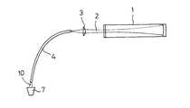
この種のレーザ手術装置は、一般的には図2に示すように構成され、レーザ共振器1から出射されたレーザ光2は、集光レンズ3で小さな点に絞られ、光導波路4により目的の場所へ伝送される。なお、図中の7は被照射体、10は光導波路4の先端から出射される照射レーザ光である。
【0004】
ところで、レーザ光2を発生するレーザ共振器1は、発生させるレーザの波長によって、その構成が多少異なる。現在、ファイバ導光式レーザとして最も普及しているのは、固体レーザの一種であるNd(ネオジウム)−YAG(イットリウム・アルミニウム・ガーネット)レーザ(波長1.06μm)と石英製光ファイバとの組み合わせであり、数百W級の大出力までの伝送が可能になっている。
【0005】
しかし、図3に示すように、前記波長のレーザ光は、生体の主成分である水や骨組織への吸収が少ないため深達距離が長く、目に見えない深部組織までレーザ光の影響を受けやすい。
【0006】
このため、医療用レーザとして実用面から最も期待されているのは、水や骨に効率よく吸収する中遠赤外波長のレーザであり、実用化の最も進んでいる波長
10.6μmの炭酸ガスレーザ、および波長5.6μmの一酸化炭素ガスが重要視されている。一般に、気体レーザの励起方法は放電励起であり、フラッシュランプで励起する固体レーザのような短パルスは原理的に得にくい。
【0007】
放電励起型気体レーザ装置は、もともと連続発振を高出力・高効率にて取り出せるレーザとして開発されてきたものであり、また、従来のレーザ手術装置の主目的が生体軟組織を能率良く切開,蒸発させることにあったため、連続出力もしくはパルス幅の比較的長い(0.1秒以上)パルス出力のものが多い。
【0008】
これらの波長に対しては、前記石英ファイバでは光を吸収してしまい、透過させることが不可能であり、高出力レーザを導光できる高性能光ファイバの開発は遅れており、現在、最も研究されているものである。
【0009】
図4に示すように、例えば、波長5〜15μmのレーザ光に対しては銀ハライド系結晶が優れているとされているが、耐パワー性は数十W程度にとどまっている。また、金属製の細い導波管も検討されているが、柔軟性,操作性にやや劣ることの他にも、レーザ光の照射による内面酸化等において解決すべき課題がある。このような中遠赤外波長のレーザ伝送特性については、例えば、エス・ピー・アイ・イー(SPIE)1420(1991)第150〜160頁に発表されている。
【0010】
【発明が解決しようとする課題】
しかしながら、前記のような従来の気体レーザ装置の構成では、歯科硬組織の治療の場合、治療部位に近接して存在する歯髄等への熱影響が過大となり、それらを壊死させるおそれがあり、危険性が高いという問題がある。
【0011】
すなわち、前記炭酸ガスレーザおよび一酸化炭素ガスレーザは、Nd−YAGレーザに比べてレーザ光が生体軟組織に良く吸収されて、深達距離が非常に浅く、下部組織への悪影響が発生するおそれがなくなるため、出射レーザ光の出力が大きい程、高能率であってよいとされてきた。
【0012】
このため、連続出力の場合より平均出力が小さくなるパルス出力での治療は、能率が落ちるので、一般的には用いられず、特に短いパルスに対しては十分検討されておらず使用することができなかった。
【0013】
本発明は、このような従来の問題を解決するものであり、歯科硬組織を安全に治療することができるようにした歯科用気体レーザ装置を提供することを目的とする。
【0014】
【課題を解決するための手段】
前記目的を達成するため、本発明の歯科用気体レーザ装置は、レーザ共振器と、このレーザ共振器から出力されたレーザ光を被照射体まで導く光導波路と、この光導波路の先端に装着されてレーザ光の径を微細な部位を照射するように規制する最先端外径が0.4〜1mmである細径チップと、この細径チップを通り前記被照射体の温度上昇を緩やかにして過大な熱影響を避けるように冷却する冷却ガスと、前記レーザ光を前記光導波路に集光して入射させる集光レンズと、前記レーザ共振器を放電励起する励起用電源と、パルス幅が0.1〜50msでかつデューティ比(パルス幅/周期)が5〜20%のレーザ光パルスに制御するパルス条件調整手段とを備えた構成にしたものであり、この構成により、レーザ共振器から出力された中遠赤外レーザ光は、光導波路(光ファイバもしくは中空導波管)を伝送されて、狭い口腔内にある歯科治療対象の硬組織に導かれ、このレーザ光が最終的に出射される先端には、細径チップが装着されているため、微細な治療部位に限定された確実な照射が行われる。さらにパルス幅が0.1〜50msでかつデューティ比(パルス幅/周期)が5〜20%のレーザ光パルスとすることにより、硬組織に近接する歯髄が壊死する等の悪影響の発生がなく、安全性が高まる。
【0015】
【発明の実施の形態】
以下、本発明の好適な実施の形態を図面に基づいて説明する。
【0016】
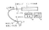
図1は本発明の一実施形態を説明するための歯科用気体レーザ装置の概略構成図であり、図2に基づいて説明した部材と同様な部材には同一符号を付して詳しい説明は省略する。
【0017】
図1において、1は、放電励起が行われて特定波長の気体レーザを生成するレーザ共振器、5は光導波路4の先端に着脱可能に装着されている最先端外径0.4〜1mmの細径チップ、6は細径チップ5を通って被照射体7を冷却するため流出する冷却ガス、8はレーザ共振器1を放電励起する放電励起用電源、9はパルス幅が0.1〜50msでかつデューティ比(パルス幅/周期)が5〜20%のレーザ光パルスにコントロールするためのパルス条件調整手段である。なお、図1においては、電源回りの詳細構造に関する図示を省略してある。
【0018】
図4に示す光導波路の種類の違いによるレーザ光伝送特性からして、レーザ共振器1に炭酸ガスレーザを使用する場合には、光導波路4として銀ハライド系結晶ファイバもしくは中空導波管を用いることがよく、また、レーザ共振器1に一酸化炭素ガスレーザを使用する場合には、光導波路4として銀ハライド系結晶ファイバもしくはカルコゲナイド系ガラスファイバを用いることがよい。
【0019】
図1において、レーザ共振器1から出射されたレーザ光2は、集光レンズ3によって絞られ光導波路4を通って、細径チップ5によって微細な治療部位のみを照射するように規制されて被照射体7方向へ照射レーザ光10として出射する。同時に前記細径チップ5からは冷却ガス6が流出して被照射体7を冷却する。前記レーザ光2は、パルス条件調整手段9によって、後述する理由から、パルス幅が0.1〜50msでかつデューティ比(パルス幅/周期)が5〜20%のレーザ光パルスにコントロールされる。
【0020】
このようにすることによって、微細な治療部位に限定された確実なレーザ照射が行われ、しかも硬組織に近接する歯髄が壊死するおそれのない、安全性の高い歯科治療が可能になる。
【0021】
次に、前記構成の気体レーザ装置の動作を、図5〜図7を参照して、より具体的に説明する。
【0022】
図5は細径チップ5を通って被照射体7に吹き付ける冷却ガス6の流量の影響を示したものであり、照射エネルギ量(J)と照射部下部の温度上昇(deg)との関係例を示している。被照射体7は歯科治療で治療の主対象となる抜歯象牙質であり、冷却ガス6には乾燥空気を用いている。
【0023】
図5において、照射エネルギの増大に伴って、当然、温度が上昇しており、温度上昇を緩やかにして過大な熱影響を避けるためには、毎分1.5リットル以上の冷却ガス流量が必要であることが分かる。また、冷却ガス6の流量が多過ぎても治療部位近傍の付着物等を飛散させるためよくない。
【0024】
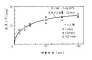
図6はデューティ比(パルス幅/周期)を一定にした場合のパルス幅の影響を、照射時間(sec)と照射部下部の温度上昇(deg)との関係において調べた例を示したものであり、パルス1周期に対する照射時間幅の割合を固定しており、パルス休止時間がパルス幅に比例して長くなっている。しかし、パルス幅が100ms以下の場合、象牙質の温度上昇は、パルス幅,周期に依存せず、略同じであって差が見られない。このため、能率を考慮すれば短時間周期ほど有利となるため、2Hz程度以上が望ましく、デューティ比10%と仮定するとパルス幅は50ms以下となる。
【0025】
一方、生体組織等をレーザ蒸発すると、プラズマが生成されて除去効率が低下するため、短パルスが理論的には有利になる。しかし、本例では上述したように中遠赤外レーザ用に適した光導波路4を用いるため、その耐パルス出力性能を十分考慮する必要がある。一般的には、この種の素材の短パルスに対するレーザ破壊しきい値は概ね数十J/cm2であり、例えばファイバ径が直径0.4mm、かつ入射出力60Wの場合では、安全率を考慮すると、パルス幅は約0.1msが限界となる。
【0026】
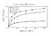
図7はデューティ比を変化させたときの照射エネルギ量(J)と照射部下部の温度上昇(deg)との関係例を示しており、同じ照射エネルギ量であっても温度上昇はデューティ比によって異なる。これはデューティ比が小さい程、休止時間が長いために冷却ガス6が大きく作用して温度上昇が抑制されるためである。そこで、デューティ比は小さな方が望ましいが、効率を考慮すると5〜20%が妥当な範囲となる。
【0027】
なお、従来のレーザ手術装置では、フット・スイッチ等のオン/オフの操作の繰り返しが無制限に行えるため、設定条件のレーザ光を過度に照射する可能性がある。このため、本歯科用気体レーザ装置においては、設定パルス条件に応じてフット・スイッチの連続照射を制限するための手段を設けることが望ましく、このようにすることによって安全性を向上させることができる。
【0028】
【発明の効果】
以上説明したように、本発明の歯科用気体レーザ装置によれば、微細な治療部位に限定した確実なレーザ照射を行うことができ、硬組織に近接する歯髄が壊死する等の悪影響のおそれがない、安全な歯科治療が可能になる。
【図面の簡単な説明】
【図1】本発明の一実施形態を説明するための歯科用気体レーザ装置の概略構成図である。
【図2】従来のレーザ手術装置の概略構成図である。
【図3】レーザ光における波長と水および骨への吸収度との関係例を示す特性曲線図である。
【図4】各種の光導波路のレーザ光伝送特性例を示す特性曲線図である。
【図5】冷却ガス流量と照射エネルギ量と温度上昇との関係例を示す特性曲線図である。
【図6】パルス幅と照射時間と温度上昇との関係例を示す特性曲線図である。
【図7】デューティ比と照射エネルギ量と温度上昇との関係例を示す特性曲線図である。
【符号の説明】
1…レーザ共振器、 2…レーザ光、 3…集光レンズ、 4…光導波路、 5…細径チップ、 6…冷却ガス、 7…被照射体、 8…放電励起用電源、 9…パルス条件調整手段。[0001]
TECHNICAL FIELD OF THE INVENTION
The present invention relates to a dental gas laser device that exerts effects such as evaporation, coagulation, hemostasis, and sterilization by causing laser light to act on hard tissue in the oral cavity.
[0002]
[Prior art]
2. Description of the Related Art In recent years, laser surgical apparatuses have been widely applied to not only surgical operations but also endoscopic operations due to improvements in optical waveguides (from an articulated mirror type to flexible optical fibers). Recently, due to the good results of oral surgery, application to dental hard tissue regions, which had not been approved before, has been actively studied.
[0003]
This type of laser surgical apparatus is generally configured as shown in FIG. 2. A
[0004]
Incidentally, the configuration of the
[0005]
However, as shown in FIG. 3, the laser light of the above-mentioned wavelength has a long penetration depth due to little absorption into water or bone tissue, which is a main component of the living body, and the influence of the laser light on deep tissue which is not visible is large. Easy to receive.
[0006]
For this reason, the most promising medical laser from the practical aspect is a mid-far infrared wavelength laser that efficiently absorbs into water and bones, and a carbon dioxide laser with a wavelength of 10.6 μm, which is the most practically used, Also, carbon monoxide gas having a wavelength of 5.6 μm is regarded as important. In general, a gas laser is excited by a discharge method, and it is difficult in principle to obtain a short pulse such as a solid laser excited by a flash lamp.
[0007]
The discharge-pumped gas laser device was originally developed as a laser capable of extracting continuous oscillation with high output and high efficiency, and the main purpose of the conventional laser surgical device is to efficiently incise and evaporate biological soft tissue. For this reason, a continuous output or a pulse output having a relatively long pulse width (0.1 seconds or more) is often used.
[0008]
At these wavelengths, the silica fiber absorbs light and cannot transmit it, and the development of high-performance optical fibers that can guide high-power lasers has been delayed. Is what is being done.
[0009]
As shown in FIG. 4, for example, silver halide crystals are said to be excellent for laser light having a wavelength of 5 to 15 μm, but their power resistance is only about several tens of watts. Although a thin waveguide made of metal has been studied, there is a problem to be solved in oxidation of the inner surface by irradiation with a laser beam, etc., in addition to slightly inferior flexibility and operability. Such a laser transmission characteristic of the mid-far infrared wavelength is disclosed in, for example, SPIE 1420 (1991), pp. 150-160.
[0010]
[Problems to be solved by the invention]
However, in the configuration of the conventional gas laser device as described above, in the case of treatment of dental hard tissue, the thermal influence on the dental pulp and the like existing in the vicinity of the treatment site becomes excessive, and there is a possibility that they may be necrotic. There is a problem that is high.
[0011]
In other words, the carbon dioxide gas laser and the carbon monoxide gas laser absorb laser light better than the Nd-YAG laser in the living soft tissue, have a very small depth reach, and have no risk of causing adverse effects on the underlying tissue. It has been said that the higher the output of the emitted laser light, the higher the efficiency.
[0012]
For this reason, treatment with pulse output, in which the average output is smaller than in the case of continuous output, is not generally used because of reduced efficiency, and may not be used, especially for short pulses. could not.
[0013]
An object of the present invention is to solve such a conventional problem and to provide a dental gas laser device capable of safely treating dental hard tissue.
[0014]
[Means for Solving the Problems]
In order to achieve the above object, a dental gas laser device of the present invention includes a laser resonator, an optical waveguide that guides a laser beam output from the laser resonator to an irradiation target, and a laser light source attached to a tip of the optical waveguide. a thin chip cutting edge outer diameter of 0.4~1mm the diameter of the laser light is regulatedso as to irradiate the microscopic sites Te,gently to excessive temperature rise of the thin chip as the irradiation object A cooling gasfor coolingto avoid thermal effects , a condenser lens for condensing the laser light on the optical waveguide, and an excitation power supply for discharging and exciting the laser resonator, and a pulse width of 0.1 to 50 ms. And pulse condition adjusting means for controlling the laser light pulse to have a duty ratio (pulse width / period) of 5 to 20%. With this configuration, the mid-far red light output from the laser resonator is provided. Outside laser light is optically guided The laser beam is transmitted through the optical path (optical fiber or hollow waveguide) and guided to the hard tissue to be treated in a narrow oral cavity, and a laser beam is finally emitted. Therefore, reliable irradiation limited to a minute treatment site is performed. Furthermore, by using a laser light pulse having a pulse width of 0.1 to 50 ms and a duty ratio (pulse width / period) of 5 to 20%, there is no adverse effect such as necrosis of the pulp close to hard tissue, and safety. Increase.
[0015]
BEST MODE FOR CARRYING OUT THE INVENTION
Hereinafter, preferred embodiments of the present invention will be described with reference to the drawings.
[0016]
FIG. 1 is a schematic configuration diagram of a dental gas laser device for describing an embodiment of the present invention. Members similar to those described with reference to FIG. I do.
[0017]
In FIG. 1,
[0018]
When a carbon dioxide laser is used for the
[0019]
In FIG. 1, a
[0020]
By doing so, reliable laser irradiation limited to a minute treatment site is performed, and highly safe dental treatment that does not cause necrosis of the pulp close to hard tissue can be performed.
[0021]
Next, the operation of the gas laser device having the above configuration will be described more specifically with reference to FIGS.
[0022]
FIG. 5 shows the influence of the flow rate of the cooling
[0023]
In FIG. 5, the temperature naturally rises as the irradiation energy increases, and a cooling gas flow rate of 1.5 liters per minute or more is required to moderate the temperature rise and avoid an excessive thermal effect. It turns out that it is. Further, even if the flow rate of the cooling
[0024]
FIG. 6 shows an example in which the influence of the pulse width when the duty ratio (pulse width / period) is fixed is examined in relation to the irradiation time (sec) and the temperature rise (deg) at the lower part of the irradiation unit. In addition, the ratio of the irradiation time width to one pulse period is fixed, and the pulse pause time is increased in proportion to the pulse width. However, when the pulse width is 100 ms or less, the temperature rise of the dentin does not depend on the pulse width and the cycle and is substantially the same, and no difference is seen. For this reason, if the efficiency is taken into consideration, the shorter the cycle, the more advantageous it is. Therefore, it is desirable to be about 2 Hz or more, and if the duty ratio is 10%, the pulse width is 50 ms or less.
[0025]
On the other hand, when a living tissue or the like is laser-evaporated, plasma is generated and the removal efficiency is reduced, so that short pulses are theoretically advantageous. However, in this example, as described above, since the
[0026]
FIG. 7 shows an example of the relationship between the irradiation energy amount (J) when the duty ratio is changed and the temperature rise (deg) at the lower part of the irradiation unit. Even when the irradiation energy amount is the same, the temperature rise depends on the duty ratio. different. This is because the smaller the duty ratio, the longer the pause time, and the greater the effect of the cooling
[0027]
In addition, in the conventional laser operation apparatus, since the on / off operation of the foot switch or the like can be repeatedly performed without limitation, there is a possibility that the laser light under the set conditions is excessively irradiated. For this reason, in the present dental gas laser device, it is desirable to provide a means for restricting continuous irradiation of the foot switch according to the set pulse condition, and thus safety can be improved. .
[0028]
【The invention's effect】
As described above, according to the dental gas laser device of the present invention, it is possible to perform reliable laser irradiation limited to a fine treatment site, and there is a possibility of adverse effects such as necrosis of the pulp close to hard tissue. No, safe dental treatment will be possible.
[Brief description of the drawings]
FIG. 1 is a schematic configuration diagram of a dental gas laser device for describing an embodiment of the present invention.
FIG. 2 is a schematic configuration diagram of a conventional laser surgery apparatus.
FIG. 3 is a characteristic curve diagram showing an example of the relationship between the wavelength of laser light and the degree of absorption into water and bone.
FIG. 4 is a characteristic curve diagram showing examples of laser light transmission characteristics of various optical waveguides.
FIG. 5 is a characteristic curve diagram showing an example of a relationship among a cooling gas flow rate, an irradiation energy amount, and a temperature rise.
FIG. 6 is a characteristic curve diagram showing an example of a relationship among a pulse width, an irradiation time, and a temperature rise.
FIG. 7 is a characteristic curve diagram showing an example of a relationship among a duty ratio, an irradiation energy amount, and a temperature rise.
[Explanation of symbols]
DESCRIPTION OF
Claims (6)
Translated fromJapanesePriority Applications (1)
| Application Number | Priority Date | Filing Date | Title |
|---|---|---|---|
| JP19052196AJP3577653B2 (en) | 1996-07-19 | 1996-07-19 | Dental gas laser device |
Applications Claiming Priority (1)
| Application Number | Priority Date | Filing Date | Title |
|---|---|---|---|
| JP19052196AJP3577653B2 (en) | 1996-07-19 | 1996-07-19 | Dental gas laser device |
Publications (2)
| Publication Number | Publication Date |
|---|---|
| JPH1033557A JPH1033557A (en) | 1998-02-10 |
| JP3577653B2true JP3577653B2 (en) | 2004-10-13 |
Family
ID=16259481
Family Applications (1)
| Application Number | Title | Priority Date | Filing Date |
|---|---|---|---|
| JP19052196AExpired - Fee RelatedJP3577653B2 (en) | 1996-07-19 | 1996-07-19 | Dental gas laser device |
Country Status (1)
| Country | Link |
|---|---|
| JP (1) | JP3577653B2 (en) |
Families Citing this family (8)
| Publication number | Priority date | Publication date | Assignee | Title |
|---|---|---|---|---|
| US7769066B2 (en) | 2006-11-15 | 2010-08-03 | Cree, Inc. | Laser diode and method for fabricating same |
| US7834367B2 (en) | 2007-01-19 | 2010-11-16 | Cree, Inc. | Low voltage diode with reduced parasitic resistance and method for fabricating |
| US8519437B2 (en) | 2007-09-14 | 2013-08-27 | Cree, Inc. | Polarization doping in nitride based diodes |
| US9012937B2 (en) | 2007-10-10 | 2015-04-21 | Cree, Inc. | Multiple conversion material light emitting diode package and method of fabricating same |
| JP2009095536A (en)* | 2007-10-18 | 2009-05-07 | Panasonic Corp | Laser therapy device |
| EP2459115A4 (en)* | 2009-07-30 | 2017-03-15 | Nathan Paul Monty | Dental laser system using midrange gas pressure |
| KR101300120B1 (en)* | 2011-04-11 | 2013-08-26 | 주식회사 루트로닉 | laser theraphy apparatus and control method of laser theraphy apparatus |
| JP5849307B2 (en)* | 2011-06-01 | 2016-01-27 | 国立大学法人大阪大学 | Dental treatment device |
- 1996
- 1996-07-19JPJP19052196Apatent/JP3577653B2/ennot_activeExpired - Fee Related
Also Published As
| Publication number | Publication date |
|---|---|
| JPH1033557A (en) | 1998-02-10 |
Similar Documents
| Publication | Publication Date | Title |
|---|---|---|
| KR100434195B1 (en) | Surgical laser device and its use method | |
| US5290274A (en) | Laser apparatus for medical and dental treatments | |
| Nelson et al. | Ablation of bone and methacrylate by a prototype mid‐infrared erbium: YAG laser | |
| US6554824B2 (en) | Methods for laser treatment of soft tissue | |
| US5401171A (en) | Dental laser device and method | |
| US4925523A (en) | Enhancement of ultraviolet laser ablation and etching organic solids | |
| US5820627A (en) | Real-time optical feedback control of laser lithotripsy | |
| US20130177865A1 (en) | System and Method for Performing Endodontic Procedures with Lasers | |
| WO1996028212A1 (en) | Laser surgical device and method of its use | |
| US20090281531A1 (en) | Interventional and therapeutic electromagnetic energy systems | |
| KR20110106861A (en) | Laser-Induced Vapor / Plasma-Mediated Medical Treatment Methods and Apparatus | |
| US20210000567A1 (en) | Dental laser for the treatment of soft tissue | |
| Sulieman | An overview of the use of lasers in general dental practice: 1. Laser physics and tissue interactions | |
| JP3577653B2 (en) | Dental gas laser device | |
| US20060127861A1 (en) | Laser apparatus for treating hard tissues and method for using the apparatus | |
| RU2113827C1 (en) | Surgical laser device and method for applying it | |
| US6050991A (en) | Pulsed-emission laser for use in the medical field | |
| Yeragi et al. | LASER physics & its application in dentistry-a review | |
| Tafoya et al. | Efficient and compact high-power mid-IR (~ 3 um) lasers for surgical applications | |
| WO2008072033A1 (en) | A surgical apparatus and a method for treating biological hard tissues, particularly for dental surgery, based on a fibre laser | |
| Pankratov et al. | Comparative laser-tissue interaction effects at 1.96 and 2.01 um of Cr; Tm: YAG laser | |
| KR100508979B1 (en) | Erbium yag laser apparatus | |
| Frank | Biophysical fundamentals for laser application in medicine | |
| EP0626229A1 (en) | Solid state laser for removing physiologic tissue | |
| Auth | Laser photocoagulation principles |
Legal Events
| Date | Code | Title | Description |
|---|---|---|---|
| A977 | Report on retrieval | Free format text:JAPANESE INTERMEDIATE CODE: A971007 Effective date:20040115 | |
| A131 | Notification of reasons for refusal | Free format text:JAPANESE INTERMEDIATE CODE: A131 Effective date:20040330 | |
| A521 | Written amendment | Free format text:JAPANESE INTERMEDIATE CODE: A523 Effective date:20040528 | |
| TRDD | Decision of grant or rejection written | ||
| A01 | Written decision to grant a patent or to grant a registration (utility model) | Free format text:JAPANESE INTERMEDIATE CODE: A01 Effective date:20040629 | |
| A61 | First payment of annual fees (during grant procedure) | Free format text:JAPANESE INTERMEDIATE CODE: A61 Effective date:20040701 | |
| R150 | Certificate of patent or registration of utility model | Free format text:JAPANESE INTERMEDIATE CODE: R150 | |
| FPAY | Renewal fee payment (event date is renewal date of database) | Free format text:PAYMENT UNTIL: 20070723 Year of fee payment:3 | |
| FPAY | Renewal fee payment (event date is renewal date of database) | Free format text:PAYMENT UNTIL: 20080723 Year of fee payment:4 | |
| FPAY | Renewal fee payment (event date is renewal date of database) | Free format text:PAYMENT UNTIL: 20090723 Year of fee payment:5 | |
| FPAY | Renewal fee payment (event date is renewal date of database) | Free format text:PAYMENT UNTIL: 20090723 Year of fee payment:5 | |
| FPAY | Renewal fee payment (event date is renewal date of database) | Free format text:PAYMENT UNTIL: 20100723 Year of fee payment:6 | |
| FPAY | Renewal fee payment (event date is renewal date of database) | Free format text:PAYMENT UNTIL: 20110723 Year of fee payment:7 | |
| FPAY | Renewal fee payment (event date is renewal date of database) | Free format text:PAYMENT UNTIL: 20110723 Year of fee payment:7 | |
| FPAY | Renewal fee payment (event date is renewal date of database) | Free format text:PAYMENT UNTIL: 20120723 Year of fee payment:8 | |
| FPAY | Renewal fee payment (event date is renewal date of database) | Free format text:PAYMENT UNTIL: 20120723 Year of fee payment:8 | |
| FPAY | Renewal fee payment (event date is renewal date of database) | Free format text:PAYMENT UNTIL: 20130723 Year of fee payment:9 | |
| S111 | Request for change of ownership or part of ownership | Free format text:JAPANESE INTERMEDIATE CODE: R313113 | |
| S533 | Written request for registration of change of name | Free format text:JAPANESE INTERMEDIATE CODE: R313533 | |
| R350 | Written notification of registration of transfer | Free format text:JAPANESE INTERMEDIATE CODE: R350 | |
| S111 | Request for change of ownership or part of ownership | Free format text:JAPANESE INTERMEDIATE CODE: R313113 | |
| R350 | Written notification of registration of transfer | Free format text:JAPANESE INTERMEDIATE CODE: R350 | |
| S111 | Request for change of ownership or part of ownership | Free format text:JAPANESE INTERMEDIATE CODE: R313113 | |
| R350 | Written notification of registration of transfer | Free format text:JAPANESE INTERMEDIATE CODE: R350 | |
| LAPS | Cancellation because of no payment of annual fees |