JP3577374B2 - Magnetic recording / reproducing device - Google Patents
Magnetic recording / reproducing deviceDownload PDFInfo
- Publication number
- JP3577374B2 JP3577374B2JP23879795AJP23879795AJP3577374B2JP 3577374 B2JP3577374 B2JP 3577374B2JP 23879795 AJP23879795 AJP 23879795AJP 23879795 AJP23879795 AJP 23879795AJP 3577374 B2JP3577374 B2JP 3577374B2
- Authority
- JP
- Japan
- Prior art keywords
- view
- connector
- chassis
- magnetic recording
- spring
- Prior art date
- Legal status (The legal status is an assumption and is not a legal conclusion. Google has not performed a legal analysis and makes no representation as to the accuracy of the status listed.)
- Expired - Fee Related
Links
Images


Description
Translated fromJapanese【0001】
【産業上の利用分野】
本発明は磁気記録再生装置に係り、さらに詳しくは、磁気記録再生装置に付設されたコネクタに対して外部コネクタを簡単に接続できるようにした、コネクタの接続構造に関する。
【0002】
【従来の技術】
ディスクカートリッジに内蔵された磁気ディスクに対して情報の記録再生を行うようにした磁気記録再生装置では、磁気記録再生装置をコンピュータ本体等の外部機器に組み込んだ状態で、磁気記録再生装置に付設されたコネクタに外部機器に付設された外部コネクタを接続する必要がある。
【0003】
従来より、このような磁気記録再生装置において、互いに接合・一体化されて筐体を形成する上下一対のカバーの内部に、メカニズム本体とプリント基板等を収納し、両カバーの前面にディスクカートリッジの挿入口を設けたものが知られている。前記メカニズム本体はディスクカートリッジのローディング機構やステッピングモータを駆動源とするヘッド移送機構等から構成され、これらはシャーシ上に載置されている。また、前記プリント基板はシャーシの下面に固定され、このプリント基板にはメカニズム本体の駆動用回路部品やコネクタが実装されている。
【0004】
前記メカニズム本体とプリント基板は組立途中でユニット化され、このユニット体を挾むように上下両カバーを接合・一体化することにより、磁気記録再生装置は両カバーで覆われた状態で組立てられる。その際、プリント基板に実装されたコネクタは、両カバーの後端接合部分に形成される開口の内部に位置する。そして、磁気記録再生装置をコンピュータ本体等の外部機器に組み込んだ状態で、外部機器の外部コネクタを両カバーの後端開口から挿入してプリント基板上のコネクタに連結することにより、磁気記録再生装置と外部機器とが電気的に接続される。
【0005】
【発明が解決しようとする課題】
ところで、前述した従来の磁気記録再生装置では、ユニット化されたメカニズム本体とプリント基板を一対のカバーで上下方向から覆うようになっており、両カバーの奥行き寸法を内部のユニット体よりも大きくする必要があるため、装置全体の軽量化や材料の削減化が両カバーによって妨げられるという問題があった。また、両カバーを接合・一体化した後に、ヘッド移送機構の駆動源であるステッピングモータの取付位置を微調整することがあるが、従来の磁気記録再生装置では、ステッピングモータが両カバーの後端開口の内部に配設されているため、この調整作業が面倒であるという問題もあった。
【0006】
そこで、上カバーの奥行き寸法を下カバーよりも短寸とし、コネクタとステッピングモータを上カバーから露出させることが考えられる。この場合、コネクタとステッピングモータの上方を覆っていた上カバーの一部が削除されるため、その分だけ上カバーの材料を削減できると共に、ステッピングモータの調整作業も広い空間内で簡単に行うことができる。しかしながら、コネクタの周囲が開放空間となるため、外部コネクタをコネクタに挿入する際の位置決め基準がなくなり、外部コネクタの接続作業が面倒になるという新たな問題が発生する。
【0007】
本発明は、このような従来技術の実情ならびに要望に鑑みてなされたもので、その目的は、軽量化や材料削減化を図りつつ、外部コネクタをコネクタに簡単に接続することが可能な磁気記録再生装置を提供することにある。
【0008】
【課題を解決するための手段】
上記目的を達成するために、本発明は、互いに接合・一体化されて筐体を形成する上下一対のカバーと、これら上カバーと下カバー内に収納されたメカニズム本体と、このメカニズム本体の駆動用回路部品やコネクタが実装されたプリント基板とを備え、前記上カバーの奥行き寸法を前記下カバーに対して短寸にすることにより、該下カバーの後端部上方を開放し、この開放部分から前記コネクタを露出させ、かつ、前記下カバーの後端に前記コネクタに接続される外部コネクタの横方向の移動を規制する規制壁を形成したことを、最も主要な特徴としている。
【0009】
また、上記の構成において、ヘッド移送機構の駆動源であるモータを前記コネクタと共に前記開放部分から露出させることが好ましく、さらに、前記規制壁を前記コネクタの左右両側に対向する位置にそれぞれ形成しても良い。
【0010】
【作用】
上下一対のカバーが接合・一体化された状態で、メカニズム本体やプリント基板の大部分は両カバーによって覆われているが、プリント基板に実装されたコネクタは下カバーの後端部上方の開放部分に位置し、上カバーによって覆われていない。そして、外部コネクタをコネクタに接続する場合、外部コネクタは下カバーの後端に形成された規制壁によって横ズレが規制されるため、外部コネクタをコネクタに簡単に接続することができる。
また、下カバーの後端部上方の開放部分に、ヘッド移送機構の駆動源であるモータをコネクタと共に露出させた場合、モータの調整作業を簡単に行うことができる。さらに、コネクタの左右両側に対応して、下カバーの後端に複数の規制壁を形成した場合、外部コネクタの横ズレを一層確実に防止することができる。
【0011】
【実施例】
以下、本発明の実施例を図に基づいて説明する。
図1〜図47は本発明の一実施例を説明するもので、図1は磁気記録再生装置の平面図、図2は該磁気記録再生装置の正面図、図3は該磁気記録再生装置の背面図、図4は該磁気記録再生装置の側面図、図5はディスクカートリッジの平面図、図6は図1から上カバーを取り除いて示す平面図、図7はその背面図、図8はその側面図、図9は図6からホルダを取り除いて示す平面図、図10はシャーシの平面図、図11は該シャーシの側面図、図12は該シャーシのガイド突起と突部を示す斜視図、図13はスライド板の平面図、図14は該スライド板の背面図、図15は該スライド板の側面図、図16はシャーシとスライド板の係合状態を示す断面図、図17はホルダの平面図、図18は該ホルダの背面図、図19は該ホルダの側面図、図20は該ホルダを母材から外形抜きする状態を示す説明図、図21はシャッタ開閉機構の要部を示す斜視図である。
【0012】
図1〜図4に示すように、本実施例に係る磁気記録再生装置は、互いに接合・一体化されて筐体を形成する上カバー1および下カバー2と、これら上・下カバー1,2の内部に収納されたメカニズム本体と、上・下カバー1,2の前方の開口に取付けられた前面板3とで構成されている。前面板3には横長形状の挿入口3aが穿設されると共に、後述するイジェクト釦4が出入可能に配設されている。また、前面板3の裏側には扉5が回動可能に支承されており、この扉5は図示せぬコイルバネによって挿入口3aを閉塞する方向に付勢されている。
【0013】
上記磁気記録再生装置に用いられるディスクカートリッジ6は公知のもので、図5に示すように、硬質プラスチックで成形されたカートリッジケース7と、このカートリッジケース7の内部に回転自在に収納された磁気ディスク8と、カートリッジケース7の一側縁に沿って往復移動可能なシャッタ9とで構成されている。カートリッジケース7の一隅はテーパ状に切り落されており、当該個所が誤挿入防止部7aとなっている。シャッタ9はコの字状に折り曲げられており、その上下両面に長方形の窓孔9aが形成され、カートリッジケース7にもこれら窓孔9aに対応する開口7bが形成されている。このシャッタ9は図示せぬバネによって開口7bを閉鎖する方向へ付勢されているが、ディスクカートリッジ6が前面板3の挿入口3aから内部に挿入されると、後述するシャッタ開閉機構によって開口7bと窓孔9aとが一致する方向へ移動され、これら開口7bと窓孔9aから磁気ディスク8が露出するようになっている。
【0014】
図6〜図9に示すように、前記メカニズム本体は、下カバー2の上面に固定されたシャーシ10と、このシャーシ10上面に前後進可能に載置されたスライド板11と、このスライド板11に保持されたホルダ12等で構成されている。以下、これらシャーシ10とスライド板11およびホルダ12の具体的構成について説明する。
【0015】
前記シャーシ10は、母材である鉄板の上下両面に亜鉛メッキを施したものが用いられている。図10〜図12に示すように、このシャーシ10の前後両端には起立壁10a,10bがそれぞれ折り曲げ形成されており、前方の起立壁10aの近傍に円形孔10cが穿設されている。円形孔10cの周囲にはL字形状をなす複数のガイド突起10dが底面に対して直角に折り曲げ形成されており、このガイド突起10dはシャーシ10の片側について2個ずつ、左右両側で4個形成されている。シャーシ10の底面には複数の突部10eが上方に向けて突出形成されており、これら突部10eは各ガイド突起10dの近傍、好ましくは10mm以内に配置されている。各突部10eはシャーシ10を板厚方向にプレス加工することによって形成され、前述したように、シャーシ10には予め亜鉛メッキが施されているため、各突部10eは表面に亜鉛メッキが施された平坦面を有することになる。また、シャーシ10の底面には複数の補強用リブ10fが形成されると共に、前記ディスクカートリッジ6の下降位置を規定する2つのストッパ突起10gや、後方の起立壁10bと所定間隔を存して対向する支持壁10h等が折り曲げ形成されている。さらに、シャーシ10の左右両側面には切欠き10iが形成され、後方の起立壁10bにはねじ孔10jが形成されている。
【0016】
前記スライド板11も前記シャーシ10と同様に、母材である鉄板の上下両面に亜鉛メッキを施したものが用いられている。図13〜図15に示すように、このスライド板11は断面U状に折り曲げ形成されており、その底面中央に開口11aが穿設されている。また、スライド板11の前後端には取付片11bと係止爪11cとがそれぞれ折り曲げ形成されており、この取付片11bに前記イジェクト釦4が取付けられるようになっている。さらに、スライド板11の底面には複数のガイド孔11dと1つの挿通孔11fが穿設されており、スライド板11の側面には片側について2個ずつ、左右両側で4個のカム溝11eが形成されている。このスライド板11は各ガイド孔11dを前記ガイド突起10dと一方のストッパ突起10gに挿入し、他方のストッパ突起10gを挿通孔11fに挿入した状態で前記シャーシ10上に載置され、各ガイド孔11dが対応するガイド突起10dによって上下方向と左右方向に位置規制されることにより、シャーシ10の前後方向にのみ移動できるようになっている(図9参照)。その際、図16に示すように、スライド板11の下面はシャーシ10に形成された突部10eの上面を摺動し、これらスライド板11の下面と突部10eの上面には共に亜鉛メッキが施されているため、スライド板11をシャーシ10に対して滑らかに摺動させることができる。
【0017】
前記ホルダ12も前記シャーシ10やスライド板11と同様に、母材である鉄板の上下両面に亜鉛メッキを施したものが用いられている。図17〜図19に示すように、このホルダ12は断面逆U状に折り曲げ形成されており、その両側面の下端にホルダ12の上面と所定間隔を存して対向する支持片12aが折り曲げ形成されている。ホルダ12の上面には上方に若干膨らんだ膨出部12bが形成されており、この膨出部12bには前後方向に延びる長孔12cと円弧状の逃孔12dとが形成されている。膨出部12bの近傍には抜け止め突起12eが折り曲げ形成されると共に、係止孔12fが穿設されている。また、ホルダ12の上面前端にはストッパ突片12gが形成されており、このストッパ突片12gの幅寸法W1は長孔12cの幅寸法W2以下(W1≦W2)に設定されている。さらに、ホルダ12の側面には片側について2個ずつ、左右両側で4個の突起12hが形成されると共に、下方へ延びる垂下片12iが形成されている。
【0018】
図20に示すように、前記ホルダ12は平板状の母材(亜鉛メッキを施した鉄板)を外形抜きした後、これに折り曲げ加工等を施すことにより、前述の如き形状にフォーミングされる。かかる外形抜き時に、ストッパ突片12gの幅寸法W1と長孔12cの幅寸法W2との関係がW1≦W2に設定されているため、任意のホルダ12に形成されるストッパ突片12gを別のホルダ12に形成される長孔12c内に位置させることにより、母材から生じるスクラップを極力少なくすることができる。すなわち、凹状の長孔12cを外形抜きする際に母材に残る凸状部分は本来スクラップとして廃棄されるものであるが、当該部分を別のホルダ12のストッパ突片12gとして利用できるため、母材の無駄分を少なくすることができる。
【0019】
図6〜図9に戻り、前記ホルダ12は前記スライド板11の両側面間に挿入され、ホルダ12の上面とスライド板11の一側面との間には引っ張りばね13が掛合されている。ここで、ホルダ12の垂下片12iはスライド板11の底面を貫通して前記シャーシ10の切欠き10i内に挿入され、これら垂下片12iと切欠き10iとの係合によりホルダ12はシャーシ10に対して上下方向にのみ移動できるよう規制されており、一方、前述したように、スライド板11はシャーシ10の前後方向にのみ移動可能であるため、スライド板11は引っ張りばね13によってシャーシ10の前端方向へ付勢されている。また、スライド板11とホルダ12の後方には回動部材14が配置されており、この回動部材14はシャーシ10に植設された支軸15に回転可能に支承され、捩じりコイルばね16によって図6の反時計回り方向に付勢されている。
【0020】
前記回動部材14はプラスチックの成形材からなり、図21に示すように、この回動部材14は、支軸15に挿入される筒状の軸部14aと、この軸部14aから側方へ突出する一対の腕部14b,14cとを有している。軸部14aの上端には鉤形をなす一対の支持壁14d,14eが形成されており、これら支持壁14d,14eの周囲に前記捩じりコイルばね16が巻回されている。その際、両支持壁14d,14e間に軸線方向に延びる一対のスリット14fが形成され、かつ、一方の支持壁14eが他方の支持壁14fよりも厚肉に形成されているため、薄肉側の支持壁14eを撓めることにより、捩じりコイルばね16の巻回部分を両支持壁14d,14e間に容易に挿入できるようになっている。また、一方の腕部14bの先端にはシャッタ開閉ピン14gが立設されており、このシャッタ開閉ピン14gは前記逃孔12dを貫通してホルダ12の上方に達し、該シャッタ開閉ピン14gに前記捩じりコイルばね16の一端が掛止されている。さらに、他方の腕部14cの先端にはロック爪14hが形成されており、このロック爪14hは前記スライド板11の係止爪11cと係脱可能である。なお、捩じりコイルばね16の他端は前記ホルダ12の抜け止め突起12eを通り、その先端に形成された折曲部16aが係止孔12fに掛止されている。
【0021】
図22はヘッド移送機構の平面図、図23は該ヘッド移送機構の断面図、図24は該ヘッド移送機構に備えられるキャリッジの平面図、図25は該キャリッジの裏面図、図26は該キャリッジの背面図、図27は図25のA−A線に沿う断面図、図28は該キャリッジへフォロワばねを取付ける状態を示す説明図、図29は該キャリッジのヘッド取付部を示す斜視図、図30は該キャリッジと下側磁気ヘッドの取付け状態を長手方向から見た断面図、図31はその短手方向から見た断面図、図32は該ヘッド移送機構に備えられるホールドケースの平面図、図33は該ホールドケースとキャリッジの取付け部分を示す要部平面図、図34は図33のB−B線に沿う断面図である。
【0022】
前記シャーシ10の後部にはヘッド移送機構17が配置されており、図22,23に示すように、このヘッド移送機構17はキャリッジ18と該キャリッジ18の上方にヒンジ結合されたホールドケース19とで構成されている。これらキャリッジ18とホールドケース19は共にプラスチック材で成形されており、キャリッジ18の上面には下側磁気ヘッド20が、ホールドケース19の下面には上側磁気ヘッド21がそれぞれ固定されている。
【0023】
図24〜図27に示すように、前記キャリッジ18の後部には段付状の連結部18aが形成されており、この連結部18aの上面には、円形溝18b、ねじ孔18c、規制突部18d、一対の位置決めピン18e、ばね受部18f、L字状のばね支持部18g等が形成されている。また、前記連結部18aの裏側には、下面を開放した凹部18hと、該凹部18hを介して対向する一対の支持部18iと、凹部18hに向かって傾斜するガイド部18jとが形成されており、一方の支持部18iにはねじ孔18kと位置決めピン18lが設けられている。前記両支持部18iの下面はほぼ同一平面を形成し、これら支持部18i間に2点鎖線で示すフォロワばね22が固定されるようになっている。
【0024】
このフォロワばね22の取付けに際しては、図28に示すように、まず、前記キャリッジ18を逆さにした状態で、フォロワばね22を連結部18aの裏側から両支持部18i上に落とし込み、該フォロワばね22の位置決め孔22aを位置決めピン18lに挿入する。しかる後、ねじ23をフォロワばね22の透孔22bを挿通してねじ孔18kに螺入し、該ねじ23を締め付けることにより、フォロワばね22はキャリッジ18の連結部18a裏面に取付固定される。その際、凹部18hの開口端にはガイド部18jが形成されているため、フォロワばね22は該ガイド部18jに沿って両支持部18i上に確実に落とし込まれ、フォロワばね22を簡単に取付けることができる。
【0025】
図22〜図27に戻り、前記キャリッジ18の一側部には貫通孔18mが形成されており、この貫通孔18mが前記シャーシ10に固定されたガイドシャフト24に挿通されることにより、キャリッジ18はシャーシ10の前後方向に案内されている。また、キャリッジ18の他側部にはL字状腕18nが形成されており、このL字状腕18nはスクリューシャフト25の上方を通り、シャーシ10上に配設されたフォトインタラプタ等からなる検出部26まで達している。前記L字状腕18nの裏面には凸部18oが刻設されており、この凸部18oは前記フォロワばね22の弾発力を受けてスクリューシャフト25と螺合している。前記スクリューシャフト25は前記シャーシ10の後方の起立壁10bに取付けられたステッピングモータ27の回転軸であり、該スクリューシャフト25の先端はシャーシ10の前記支持壁10hに軸支されている。したがって、ステッピングモータ27を駆動源としてスクリューシャフト25が回転すると、該スクリューシャフト25の回転が凸部18oを介してキャリッジ18に伝達され、該キャリッジ18がシャーシ10の前後方向、すなわち、前記磁気ディスク8の半径方向へ移動される。また、その際に、L字状腕18nの先端が検出部26を横切ると、ゼロトラック信号が出力される。
【0026】
図29〜図31に示すように、前記キャリッジ18の先端中央部には取付台18pが形成されており、この取付台18pの周囲は窪み部18qとなっている。取付台18pの上面にはキャリッジ18の長手方向に延びる接着剤充填溝18rと、該接着剤充填溝18rを介して対向する逃げ溝18sとが形成され、該取付台18pの両側部には貫通孔18tが形成されており、前記接着剤充填溝18rの一端は他の部分に比べて幅寸法が大きい円形の幅広部となっている。このように構成された取付台18p上には前記下側磁気ヘッド20が載置され、該下側磁気ヘッド20は前記接着剤充填溝18rに充填された接着剤28によって取付台18pに固定されている。その際、接着剤充填溝18rの一端に形成された円形の幅広部は下側磁気ヘッド20より外方に位置しており、この幅広部から注入された接着剤28は接着剤充填溝18rを通って下側磁気ヘッド20と取付台18pとの間に確実に充填される。また、接着剤充填溝18rは下側磁気ヘッド20の下面中央に沿って延びているため、下側磁気ヘッド20は取付台18pに対してバランス良く接着固定される。さらに、下側磁気ヘッド20は薄肉コア部20aと厚肉コア部20bとを有しているが、厚肉コア部20bに比べて剛性の低い薄肉コア部20aは、接着剤充填溝18rを跨いで両逃げ溝18s上に位置し、接着剤充填溝18rから下側磁気ヘッド20の下面を通って流出する余剰の接着剤28がこれら逃げ溝18s内に溜められるようになっている。その結果、薄肉コア部20aと取付台18pとの接触面積が少なくなるため、薄肉コア部20aが接着剤28の硬化によって破損することが防止される。
【0027】
なお、接着剤28によって下側磁気ヘッド20を取付台18pに固定した後、必要に応じて、下側磁気ヘッド20の周囲にUV樹脂等の接着剤29を塗布すると、下側磁気ヘッド20は取付台18pに一層確実に固定される(図30参照)。そして、このようにキャリッジ18の取付台18p上に接着固定された下側磁気ヘッド20はFPC(フレキシブルプリント基板)30に接続され、該FPC30は前記窪み部18qを通って後述するプリント基板まで導かれるようになっている。
【0028】
図32に示すように、前記ホールドケース19の上面にはばね受部19aが形成されると共に、その両側部には第1支持腕19bと第2支持腕19cとが突出形成されている。第1支持腕19bの下面は第2支持腕19cの下面に対して低い位置にあり、本実施例の場合、第1支持腕19bの先端を下方へ向けてL字状に形成することにより、第1支持腕19bの先端が第2支持腕19cより下方へ突出するようになっている。また、ホールドケース19の後端部には弾性金属板からなるリーフヒンジばね31が設けられており、これらホールドケース19とリーフヒンジばね31はアウトサート成形によって一体化されている。さらに、ホールドケース19の先端部にはジンバルばねを介して前記上側磁気ヘッド21が固定されており、この上側磁気ヘッド21も図示省略したFPCを介して後述するプリント基板まで導かれるようになっている。
【0029】
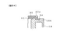
このように構成されたホールドケース19は、図22,23に示すように、前記キャリッジ18の連結部18a上にリーフヒンジばね31と取付板32とを重ね合わせて載置した後、上方から止めねじ33を連結部18aのねじ孔18cに螺入することにより、キャリッジ18の連結部18a上にヒンジ結合される。その際、図26に示すように、リーフヒンジばね31の一側縁をキャリッジ18のばね支持部18gの基部に形成された切り込み18u内に挿通して連結部18aに載置することにより、該ばね支持部18gによってリーフヒンジばね31の一側縁が押さえられている。この状態で、ホールドケース19を止めねじ33の締付力に抗して微小回転し、下側磁気ヘッド20と上側磁気ヘッド21のアライメントを調整した後、キャリッジ18の円形溝18bに接着剤34を充填することにより、リーフヒンジばね31が連結部18aに仮固定される。この場合、図33,34に示すように、リーフヒンジばね31は円形溝18bをほぼ半分だけ覆うように連結部18aに載置されるため、該円形溝18bの露出部分から接着剤34をキャリッジ18とリーフヒンジばね31との間に容易に充填することができる。また、リーフヒンジばね31の取付板32に切欠き32aが形成されているため、余剰の接着剤34は該切欠き32a内に溜められ、接着剤34の不所望なはみ出しが防止される。なお、上記仮固定が終了した後、止めねじ33を強く締め付けて本固定されるが、この場合、リーフヒンジばね31は接着剤34によって連結部18aに仮固定されているため、下側磁気ヘッド20と上側磁気ヘッド21のアライメントは維持される。
【0030】
前記取付板32は金属平板をプレス抜きすることによって形成されたものであり、該プレス抜きの際に取付板32の一方の面にバリが発生する。このバリの高さは不均一であり、仮りに、バリが発生した面を裏にして取付板32をキャリッジ18の連結部18aに載置した場合、止めねじ33の締付力がリーフヒンジばね31に均一に作用しなくなる。そこで、本実施例では、図22に示すように、取付板32の一隅に切り落とし部32cを形成し、この切り落とし部32c内に前記キャリッジ18の規制突部18dを位置させることにより、取付板32に方向性を持たせてある。したがって、取付板32をキャリッジ18の連結部18aに載置した状態では、常にバリが上を向くようになり、取付板32を逆にした状態でキャリッジ18に組み込めないようになっている。
【0031】
再び図22に戻り、前記キャリッジ18のばね支持部18gにはロードスプリング35の巻回部分が挿入されており、該ロードスプリング35の両自由端をばね受部18f,19aにそれぞれ掛止することにより、ホールドケース19はキャリッジ18に向けて弾性付勢されている。前記ロードスプリング35は捩じりコイルばねからなり、その巻回部分から両自由端までの長さl1,l2はほぼ等しい長さに設定されている。このため、ロードスプリング35を組み込む際に、その向きを気にする必要がなくなり、作業性の向上が図られている。また、ホールドケース19は前記ホルダ12の長孔12c内に位置しており、該ホールドケース19に設けられた2つの支持腕19b,19cのうち、第1支持腕19bはロードスプリング35の弾発力を受けてホルダ12の膨出部12bと当接し、第2支持腕19cと膨出部12b間には所定のクリアランスが確保されている。その際、第1支持腕19bに対して第2支持腕19cがリーフヒンジばね31から遠い位置に形成されているため、第2支持腕19cと膨出部12b間に必要とされるクリアランスを確保した上で、第2支持腕19cの厚さ寸法を可及的に大きくすることができるようになっている。さらに、第1支持腕19bはガイドシャフト24のほぼ真上でホルダ12の膨出部12bと当接し、該ガイドシャフト24から離れた位置でヘッド移送機構17がフォロワばね22によって弾性的に支持されているため、ばね力が小さいフォロワばね22を用いても、キャリッジ18を含むヘッド移送機構17の浮き上がりを防止することができる。
【0032】
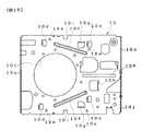
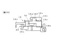
図35は前記シャーシを裏側から見た図であり、同図に示すように、シャーシ10の下面にはサブシャーシ36と前述したプリント基板37とが固定されている。サブシャーシ36上にはスピンドルモータ38が搭載されており(図9参照)、このスピンドルモータ38は制御基板やFPCを介してプリント基板37と電気的に接続されている。プリント基板37には前記ステッピングモータ27やスピンドルモータ38等の駆動回路用素子等を含む回路素子が実装されると共に、図9に示すように、その上面後端部には2つのコネクタ39,40が取付けられている。これらコネクタ39,40は複数の接続ピン39a,40aを有する雄コネクタであり、2点鎖線で示す外部機器の雌コネクタ41をこれらコネクタ39,40に挿入することにより、磁気記録再生装置は外部機器に接続されるようになっている。
【0033】
図36は前記上カバーの平面図、図37は該上カバーの背面図、図38は該上カバーの側面図、図39は前記下カバーの平面図、図40は該下カバーの背面図、図41は該下カバーの側面図である。
【0034】
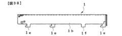
図36〜図38に示すように、前記上カバー1は平板状の天面2aと該天面1aの両側縁から垂下する一対の側面1bおよび天面1aの後端から垂下する背面1cとを有し、これら側面1bと背面1cは天面1aに対して直角に折り曲げ形成されている。背面1cには透孔1dが形成され、一方の側面1bの下端にはL字状をなす脚片1eが2個、他方の側面1bの下端にはL字状をなす脚片1eと角形の垂下片1fが1個ずつ形成されている。これら脚片1eと垂下片1fの形成位置は互いに上カバー1の前後方向に位置ずれしており、したがって、上カバー1を金属平板の母材から多数個取りする際に、任意の上カバー1に形成される脚片1eや垂下片1fを、別の上カバー1に形成される両脚片1e間または脚片1eと垂下片1f間に位置させることにより、母材から生じるスクラップを極力少なくすることができる。
【0035】
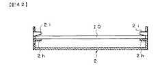
図39〜図41に示すように、前記下カバー2は平板状の底面2aと該底面2aの両側縁から起立する一対の側面2bおよび底面2aの後端から起立する背面2cとを有し、これら側面2bと背面2cは底面2aに対して直角に折り曲げ形成されている。下カバー2の底面2aの奥行き寸法は前記上カバー1の天面2aの奥行き寸法より大きく設定されており、上カバー1はその短寸分だけ材料の削減と軽量化が図られている。また、背面2cの高さ寸法は各側面2bに対して十分に小さく設定されており、該背面2cの上端には一対の規制壁2dが突設されている。一方の側面2bには2個の係止片2eが形成され、他方の側面2bには1個の係止片2eと透孔2fを有する折り曲げ片2gが形成されている。これら係止片2eは垂直線に沿って側面2bの内方へ略直角に折り曲げ形成されたものである。また、各側面2bには開口を介して対向する支持片2hと止片2iの組が、片側について2組ずつ左右両側で4組形成されている。各組における支持片2hと止片2iは上下方向に位置ずれしており、止片2iの下端は上方へ向かって傾斜している。該止片2iはプレス抜きされた状態であるが、支持片2hはプレス抜き後に垂直線に沿って側面2bの内方へ略直角に折り曲げられている。
【0036】
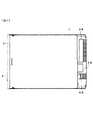
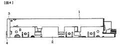
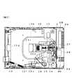
このように構成された下カバー2に対して前記メカニズム本体を固定した後、下カバー2に上カバー1を被せて両者1,2を互いに接合・一体化することにより、前述の如く、磁気記録再生装置の筐体が形成される。この場合、図42に示すように、まず、組立が完了したメカニズム本体のシャーシ10を下カバー2の内部に挿入して各支持片2h上に載置した後、各止片2iを側面2bの内方へ略直角に折り曲げ、それぞれの止片2iと支持片2hの組でシャーシ10を挾持する。図6〜図8はこの状態を示すものであり、これらの図から明らかなように、プリント基板37上に取付けられたコネクタ39,40の側方に下カバー2の規制壁2dが位置する。
【0037】
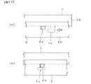
次いで、図43(a)に示すように、下カバー2の両側面2bの内側に上カバー1の両側面1bを挿入し、上カバー1を下カバー2の後端方向(矢印方向)に押し込むと、図43(b)に示すように、上カバー1の側面1b下端と各脚片1eの先端との間に下カバー2の対応する各係止片2eが入り込み、上カバー1が下カバー2に結合される。この場合、脚片1eとそこに係止される係止片2eは上カバー1や下カバー2の母材をプレス抜きしたものであるから、いずれも高い寸法精度が確保されており、したがって、各係止片2eの折り曲げ角度にかかわらず、各脚片1eは対応する係止片2eに確実に係止される。また、係止片2eをプレス抜きした際に形成される開口が脚片1eによって塞がれるため、防塵や磁気シールドが図られている。しかる後、図44に示すように、ねじ42を上カバー1と下カバー2の透孔1d,2fを挿通してシャーシ10のねじ孔10jに螺入すると、シャーシ10を含むメカニズム本体と下カバー2および上カバー1の三者が互いに接合・一体化される。
【0038】
図1〜図4はこの状態を示すものであり、これらの図から明らかなように、メカニズム本体の大部分は上下カバー1,2によって覆われるが、プリント基板37上に取付けられたコネクタ39,40と、シャーシ10の起立壁10bに取付けられたステッピングモータ26とは、上カバー1の後端から外方へ露出し、下カバー2の後端部上方の開放部分に位置している。また、前述したように、下カバー2の背面2cに形成された両規制壁2dが各コネクタ39,40の側方に位置する。したがって、外部機器の雌コネクタ41をこれらコネクタ39,40に挿入する際、雌コネクタ41は規制壁2dによって横方向のズレが規制され、雌コネクタ41をコネクタ39,40に対して容易に挿入することができる。さらに、ステッピングモータ26の取付位置を調整する必要が生じた場合は、この調整作業をステッピングモータ26の上方の広い空間を利用して行うことができる。
【0039】
本実施例に係る磁気記録再生装置は上記したように構成されており、次に、その動作について説明する。
【0040】
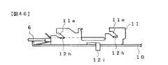
ディスクカートリッジ6の未装着状態において、回動部材14は捩じりコイルばね16に弾性付勢されて図6の位置にあり、該回動部材14のロック爪14hがスライド板11の係止爪11cに係合することにより、スライド板11は後退位置に保たれている。この場合、図45に示すように、ホルダ12の各突起12hはスライド板11の各カム溝11eの上端に係止され、ホルダ12は上昇位置に保たれている。
【0041】
ディスクカートリッジ6を前面板3の挿入口3aから内部に挿入すると、ディスクカートリッジ6によって扉5が回動されるが、この扉5の過度の回動はホルダ12のストッパ突片12gと当接することにより規制される。ディスクカートリッジ6をさらに挿入し、ホルダ12の上面と支持片12aとの間を通って回動部材14のシャッタ開閉ピン14gに突き当てると、その挿入途中で、捩じりコイルばね16の折曲部16aはテーパ状の誤挿入防止部7aによって外方へ逃がされる。なお、ディスクカートリッジ6の天地を逆にして誤挿入した場合は、カートリッジケース7の先端が折曲部16aに当接するため、ディスクカートリッジ6をそれ以上挿入することができないようになっている。
【0042】
さらに、ディスクカートリッジ6を内部に挿入すると、図47に示すように、回動部材14は捩じりコイルばね16の弾性力に抗して図6の時計回り方向に回転し、ディスクカートリッジ6の先端部分はヘッド移送機構17のキャリッジ18とホールドケース19との間に入り込む。そして、この回動部材14の回転に伴い、シャッタ開閉ピン14gがホルダ12の透孔12d内を回動するため、該シャッタ開閉ピン14gによってシャッタ9が移動され、カートリッジケース7内の磁気ディスク8が開口7bと窓孔9aから露出する。また、前記回動部材14の回転に伴い、ロック爪14hと係止爪11cの係止が解除されるため、スライド板11が引っ張りばね13によって前進位置へ移動され、スライド板11の取付板11cに固定されたイジェクト釦4が前面板3から突出する。その結果、図45に示すように、ホルダ12の各突起12hがスライド板11の各カム溝11eの下端へ移動し、ホルダ12はディスクカートリッジ6と共に下降位置、すなわち、ローディング位置へと移動する。また、ホルダ12の膨出部12bに第1支持腕19bが当接しているため、ホルダ12の下降に伴い、ロードスプリング35に付勢されたホールドケース19も下降し、キャリッジ18側の下側磁気ヘッド20とホールドケース19側の上側磁気ヘッド21がそれぞれ磁気ディスク8に接触する。ここで、ホルダ12の膨出部12bに当接するのは第1支持腕19bのみであり、その反力がリーフヒンジばね31に捩じりモーメントとして作用するが、前述したように、リーフヒンジばね31の一側縁がばね支持部18gの切り込み18uによって押さえられているため、リーフヒンジばね31の変形が防止されている。なお、万が一、落下等によって大きな外力が作用した場合は、ホールドケース19の第2支持腕19cがホルダ12の膨出部12bに衝当するため、両磁気ヘッド20,21が衝突して破損しないようになっている。
【0043】
このようにしてディスクカートリッジ6がローディング位置まで移動された後、ステッピングモータ27を駆動してスクリューシャフト25を回転させると、該スクリューシャフト25の回転がねじ部18oを介してキャリッジ18に伝達され、ヘッド移送機構17はガイドシャフト24に沿って磁気ディスク8の半径方向へ移動する。また、スピンドルモータ38を駆動することにより磁気ディスク8が回転し、該磁気ディスク8に対して下側磁気ヘッド20および上側磁気ヘッド21から情報の記録/再生が行われる。
【0044】
また、ローディング位置にあるディスクカートリッジ6を排出する場合は、前面板3より突出するイジェクト釦4を押圧し、スライド板11を引っ張りばね13の弾性力に抗して後退位置へ移動する。すると、ホルダ12は図46のローディング位置から図45に示すアンローディング位置へと上昇し、図47の反時計回り方向に回動する回動部材14によって、ディスクカートリッジ6が前面板3の挿入口3aから排出されると共に、回動部材14のロック爪14hがスライド板11の係止爪11cに係止することにより、スライド板11が再び後退位置に保たれる。
【0045】
なお、本発明は上記実施例に限定されず、コネクタ39,40や規制壁2dの数を含め、種々の変形例を採用することが可能である。例えば、図48に示すように、下カバー2に形成される規制壁2dの数を増加し、これら規制壁2dを各コネクタ39,40の左右両側に位置させることも可能であり、この場合は、外部機器の雌コネクタ41の横ズレを一層確実に防止することができる。
【0046】
【発明の効果】
以上説明したように、本発明によれば、上カバーの奥行き寸法を下カバーに比べて短寸にした分だけ、軽量化や材料削減化が図れるばかりでなく、外部コネクタをコネクタに接続する場合、外部コネクタは下カバーの後端に形成された規制壁によって横ズレが規制されるため、外部コネクタをコネクタに簡単に接続することができる。また、下カバーの後端部上方の開放部分に、ヘッド移送機構の駆動源であるモータをコネクタと共に露出させた場合、モータの調整作業を簡単に行うことができ、さらに、規制壁をコネクタの左右両側に対応して複数形成した場合、外部コネクタの横ズレを一層確実に防止することができる。
【図面の簡単な説明】
【図1】本発明の一実施例に係る磁気記録再生装置の平面図である。
【図2】該磁気記録再生装置の正面図である。
【図3】該磁気記録再生装置の背面図である。
【図4】該磁気記録再生装置の側面図である。
【図5】ディスクカートリッジの平面図である。
【図6】図1から上カバーを取り除いて示す平面図である。
【図7】その背面図である。
【図8】その側面図である。
【図9】図6からホルダを取り除いて示す平面図である。
【図10】該磁気記録再生装置に備えられるシャーシの平面図である。
【図11】該シャーシの側面図である。
【図12】該シャーシのガイド突起と突部を示す斜視図である。
【図13】該磁気記録再生装置に備えられるスライド板の平面図である。
【図14】該スライド板の背面図である。
【図15】該スライド板の側面図である。
【図16】該スライド板とシャーシの係合状態を示す断面図である。
【図17】該磁気記録再生装置に備えられるホルダの平面図である。
【図18】該ホルダの背面図である。
【図19】該ホルダの側面図である。
【図20】該ホルダを母材から外形抜きする状態を示す説明図である。
【図21】該磁気記録再生装置に備えられるシャッタ開閉機構の要部を示す斜視図である。
【図22】該磁気記録再生装置に備えられるヘッド移送機構の平面図である。
【図23】該ヘッド移送機構の断面図である。
【図24】該ヘッド移送機構に備えられるキャリッジの平面図である。
【図25】該キャリッジの裏面図である。
【図26】該キャリッジの背面図である。
【図27】図25のA−A線に沿う断面図である。
【図28】該キャリッジへフォロワばねを取付ける状態を示す説明図である。
【図29】該キャリッジのヘッド取付部を示す斜視図である。
【図30】該キャリッジと下側磁気ヘッドの取付け状態を長手方向から見た断面図である。
【図31】その短手方向から見た断面図である。
【図32】該ヘッド移送機構に備えられるホールドケースの平面図である。
【図33】該ホールドケースとキャリッジの取付け部分を示す要部平面図である。
【図34】図33のB−B線に沿う断面図である。
【図35】図10のシャーシを裏側から見た図である。
【図36】該磁気記録再生装置に備えられる上カバーの平面図である。
【図37】該上カバーの背面図である。
【図38】該上カバーの側面図である。
【図39】該磁気記録再生装置に備えられる下カバーの平面図である。
【図40】該下カバーの背面図である。
【図41】該下カバーの側面図である。
【図42】該下カバーとシャーシの固定関係を示す説明図である。
【図43】上カバーと下カバーの組立工程を示す説明図である。
【図44】上カバーと下カバーおよびシャーシの固定部分を示す要部断面図である。
【図45】アンローディング時のホルダとスライド板の関係を示す説明図である。
【図46】ローディング時のホルダとスライド板の関係を示す説明図である。
【図47】図6のローディング状態を示す平面図である。
【図48】本発明の他の実施例に係る磁気記録再生装置の背面図である。
【符号の説明】
1 上カバー
1e 脚片
2 下カバー
2e 係止片
2h 支持片
2i 止片
5 扉
6 ディスクカートリッジ
7 カートリッジケース
7a 誤挿入防止部
8 磁気ディスク
9 シャッタ
10 シャーシ
10d ガイド突起
10e 突部
11 スライド板
11c 係止爪
11d ガイド孔
11e カム溝
12 ホルダ
12c 長孔
12f 係止孔
12g ストッパ突片
12h 突起
13 引っ張りばね
14 回動部材
14a 軸部
14b,14c 腕部
14d,14e 支持壁
14f スリット
14g シャッタ開閉ピン
14h ロック爪
16 捩じりコイルばね
16a 折曲部
17 ヘッド移送機構
18 キャリッジ
18a 連結部
18b 円形溝
18c,18k ねじ孔
18d 規制突部
18e,18l 位置決めピン
18f ばね受部
18g ばね支持部
18h 凹部
18i 支持部
18j ガイド部
18p 取付台
18q 窪み部
18r 接着剤充填溝
18s 逃げ溝
18u 切り込み
19 ホールドケース
19a ばね受部
19b 第1支持腕
19c 第2支持腕
20 下側磁気ヘッド
20a 薄肉コア部
20b 厚肉コア部
21 上側磁気ヘッド
22 フォロワばね
23 ねじ
24 ガイドシャフト
25 スクリューシャフト
27 ステッピングモータ
28 接着剤
31 リーフヒンジばね
32 取付板
32a 切欠き
32c 切り落とし部
33 止めねじ
34 接着剤
35 ロードスプリング
37 プリント基板
39,40 コネクタ
41 雌コネクタ
42 ねじ[0001]
[Industrial applications]
The present invention relates to a magnetic recording / reproducing device, and more particularly, to a connector connection structure that allows an external connector to be easily connected to a connector attached to the magnetic recording / reproducing device.
[0002]
[Prior art]
In a magnetic recording / reproducing apparatus configured to record and reproduce information on a magnetic disk built in a disk cartridge, the magnetic recording / reproducing apparatus is attached to an external device such as a computer main body, and is attached to the magnetic recording / reproducing apparatus. It is necessary to connect the external connector attached to the external device to the connector.
[0003]
Conventionally, in such a magnetic recording / reproducing apparatus, a mechanism body and a printed circuit board are housed inside a pair of upper and lower covers which are joined and integrated with each other to form a housing, and a disk cartridge is mounted on the front of both covers. A device provided with an insertion port is known. The mechanism body includes a loading mechanism of a disk cartridge, a head transfer mechanism driven by a stepping motor, and the like, and these are mounted on a chassis. The printed circuit board is fixed to the lower surface of the chassis, and a drive circuit component and a connector of the mechanism body are mounted on the printed circuit board.
[0004]
The mechanism body and the printed circuit board are unitized during assembly, and the upper and lower covers are joined and integrated so as to sandwich the unit body, so that the magnetic recording / reproducing apparatus is assembled with both covers. At this time, the connector mounted on the printed circuit board is located inside the opening formed at the rear end joining portion of both covers. Then, in a state where the magnetic recording / reproducing device is incorporated in an external device such as a computer main body, an external connector of the external device is inserted from a rear end opening of both covers and connected to a connector on a printed circuit board, thereby obtaining a magnetic recording / reproducing device. And the external device are electrically connected.
[0005]
[Problems to be solved by the invention]
By the way, in the above-described conventional magnetic recording / reproducing apparatus, the unitized mechanism body and the printed circuit board are covered from above and below by a pair of covers, and the depth dimension of both covers is made larger than the internal unit body. Because of the necessity, there is a problem that the weight reduction of the entire apparatus and the reduction of materials are hindered by both covers. Also, after the two covers are joined and integrated, the mounting position of the stepping motor, which is the drive source of the head transfer mechanism, may be finely adjusted. There is also a problem that this adjustment work is troublesome because the adjustment work is arranged inside the opening.
[0006]
Therefore, it is conceivable to make the depth dimension of the upper cover shorter than that of the lower cover and expose the connector and the stepping motor from the upper cover. In this case, a part of the upper cover that covers the upper part of the connector and the stepping motor is deleted, so that the material of the upper cover can be reduced by that much, and the adjustment of the stepping motor can be easily performed in a wide space. Can be. However, since the periphery of the connector is an open space, there is no positioning reference when the external connector is inserted into the connector, and a new problem occurs in that the connection work of the external connector becomes troublesome.
[0007]
The present invention has been made in view of such circumstances and demands of the prior art, and has as its object to reduce the weight and material consumption, and to make it possible to easily connect an external connector to a connector. A playback device is provided.
[0008]
[Means for Solving the Problems]
In order to achieve the above object, the present invention provides a pair of upper and lower covers joined and integrated with each other to form a housing, a mechanism body housed in the upper cover and the lower cover, and a driving mechanism for the mechanism body. A printed circuit board on which circuit parts and connectors are mounted, and by making the depth of the upper cover shorter than that of the lower cover, the upper part of the lower cover is opened at the rear end and the open part is opened. The most main feature is that the connector is exposed from the rear cover and a regulating wall is formed at the rear end of the lower cover to regulate a lateral movement of an external connector connected to the connector.
[0009]
Further, in the above configuration, it is preferable that a motor that is a drive source of a head transfer mechanism is exposed from the open portion together with the connector, and furthermore, the regulating walls are formed at positions facing both right and left sides of the connector. Is also good.
[0010]
[Action]
With the upper and lower covers joined and integrated, most of the mechanism body and the printed circuit board are covered by both covers, but the connector mounted on the printed circuit board is an open part above the rear end of the lower cover. Located and not covered by the top cover. When the external connector is connected to the connector, the lateral displacement of the external connector is regulated by the regulating wall formed at the rear end of the lower cover, so that the external connector can be easily connected to the connector.
In addition, when the motor, which is the drive source of the head transfer mechanism, is exposed together with the connector at the open portion above the rear end of the lower cover, the operation of adjusting the motor can be easily performed. Furthermore, when a plurality of regulating walls are formed at the rear end of the lower cover corresponding to the left and right sides of the connector, lateral displacement of the external connector can be prevented more reliably.
[0011]
【Example】
Hereinafter, embodiments of the present invention will be described with reference to the drawings.
1 to 47 illustrate an embodiment of the present invention. FIG. 1 is a plan view of a magnetic recording / reproducing apparatus, FIG. 2 is a front view of the magnetic recording / reproducing apparatus, and FIG. 4 is a side view of the magnetic recording / reproducing apparatus, FIG. 5 is a plan view of a disk cartridge, FIG. 6 is a plan view of the disk cartridge with the upper cover removed from FIG. 1, FIG. 7 is a rear view thereof, and FIG. FIG. 9 is a plan view showing the chassis with the holder removed, FIG. 10 is a plan view of the chassis, FIG. 11 is a side view of the chassis, FIG. 12 is a perspective view showing guide projections and projections of the chassis, 13 is a plan view of the slide plate, FIG. 14 is a rear view of the slide plate, FIG. 15 is a side view of the slide plate, FIG. 16 is a cross-sectional view showing an engagement state between the chassis and the slide plate, and FIG. FIG. 18 is a rear view of the holder, FIG. 19 is a side view of the holder, and FIG. 0 is an explanatory view showing a state in which the outer shape punching the holder from the base material. FIG. 21 is a perspective view showing a main portion of the shutter opening and closing mechanism.
[0012]
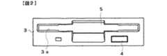
As shown in FIGS. 1 to 4, the magnetic recording / reproducing apparatus according to the present embodiment includes an
[0013]
The
[0014]
As shown in FIGS. 6 to 9, the mechanism body includes a
[0015]
The
[0016]
Similarly to the
[0017]
Like the
[0018]
As shown in FIG. 20, the
[0019]
Referring back to FIGS. 6 to 9, the
[0020]
The turning
[0021]
22 is a plan view of the head transfer mechanism, FIG. 23 is a cross-sectional view of the head transfer mechanism, FIG. 24 is a plan view of a carriage provided in the head transfer mechanism, FIG. 25 is a rear view of the carriage, and FIG. 27 is a cross-sectional view taken along line AA of FIG. 25, FIG. 28 is an explanatory view showing a state where a follower spring is mounted on the carriage, and FIG. 29 is a perspective view showing a head mounting portion of the carriage. 30 is a cross-sectional view of the mounting state of the carriage and the lower magnetic head viewed from the longitudinal direction, FIG. 31 is a cross-sectional view of the carriage from the short direction, FIG. 32 is a plan view of a hold case provided in the head transfer mechanism, FIG. 33 is a plan view of a main part showing a mounting portion of the hold case and the carriage, and FIG. 34 is a cross-sectional view taken along line BB of FIG.
[0022]
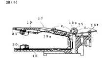
A
[0023]
As shown in FIGS. 24 to 27, a stepped connecting portion 18a is formed at the rear portion of the
[0024]
When the
[0025]
Returning to FIG. 22 to FIG. 27, a through
[0026]
As shown in FIGS. 29 to 31, a mounting base 18p is formed at the center of the distal end of the
[0027]
After the lower
[0028]
As shown in FIG. 32, a spring receiving portion 19a is formed on the upper surface of the
[0029]
22 and 23, the
[0030]
The mounting
[0031]
Returning to FIG. 22, the winding portion of the
[0032]
FIG. 35 is a view of the chassis viewed from the rear side. As shown in FIG. 35, a
[0033]
36 is a plan view of the upper cover, FIG. 37 is a rear view of the upper cover, FIG. 38 is a side view of the upper cover, FIG. 39 is a plan view of the lower cover, FIG. 40 is a rear view of the lower cover, FIG. 41 is a side view of the lower cover.
[0034]
As shown in FIGS. 36 to 38, the
[0035]
As shown in FIGS. 39 to 41, the
[0036]
After the mechanism main body is fixed to the
[0037]
Next, as shown in FIG. 43 (a), the both sides 1b of the
[0038]
FIGS. 1 to 4 show this state. As is clear from these figures, most of the mechanism body is covered by the upper and
[0039]
The magnetic recording / reproducing apparatus according to the present embodiment is configured as described above, and the operation will be described next.
[0040]
When the
[0041]
When the
[0042]
Further, when the
[0043]
After the
[0044]
When ejecting the
[0045]
The present invention is not limited to the above embodiment, and various modifications including the number of
[0046]
【The invention's effect】
As described above, according to the present invention, when the depth dimension of the upper cover is made shorter than that of the lower cover, not only the weight and material can be reduced, but also the case where the external connector is connected to the connector. Since the lateral displacement of the external connector is regulated by the regulating wall formed at the rear end of the lower cover, the external connector can be easily connected to the connector. In addition, when the motor, which is the drive source of the head transfer mechanism, is exposed together with the connector at the open portion above the rear end of the lower cover, the adjustment work of the motor can be easily performed, and the regulating wall can be attached to the connector. When a plurality is formed corresponding to both left and right sides, lateral displacement of the external connector can be prevented more reliably.
[Brief description of the drawings]
FIG. 1 is a plan view of a magnetic recording / reproducing apparatus according to an embodiment of the present invention.
FIG. 2 is a front view of the magnetic recording / reproducing apparatus.
FIG. 3 is a rear view of the magnetic recording / reproducing apparatus.
FIG. 4 is a side view of the magnetic recording / reproducing apparatus.
FIG. 5 is a plan view of the disk cartridge.
FIG. 6 is a plan view showing an upper cover removed from FIG. 1;
FIG. 7 is a rear view thereof.
FIG. 8 is a side view thereof.
FIG. 9 is a plan view showing a state where a holder is removed from FIG. 6;
FIG. 10 is a plan view of a chassis provided in the magnetic recording / reproducing apparatus.
FIG. 11 is a side view of the chassis.
FIG. 12 is a perspective view showing a guide projection and a projection of the chassis.
FIG. 13 is a plan view of a slide plate provided in the magnetic recording / reproducing apparatus.
FIG. 14 is a rear view of the slide plate.
FIG. 15 is a side view of the slide plate.
FIG. 16 is a sectional view showing an engagement state between the slide plate and a chassis.
FIG. 17 is a plan view of a holder provided in the magnetic recording / reproducing apparatus.
FIG. 18 is a rear view of the holder.
FIG. 19 is a side view of the holder.
FIG. 20 is an explanatory diagram showing a state where the outer shape of the holder is removed from the base material.
FIG. 21 is a perspective view showing a main part of a shutter opening / closing mechanism provided in the magnetic recording / reproducing apparatus.
FIG. 22 is a plan view of a head transfer mechanism provided in the magnetic recording / reproducing apparatus.
FIG. 23 is a sectional view of the head transfer mechanism.
FIG. 24 is a plan view of a carriage provided in the head transfer mechanism.
FIG. 25 is a rear view of the carriage.
FIG. 26 is a rear view of the carriage.
FIG. 27 is a sectional view taken along the line AA of FIG.
FIG. 28 is an explanatory diagram showing a state in which a follower spring is mounted on the carriage.
FIG. 29 is a perspective view showing a head mounting portion of the carriage.
FIG. 30 is a cross-sectional view of the mounting state of the carriage and the lower magnetic head as viewed from the longitudinal direction.
FIG. 31 is a cross-sectional view as viewed from the lateral direction.
FIG. 32 is a plan view of a hold case provided in the head transfer mechanism.
FIG. 33 is a main part plan view showing a mounting portion of the hold case and the carriage.
34 is a sectional view taken along line BB of FIG.
FIG. 35 is a view of the chassis of FIG. 10 as viewed from the back side.
FIG. 36 is a plan view of an upper cover provided in the magnetic recording / reproducing apparatus.
FIG. 37 is a rear view of the upper cover.
FIG. 38 is a side view of the upper cover.
FIG. 39 is a plan view of a lower cover provided in the magnetic recording / reproducing device.
FIG. 40 is a rear view of the lower cover.
FIG. 41 is a side view of the lower cover.
FIG. 42 is an explanatory view showing a fixed relationship between the lower cover and a chassis.
FIG. 43 is an explanatory view showing an assembling step of the upper cover and the lower cover.
FIG. 44 is an essential part cross-sectional view showing a fixed portion of the upper cover, the lower cover, and the chassis.
FIG. 45 is an explanatory diagram showing the relationship between the holder and the slide plate during unloading.
FIG. 46 is an explanatory diagram showing the relationship between the holder and the slide plate during loading.
FIG. 47 is a plan view showing the loading state of FIG. 6;
FIG. 48 is a rear view of a magnetic recording / reproducing apparatus according to another embodiment of the present invention.
[Explanation of symbols]
1 Top cover
1e leg piece
2 Lower cover
2e Locking piece
2h support piece
2i tab
5 door
6 disk cartridge
7 Cartridge case
7a Mis-insertion prevention part
8 Magnetic disk
9 Shutter
10 Chassis
10d guide projection
10e protrusion
11 Slide plate
11c Locking claw
11d guide hole
11e cam groove
12 Holder
12c long hole
12f Lock hole
12g stopper projection
12h protrusion
13 Extension spring
14 Rotating member
14a Shaft
14b, 14c arm
14d, 14e Support wall
14f slit
14g shutter open / close pin
14h lock claw
16 Torsion coil spring
16a bending part
17 Head transfer mechanism
18 Carriage
18a Connecting part
18b circular groove
18c, 18k screw hole
18d regulation protrusion
18e, 18l Positioning pin
18f Spring receiving part
18g spring support
18h recess
18i support
18j Guide part
18p mounting base
18q hollow
18r adhesive filling groove
18s relief groove
18u notch
19 Hold case
19a Spring receiving part
19b first support arm
19c Second support arm
20 Lower magnetic head
20a Thin core
20b thick core
21 Upper magnetic head
22 Follower spring
23 screws
24 Guide shaft
25 Screw shaft
27 Stepper motor
28 adhesive
31 leaf hinge spring
32 Mounting plate
32a notch
32c cut-off part
33 Set screw
34 adhesive
35 Road Spring
37 Printed circuit board
39, 40 connector
41 female connector
42 screws
Claims (3)
Translated fromJapanese前記上カバーの奥行き寸法を前記下カバーに対して短寸にすることにより、該下カバーの後端部上方を開放し、この開放部分から前記コネクタを露出させ、かつ、前記下カバーの後端に前記コネクタに接続される外部コネクタの横方向の移動を規制する規制壁を形成したことを特徴とする磁気記録再生装置。A pair of upper and lower covers joined and integrated with each other to form a housing, a mechanism body housed in the upper cover and the lower cover, and a printed circuit board on which the driving circuit components and connectors of the mechanism body are mounted; With
By making the depth dimension of the upper cover shorter than that of the lower cover, the upper portion of the lower cover is opened above the rear end, the connector is exposed from this open portion, and the rear end of the lower cover is formed. A magnetic recording / reproducing apparatus, further comprising a regulating wall for regulating a lateral movement of an external connector connected to the connector.
Priority Applications (5)
| Application Number | Priority Date | Filing Date | Title |
|---|---|---|---|
| JP23879795AJP3577374B2 (en) | 1995-09-18 | 1995-09-18 | Magnetic recording / reproducing device |
| US08/710,223US5748404A (en) | 1995-09-18 | 1996-09-13 | Magnetic recording/reproducing device with chassis support structure |
| KR1019960040371AKR100256629B1 (en) | 1995-09-18 | 1996-09-17 | Magnetic recording reproducer |
| US08/907,573US5859747A (en) | 1995-09-18 | 1997-08-07 | Cover structure for magnetic recording and reproducing device |
| US08/908,637US5875068A (en) | 1995-09-18 | 1997-08-07 | Magnetic recording/reproducing device with retaining structure for engaging a top cover and bottom cover |
Applications Claiming Priority (1)
| Application Number | Priority Date | Filing Date | Title |
|---|---|---|---|
| JP23879795AJP3577374B2 (en) | 1995-09-18 | 1995-09-18 | Magnetic recording / reproducing device |
Publications (2)
| Publication Number | Publication Date |
|---|---|
| JPH0982080A JPH0982080A (en) | 1997-03-28 |
| JP3577374B2true JP3577374B2 (en) | 2004-10-13 |
Family
ID=17035437
Family Applications (1)
| Application Number | Title | Priority Date | Filing Date |
|---|---|---|---|
| JP23879795AExpired - Fee RelatedJP3577374B2 (en) | 1995-09-18 | 1995-09-18 | Magnetic recording / reproducing device |
Country Status (1)
| Country | Link |
|---|---|
| JP (1) | JP3577374B2 (en) |
- 1995
- 1995-09-18JPJP23879795Apatent/JP3577374B2/ennot_activeExpired - Fee Related
Also Published As
| Publication number | Publication date |
|---|---|
| JPH0982080A (en) | 1997-03-28 |
Similar Documents
| Publication | Publication Date | Title |
|---|---|---|
| US5875068A (en) | Magnetic recording/reproducing device with retaining structure for engaging a top cover and bottom cover | |
| JP3404443B2 (en) | Magnetic recording / reproducing device | |
| JP3264801B2 (en) | Head transfer mechanism of magnetic recording / reproducing device | |
| JP3577374B2 (en) | Magnetic recording / reproducing device | |
| JP3214539B2 (en) | Head transfer mechanism of magnetic recording / reproducing device | |
| JP3589252B2 (en) | Head transfer mechanism of magnetic recording / reproducing device | |
| JP3614216B2 (en) | Magnetic recording / reproducing device | |
| JP3352451B2 (en) | Head transfer mechanism of magnetic recording / reproducing device | |
| JP3408902B2 (en) | Magnetic recording / reproducing device | |
| JPH0982011A (en) | Head transferring mechanism of magnetic recording/ reproducing device | |
| JPH0982003A (en) | Magnetic recording/reproducing device | |
| US20010010610A1 (en) | Thin floppy disk drive capable of preventing an eject lever from erroneously operating | |
| JP2908434B1 (en) | Floppy disk device | |
| JPH0982012A (en) | Head transferring mechanism of magnetic recording/ reproducing device | |
| JP2593537B2 (en) | Disk unit | |
| US4853806A (en) | Apparatus for regulating the force rendered to a magnetic disc by a magnetic head in a rotary magnetic disc device | |
| JP3299897B2 (en) | Head drive mechanism for disk drive | |
| US6795276B2 (en) | Flexible disk drive having a support plate coupled to a pedestal on the main plate by a plurality of projections and a screw | |
| JPH056599Y2 (en) | ||
| JP2907735B2 (en) | Cassette loading device | |
| US6499210B2 (en) | Method of accurately and easily mounting a drive motor to a frame member in assembling a disk drive for driving a flexible disk | |
| JP3322645B2 (en) | Cassette loading mechanism | |
| JPS61204860A (en) | magnetic recording and reproducing device | |
| JPH1064226A (en) | Removable disk cartridge | |
| JPH0822660A (en) | Magnetic tape driving device |
Legal Events
| Date | Code | Title | Description |
|---|---|---|---|
| TRDD | Decision of grant or rejection written | ||
| A01 | Written decision to grant a patent or to grant a registration (utility model) | Free format text:JAPANESE INTERMEDIATE CODE: A01 Effective date:20040706 | |
| A61 | First payment of annual fees (during grant procedure) | Free format text:JAPANESE INTERMEDIATE CODE: A61 Effective date:20040712 | |
| R150 | Certificate of patent or registration of utility model | Free format text:JAPANESE INTERMEDIATE CODE: R150 | |
| FPAY | Renewal fee payment (event date is renewal date of database) | Free format text:PAYMENT UNTIL: 20070716 Year of fee payment:3 | |
| FPAY | Renewal fee payment (event date is renewal date of database) | Free format text:PAYMENT UNTIL: 20080716 Year of fee payment:4 | |
| FPAY | Renewal fee payment (event date is renewal date of database) | Free format text:PAYMENT UNTIL: 20080716 Year of fee payment:4 | |
| FPAY | Renewal fee payment (event date is renewal date of database) | Free format text:PAYMENT UNTIL: 20090716 Year of fee payment:5 | |
| LAPS | Cancellation because of no payment of annual fees |