JP3576720B2 - Dial operating device - Google Patents
Dial operating deviceDownload PDFInfo
- Publication number
- JP3576720B2 JP3576720B2JP27243196AJP27243196AJP3576720B2JP 3576720 B2JP3576720 B2JP 3576720B2JP 27243196 AJP27243196 AJP 27243196AJP 27243196 AJP27243196 AJP 27243196AJP 3576720 B2JP3576720 B2JP 3576720B2
- Authority
- JP
- Japan
- Prior art keywords
- knob
- light
- dial
- knob dial
- turning
- Prior art date
- Legal status (The legal status is an assumption and is not a legal conclusion. Google has not performed a legal analysis and makes no representation as to the accuracy of the status listed.)
- Expired - Fee Related
Links
- 238000001514detection methodMethods0.000description19
- 230000002093peripheral effectEffects0.000description13
- 238000007664blowingMethods0.000description12
- 230000001105regulatory effectEffects0.000description6
- 229920003002synthetic resinPolymers0.000description6
- 239000000057synthetic resinSubstances0.000description6
- 210000000078clawAnatomy0.000description3
- 238000005192partitionMethods0.000description3
- 238000010586diagramMethods0.000description2
- 230000000694effectsEffects0.000description2
- 238000005286illuminationMethods0.000description2
- 238000007511glassblowingMethods0.000description1
- 230000003287optical effectEffects0.000description1
Images


Classifications
- H—ELECTRICITY
- H01—ELECTRIC ELEMENTS
- H01H—ELECTRIC SWITCHES; RELAYS; SELECTORS; EMERGENCY PROTECTIVE DEVICES
- H01H19/00—Switches operated by an operating part which is rotatable about a longitudinal axis thereof and which is acted upon directly by a solid body external to the switch, e.g. by a hand
- H01H19/02—Details
- H01H19/025—Light-emitting indicators
Landscapes
- Rotary Switch, Piano Key Switch, And Lever Switch (AREA)
- Switch Cases, Indication, And Locking (AREA)
Description
Translated fromJapanese【0001】
【発明の属する技術分野】
本発明は、ノブダイアルに設けられた複数の表示部を選択的に照明することに伴い、ノブダイアルの回動位置を報知する構成のダイアル操作装置に関する。
【0002】
【発明が解決しようとする課題】
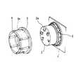
図7は、上記ダイアル操作装置の従来構成を示すものである。ここで、プリント配線基板1にはノブベース2が固定されており、このノブベース2の外周面にはノブダイアル3が回動可能に装着される。このノブダイアル3は、直線状をなす複数の光通路3aを有するものであり、ノブダイアル3には、各光通路3aの一端部に位置して透光性を有する表示部4が設けられている。
【0003】
プリント配線基板1には、表示部4の回動軌跡上に位置して複数の光源5が実装されており、ノブダイアル3をノブベース2の外周面に沿って回動操作すると、ノブダイアル3の回動位置に応じた所定の光源5に電源が供給され、所定の光通路3aを通して所定の表示部4に光が供給される。すると、所定の表示部4が照明され、ノブベース2の複数のマーク2aを選択的に支持することに伴い、ノブダイアル3の回動状態を報知する。
【0004】
しかしながら、上記従来構成では、ノブダイアル3が中間位置(表示部4と光源5とが対向していない位置)にある場合、光源5からの投射光がノブダイアル3により遮断され、表示部4に供給されない。このため、ノブダイアル3の回動途中で、全ての表示部4に対して光の供給が不十分になることがあった。
【0005】
本発明は上記事情に鑑みてなされたものであり、その目的は、ノブダイアルの回動途中でも表示部を極力照明することができるダイアル操作装置を提供することである。
【0006】
【課題を解決するための手段】
請求項1記載のダイアル操作装置は、回動操作可能なノブダイアルと、このノブダイアルに設けられ透光性を有する複数の表示部と、これら複数の表示部の回動軌跡上に配置された複数の光源と、これら複数の光源のうち前記ノブダイアルの回動位置に応じたものを選択的に点灯させる制御装置と、前記ノブダイアルに設けられ前記光源から投射された光を前記表示部に供給する複数の光通路とを備え、これら各光通路が、出光口から入光口に向って幅寸法が大きくなる略扇形状をなしているところに特徴を有する。
【0007】
上記手段によれば、光通路が略扇形状をなし、光通路の幅寸法が出光口から入光口に向って大きくなっている。このため、ノブダイアルが中間位置にある場合でも、光通路相互間に位置する壁部が光源に対向する一瞬を除いて、光源からの投射光が入光口内に投射され、光通路を通して表示部に供給されるので、表示部が極力照明されるようになる。
【0008】
請求項2記載のダイアル操作装置は、ノブダイアルの回動操作が開始されると、制御装置が、ノブダイアルの回動位置に応じた光源を点灯させたまま次の回動位置に応じた光源を点灯させるところに特徴を有する。
【0009】
上記手段によれば、ノブダイアルの回動操作が開始されると、ノブダイアルの回動位置に応じた光源,次の回動位置に応じた光源が点灯し、次の回動位置に応じた光源からの投射光が光通路を通して表示部に供給される。このため、ノブダイアルの次の回動位置に応じた表示部が照明されるようになるので、ノブダイアルの回動方向が報知される。
【0010】
【発明の実施の形態】
以下、本発明の第1実施例を図1ないし図5に基づいて説明する。尚、本実施例は、本発明を自動車のヒータコントローラに適用したものであり、このヒータコントローラはインストルメントパネルに装着されている。まず、図3において、ベゼル32は合成樹脂からなるものであり、後面が開口する矩形箱状をなしている。そして、ベゼル32にはプリント配線基板12がねじ止めされており、ベゼル32の後面開口部は、プリント配線基板12およびカバー11により覆われている。
【0011】
プリント配線基板12の前面には、図5に示すように、合成樹脂製のホルダー13,13が取付けられている。これら各ホルダー13は、図1に示すように、6つの仕切壁13aを一体に有するものであり(4つのみ図示する)、仕切壁13a相互間にはLED収納部13bが区画形成されている。
【0012】
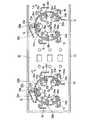
プリント配線基板12の前面には、図4に示すように、円弧状をなす2つのコモン回路パターン14が形成されている。そして、各ホルダー13の5つのLED収納部13b内には、図2および図5に示すように、光源に相当するLED15a〜15eが収納されており、これらLED15a〜15eの一方の端子はコモン回路パターン14に接続されている。
【0013】
プリント配線基板12の前面には、図4に示すように、各コモン回路パターン14の外周部に位置して5つの電源回路パターン16が形成されている。そして、LED15a〜15eの他方の端子は電源回路パターン16に接続されており、各LED15a〜15eには、コモン回路パターン14および電源回路パターン16を通して電源が供給される。
【0014】
図5に示すノブベース17,17は合成樹脂により形成されたものであり、各ノブベース17には筒部17aが一体形成されている。これら各筒部17aは節度部材に相当するものであり、図2に示すように、断面六角形状をなしている。そして、各プリント配線基板12には、図3に示すように、ホルダー13の中央部に位置して孔12aが形成されており、これら各孔12aには、後方からねじ17bが挿入され、これら各ねじ17bは、筒部17a内に締込まれている。これにより、プリント配線基板12にノブベース17,17が固定されている。
【0015】
各ノブベース17の外周面には、略円筒状をなす合成樹脂製のノブダイアル18(図5参照)が回動可能に嵌合されている。これら各ノブダイアル18は、内周面に3つの溝部(図示せず)を有するものであり、各ノブダイアル18内には、円筒状をなす合成樹脂製のノブボディ19が収容されている。
【0016】
各ノブボディ19の外周面には、図5に示すように、3つの凸部19aが一体形成されている。そして、各ノブボディ19の3つの凸部19aはノブダイアル18の溝部に係合されており、各ノブダイアル18を回動操作すると、3つの凸部19aを介してノブボディ19に回動力が伝達され、ノブボディ19が一体的に回動する。尚、各組のノブダイアル18およびノブボディ19の下面には、図3に示すように、複数の球状部21aが形成されており、各ノブダイアル18を回動操作すると、複数の球状部21aがプリント配線基板12上を摺動する。
【0017】
各ノブボディ19内には、図2に示すように、ばね部材に相当する板ばね22が収容されている。これら各板ばね22は三角形状に折曲されたものであり、各板ばね22には3つの係合部22aが形成されている。そして、各ノブボディ19の内周面には、図5に示すように、3つの溝部19bが形成されており、各ノブボディ19の3つの溝部19b内には板ばね22の係合部22aが差込まれている。従って、各ノブダイアル18を回動操作すると、ノブボディ19と一体的に板ばね22が回動する。
【0018】
各板ばね22の3面は、図2に示すように、筒部17aの所定の3面に面接触状態で圧接しており、各ノブダイアル18の回動操作に伴い、板ばね22が回動すると、まず、各板ばね22が筒部17aの3つの隅部により押圧されて撓む。この後、各筒部17aの3つの隅部が板ばね22を乗越え、新たな3面が板ばね22に係合すると、各ノブダイアル18の回動が再規制される。従って、各ノブダイアル18は、60°毎に位置決めされ、しかも、筒部17aの隅部が板ばね22を乗越える60°毎に節度感が得られる。
【0019】
各ノブダイアル18の後面には、図3に示すように、外周部に位置してコンタクト23がねじ止めされている。これら各コンタクト23は、図5に示すように、接点部23a〜23dを有するものであり、外周側の各接点部23aおよび23bは、図4に示すように、円弧状のコモン回路パターン14に接触している。
【0020】
プリント配線基板12の前面には、各コモン回路パターン14の内周部に位置して第1の検出回路パターン24a〜24eが形成されており、各ノブダイアル18を回動操作すると、各コンタクト23の接点部23cがノブダイアル18の回動位置に応じた検出回路パターン24a〜24eに接触する。これにより、所定の検出回路パターン24a〜24eがコモン回路パターン14に選択的に導通され、所定の検出回路パターン24a〜24eから導通信号が出力される。尚、各コンタクト23の接点部23bは、コンタクト23の機械的なバランスを取るためのダミー接点部である。
【0021】
自動車には、制御装置に相当するECU(図示せず)が搭載されている。このECUはマイクロコンピュータを主体に構成されたものであり、いずれの検出回路パターン24a〜24eから導通信号が出力されているかに基づいて各ノブダイアル18の回動位置を検出し、左側に位置するノブダイアル18の回動位置に応じてコントロールエア(温風あるいは冷風)の吹出位置を切換え、右側に位置するノブダイアル18の回動位置に応じてコントロールエアの吹出量を切換える。これと共に、コモン回路パターン14および電源回路パターン16を通して所定のLED15a〜15eに電源を供給し、所定のLED15a〜15eを発光させる。
【0022】
左側に位置するノブベース17の前面には、図2に示すように、温風の吹出位置を示す複数のマーク25が記され、右側に位置するノブベース17の前面には、温風の吹出量を示す複数のマーク26(OFF,LO,HI等)が記されている。これら各マーク25および26は、ノブベース17にレーザー加工を施すことに伴い形成されたものであり、透光性を有している。
【0023】
カバー11内には、図3に示すように、プリント配線基板12の後方に位置してライトガイド27が配設されている。また、プリント配線基板12には、図5に示すように、各マーク25および26の後方に位置して照明用開口部12bが形成されており、ライトガイド27には、各照明用開口部12bの後方に位置して凸部27aが形成されている。
【0024】
プリント配線基板12には、図3に示すように、複数のランプ28が装着されている。そして、これら各ランプ28はライトガイド27内に位置するように設定されており、ECUは、複数のランプ28に電源を供給することに伴い各凸部27aを発光させ、各照明用開口部12bを通してマーク25および26を照明する。
【0025】
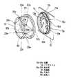
各ノブダイアル18の周壁部には、図1に示すように、前端部に位置してインジケータレンズ29a〜29fが埋設されている。これらインジケータレンズ29a〜29fは表示部に相当するものであり、LED15a〜15eはインジケータレンズ29a〜29fの後方(回動軌跡上)に位置し、ノブダイアル18が位置決めされた状態では、図2に示すように、インジケータレンズ29a〜29fのうち所定の5つがLED15a〜15eに対向する。尚、インジケータレンズ29a〜29fは、ノブダイアル18に二色成形されたものである。
【0026】
各ノブダイアル18の周壁部には、図1に示すように、6つの光通路30が形成されている。これら各光通路30は、ノブダイアル18の後面を通じて開口する入光口30aとインジケータレンズ29a〜29fに通じる出光口30bとを繋ぐものであり、各光通路30は、出光口30bから入光口30aに向って除々に幅広になる扇形状をなしている。尚、符号30cは、光通路30相互間に位置する遮光壁部を示すものである。
【0027】
各ノブダイアル18が位置規制された状態では、各遮光壁部30cがホルダー13の仕切壁13aに対向するようになっている。従って、所定のLED15a〜15eから投射された光は、入光口30aから出光口30bを通して所定のインジケータレンズ29a〜29fに供給される。これにより、所定のインジケータレンズ29a〜29fが発光し、複数のマーク25および26を選択的に指示することに伴い、ノブダイル18による温風吹出位置および吹出量の切換状態を運転者に報知する。
【0028】
プリント配線基板12の前面には、図4に示すように、各第1の検出回路パターン24a〜24eの内周部に位置して第2の検出回路パターン31a1,31a2〜31e1,31e2が形成されており、各ノブダイアル18が位置規制された状態では、二点鎖線で示すように、コンタクト23の接点部23dが検出回路パターン31a1,31a2〜31e1,31e2間の隙間に位置するようになっている。
【0029】
従って、各ノブダイアル18を回動操作すると、ノブダイアル18の回動方向に応じた検出回路パターン31a1,31a2〜31e1,31e2にコンタクト23の接点部23dが接触し、検出回路パターン31a1,31a2〜31e1,31e2がコモン回路パターン14に選択的に導通される。すると、ECUは、後述するように、いずれの検出回路パターン31a1,31a2〜31e1,31e2から導通信号が出力されたかに基づいて、各ノブダイアル18の回動方向を判断する。
【0030】
図5に示すベゼル32は合成樹脂からなるものであり、ベゼル32の側板部には、図3に示すように、複数の係合孔32aが形成されている(1個のみ図示する)。そして、カバー11の側板には複数の爪部11aが一体形成されており(1個のみ図示する)、カバー11の外側部にベゼル32を押込むと、各係合孔32aが爪部11aに係合し、ベゼル32がカバー11に装着され、プリント配線基板12の前面がベゼル32により覆われる。
【0031】
尚、ベゼル32には、図5に示すように、円形状をなす2つの開口部32bが形成されており、各ノブダイアル18は、図3に示すように、開口部32bを通して前面側に突出している。
【0032】
プリント配線基板12の前面には、図5に示すように、ホルダー13相互間に位置してベース33が実装されており、このベース33には、最上段に位置してデフモード(コントロールエアをフロントガラスに吹付けるモード)をオンオフするためのゴム接点34aおよび34bが実装され、中段に位置してRECモード(室内で空気を循環させるモード)をオンオフするためのゴム接点34aおよび34bが実装され、最下段に位置してエアーコンディショナーをオンオフするためのゴム接点34aおよび34bが実装されている。
【0033】
ベゼル32には、矩形状をなす開口部32cが形成されており、この開口部32c内には、図2に示すように、3つの操作ノブ35が挿着されている。そして、各操作ノブ35を押圧操作すると、ゴム接点34aおよび34bからオン信号が出力される。
【0034】
各操作ノブ35にはインジケータレンズ35aが取付けられている。そして、プリント配線基板12には、図3に示すように、各操作ノブ35内に位置してLED35bが実装されており、ECUは、操作ノブ35の操作状態に応じてLED35bをオンオフすることに伴い、各インジケータレンズ35aを点灯消灯する。これにより、各操作ノブ35の操作状態(デフモード,RECモード,エアーコンディショナーの設定状態)を運転者に報知する。
【0035】
また、ベゼル32の右側部には、図2に示すように、ノブダイアル36が回動可能に装着されており、ECUは、ノブダイアル36の回動位置に応じてコントロールエアを温度調節する。
【0036】
ベゼル32には、ノブダイアル36の内方に位置して操作キー36aが設けられており、ECUは、操作キー36aの押圧操作を検出すると、オートコントロールモード(コントロールエアの吹出位置,吹出量を自動的に切換えるモード)をオンオフする。これと共に、各ノブダイアル18の回動位置に関係なく、LED15a〜15eに選択的に電源を供給することに伴い、入光口30aから出光口30bを通して所定のインジケータレンズ29a〜29fを発光させ、吹出位置、吹出量の切換状態を運転者に報知する。
【0037】
ベゼル32にはパネル37aが設けられ、これらパネルキー37aおよび37bにはインジケータレンズ38aおよび38bが設けられており、ECUは、LED(図示せず)をオンオフすることに伴い、インジケータレンズ38aおよび38bを点灯消灯させ、操作キー36aの操作状態(オートコントロールモードの設定状態)を運転者に報知する。
【0038】
次に上記構成の作用について説明する。操作キー36aの操作に伴い、吹出口オートコントロールモードおよび吹出量オートコントロールモードをオフした後、各ノブダイアル18を回動操作すると、ECUは、各ノブダイアル18の回動位置に応じたLED15a〜15eに電源を供給し、所定のインジケータレンズ29a〜29fを点灯させることに伴い、複数のマーク25および26を選択的に指示する。これにより、運転者に各ノブダイアル18の回動状態(温風吹出位置および温風吹出量の選択状態)を報知する。
【0039】
これと共に、ノブダイアル18の回動位置に応じたLED15a〜15eに電源を供給したまま、ノブダイアル18の回動方向に沿って隣接するLED15a〜15eに電源を供給する。これにより、運転者に各ノブダイアル18の回動方向を報知する。
【0040】
例えば、各ノブダイアル18の操作前には、図4に二点鎖線で示すように、各コンタクト23の接点部23cが第1の検出回路パターン24cに接触しているものとする。この状態では、各検出回路パターン24cおよび各コモン回路パターン14間が導通され、各検出回路パターン24cから導通信号が出力されている。従って、ECUは、図2のLED15cに通電することに伴い、入光口30aから出光口30bを通してインジケータレンズ29cに光を供給し、インジケータレンズ29cを発光させている。
【0041】
この状態で各ノブダイアル18が矢印A方向へ回動操作されると、図4において、各コンタクト23の接点部23dが第2の検出回路パターン31c2に接触し、第2の検出回路パターン31c2から導通信号が出力される。すると、ECUは、各ノブダイアル18の矢印A方向への回動操作が開始されたと判断し、図2において、LED15cの矢印A方向側に隣接するLED15dに電源を供給し、LED15cおよび15dを同時に点灯させる。
【0042】
LED15cおよび15dが点灯すると、LED15cからの投射光が入光口30aから出光口30bを通してインジケータレンズ29cに供給され、インジケータレンズ29cが発光状態に保持される。これと共に、LED15dからの投射光が入光口30aから出光口30bを通してインジケータレンズ29dに供給され、インジケータレンズ29dが発光する。
【0043】
この後、図4において、各コンタクト23の接点部23cが第1の検出回路パターン24dに接触し、第1の検出回路パターン24dから導通信号が出力されると、ECUは、図2のLED15cを消灯する。すると、LED15dからの投射光が入光口30aから出光口30bを通してインジケータレンズ29cに供給され、インジケータレンズ29cのみが発光する。
【0044】
上記実施例によれば、光通路30を出光口30bから入光口30aに向って幅広になる扇状に形成した。このため、ノブダイアル18が中間位置にある場合(位置規制されていない場合)でも、遮光壁部30cがLED15a〜15eに対向する一瞬を除いて、LED15a〜15eからの投射光が入光口30a内に投射され、光通路30を通してインジケータレンズ29a〜29fに供給されるようになるので、インジケータレンズ29a〜29fを極力照明することができる。
【0045】
また、ノブダイアル18の回動操作が開始されると、ノブダイアル18の回動位置に応じたLED15a〜15eに電源を供給したまま、ノブダイアル18の回動方向に沿って隣接するLED15a〜15eに電源を供給した。このため、ノブダイアル18の回動方向が報知されるので、使い勝手が向上する。
【0046】
また、筒部17aの3面に板ばね22を係合させることに伴い、ノブダイアル18の回動を規制した。このため、ノブダイアル18の操作に伴い板ばね22が回動すると、板ばね22が筒部17aの3つの隅部により押圧され、押圧方向と同方向へ撓むようになる。このため、ノブダイアル18の回動抵抗が低減されるので、ノブダイアル18の操作フィーリングが軽快になり、特に中間位置での操作フィーリングが重くなることが防止される。
【0047】
次に本発明の第2実施例を図6に基づいて説明する。尚、上記第1実施例と同一の部材については同一の符号を付して説明を省略し、以下、異なる部材についてのみ説明を行う。左側に位置するノブボディ19内には、ばね部材に相当する2本の線ばね39が収容され、右側に位置するノブボディ19内には、ばね部材に相当する1本の線ばね39が収容されている。
【0048】
これら各線ばね39は三角形状に折曲されたものであり、各線ばね39には3つの係合部39aが形成されている。そして、これら各係合部39aは、ノブボディ19の溝部19b内に差込まれており、左側に位置するノブダイアル18は、筒部17aの3面に2本の線ばね39が係合することに伴い回動規制され、右側に位置するノブダイアル18は、筒部17aの3面に1本の線ばね39が係合することに伴い回動規制されている。
【0049】
上記実施例によれば、左側に位置するノブダイアル18の回動操作に伴い、2本の線ばね39が回動すると、各線ばね39が筒部17aの3つの隅部により押圧されて同方向へ撓む。この後、筒部17aの3つの隅部が各線ばね39を乗越え、新たな3面が2本の線ばね39に係合すると、ノブダイアル18の回動が規制される。このため、ノブダイアル18の回動抵抗が低減されるので、ノブダイアル18の操作フィーリングが軽快になり、中間停止が防止される。しかも、ばね部材として板ばね22を用いていた第1実施例とは異なり、線ばね39を用いているので、ノブダイアル18等の高さ寸法を小さくできる。
【0050】
また、右側に位置するノブダイアル18の回動操作に伴い、1本の線ばね39が回動すると、線ばね39が筒部17aの3つの隅部により押圧されて同方向へ撓む。この後、筒部17aの3つの隅部が線ばね39を乗越え、新たな3面が線ばね39に係合すると、ノブダイアル18の回動が規制される。このため、ノブダイアル18の回動抵抗が低減されるので、ノブダイアル18の操作フィーリングが軽快になり、中間停止が防止される。しかも、ばね部材として線ばね39を用いているので、ノブダイアル18等の高さ寸法を小さくできる。
【0051】
また、左側のノブダイアル18に対して2本の線ばね39を使用し、右側のノブダイアル18に対して1本の線ばね39を使用することに伴い、両ノブダイアル18の操作力を相違させた。このため、操作感覚で2つのノブダイアル18を簡単に区別できるので、ノブダイアル18の操作性が向上する。
【0052】
ところで、上記第1実施例においては、両ノブダイアル18の操作力を相違させようとすると、両板ばね22の高さ寸法を相違させる等してばね力を調整する必要がある。このため、両板ばね22を注意深く識別してノブダイアル18に装着する手間が必要になる。
【0053】
この点、本実施例では、両ノブダイアル18に対して異本数の線ばね39を用いている。このため、両板ばね22を注意深く識別してノブダイアル18に装着する手間が不要になるので、組立作業性が向上する。これと共に、品種が異なる板ばね22を製造する場合とは異なり、1種類の線ばね39で対応できるので、部品種を削減できる利点もある。
【0054】
尚、上記第2実施例においては、左側に位置するノブボディ19内に2本の線ばね39を収容し、右側に位置するノブボディ19内に1本の線ばね39を収容したが、これに限定されるものではなく、線ばね39の本数は必要に応じて調整すれば良い。
また、上記第2実施例においては、両ノブボディ19内に線ばね39を収容したが、これに限定されるものではなく、例えば、板ばね22および線ばね39の双方を収容することに伴い、両ノブダイアル18の操作力を調整しても良い。
【0055】
また、上記第1および第2実施例においては、各ノブダイアル18の回動方向を検出する第2の検出回路パターン31a1,31a2〜31e1,31e2をプリント配線基板12に形成したが、これに限定されるものではなく、例えば、第2の検出回路パターン31a1,31a2〜31e1,31e2を廃止しても良い。この構成の場合、各コンタクト23の接点部23dも廃止すると良い。
【0056】
また、上記第1および第2実施例においては、筒部17aをホルダー13に固定し、ノブダイアル18と一体的に板ばね22および線ばね39を回動させる構成としたが、これに限定されるものではなく、例えば、板ばね22あるいは線ばね39をホルダー13に固定し、ノブダイアル18と一体的に筒部17aを回動させる構成としても良い。
【0057】
また、上記第1および第2実施例においては、断面六角形状の筒部17aと、三角形状の板ばね22および線ばね39を用い、筒部17aの3面に板ばね22および線ばね39を係合させたが、これに限定されるものではなく、例えば、一直状の板ばねおよび線ばねを用い、筒部17aの1面に板ばねおよび線ばねを係合させても良い。
【0058】
また、上記第1および第2実施例においては、ノブダイアル18を60°ピッチで位置規制する構成としたが、これに限定されるものではなく、例えば30°ピッチで位置規制する構成としても良い。この構成の場合、筒部17aを断面12角形状に形成し、板ばね22および線ばね39を六角形状に形成すると良い。また、上記第1および第2実施例においては、本発明を自動車のヒータコントローラに適用したが、これに限定されるものではなく、要は、複数の表示部を選択的に照明することに伴い、ノブダイアルの回動位置を報知する構成のダイアル操作装置全般に広く適用できる。
【0059】
【発明の効果】
以上の説明から明らかなように、本発明のダイアル操作装置は次の効果を奏する。
請求項1記載の手段によれば、光通路を出光口から入光口に向って幅広になる扇状に形成した。このため、ノブダイアルが中間位置にある場合でも、光源からの投射光が光通路を通して表示部に供給されるようになるので、表示部を極力照明することができる。
請求項2記載の手段によれば、ノブダイアルの回動位置に応じた光源を点灯させたまま、次の回動位置に応じた光源を点灯させた。このため、ノブダイアルの次の回動位置に応じた表示部が照明されるようになるので、ノブダイアルの回動方向を報知できる。
【図面の簡単な説明】
【図1】本発明の第1実施例を示す図(ノブダイアルを示す斜視図)
【図2】ヒータコントローラを示す前面図
【図3】ヒータコントローラを示す横断面図
【図4】プリント配線基板を示す正面図
【図5】ヒータコントローラの分解斜視図
【図6】本発明の第2実施例を示す図5相当図
【図7】従来例を示す図1相当図
【符号の説明】
15a〜15eはLED(光源)、18はノブダイアル、29a〜29fはインジケータレンズ(表示部)、30は光通路、30bは出光口、30aは入光口を示す。[0001]
TECHNICAL FIELD OF THE INVENTION
The present invention relates to a dial operating device configured to notify a rotation position of a knob dial by selectively illuminating a plurality of display units provided on the knob dial.
[0002]
[Problems to be solved by the invention]
FIG. 7 shows a conventional configuration of the dial operating device. Here, a
[0003]
A plurality of
[0004]
However, in the above-described conventional configuration, when the
[0005]
The present invention has been made in view of the above circumstances, and an object of the present invention is to provide a dial operating device capable of illuminating a display unit as much as possible even during rotation of a knob dial.
[0006]
[Means for Solving the Problems]
A dial operating device according to a first aspect of the present invention includes a knob dial that can be rotated, a plurality of translucent display units provided on the knob dial, and a plurality of display units that are arranged on the rotation locus. A plurality of light sources, a control device for selectively lighting one of the plurality of light sources according to the turning position of the knob dial, and light projected from the light source provided on the knob dial to the display unit A plurality of light paths for supplying light are provided, and each of these light paths is characterized in that it has a substantially fan-like shape whose width dimension increases from the light exit to the light entrance.
[0007]
According to the above means, the light path has a substantially fan shape, and the width dimension of the light path increases from the light exit to the light entrance. For this reason, even when the knob dial is at the intermediate position, the projection light from the light source is projected into the light entrance except for a moment when the wall portion located between the light paths faces the light source, and the display unit passes through the light path. , The display unit is illuminated as much as possible.
[0008]
The dial operating device according to
[0009]
According to the above means, when the turning operation of the knob dial is started, the light source corresponding to the turning position of the knob dial and the light source corresponding to the next turning position are turned on, and the light source corresponding to the next turning position is turned on. Projection light from a light source is supplied to a display unit through an optical path. For this reason, the display unit corresponding to the next turning position of the knob dial is illuminated, so that the turning direction of the knob dial is notified.
[0010]
BEST MODE FOR CARRYING OUT THE INVENTION
Hereinafter, a first embodiment of the present invention will be described with reference to FIGS. In this embodiment, the present invention is applied to a heater controller of an automobile, and the heater controller is mounted on an instrument panel. First, in FIG.
[0011]
As shown in FIG. 5,
[0012]
As shown in FIG. 4, two arc-shaped
[0013]
As shown in FIG. 4, on the front surface of the printed
[0014]
The
[0015]
On the outer peripheral surface of each
[0016]
As shown in FIG. 5, three
[0017]
As shown in FIG. 2, a
[0018]
As shown in FIG. 2, the three surfaces of each
[0019]
each
[0020]
On the front surface of the printed
[0021]
The vehicle is equipped with an ECU (not shown) corresponding to a control device. The ECU mainly includes a microcomputer, and detects the turning position of each
[0022]
As shown in FIG. 2, on the front surface of the
[0023]
As shown in FIG. 3, a
[0024]
A plurality of
[0025]
As shown in FIG. 1,
[0026]
As shown in FIG. 1, six
[0027]
When the position of each
[0028]
As shown in FIG. 4, on the front surface of the printed
[0029]
Therefore, when each
[0030]
The
[0031]
The
[0032]
As shown in FIG. 5, a
[0033]
In the
[0034]
An
[0035]
As shown in FIG. 2, a
[0036]
The
[0037]
The
[0038]
Next, the operation of the above configuration will be described. After turning off the air outlet automatic control mode and the blowout amount automatic control mode in accordance with the operation of the operation key 36a, when the respective knob dials 18 are rotated, the ECUs are turned on by the
[0039]
At the same time, power is supplied to the
[0040]
For example, before the operation of each
[0041]
When each
[0042]
When the
[0043]
Thereafter, in FIG. 4, when the
[0044]
According to the above embodiment, the
[0045]
Further, when the turning operation of the
[0046]
Further, the rotation of the
[0047]
Next, a second embodiment of the present invention will be described with reference to FIG. The same members as those in the first embodiment are denoted by the same reference numerals, and description thereof will be omitted. Hereinafter, only different members will be described. Two wire springs 39 corresponding to the spring members are accommodated in the
[0048]
Each of these wire springs 39 is bent in a triangular shape, and each
[0049]
According to the above embodiment, when the two wire springs 39 are rotated by the turning operation of the
[0050]
Further, when one
[0051]
In addition, since two wire springs 39 are used for the
[0052]
By the way, in the first embodiment, in order to make the operating force of both knob dials 18 different, it is necessary to adjust the spring force by making the height dimensions of both
[0053]
In this regard, in this embodiment, different numbers of wire springs 39 are used for both knob dials 18. This eliminates the need for carefully discriminating the two
[0054]
In the second embodiment, two wire springs 39 are accommodated in the
Further, in the second embodiment, the
[0055]
In the first and second embodiments, the second detection circuit patterns 31a1, 31a2 to 31e1, 31e2 for detecting the turning direction of each
[0056]
In the first and second embodiments, the
[0057]
In the first and second embodiments, the
[0058]
In the first and second embodiments, the position of the
[0059]
【The invention's effect】
As apparent from the above description, the dial operating device of the present invention has the following effects.
According to the first aspect of the present invention, the light path is formed in a fan shape which becomes wider from the light exit to the light entrance. For this reason, even when the knob dial is at the intermediate position, the projection light from the light source is supplied to the display unit through the light path, so that the display unit can be illuminated as much as possible.
According to the second aspect of the present invention, the light source corresponding to the next turning position is turned on while the light source corresponding to the turning position of the knob dial is turned on. For this reason, the display unit corresponding to the next turning position of the knob dial is illuminated, so that the turning direction of the knob dial can be notified.
[Brief description of the drawings]
FIG. 1 is a diagram showing a first embodiment of the present invention (a perspective view showing a knob dial).
FIG. 2 is a front view showing a heater controller.
FIG. 3 is a cross-sectional view showing a heater controller.
FIG. 4 is a front view showing a printed wiring board.
FIG. 5 is an exploded perspective view of a heater controller.
FIG. 6 is a view corresponding to FIG. 5, showing a second embodiment of the present invention.
FIG. 7 is a diagram corresponding to FIG. 1 showing a conventional example.
[Explanation of symbols]
15a to 15e are LEDs (light sources), 18 is a knob dial, 29a to 29f are indicator lenses (display units), 30 is a light path, 30b is a light exit, and 30a is a light entrance.
Claims (2)
Translated fromJapaneseこのノブダイアルに設けられ、透光性を有する複数の表示部と、
これら複数の表示部の回動軌跡上に配置された複数の光源と、
これら複数の光源のうち前記ノブダイアルの回動位置に応じたものを選択的に点灯させる制御装置と、
前記ノブダイアルに設けられ、前記光源から投射された光を前記表示部に供給する複数の光通路とを備え、
これら各光通路は、出光口から入光口に向って幅寸法が大きくなる略扇形状をなしていることを特徴とするダイアル操作装置。A knob dial that can be rotated,
A plurality of display units provided on the knob dial and having translucency;
A plurality of light sources arranged on the rotation locus of the plurality of display units;
A control device for selectively turning on the light source according to the turning position of the knob dial among the plurality of light sources;
A plurality of light paths that are provided on the knob dial and supply the light projected from the light source to the display unit,
A dial operating device, wherein each of these light paths has a substantially fan-like shape whose width increases from the light exit to the light entrance.
Priority Applications (5)
| Application Number | Priority Date | Filing Date | Title |
|---|---|---|---|
| JP27243196AJP3576720B2 (en) | 1996-10-15 | 1996-10-15 | Dial operating device |
| PCT/JP1997/003850WO1998016940A1 (en) | 1996-10-15 | 1997-10-15 | Dial operating apparatus |
| DE69720753TDE69720753T2 (en) | 1996-10-15 | 1997-10-15 | ACTUATING DEVICE WITH NUMBER SHEET |
| EP97944198AEP0933792B1 (en) | 1996-10-15 | 1997-10-15 | Dial operating apparatus |
| US09/284,498US6176589B1 (en) | 1996-10-15 | 1997-10-15 | Dial operating apparatus |
Applications Claiming Priority (1)
| Application Number | Priority Date | Filing Date | Title |
|---|---|---|---|
| JP27243196AJP3576720B2 (en) | 1996-10-15 | 1996-10-15 | Dial operating device |
Publications (2)
| Publication Number | Publication Date |
|---|---|
| JPH10116536A JPH10116536A (en) | 1998-05-06 |
| JP3576720B2true JP3576720B2 (en) | 2004-10-13 |
Family
ID=17513825
Family Applications (1)
| Application Number | Title | Priority Date | Filing Date |
|---|---|---|---|
| JP27243196AExpired - Fee RelatedJP3576720B2 (en) | 1996-10-15 | 1996-10-15 | Dial operating device |
Country Status (5)
| Country | Link |
|---|---|
| US (1) | US6176589B1 (en) |
| EP (1) | EP0933792B1 (en) |
| JP (1) | JP3576720B2 (en) |
| DE (1) | DE69720753T2 (en) |
| WO (1) | WO1998016940A1 (en) |
Families Citing this family (28)
| Publication number | Priority date | Publication date | Assignee | Title |
|---|---|---|---|---|
| US6522875B1 (en)* | 1998-11-17 | 2003-02-18 | Eric Morgan Dowling | Geographical web browser, methods, apparatus and systems |
| DE20010428U1 (en)* | 2000-06-09 | 2000-08-17 | Mannesmann VDO AG, 60388 Frankfurt | Arrangement for illuminating the control button of an input unit by means of transmitted light |
| US6471648B1 (en)* | 2000-07-17 | 2002-10-29 | Acuson Corporation | Medical diagnostic ultrasound imaging system with a rotatable user interface element having a non-rotatable indicator |
| US6345898B1 (en)* | 2000-12-05 | 2002-02-12 | Atico International Usa, Inc | Illuminated pad lock |
| DE10202049A1 (en)* | 2002-01-18 | 2003-07-31 | Faude Consulting Gmbh R | Switch arrangement for domestic machine or similar has contact track on circuit board contacted by sliding element via contacts; rotor switch fitting operates contact of contact element |
| DE60230738D1 (en)* | 2002-08-13 | 2009-02-26 | Vestel Elekt Sanayi Ve Ticaret | Function indicator for displaying the condition of a device |
| DE10243629A1 (en)* | 2002-09-19 | 2004-04-08 | Electrolux Home Products Corporation N.V. | Knobs, in particular retractable knobs for household appliances |
| JP3970756B2 (en)* | 2002-12-03 | 2007-09-05 | アルプス電気株式会社 | Illuminated switch device |
| US6733146B1 (en)* | 2003-01-10 | 2004-05-11 | Pat J. Vastano | Illuminated knob for indicating the operative condition of an appliance |
| DE20314364U1 (en) | 2003-09-16 | 2004-02-26 | Trw Automotive Electronics & Components Gmbh & Co. Kg | Rotary switch in a motor vehicle |
| US7633485B2 (en)* | 2004-01-29 | 2009-12-15 | Chrysler Group Llc | Single knob multifunction controller and display unit |
| US7367683B2 (en)* | 2004-03-11 | 2008-05-06 | Master Lock Company Llc | Illuminating mechanism for a lock |
| JP4367850B2 (en)* | 2004-09-27 | 2009-11-18 | シチズン電子株式会社 | Illuminated switch |
| JP4636546B2 (en)* | 2005-08-02 | 2011-02-23 | 株式会社東海理化電機製作所 | Air conditioning switch device for vehicles |
| FR2889767B1 (en)* | 2005-08-11 | 2011-05-13 | Valeo Systemes Thermiques | RETRO LIGHTING A CONTROL BUTTON WITH LIGHT GUIDE. |
| US7222979B1 (en)* | 2005-11-09 | 2007-05-29 | Cfm Corporation | Illuminated dial |
| US20070113600A1 (en)* | 2005-11-21 | 2007-05-24 | Marcelle Jesse A | Locking mechanism |
| JP4789900B2 (en)* | 2007-10-02 | 2011-10-12 | 帝国通信工業株式会社 | Composite electronic parts with illumination function |
| JP5209937B2 (en)* | 2007-10-26 | 2013-06-12 | 株式会社東海理化電機製作所 | Operating device |
| KR200450946Y1 (en) | 2008-07-15 | 2010-11-11 | 주식회사 현대오토넷 | Volume knob lighting |
| US8178802B2 (en)* | 2008-07-31 | 2012-05-15 | Electrolux Home Products, Inc. | Unitized appliance control panel assembly and components of the assembly |
| DE102009057951B4 (en)* | 2009-12-11 | 2013-07-11 | GM Global Technology Operations LLC (n. d. Ges. d. Staates Delaware) | Lighting device for an adjustment device for setting an operating parameter in a vehicle |
| KR101303172B1 (en)* | 2012-02-29 | 2013-09-09 | 알프스 덴키 가부시키가이샤 | Dimming switch assembly |
| JP5871669B2 (en)* | 2012-03-13 | 2016-03-01 | アルプス電気株式会社 | Input device with illumination function |
| JP6783530B2 (en) | 2016-03-07 | 2020-11-11 | アルプスアルパイン株式会社 | Display device and operation switch equipped with it |
| CN106783330A (en)* | 2016-12-21 | 2017-05-31 | 广东金莱特电器股份有限公司 | A kind of rotary switch shown with light |
| US10345514B2 (en)* | 2017-02-22 | 2019-07-09 | Haier Us Appliance Solutions, Inc. | Appliance and illuminated knob assembly |
| KR20200003089A (en) | 2017-04-28 | 2020-01-08 | 스트리커 코포레이션 | Systems and methods for displaying mapping of console-based surgical systems |
Family Cites Families (9)
| Publication number | Priority date | Publication date | Assignee | Title |
|---|---|---|---|---|
| JPS5324474U (en)* | 1976-08-10 | 1978-03-01 | ||
| JPS5324474A (en) | 1976-08-18 | 1978-03-07 | Santo Tekkosho Kk | Method of desizing* scouring and mercerizing textile fabric |
| CH660557A5 (en) | 1984-10-26 | 1987-05-15 | Nestle Sa | ANTI-BACTERIAL COMPOSITION AND PROCESS FOR PREPARING ITS ACTIVE INGREDIENTS. |
| JPS61103829U (en)* | 1984-12-13 | 1986-07-02 | ||
| US4761715A (en)* | 1987-03-25 | 1988-08-02 | Beede Electrical Instrument Co., Inc. | Laser pointer |
| DE3808770C2 (en) | 1988-03-16 | 1996-10-24 | Teves Gmbh Alfred | Illuminable device |
| JPH0324232A (en) | 1989-06-20 | 1991-02-01 | Nissan Motor Co Ltd | Gear induction hardening method |
| JPH0324232U (en)* | 1989-07-19 | 1991-03-13 | ||
| US5171080A (en)* | 1991-05-28 | 1992-12-15 | Allied-Signal Inc. | Method of reducing light leakage from internally illuminated panels |
- 1996
- 1996-10-15JPJP27243196Apatent/JP3576720B2/ennot_activeExpired - Fee Related
- 1997
- 1997-10-15USUS09/284,498patent/US6176589B1/ennot_activeExpired - Fee Related
- 1997-10-15DEDE69720753Tpatent/DE69720753T2/ennot_activeExpired - Fee Related
- 1997-10-15WOPCT/JP1997/003850patent/WO1998016940A1/enactiveIP Right Grant
- 1997-10-15EPEP97944198Apatent/EP0933792B1/ennot_activeExpired - Lifetime
Also Published As
| Publication number | Publication date |
|---|---|
| DE69720753T2 (en) | 2004-02-05 |
| EP0933792B1 (en) | 2003-04-09 |
| EP0933792A1 (en) | 1999-08-04 |
| DE69720753D1 (en) | 2003-05-15 |
| US6176589B1 (en) | 2001-01-23 |
| JPH10116536A (en) | 1998-05-06 |
| WO1998016940A1 (en) | 1998-04-23 |
| EP0933792A4 (en) | 2000-01-05 |
Similar Documents
| Publication | Publication Date | Title |
|---|---|---|
| JP3576720B2 (en) | Dial operating device | |
| US7381128B2 (en) | Operating device of air conditioner for vehicle | |
| EP1518728B1 (en) | Operating device of air conditioner for vehicle | |
| JP3500066B2 (en) | Dial switch | |
| US6155691A (en) | Light illuminating type manipulation and display apparatus | |
| JP3597649B2 (en) | Dial operating device | |
| JP2005096579A (en) | Operating device for vehicular air-conditioner | |
| JPH11310078A (en) | Coaxial switch with illumination | |
| US7067752B2 (en) | Seesaw button of heater control unit | |
| US6087601A (en) | Modular multi-purpose switch | |
| JP2004281205A (en) | Rotary switch | |
| JP3168502B2 (en) | Rotary switch | |
| JP2571671Y2 (en) | Lighting system for vehicle heat control panel | |
| JP2004136840A (en) | Heater control device | |
| JP2011245982A (en) | Indoor light for vehicle | |
| KR100813760B1 (en) | Structure for lighting control mode in vehicle | |
| JPH0529951Y2 (en) | ||
| KR100612159B1 (en) | Automotive control lighting equipment | |
| JP3744737B2 (en) | Dial type switch | |
| JP2000311552A (en) | Operating unit | |
| JP2002123197A (en) | Display device | |
| JPS6139997Y2 (en) | ||
| JPH0863111A (en) | Lighting device for control panel | |
| JPH0567068U (en) | Electronic device operating device | |
| JPS63102121A (en) | Illumination switch panel |
Legal Events
| Date | Code | Title | Description |
|---|---|---|---|
| A131 | Notification of reasons for refusal | Free format text:JAPANESE INTERMEDIATE CODE: A131 Effective date:20040413 | |
| TRDD | Decision of grant or rejection written | ||
| A01 | Written decision to grant a patent or to grant a registration (utility model) | Free format text:JAPANESE INTERMEDIATE CODE: A01 Effective date:20040629 | |
| A61 | First payment of annual fees (during grant procedure) | Free format text:JAPANESE INTERMEDIATE CODE: A61 Effective date:20040708 | |
| R150 | Certificate of patent or registration of utility model | Free format text:JAPANESE INTERMEDIATE CODE: R150 | |
| FPAY | Renewal fee payment (event date is renewal date of database) | Free format text:PAYMENT UNTIL: 20080716 Year of fee payment:4 | |
| FPAY | Renewal fee payment (event date is renewal date of database) | Free format text:PAYMENT UNTIL: 20090716 Year of fee payment:5 | |
| FPAY | Renewal fee payment (event date is renewal date of database) | Free format text:PAYMENT UNTIL: 20100716 Year of fee payment:6 | |
| FPAY | Renewal fee payment (event date is renewal date of database) | Free format text:PAYMENT UNTIL: 20100716 Year of fee payment:6 | |
| FPAY | Renewal fee payment (event date is renewal date of database) | Free format text:PAYMENT UNTIL: 20110716 Year of fee payment:7 | |
| FPAY | Renewal fee payment (event date is renewal date of database) | Free format text:PAYMENT UNTIL: 20120716 Year of fee payment:8 | |
| FPAY | Renewal fee payment (event date is renewal date of database) | Free format text:PAYMENT UNTIL: 20120716 Year of fee payment:8 | |
| FPAY | Renewal fee payment (event date is renewal date of database) | Free format text:PAYMENT UNTIL: 20130716 Year of fee payment:9 | |
| FPAY | Renewal fee payment (event date is renewal date of database) | Free format text:PAYMENT UNTIL: 20140716 Year of fee payment:10 | |
| LAPS | Cancellation because of no payment of annual fees |