JP3576583B2 - Data communication device - Google Patents
Data communication deviceDownload PDFInfo
- Publication number
- JP3576583B2 JP3576583B2JP32599393AJP32599393AJP3576583B2JP 3576583 B2JP3576583 B2JP 3576583B2JP 32599393 AJP32599393 AJP 32599393AJP 32599393 AJP32599393 AJP 32599393AJP 3576583 B2JP3576583 B2JP 3576583B2
- Authority
- JP
- Japan
- Prior art keywords
- communication device
- signal
- data communication
- determination
- response
- Prior art date
- Legal status (The legal status is an assumption and is not a legal conclusion. Google has not performed a legal analysis and makes no representation as to the accuracy of the status listed.)
- Expired - Fee Related
Links
Images


Landscapes
- Facsimile Transmission Control (AREA)
Description
Translated fromJapanese【0001】
【産業上の利用分野】
本発明は、外部通信装置を接続可能なデータ通信装置に関する。
【0002】
【従来の技術】
従来より、1台の電話機を接続可能なファクシミリ装置において、留守番電話ダイレクト接続モードが選択されている時に、常に留守番電話が接続され、かつ、留守録モードを行うと判断して制御を行っていた。
【0003】
【発明が解決しようとする課題】
しかしながら、上記従来例においては、常時留守番電話ダイレクト接続モードに設定して使用したいユーザにとっては、使いづらいものとなる。
【0004】
つまり、常態として、留守番電話ダイレクト接続モードに設定しておき、そばに使用者がいる場合には、着信時に、留守番電話の受話器をオフフックし、相手が人間であれば通話し、相手がファクシミリであれば、通信ボタンを押下する。また、使用者がいない場合には、本来の留守番機能の動作により、着信に対して留守番電話が自動的に応答し、相手が人間であれば留守録の処理に移行し、相手がファクシミリであれば、CNG信号あるいは無音の検出により、自動的にファクシミリ通信に移行するというような使い方をしたい場合がある。
【0005】
ところが、上述のように従来のファクシミリ装置では、留守番電話ダイレクト接続モードにおいて、着信時にそばに使用者がいて、たとえ留守番電話の受話器をオフフックし、相手が人であることを知って通話を行なおうとした場合でも、装置側では留守番電話が自動的に応答したと判断し、CNG信号あるいは無音の検出に移行し、何らかの誤検出が生じた場合には、ファクシミリ通信へ移行してしまう。
【0006】
したがって、上記のように常態として留守番電話ダイレクト接続モードに設定した形態では、円滑な使用が困難であり、システムを柔軟に活用する上で不便であった。
【0007】
本発明は、自動応答を行う外部通信装置が、手動応答で通話されている最中に、着信をデータ通信へ切換えてしまうといった誤動作を防止することを目的とする。
【0008】
【課題を解決するための手段】
本発明は、外部通信装置を接続可能なデータ通信装置において、上記外部通信装置が自動的に応答を開始するまでに受信する着呼信号の回数を、予め設定する着呼信号受信回数設定手段と、上記着呼信号に対する上記外部通信装置の応答を検出する応答検出手段と、上記外部通信装置の応答を上記応答検出手段が検出するまでに受信した着呼信号をカウントする着呼信号カウント手段と、上記着呼信号がデータ通信のための着呼であるか否かを判別する判別手段と、上記応答検出手段が上記外部通信装置の応答を検出した場合に、上記設定手段によって予め設定された回数と、上記カウント手段がカウントした値とに応じて、上記判別手段に上記判別を行わせる処理と、上記判別を行わせない処理とを選択的に制御する制御手段とを有し、上記制御手段は、上記カウント手段によるカウント値が、上記設定手段によって予め設定された回数以上である場合は上記判別を行わせる処理を選択し、上記設定手段によって予め設定された回数よりも少ない場合は上記判別を行わせない処理を選択する手段であるデータ通信装置である。
【0010】
【実施例】
図1は、本発明によるファクシミリ装置の実施例を示すブロック図である。
【0011】
図1において、接続端子8(L1、L2)は、電話回線に接続される。すなわち、信号線1a、1bは電話回線であり、これはCMLリレー2に接続される。CMLリレー2は、信号線60aに信号レベル「0」の信号が出力されている時には、CMLをオフ、すなわち、信号線1a、1bは信号線3a、3bに接続され、信号線60aに信号レベル「1」の信号が出力されている時には、CMLはオン、すなわち、信号線1a、1bは信号線2a、2bに接続される。
【0012】
CMLリレー2がオン時には、トランス(t2)6を介して信号線2a、2bは信号線5a、5bに接続され、そして、ファクシミリ通信部に接続される。また、CMLリレー2がオフの時には、オフフック検知回路11を経由して、信号線6a、6bを介して接続端子10(T1、T2)により、留守番電話あるいは普通の電話機に接続され、また、呼出信号検出回路12にも接続される。
【0013】
検出回路11は、接続端子(T1、T2)10に接続されている電話機がオフフックされているか否かを検出する回路であり、オフフックしている時には、信号線11aに信号レベル「1」の信号を出力し、オンフックしている時には、信号線11aに信号レベル「0」の信号を出力する。
【0014】
呼出信号検出回路12は、信号線3a、3bに出力されている信号を入力し、呼出信号を検出する毎に、信号線12aにパルスを発生する。
【0015】
また、信号線3a、3bはトランス(t1)4を介して信号線4a、4bに接続される。また、信号線4a、4bには、CNG信号検出回路14、DTMF検出回路16、無音検出回路18、音声認識回路40に接続される。
【0016】
CNG信号検出回路14は、信号線4a、4bに出力されている信号を入力し、1100Hzの信号を検出している時に信号線14aに信号レベル「1」の信号を出力し、1100Hzの信号を検出していない時には、信号線14aに信号レベル「0」の信号を出力する。
【0017】
DTMF検出回路16は、信号線4a、4bに出力されている信号を入力し、検出したDTMF信号をコード情報として信号線16aに出力する。
【0018】
無音検出回路18は、信号線4a、4bに出力されている信号を入力し、無音(例えば、−38dBn以下の信号)を検出している時には、信号線18aに信号レベル「1」の信号を出力し、有音(例えば、−38dBnを超える信号)を検出している時には、信号線18aに信号レベル「1」の信号を出力する。
【0019】
音声認識回路40は、信号線4a、4bに出力されている信号を入力し、認識している音声情報を信号線40aに出力する。
【0020】
ハイブリッド回路20は、送信系の信号と受信系の信号とを分離し、加算回路30からの送信信号を信号線5a、5b、2a、2b経由で電話回線(1a、1b)に送出し、相手側からの信号を電話回線(1a、1b)、信号線2a、2b経由で信号線5a、5bより受取り、信号線20a経由でV29復調器34およびV21復調器32に送るものである。
【0021】
V21変調器22は、公知のCCITT勧告V21に基づいた変調を行なう変調器であり、制御回路60からの手順信号(信号線60b)を変調し、信号線22aを通して加算回路30に送出するものである。
【0022】
読取回路24は、送信原稿から主走査方向1ライン分の画像信号を順次読み取り、白、黒の2値を表す信号列を作成し、このデータを信号線24aから符号化回路26に送るものであり、CCD(電荷結合素子)等の撮像素子と光学系とで構成されている。
【0023】
符号化回路26は、信号線24aに出力されている読取データを入力して、符号化(MH符号化あるいはMR符号化)を行い、信号線26aより出力するものである。
【0024】
V27ter またはV29変調器28は、信号線26aからの符号化データを入力し、公知のCCITT勧告V27ter (差動位相変調)またはV29(直交変調)に基づいた変調を行ない、この変調データを信号線28aを通して加算回路30に出力する。
【0025】
加算回路30は、変調器22、28の出力を加算する回路である。加算回路30の出力は、ハイブリッド回路20に送られる。
【0026】
V21復調器32は、公知のCCITT勧告V21に基づいた復調を行なうものである。この復調器32は、信号線20aによりハイブリッド回路20からの手順信号を入力し、V21復調を行い、復調データを信号線32aを通して制御回路60に送る。
【0027】
V27ter またはV29復調器34は、公知のCCITT勧告V27ter またはV29に基づいた復調を行なうものである。この復調器34は、ハイブリッド回路20からの変調画像信号を入力し、復調を行って復調データを信号線34aより復号化回路36に送出する。
【0028】
復号化回路36は、信号線34aからのデータの復号化(MH復号化あるいはMR復号化)を行う回路であり、その復号化したデータを、信号線36aを介して記録回路38に出力する。
【0029】
記録回路38は、信号線36aに出力されているデータを入力し、順次1ラインずつ記録を行うものである。
【0030】
着信モード切換ボタン42は、着信モードの切換えに使用するボタンであり、このボタンが押下される毎に、信号線42aに押下パルスを発生する。
【0031】
表示回路44は、着信モードの表示回路であり、信号線60cに信号「0」が出力されると「自動着信」と表示し、信号線60cに信号「1」が出力されると「手動着信」と表示し、信号線60cに信号「2」が出力されると「留守番電話ダイレクト接続モード」と表示し、信号線60cに信号「3」が出力されると「FAX/TEL自動切換モード」と表示する。
【0032】
そして、それ以後は、信号線42aにパルスが発生する毎に、「自動着信」→「手動着信」→「留守番電話ダイレクト接続モード」→「FAX/TEL自動切換モード」→「自動着信」の順で表示の切り換えを繰り返す。また、再度信号線60cに新たな情報がセットされた時には、その情報に基づいた表示を行う。
【0033】
そして、この表示回路44は、「自動着信」と表示している時には、信号線44aに信号「0」を出力し、「手動着信」と表示している時には、信号線44aに信号「1」を出力し、「留守番電話ダイレクト接続モード」と表示している時には、信号線44aに信号「2」を出力し、「FAX/TEL自動切換モード」と表示している時には、信号線44aに信号「3」を出力する。
【0034】
登録ボタン46は、留守番電話を起動する呼出信号の検出回路をファクシミリ装置側にも登録する時に使用するボタンである。このボタンが押下されると、信号線46aに押下パルスが発生する。
【0035】
セットキー48は、各種の設定を確定するためのキーであり、このキーが押下されると、信号線48aに押下パルスが発生する。
【0036】
テンキー50は、ダイヤル番号等の入力を行うものであり、押下されたテンキー情報は信号線50aに出力される。
【0037】
登録回路52は、留守番電話を起動する呼出信号の検出回路を登録する回路である。この登録回路52に登録する時には、信号線52aに回数情報を出力後、信号線60dにライトパルスを発生する。また、この登録回路52に登録されている情報を読み出す時には、信号線60eにリードパルスを発生する。そうすると、登録回路52に登録されている情報は信号線52aに出力される。
【0038】
記憶回路54は、留守番電話に録音されている音声を記憶する回路である。この記憶回路54に記憶する時には、信号線54aに音声情報を出力後、信号線60fにライトを発生する。一方、記憶されている情報を読み出す時には、信号線60gにリードパルスを発生する。そうすると、記憶回路54に登録されている音声情報が信号線54aに出力される。
【0039】
アラーム発生回路56は、信号線60hに信号レベル「1」の信号が出力されている時には、アラームを発生し、信号線60hに信号レベル「0」の信号が出力されている時にはアラームを発生しない。
【0040】
表示回路58は、留守番電話が接続されているか否かの確認をしてほしい旨の表示を行う回路であり、信号線60iに信号レベル「1」の信号が出力されている時には表示を行い、信号線60iに信号レベル「0」の信号が出力されている時には表示を行わない。
【0041】
制御回路60は、本実施例における1台の電話機を接続可能なファクシミリ装置において、留守番電話ダイレクト接続モード、手動着信モード、自動着信モード、およびFAX/TEL自動切換モードの着信手段と、呼出信号検出手段と、留守番電話接続時の留守番電話を起動するまでの呼出信号の検出回路登録手段とを制御し、留守番電話ダイレクト接続モード状態にて、上記登録した回数以前に、直流ループの閉結を検出した場合には、相手側から送出されるファクシミリ信号(CNG信号)の検出、あるいは無音の検出を行わずに通話モードに専念し、上記登録した回数で直流ループの閉結を検出した場合には、相手側から送出されるファクシミリ信号(CNG信号)の検出、あるいは無音の検出を行い、これらを検出した場合は、ファクシミリ通信に移行する。
【0042】
また、留守番電話ダイレクト接続モードで、呼出し信号を検出し、留守番電話が応答したと判断した場合、DTMF信号を検出すると、相手側から送出されるファクシミリ信号の検出、あるいは無音の検出をせずに、留守録モードに専念する。さらに、留守番電話ダイレクト接続モードで、留守番電話が接続されていると判断した場合、留守番電話の応答を検出した時には、応答した時点から所定時間(例えば35秒)だけ、相手側から送出されるファクシミリ信号の検出、あるいは無音の検出を行う。
【0043】
図2〜図4は、本発明の第1実施例における制御回路60の動作を示すフローチャートである。
【0044】
図2において、S72では、信号線60aに信号レベル「0」の信号を出力してCMLをオフし、S74では、信号線60cに信号「0」を出力し、着信モード表示回路44を「自動受信モード」にセットする。
【0045】
S76では、信号線60hに信号レベル「0」の信号を出力してアラーム発生回路56からアラームを発生しない状態に保持し、S78では、信号線60iに信号レベル「0」の信号を出力して留守番電話が接続されているかどうかの確認表示回路58の表示をしない状態とする。
【0046】
次に、S80では、留守録起動までの呼出信号の回数の登録が選択されたか否かを判断し、選択されると、S82に進み、登録回路52に留守録起動までの呼出信号の回数の登録を行い、選択されていないと、S84に進む。
【0047】
S84では、信号線12aの信号を入力し、呼出信号を1回検出したか否かを判断し、呼出信号を検出していないと、S86に進み、その他の処理を行う。
【0048】
また、呼出信号を1回検出すると、S88に進む。S88、S90、S92では、信号線44aの情報を入力し、着信モードを判断する。自動着信モードであると、S94に進み、手動着信モードであると、S104に進み、留守番電話ダイレクト接続モードであると、S122に進み、FAX/TEL自動切り替えモードであると、S106に進む。
【0049】
S94では、信号線60aに信号レベル「1」の信号を出力してCMLをオンし、S96では、前手順を行う。そして、S98では、画信号の受信を行い、S100では、後手順を行う。さらに、S102では、信号線60aに信号レベル「0」の信号を出力してCMLをオフし、S76に戻る。
【0050】
また、S104では、通話が行われ、その後、S76に戻る。
【0051】
また、S106では、信号線60aに信号レベル「1」の信号を出力してCMLをオンし、S108では、タイマT1に5秒をセットする。そして、S110では、図示しないトーナルカウンタ回路により、CNG信号を検出したか否かを判断し、CNG信号を検出すると、S96に進み、CNG信号を検出していないと、S112に進む。
【0052】
S112では、タイマT1がタイムオーバーしたか否かを判断し、タイマT1がタイムオーバーするとS114に進み、タイマT1がタイムオーバーしていないとS110に進む。
【0053】
S114では、不図示のオペレータ呼出し回路からオペレータ呼出しを行う。このオペレータ呼出しは、S118のYESあるいはS120のYESにより中断する。次に、S116では、タイマT1に30秒をセットし、S118では、信号線11aの信号を入力して、オフフックを検出したか否かを判断する。そして、オフフックを検出するとS104に進み、オフフックを検出していないとS120に進む。
【0054】
S120では、タイマT1がタイムオーバーしたか否かを判断し、タイマT1がタイムオーバーしていると、S76に進み、タイマT1がタイムオーバーしていないと、S118に戻る。
【0055】
また、S122では、呼出信号の回数をカウントする呼出信号カウンタに1をセットする。そして、S124では、信号線12aの信号を入力し、呼出信号を検出したか否かを判断し、呼出信号を検出していると、S126に進み、呼出信号カウンタの値を1つインクリメントする。呼出信号を検出していないと、S128に進む。
【0056】
S128では、呼出信号の周期は3秒であるので、4秒間呼出信号を検出していないか否かを判断し、4秒間呼出信号を検出していないと、S76に進み、4秒以内に呼出信号を検出していると、S130に進む。
【0057】
S130では、信号線11aの情報を入力し、電話機あるいは留守番電話により直流ループが閉結されたか否かを判断し、直流ループが閉結されると、S132に進み、直流ループが閉結されていないと、S124に進む。
【0058】
S132では、呼出信号カウンタの値が登録回路52に格納されている留守番電話を起動するための呼出信号の回数より小さいかどうかを判断し、小さい時には、留守番電話が応答したのではなく、人が受話器をオフフックしたと判断し、相手側から送出されるCNG信号の検出、あるいは無音の検出をせずにS134に進み、通話モードに専念する。
【0059】
一方、呼出信号カウンタの値が登録回路52に格納されている留守番電話を起動するための呼出信号の回数以上である時には、留守番電話が応答したと判断し、相手側から送出されるCNG信号の検出、あるいは無音の検出を行うために、S136に進む。
【0060】
S136では、タイマT1に35秒をセットする。留守番電話が応答したと判断した時点で、所定時間、例えば35秒をセットする。すなわち、呼出信号の検出時に、このタイマをセットすると、留守番電話の応答が遅い場合、留守番電話が応答する前にタイムオーバーしてしまうことがあるので、留守番電話が応答した時点でタイマをセットする。
【0061】
次に、S138では、信号線14aの信号を入力し、CNG信号を検出したか否かを判断し、CNG信号を検出すると、S94に進んで通信を行い、CNG信号を検出していないと、S140に進む。
【0062】
S140では、例えば4秒以上の無音を検出したか、すなわち、相手側は手動での送信を選択しているか否かを判断し、4秒以上の無音を検出すると、S94に進んで通信を行い、4秒以上の無音を検出していないとS142に進む。
【0063】
S142では、信号線16aの情報を入力し、DTMF信号を検出したか否かを判断し、DTMF信号を検出していると、これは留守番電話のコントコールが選択されたと判断し、相手側から送出されるCNG信号の検出、あるいは無音の検出を行わずに、S146に進んで留守録に専念する。また、DTMF信号を検出していないと、S144に進む。
【0064】
S144では、タイマT1がタイムオーバーしたか否かを判断し、タイムオーバーしていないと、S138に戻って検出を繰り返す。また、タイムオーバーすると、S146に進んで留守録に専念する。
【0065】
次に、本発明の第2実施例について説明する。
【0066】
この第2実施例では、呼出信号の回数が留守番電話接続時の留守番電話を起動するまでの呼出信号の検出回数を超えても自動応答しない場合には、留守番電話が接続されているかどうかの確認をユーザに促すためのメッセージを可視的手段としての表示回路58や可聴的手段としてのアラーム発生回路56によって出力する。
【0067】
図5は、この第2実施例の動作のうち、上記第1実施例と異なる部分を示すフローチャートである。なお、装置の構成は、図1と共通であるものとする。
【0068】
図5において、S150は上記S132のNOを表わしている。そして、S152では、呼出信号カウンタの値が登録回路52に登録されている値に等しいか否か、すなわち留守番電話が応答したか否かを判断し、留守番電話が応答していると、S154(上記S136)に進み、留守番電話が応答していないと、S156に進む。
【0069】
S156では、信号線60iに信号レベル「1」の信号を出力して留守番電話が接続されているか否かの確認表示回路58の表示を行う。なお、この表示は、オペレータの何らかのキー操作がないと消さない。このため、オペレータの操作がないうちは、上述したS78に至った場合でも、この確認表示回路58の表示を消す処理はスキップするものとする。
【0070】
また、S158では、信号線60hに信号レベル「1」の信号を所定時間、例えば30秒間出力し、アラーム発生回路56から所定時間アラームを発生する。なお、この第2実施例では、可聴的手段としてアラームを発生しているが、音声合成手段によりメッセージを出すようにしてもよい。
【0071】
この後、S160で上記S80以降に進む。
【0072】
次に、本発明の第3実施例について説明する。
【0073】
この第3実施例は、留守番電話が起動する回数を登録する手段をもたないファクシミリ装置について説明する。この場合、留守番電話ダイレクト接続モード状態にて、直流ループが閉結するまでの呼出信号の回数を常に調べて、留守番電話が起動するまでの呼出信号の検出回数を自動認識する。一例としては、常に留守番電話が起動する呼出信号の回数の最大値を記憶していき、これが所定回数(例えば、20回)を超えない範囲で、かつ、最大値が3回連続続いたときとする。ここで、20回という数は、留守番電話に設定されうる起動する呼出信号の数より大きい数とする。また、呼出信号が20回を超えても、留守番電話が自動応答しない場合には、留守番電話が接続されているか確認を促すメッセージの表示およびアラームの出力を行う。
【0074】
図6は、この第3実施例の動作のうち、上記第1実施例と異なる部分を示すフローチャートである。なお、装置の構成は、図1と共通であるものとする。
【0075】
図6において、S170は上記S78を表わしている。そして、S172では、登録回路52に留守録起動までの呼出信号の回数のデフォルト値として、0をセットしておく。すなわち、留守番電話ダイレクト接続モードになっている時には、常に留守番電話が応答したと判断する。そして、S174で上記S84に移行する。
【0076】
また、S176は、上記S130のYESを表わしている。そして、S178では、呼出信号カウンタの過去3回の値を記憶しておく。
【0077】
次に、S180では、今回の呼出信号のカウンタが20回を超えたか否かを判断し、20回を超えていると、S182(上記S156)に進み、20回以下であるとS184に進む。
【0078】
S184では、過去3回の呼出信号の回数が一致したか否かを判断する。そして、過去3回の呼出信号の回数が一致していると、S186に進み、一致していないと、S188(上記S132)に進む。
【0079】
S186では、登録回路52に過去3回一致した値を留守録起動までの呼出信号の回数と判断して記憶しておき、S188(上記S132)に進む。
【0080】
次に、本発明の第4実施例について説明する。
【0081】
この第4実施例は、上記第3実施例に対して、さらに音声認識手段を設け、留守番電話が応答した時には、常に同一の音声メッセージとなることを利用し、より正確に留守番電話が起動するまでの呼出信号の検出回数を正しく自動認識するようにしたものである。
【0082】
図7は、この第4実施例の動作のうち、上記第1実施例と異なる部分を示すフローチャートである。なお、装置の構成は、図1と共通であるものとする。
【0083】
図7において、S190は上記S178を表わしている。そして、S192では、過去3回の音声を信号線40aの情報を入力し、音声記憶回路54に記憶しておく。この後、S194で上記S180に進む。
【0084】
また、S196は、S184のYESを表わしている。そして、S198では、音声記憶回路54に記憶されている音声メッセージを入力して、過去3回の音声メッセージは同一であるか否かを判断し、同一であるとS200(上記S186)に進み、同一でないとS202(上記S188)に進む。
【0085】
【発明の効果】
本発明によれば、外部通信装置が応答した後の処理を、その応答に応じて適切に選択して行うことができ、たとえば、外部通信装置が自動応答した場合には、データ通信のための着呼であるか否かを判別するので、着信を速やかにデータ通信へ切換えることができ、一方、外部通信装置がオペレータの操作によって手動応答した場合には、データ通信のための着呼であるか否かを判別しないので、オペレータの通話中に着信をデータ通信へ切換えるという誤動作を防止することができるという効果を奏する。
【図面の簡単な説明】
【図1】本発明の実施例を示すブロック図である。
【図2】本発明の第1実施例の動作を示すフローチャートである。
【図3】上記第1実施例の動作を示すフローチャートである。
【図4】上記第1実施例の動作を示すフローチャートである。
【図5】本発明の第2実施例の動作を示すフローチャートである。
【図6】本発明の第3実施例の動作を示すフローチャートである。
【図7】本発明の第4実施例の動作を示すフローチャートである。
【符号の説明】
2…CMLリレー、
11…オフフック検出回路、
12…呼出信号検出回路、
14…CNG信号検出回路、
16…DTMF検出回路、
18…無音検出回路、
20…ハイブリッド回路、
22、28…変調器、
24…読取回路、
26…符号化回路、
30…加算回路、
32、34…復調器、
36…復号化回路、
38…記録回路、
40…音声認識回路、
42…着信モード切換ボタン、
44…着信モード表示回路、
46…登録ボタン、
48…セットキー、
50…テンキー、
52…登録回路、
54…記憶回路、
56…アラーム発生回路、
58…確認表示回路、
60…制御回路。[0001]
[Industrial applications]
The present invention relates to adata communication device to which anexternal communication device can be connected.
[0002]
[Prior art]
2. Description of the Related Art Conventionally, in a facsimile apparatus to which one telephone can be connected, when the answering machine direct connection mode is selected, it is determined that the answering machine is always connected and the answering machine mode is performed, and control is performed. .
[0003]
[Problems to be solved by the invention]
However, in the above-mentioned conventional example, it is difficult for a user who wants to always set and use the answering machine direct connection mode to use.
[0004]
In other words, as usual, set the answering machine direct connection mode, if there is a user nearby, off-hook the answering machine handset at the time of an incoming call, if the other party is a human, talk on the phone, and if the other party is a facsimile If there is, press the communication button. If there is no user, the answering machine automatically responds to the incoming call due to the operation of the answering machine function. If the other party is a human, it shifts to answering machine processing, and if the other party is a facsimile, For example, there may be a case where the user wants to use facsimile communication automatically upon detection of a CNG signal or silence.
[0005]
However, as described above, in the conventional facsimile apparatus, in the answering machine direct connection mode, a user is present at the time of receiving an incoming call, and even if the answering machine is off-hook, the user knows that the other party is a person and makes a call. Even if an attempt is made, the apparatus determines that the answering machine has automatically answered, shifts to the detection of a CNG signal or silence, and shifts to facsimile communication if any erroneous detection occurs.
[0006]
Therefore, in the mode in which the answering machine direct connection mode is set as a normal state as described above, smooth use is difficult, and it is inconvenient to use the system flexibly.
[0007]
SUMMARY OF THE INVENTION It is anobject of the present invention to prevent a malfunction inwhich an external communication device that performs an automatic response switches an incoming call to a data communication during a telephone call in a manual response .
[0008]
[Means for Solving the Problems]
The present invention is a data communication device to which an external communication device can be connected, wherein the number of incoming call signals received before the external communication device automatically starts a response is set to a number of incoming call signal reception times setting means. Response detecting means for detecting a response of the external communication device to the incoming signal, and incoming signal counting means for counting incoming signals received until the response detecting means detects the response of the external communication device; Determining means for determining whether or not the incoming signal is an incoming call for data communication, and when the response detecting means detects a response from the external communication device, the setting means sets in advance. Control means for selectively controlling processing for causing the determination means to perform the determination and processing for not performing the determination in accordance with the number of times and the value counted by the counting means; The control means selects a process for making the determination when the count value of the counting means is equal to or more than the number of times preset by the setting means, and when the count value is less than the number of times preset by the setting means, This is a data communication device that is means for selecting a process that does not perform the determination.
[0010]
【Example】
FIG. 1 is a block diagram showing an embodiment of a facsimile apparatus according to the present invention.
[0011]
In FIG. 1, connection terminals 8 (L1, L2) are connected to a telephone line. That is, the signal lines 1a and 1b are telephone lines, which are connected to the
[0012]
When the
[0013]
The detection circuit 11 is a circuit for detecting whether or not the telephone connected to the connection terminals (T1, T2) 10 is off-hook. When the telephone is off-hook, a signal of signal level "1" is sent to the signal line 11a. And outputs a signal of a signal level "0" to the signal line 11a when on-hook.
[0014]
The paging
[0015]
The signal lines 3a and 3b are connected to the signal lines 4a and 4b via the transformer (t1) 4. The signal lines 4a and 4b are connected to a CNG signal detection circuit 14, a DTMF detection circuit 16, a silence detection circuit 18, and a speech recognition circuit 40.
[0016]
The CNG signal detection circuit 14 inputs the signals output to the signal lines 4a and 4b, outputs a signal of signal level "1" to the signal line 14a when detecting a signal of 1100 Hz, and outputs a signal of 1100 Hz. When no signal is detected, a signal of signal level "0" is output to the signal line 14a.
[0017]
The DTMF detection circuit 16 inputs the signals output to the signal lines 4a and 4b, and outputs the detected DTMF signal to the signal line 16a as code information.
[0018]
The silence detection circuit 18 inputs the signal output to the signal lines 4a and 4b, and when detecting silence (for example, a signal of -38 dBn or less), outputs the signal of the signal level "1" to the signal line 18a. When a sound (for example, a signal exceeding -38 dBn) is detected, a signal having a signal level "1" is output to the signal line 18a.
[0019]
The voice recognition circuit 40 receives the signals output on the signal lines 4a and 4b, and outputs the recognized voice information to the
[0020]
The hybrid circuit 20 separates the transmission system signal and the reception system signal, sends the transmission signal from the
[0021]
The V21 modulator 22 is a modulator that performs modulation based on the known CCITT recommendation V21, modulates a procedural signal (signal line 60b) from the
[0022]
The reading circuit 24 sequentially reads image signals for one line in the main scanning direction from a transmission document, creates a signal sequence representing binary values of white and black, and sends this data to the encoding circuit 26 from the
[0023]
The coding circuit 26 receives the read data output to the
[0024]
The V27ter or
[0025]
The
[0026]
The
[0027]
The V27ter or
[0028]
The
[0029]
The recording circuit 38 inputs the data output to the
[0030]
The incoming call mode switching button 42 is a button used to switch the incoming call mode. Each time this button is pressed, a pressing pulse is generated on the signal line 42a.
[0031]
The
[0032]
Thereafter, every time a pulse is generated on the signal line 42a, the order of “automatic incoming call” → “manual incoming call” → “answering machine direct connection mode” → “FAX / TEL automatic switching mode” → “automatic incoming call” The display is switched repeatedly with. When new information is set on the signal line 60c again, display based on the information is performed.
[0033]
The
[0034]
The
[0035]
The
[0036]
The
[0037]
The
[0038]
The storage circuit 54 is a circuit for storing the voice recorded on the answering machine. When storing the data in the storage circuit 54, the audio information is output to the signal line 54a, and then the write is generated to the signal line 60f. On the other hand, when reading stored information, a read pulse is generated on the
[0039]
The
[0040]
The
[0041]
In the facsimile apparatus to which one telephone can be connected according to the present embodiment, the
[0042]
Also, in the answering machine direct connection mode, when a ringing signal is detected and it is determined that the answering machine has answered, if a DTMF signal is detected, the facsimile signal sent from the other party or the detection of silence is not performed. , Concentrate on answering machine mode. Furthermore, in the answering machine direct connection mode, if it is determined that the answering machine is connected, and if a response of the answering machine is detected, a facsimile sent from the other party for a predetermined time (for example, 35 seconds) from the time of the answering. Signal detection or silence detection is performed.
[0043]
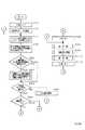
2 to 4 are flowcharts showing the operation of the
[0044]
In FIG. 2, in S72, a signal of a signal level "0" is output to the signal line 60a to turn off the CML. In S74, a signal "0" is output to the signal line 60c and the incoming
[0045]
In S76, a signal of signal level "0" is output to the signal line 60h and the
[0046]
Next, in S80, it is determined whether or not the registration of the number of call signals until the start of the answering machine is selected. Registration is performed, and if not selected, the process proceeds to S84.
[0047]
In S84, the signal of the
[0048]
When the call signal is detected once, the process proceeds to S88. In S88, S90, and S92, information on the signal line 44a is input, and the incoming call mode is determined. If the mode is the automatic incoming call mode, the process proceeds to S94. If the mode is the manual incoming call mode, the process proceeds to S104. If the mode is the answering machine direct connection mode, the process proceeds to S122. If the mode is the automatic fax / TEL switching mode, the process proceeds to S106.
[0049]
In S94, a signal of the signal level "1" is output to the signal line 60a to turn on the CML, and in S96, the pre-procedure is performed. Then, in S98, the image signal is received, and in S100, the post-procedure is performed. Further, in S102, a signal of the signal level "0" is output to the signal line 60a to turn off the CML, and the process returns to S76.
[0050]
In S104, a call is made, and thereafter, the process returns to S76.
[0051]
In S106, a signal of signal level "1" is output to the signal line 60a to turn on the CML, and in S108, the timer T1 is set to 5 seconds. Then, in S110, it is determined whether or not a CNG signal is detected by a tonal counter circuit (not shown). If a CNG signal is detected, the process proceeds to S96. If a CNG signal is not detected, the process proceeds to S112.
[0052]
In S112, it is determined whether or not the timer T1 has timed out. If the timer T1 has timed out, the process proceeds to S114, and if the timer T1 has not timed out, the process proceeds to S110.
[0053]
In S114, an operator is called from an operator calling circuit (not shown). This operator call is interrupted by YES in S118 or YES in S120. Next, in S116, 30 seconds are set in the timer T1, and in S118, the signal on the signal line 11a is input to determine whether or not an off-hook is detected. When an off-hook is detected, the process proceeds to S104, and when an off-hook is not detected, the process proceeds to S120.
[0054]
In S120, it is determined whether or not the timer T1 has timed out. If the timer T1 has timed out, the process proceeds to S76, and if the timer T1 has not timed out, the process returns to S118.
[0055]
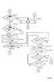
In S122, 1 is set to a call signal counter for counting the number of call signals. Then, in S124, the signal of the
[0056]
In S128, since the cycle of the call signal is 3 seconds, it is determined whether or not the call signal is detected for 4 seconds. If the call signal is not detected for 4 seconds, the process proceeds to S76 and the call is made within 4 seconds. If a signal has been detected, the process proceeds to S130.
[0057]
In S130, the information of the signal line 11a is input, and it is determined whether or not the DC loop is closed by the telephone or the answering machine. When the DC loop is closed, the process proceeds to S132, and the DC loop is closed. If not, the process proceeds to S124.
[0058]
In S132, it is determined whether or not the value of the call signal counter is smaller than the number of call signals for activating the answering machine stored in the
[0059]
On the other hand, when the value of the call signal counter is equal to or greater than the number of call signals for activating the answering machine stored in the
[0060]
In S136, 35 seconds are set in the timer T1. When it is determined that the answering machine has answered, a predetermined time, for example, 35 seconds is set. In other words, if this timer is set when a call signal is detected, if the answering machine responds slowly, the time may be over before the answering machine answers, so the timer is set when the answering machine answers.
[0061]
Next, in S138, the signal of the signal line 14a is input, and it is determined whether or not the CNG signal is detected. When the CNG signal is detected, the process proceeds to S94 and communication is performed. Proceed to S140.
[0062]
In S140, for example, it is determined whether or not silence of 4 seconds or more has been detected, that is, whether the other party has selected manual transmission or not. If silence of 4 seconds or more has been detected, the flow proceeds to S94 to perform communication. If no silence for 4 seconds or longer is detected, the process proceeds to S142.
[0063]
In S142, the information on the signal line 16a is input, and it is determined whether or not the DTMF signal has been detected. If the DTMF signal has been detected, it is determined that the answering machine call has been selected. Without detecting the transmitted CNG signal or detecting silence, the process proceeds to S146 to concentrate on the answering machine. If the DTMF signal has not been detected, the process proceeds to S144.
[0064]
In S144, it is determined whether or not the timer T1 has timed out. If not, the process returns to S138 and repeats the detection. When the time is over, the process goes to S146 to concentrate on the answering machine.
[0065]
Next, a second embodiment of the present invention will be described.
[0066]
In the second embodiment, if the automatic answering is not performed even if the number of call signals exceeds the number of times the call signal is detected until the answering machine is activated when the answering machine is connected, it is checked whether the answering machine is connected. Is output by the
[0067]
FIG. 5 is a flowchart showing a part of the operation of the second embodiment that is different from that of the first embodiment. The configuration of the device is assumed to be the same as that of FIG.
[0068]
In FIG. 5, S150 represents NO in S132. In S152, it is determined whether or not the value of the call signal counter is equal to the value registered in the
[0069]
In S156, a signal of the signal level "1" is output to the signal line 60i, and the
[0070]
In S158, a signal of the signal level "1" is output to the signal line 60h for a predetermined time, for example, 30 seconds, and the
[0071]
Thereafter, the process proceeds to S160 and subsequent steps in S160.
[0072]
Next, a third embodiment of the present invention will be described.
[0073]
In the third embodiment, a facsimile apparatus having no means for registering the number of times the answering machine is activated will be described. In this case, in the answering machine direct connection mode state, the number of calling signals until the DC loop is closed is always checked, and the number of detections of the calling signal until the answering machine is activated is automatically recognized. As an example, the maximum value of the number of ringing signals that activates the answering machine is always stored, and the maximum value is not more than a predetermined number (for example, 20 times) and the maximum value continues for three consecutive times. I do. Here, the number of 20 times is larger than the number of ringing signals to be activated that can be set to the answering machine. If the answering machine does not automatically answer even if the calling signal exceeds 20 times, a message prompting confirmation of whether the answering machine is connected or not and an alarm are output.
[0074]
FIG. 6 is a flowchart showing a part of the operation of the third embodiment that is different from that of the first embodiment. The configuration of the device is assumed to be the same as that of FIG.
[0075]
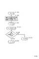
In FIG. 6, step S170 represents step S78. Then, in S172, 0 is set in the
[0076]
S176 represents YES in S130. Then, in S178, the last three values of the call signal counter are stored.
[0077]
Next, in S180, it is determined whether or not the current call signal counter has exceeded 20 times, and if it has exceeded 20, the flow proceeds to S182 (S156 above), and if not, the flow proceeds to S184.
[0078]
In S184, it is determined whether or not the numbers of the past three call signals match. If the numbers of the past three call signals match, the process proceeds to S186; otherwise, the process proceeds to S188 (S132).
[0079]
In S186, the value matched three times in the past is determined and stored in the
[0080]
Next, a fourth embodiment of the present invention will be described.
[0081]
In the fourth embodiment, a voice recognizing means is further provided in the third embodiment, and when the answering machine answers, utilizing the fact that the same voice message is always used, the answering machine is activated more accurately. The number of times of detection of the call signal up to is automatically recognized correctly.
[0082]
FIG. 7 is a flowchart showing a part of the operation of the fourth embodiment that is different from that of the first embodiment. The configuration of the device is assumed to be the same as that of FIG.
[0083]
In FIG. 7, S190 represents the above S178. Then, in S192, the information of the
[0084]
S196 represents YES in S184. Then, in S198, the voice message stored in the voice storage circuit 54 is input, and it is determined whether the voice messages of the past three times are the same, and if they are the same, the process proceeds to S200 (S186), If they are not the same, the process proceeds to S202 (S188).
[0085]
【The invention's effect】
According to the present invention, the process after the external communication device responds can be appropriately selected and performed according to the response. For example, when the external communication device automatically responds, the process for data communication is performed. Since it is determined whether or not the call is an incoming call, the incoming call can be promptly switched to the data communication. On the other hand, when the external communication device manually responds by the operation of the operator, the incoming call is for the data communication. Since it is not determined whether the call is received or not, an erroneous operation of switching the incoming call to the data communication during the call of the operator can be prevented.
[Brief description of the drawings]
FIG. 1 is a block diagram showing an embodiment of the present invention.
FIG. 2 is a flowchart showing the operation of the first embodiment of the present invention.
FIG. 3 is a flowchart showing the operation of the first embodiment.
FIG. 4 is a flowchart showing the operation of the first embodiment.
FIG. 5 is a flowchart showing the operation of the second embodiment of the present invention.
FIG. 6 is a flowchart showing the operation of the third embodiment of the present invention.
FIG. 7 is a flowchart showing the operation of the fourth embodiment of the present invention.
[Explanation of symbols]
2 ... CML relay,
11 Off-hook detection circuit
12 ... Paging signal detection circuit
14 ... CNG signal detection circuit,
16 DTMF detection circuit,
18. Silence detection circuit
20 ... Hybrid circuit,
22, 28 ... modulator,
24 reading circuit,
26 ... encoding circuit,
30 ... addition circuit,
32, 34 ... demodulator,
36 ... Decoding circuit,
38 recording circuit,
40 ... voice recognition circuit,
42 ... incoming mode switch button
44 ... incoming mode display circuit
46… Registration button,
48… Set key,
50 ... numeric keypad,
52 ... registration circuit,
54 ... memory circuit,
56 ... Alarm generation circuit,
58: confirmation display circuit,
60 ... Control circuit.
Claims (14)
Translated fromJapanese上記外部通信装置が自動的に応答を開始するまでに受信する着呼信号の回数を、予め設定する着呼信号受信回数設定手段と;
上記着呼信号に対する上記外部通信装置の応答を検出する応答検出手段と;
上記外部通信装置の応答を上記応答検出手段が検出するまでに受信した着呼信号をカウントする着呼信号カウント手段と;
上記着呼信号がデータ通信のための着呼であるか否かを判別する判別手段と;
上記応答検出手段が上記外部通信装置の応答を検出した場合に、上記設定手段によって予め設定された回数と、上記カウント手段がカウントした値とに応じて、上記判別手段に上記判別を行わせる処理と、上記判別を行わせない処理とを選択的に制御する制御手段と;
を有し、上記制御手段は、上記カウント手段によるカウント値が、上記設定手段によって予め設定された回数以上である場合は上記判別を行わせる処理を選択し、上記設定手段によって予め設定された回数よりも少ない場合は上記判別を行わせない処理を選択する手段であることを特徴とするデータ通信装置In a data communication device to which an external communication device can be connected,
Means for setting the number of incoming call signals to be received before the external communication device automatically starts a response;
Response detecting means for detecting a response of the external communication device to the incoming call signal;
Incoming signal counting means for counting incoming signals received until the response detecting means detects a response from the external communication device;
Determining means for determining whether the incoming signal is an incoming call for data communication;
When the response detecting means detects a response from the external communication device, a process of causing the determining means to perform the determination according to the number of times preset by the setting means and the value counted by the counting means. And control means for selectively controlling the processing for not performing the determination.
When the count value of the counting means is equal to or greater than the number of times preset by the setting means, the control means selects a process for performing the determination, and the number of times preset by the setting means A data communication device for selecting a process that does not perform the determination when the number is less than
上記外部通信装置が着呼に対して自動的に応答する自動応答モードを設定するモード設定手段を有し、
上記制御手段は、上記モード設定手段による設定に応じて、上記制御を行うことを特徴とするデータ通信装置。In claim 1,
The external communication device has mode setting means for setting an automatic response mode for automatically responding to an incoming call,
The data communication device, wherein the control means performs the control according to the setting by the mode setting means.
上記判別手段は、データ通信を示す信号の検出に基づいて、上記判別を行う手段であることを特徴とするデータ通信装置。In claim 1,
The data communication device according to claim 1, wherein the determination unit is a unit that performs the determination based on detection of a signal indicating data communication.
上記判別手段は、所定時間以上の無音の検出に基づいて、上記判別を行う手段であることを特徴とするデータ通信装置。In claim 1,
The data communication device according to claim 1, wherein the determination means is a means for performing the determination based on detection of silence for a predetermined time or more.
上記設定手段により予め設定された回数は、オペレータによって登録された値であることを特徴とするデータ通信装置。In claim 1,
The data communication device, wherein the number of times set in advance by the setting means is a value registered by an operator.
上記設定手段により予め設定された回数は、自動的に登録される値であることを特徴とするデータ通信装置。In claim 1,
The data communication device, wherein the number of times preset by the setting means is a value automatically registered.
上記応答検出手段は、回線の直流ループに基づいて、上記外部通信装置の応答を検出する手段であることを特徴とするデータ通信装置。In claim 1,
The data communication device according to claim 1, wherein said response detecting means is a means for detecting a response of said external communication device based on a DC loop of a line.
上記応答検出手段は、上記外部通信装置からの信号に基づいて、上記外部通信装置の応答を検出する手段であることを特徴とするデータ通信装置。In claim 1,
The data communication device, wherein the response detection means is a means for detecting a response of the external communication device based on a signal from the external communication device.
上記外部通信装置からの信号は、音声メッセージであることを特徴とするデータ通信装置。In claim 8,
The data communication device, wherein the signal from the external communication device is a voice message.
上記制御手段は、上記判別を行っている最中に、上記外部通信装置を操作する信号が検出された場合は、上記判別を中止することを特徴とするデータ通信装置。In claim 1,
The data communication device, wherein the control means stops the determination when a signal for operating the external communication device is detected during the determination.
上記判別手段は、上記判別が所定時間行われる手段であることを特徴とするデータ通信装置。In claim 1,
The data communication device according to claim 1, wherein the determination unit is a unit that performs the determination for a predetermined time.
上記カウント手段によるカウント値が所定値以上になっても上記外部通信装置の応答が検出されない場合は、所定の警告を行うことを特徴とするデータ通信装置。In claim 1,
A data communication device wherein a predetermined warning is issued when a response from the external communication device is not detected even when the count value of the counting means becomes equal to or more than a predetermined value.
上記所定の警告は、上記外部通信装置が接続されているか否かの確認を使用者に促すための可視的あるいは可聴的手段によって行われることを特徴とするデータ通信装置。In claim 12,
The data communication device according to claim 1, wherein the predetermined warning is issued by a visual or audible means for prompting a user to confirm whether or not the external communication device is connected.
上記データ通信装置は、ファクシミリ装置であり、
上記判別手段は、ファクシミリ通信を示す信号、あるいは、所定時間以上の無音の検出に応じて、上記判別を行う手段であることを特徴とするデータ通信装置。In claim 1,
The data communication device is a facsimile device,
The data communication device according to claim 1, wherein the determination means is a means for performing the determination in accordance with a signal indicating facsimile communication or detection of silence for a predetermined time or more.
Priority Applications (1)
| Application Number | Priority Date | Filing Date | Title |
|---|---|---|---|
| JP32599393AJP3576583B2 (en) | 1993-11-30 | 1993-11-30 | Data communication device |
Applications Claiming Priority (1)
| Application Number | Priority Date | Filing Date | Title |
|---|---|---|---|
| JP32599393AJP3576583B2 (en) | 1993-11-30 | 1993-11-30 | Data communication device |
Publications (2)
| Publication Number | Publication Date |
|---|---|
| JPH07154562A JPH07154562A (en) | 1995-06-16 |
| JP3576583B2true JP3576583B2 (en) | 2004-10-13 |
Family
ID=18182907
Family Applications (1)
| Application Number | Title | Priority Date | Filing Date |
|---|---|---|---|
| JP32599393AExpired - Fee RelatedJP3576583B2 (en) | 1993-11-30 | 1993-11-30 | Data communication device |
Country Status (1)
| Country | Link |
|---|---|
| JP (1) | JP3576583B2 (en) |
- 1993
- 1993-11-30JPJP32599393Apatent/JP3576583B2/ennot_activeExpired - Fee Related
Also Published As
| Publication number | Publication date |
|---|---|
| JPH07154562A (en) | 1995-06-16 |
Similar Documents
| Publication | Publication Date | Title |
|---|---|---|
| JPH02244867A (en) | Facsimile equipment with automatic answering telephone and facsimile switching function | |
| US5022072A (en) | Communication apparatus | |
| JP3450436B2 (en) | Facsimile machine | |
| US6463132B1 (en) | Communication system having the capability of selecting an optimum communication mode from a plurality of modes, depending on the type of equipment at a party to be communicated with | |
| JP3576583B2 (en) | Data communication device | |
| JP2680885B2 (en) | Data communication device | |
| US5513253A (en) | Facsimile apparatus | |
| JP3604718B2 (en) | Facsimile apparatus and control method thereof | |
| JPH06284224A (en) | Communication equipment and communication control method | |
| JP2537171B2 (en) | Image communication device | |
| JP3267804B2 (en) | Facsimile communication device | |
| US5428672A (en) | Communication apparatus | |
| JP2954957B2 (en) | Facsimile machine with redial function | |
| JPH0416055A (en) | Picture communication equipment | |
| JP3604730B2 (en) | Facsimile machine | |
| JP3302207B2 (en) | Facsimile machine | |
| JP2514109B2 (en) | Fax machine with telephone | |
| JP2637444B2 (en) | Communications system | |
| JP3733151B2 (en) | Facsimile machine | |
| JP3117235B2 (en) | Facsimile apparatus and control method thereof | |
| JP3391918B2 (en) | Facsimile machine | |
| JPH07177263A (en) | Terminal device | |
| JPS60132458A (en) | Facsimile device | |
| JPH01161956A (en) | communication equipment system | |
| JPH09107413A (en) | Communication terminal device |
Legal Events
| Date | Code | Title | Description |
|---|---|---|---|
| A131 | Notification of reasons for refusal | Free format text:JAPANESE INTERMEDIATE CODE: A131 Effective date:20040409 | |
| A521 | Written amendment | Free format text:JAPANESE INTERMEDIATE CODE: A523 Effective date:20040602 | |
| TRDD | Decision of grant or rejection written | ||
| A01 | Written decision to grant a patent or to grant a registration (utility model) | Free format text:JAPANESE INTERMEDIATE CODE: A01 Effective date:20040625 | |
| A61 | First payment of annual fees (during grant procedure) | Free format text:JAPANESE INTERMEDIATE CODE: A61 Effective date:20040708 | |
| R150 | Certificate of patent or registration of utility model | Free format text:JAPANESE INTERMEDIATE CODE: R150 | |
| FPAY | Renewal fee payment (event date is renewal date of database) | Free format text:PAYMENT UNTIL: 20080716 Year of fee payment:4 | |
| FPAY | Renewal fee payment (event date is renewal date of database) | Free format text:PAYMENT UNTIL: 20080716 Year of fee payment:4 | |
| FPAY | Renewal fee payment (event date is renewal date of database) | Free format text:PAYMENT UNTIL: 20090716 Year of fee payment:5 | |
| FPAY | Renewal fee payment (event date is renewal date of database) | Free format text:PAYMENT UNTIL: 20090716 Year of fee payment:5 | |
| FPAY | Renewal fee payment (event date is renewal date of database) | Free format text:PAYMENT UNTIL: 20100716 Year of fee payment:6 | |
| FPAY | Renewal fee payment (event date is renewal date of database) | Free format text:PAYMENT UNTIL: 20100716 Year of fee payment:6 | |
| FPAY | Renewal fee payment (event date is renewal date of database) | Free format text:PAYMENT UNTIL: 20110716 Year of fee payment:7 | |
| LAPS | Cancellation because of no payment of annual fees |