JP3576478B2 - Mobile satellite communication device and mobile satellite communication method - Google Patents
Mobile satellite communication device and mobile satellite communication methodDownload PDFInfo
- Publication number
- JP3576478B2 JP3576478B2JP2000334848AJP2000334848AJP3576478B2JP 3576478 B2JP3576478 B2JP 3576478B2JP 2000334848 AJP2000334848 AJP 2000334848AJP 2000334848 AJP2000334848 AJP 2000334848AJP 3576478 B2JP3576478 B2JP 3576478B2
- Authority
- JP
- Japan
- Prior art keywords
- power
- polarization
- signal
- radio frequency
- satellite communication
- Prior art date
- Legal status (The legal status is an assumption and is not a legal conclusion. Google has not performed a legal analysis and makes no representation as to the accuracy of the status listed.)
- Expired - Fee Related
Links
Images


Landscapes
- Variable-Direction Aerials And Aerial Arrays (AREA)
- Radio Relay Systems (AREA)
Description
Translated fromJapanese【0001】
【発明の属する技術分野】
この発明は、航空機やヘリコプタなどの航空移動体に搭載された移動体衛星通信用アンテナの交差偏波を補償する移動体衛星通信装置及び移動体衛星通信方法に関するものである。
【0002】
【従来の技術】
図3は従来の移動体衛星通信装置を示す構成図であり、図において、1は情報を変復調する変復調装置、2は変復調装置1から出力された変調信号の周波数を中間周波数から無線周波数に変換する送信周波数変換器、3は送信周波数変換器2により周波数変換された変調信号を衛星に向けて送信する送信アクティブフェーズドアレイアンテナ(以下、送信APAAという)、4は変調信号(逆偏波)を終端する終端器である。
【0003】
5は衛星から送信された無線周波数の変調信号を受信する受信アクティブフェーズドアレイアンテナ(以下、受信APAAという)、6は受信APAA5により受信された変調信号(正偏波)の周波数を無線周波数から中間周波数に変換する受信周波数変換器、7は変調信号(逆偏波)を終端する終端器、8は移動体の絶対位置を検出する機体位置センサー、9は機体位置センサー8により検出された移動体の絶対位置に基づいて送信APAA3及び受信APAA5のビーム指向方向を制御するアンテナ制御装置である。
【0004】
図4は送信APAA3の内部構成を示す構成図であり、図において、11は送信周波数変換器2により周波数変換された変調信号を分波する分波器(以下、DIVという)であり、送信APAA3を構成する素子アンテナ20の素子数分だけ分波する。12は終端器4により終端された変調信号を分波する分波器(以下、DIVという)であり、送信APAA3を構成する素子アンテナ20の素子数分だけ分波する。
13はDIV11により分波された変調信号とDIV12により分波された変調信号とを入力して送信処理を実行する送信APAAモジュールであり、送信APAAモジュール13はアンテナ性能を満足できる数だけ設けられている。
【0005】
14はDIV11により分波された変調信号とDIV12により分波された変調信号を位相合成する90°位相合成器(以下、90°HYBという)、15,16は90°HYB14の出力信号を位相シフトする可変移相器(以下、P/Sという)、17,18はP/S15,16の出力信号を増幅する大電力増幅器(以下、HPAという)、19はHPA17,18の出力信号を位相合成する90°位相合成器(以下、90°HYBという)、20は電波を送信する素子アンテナである。
【0006】
図5は受信APAA5の内部構成を示す構成図であり、図において、21は衛星から送信される電波を受信する受信APAAモジュールであり、受信APAAモジュール21は受信アンテナの性能を満足できる数だけ設けられている。
22は電波を受信する素子アンテナ、23は素子アンテナ22の出力信号を位相合成する90°位相合成器(以下、90°HYBという)、24,25は90°HYB23の出力信号を増幅する低雑音増幅器(以下、LNAという)、26,27はLNA24,25の出力信号を位相シフトする可変移相器(以下、P/Sという)、28はP/S26,27の出力信号を位相合成する90°位相合成器(以下、90°HYBという)、29は複数の受信APAAモジュール21から出力された変調信号(正偏波)を合成する合成器(以下、COMBという)、30は複数の受信APAAモジュール21から出力された変調信号(逆偏波)を合成する合成器(以下、COMBという)である。
【0007】
次に動作について説明する。
変復調装置1が衛星通信地球局等に送信する情報を中間周波数の変調信号に変調すると、送信周波数変換器2が変調信号の周波数を中間周波数から無線周波数に変換して、送信APAA3の垂直偏波端子に出力する。
これにより、送信APAA3から無線周波数の変調信号が衛星に向けて送信される。
【0008】
一方、受信APAA5が衛星から送信された無線周波数の変調信号を受信すると、受信周波数変換器6が受信APAA5により受信された変調信号の周波数を無線周波数から中間周波数に変換し、変復調装置1が当該変調信号を復調することにより、衛星を経由して衛星通信地球局等から送信された情報を再生する。
【0009】
移動体衛星通信装置が移動体に搭載されている場合(図6を参照)、衛星との相対位置が時々刻々と変化するため、送信APAA3及び受信APAA5のビーム方向を常に衛星に向ける必要がある。
そこで、機体位置センサー8が移動体の絶対位置を検出すると、アンテナ制御装置9が機体位置センサー8により検出された絶対位置を示す情報と、予め設定されている衛星の位置情報とに基づいてアンテナの指向方向を計算し、送信APAA3及び受信APAA5のビーム指向性を制御する。
即ち、送信APAA3のP/S15,16と受信APAA5のP/S26,27の移相量を調整して、送信APAA3及び受信APAA5のビーム指向方向を変更する。この場合、P/S15,16とP/S26,27の移相量調整は、垂直・水平偏波の識別度が低下しないように実施される。
【0010】
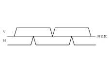
ここでは、送信APAA3及び受信APAA5が正偏波として垂直偏波Vを使用し、逆偏波として水平偏波Hを使用するものについて示しているが、垂直偏波Vと水平偏波Hは図7に示すような関係を有している。
【0011】
【発明が解決しようとする課題】
従来の移動体衛星通信装置は以上のように構成されているので、移動体の移動方向が水平方向のみに限定されれば、偏波面を補正する必要がないが、航空機やヘリコプタのように3次元的に移動する移動体に搭載された場合、アンテナビームを衛星方向に指向させても、交差偏波の偏波面にずれが発生するため、受信APAA5から受信周波数変換器6に出力される変調信号(正偏波)に逆偏波の漏れ込みが発生して、受信信号の劣化が生じる課題があった。
また、送信APAA3から出力される信号の交差偏波面がずれると、送信信号が他信号へ干渉する状況が発生する課題があった。
【0012】
この発明は上記のような課題を解決するためになされたもので、3次元的に移動する移動体に搭載された場合でも、受信信号の劣化や他信号への干渉を防止することができる移動体衛星通信装置及び移動体衛星通信方法を得ることを目的とする。
【0013】
【課題を解決するための手段】
この発明に係る移動体衛星通信装置は、アクティブフェーズドアレイアンテナにより受信された無線周波数信号に含まれる逆偏波の電力を検出する電力検出器を設け、変復調器から出力された無線周波数信号である正偏波の電力を検出し、その正偏波の電力が第2の基準電力より小さい場合、その電力検出器により検出された逆偏波の電力が第1の基準電力より大きくなると、その正偏波と逆偏波の電力に基づいてアクティブフェーズドアレイアンテナの偏波面を制御するようにしたものである。
【0014】
この発明に係る移動体衛星通信装置は、電力検出器により検出される逆偏波の電力が水平偏波信号の電力であり、制御手段により検出される正偏波の電力が垂直偏波信号の電力であるようにしたものである。
【0015】
この発明に係る移動体衛星通信装置は、電力検出器により検出される逆偏波の電力が垂直偏波信号の電力であり、制御手段により検出される正偏波の電力が水平偏波信号の電力であるようにしたものである。
【0016】
この発明に係る移動体衛星通信方法は、アクティブフェーズドアレイアンテナが無線周波数信号を受信すると、その無線周波数信号に含まれる逆偏波の電力を検出するとともに、変復調器から出力された無線周波数信号である正偏波の電力を検出し、その正偏波の電力が第2の基準電力より小さい場合、その逆偏波の電力が第1の基準電力より大きくなると、その正偏波と逆偏波の電力に基づいてアクティブフェーズドアレイアンテナの偏波面を制御するようにしたものである。
【0017】
この発明に係る移動体衛星通信方法は、逆偏波の電力が水平偏波信号の電力であり、正偏波の電力が垂直偏波信号の電力であるようにしたものである。
【0018】
この発明に係る移動体衛星通信方法は、逆偏波の電力が垂直偏波信号の電力であり、正偏波の電力が水平偏波信号の電力であるようにしたものである。
【0019】
【発明の実施の形態】
以下、この発明の実施の一形態を説明する。
実施の形態1.
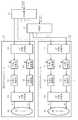
図1はこの発明の実施の形態1による移動体衛星通信装置を示す構成図であり、図において、1は情報を変復調する変復調装置、2は変復調装置1から出力された変調信号の周波数を中間周波数から無線周波数に変換する送信周波数変換器である。なお、変復調装置1と送信周波数変換器2から変復調器が構成されている。
3は送信周波数変換器2により周波数変換された変調信号(無線周波数信号)を衛星に向けて送信する送信APAA(アクティブフェーズドアレイアンテナ)、4は変調信号(逆偏波)を終端する終端器である。
【0020】
5は衛星から送信された無線周波数の変調信号(無線周波数信号)を受信する受信APAA(アクティブフェーズドアレイアンテナ)、6は受信APAA5により受信された変調信号(正偏波)の周波数を無線周波数から中間周波数に変換する受信周波数変換器、8は移動体の絶対位置を検出する機体位置センサー、9は機体位置センサー8により検出された移動体の絶対位置に基づいて送信APAA3及び受信APAA5のビーム指向方向及び偏波面を制御するアンテナ制御装置である。
【0021】
31は受信APAA5により受信された変調信号に含まれる逆偏波の電力を検出する電力検出器、32は変復調装置1から出力された変調信号(正偏波)の電力を検出し、その正偏波の電力と逆偏波の電力を考慮して偏波面を制御する偏波面制御部(制御手段)である。
図2はこの発明の実施の形態1による移動体衛星通信方法を示すフローチャートである。
【0022】
次に動作について説明する。
変復調装置1が衛星通信地球局等に送信する情報を中間周波数の変調信号に変調すると、送信周波数変換器2が変調信号の周波数を中間周波数から無線周波数に変換して、送信APAA3の垂直偏波端子に出力する。
これにより、送信APAA3から無線周波数の変調信号が衛星に向けて送信される。
【0023】
一方、受信APAA5が衛星から送信された無線周波数の変調信号を受信すると、受信周波数変換器6が受信APAA5により受信された変調信号の周波数を無線周波数から中間周波数に変換し、変復調装置1が当該変調信号を復調することにより、衛星通信地球局等から送信された情報を再生する。
【0024】
移動体衛星通信装置が移動体に搭載されている場合(図6を参照)、衛星との相対位置が時々刻々と変化するため、送信APAA3及び受信APAA5のビーム方向を常に衛星に向ける必要がある。
そこで、機体位置センサー8が移動体の絶対位置を検出すると、アンテナ制御装置9が従来例と同様に、機体位置センサー8により検出された絶対位置を示す情報と、予め設定されている衛星の位置情報とに基づいてアンテナの指向方向を計算し、送信APAA3及び受信APAA5のビーム指向性を制御する。
即ち、送信APAA3のP/S15,16と受信APAA5のP/S26,27の移相量を調整して、送信APAA3及び受信APAA5のビーム指向方向を変更する。
【0025】
しかし、移動体の絶対位置だけに基づいてビーム指向性を制御しても、航空機やヘリコプタのように3次元的に移動する移動体に搭載された場合、交差偏波の偏波面にずれが発生する。
この実施の形態1では、偏波面のずれを解消するため、下記のようにして送信APAA3のP/S15,16と受信APAA5のP/S26,27の移相量を補正する。
【0026】
即ち、受信APAA5が衛星から送信された無線周波数の変調信号を受信すると(ステップST1)、電力検出器31が受信APAA5により受信された変調信号に含まれる逆偏波(水平偏波信号)の電力を検出する(ステップST2)。
一方、偏波面制御部32は、変復調装置1から出力された信号である正偏波(垂直偏波信号)の電力を検出する(ステップST3)。
【0027】
そして、偏波面制御部32は、逆偏波の電力が第1の基準電力より大きい場合、交差偏波の偏波面にずれが発生している可能性が高いので、逆偏波電力と第1の基準電力を比較する(ステップST4)。
ただし、逆偏波の電力が第1の基準電力より大きい場合でも、正偏波の電力が第2の基準電力より大きい場合には、偏波面のずれが発生したのではなく、単に受信APAA5により受信された変調信号の電力が増加しただけの可能性が高いので、正偏波電力と第2の基準電力を比較する(ステップST5)。
【0028】
偏波面制御部32は、逆偏波の電力が第1の基準電力より大きく、かつ、正偏波の電力が第2の基準電力より小さい場合に限り、ビーム指向性(偏波面)の制御を開始する。即ち、逆偏波の電力が小さくなるようにアンテナ制御装置9を介して送信APAA3のP/S15,16と受信APAA5のP/S26,27の移相量を補正する(ステップST6)。
【0029】
以上で明らかなように、この実施の形態1によれば、受信APAA5により受信された無線周波数信号に含まれる逆偏波の電力と変復調装置1から出力された正偏波の電力を考慮して偏波面を制御するように構成したので、3次元的に移動する移動体に搭載された場合でも、受信信号の劣化や他信号への干渉を防止することができる効果を奏する。
【0030】
実施の形態2.
上記実施の形態1では、電力検出器31により検出される逆偏波の電力が水平偏波信号の電力であり、偏波面制御部32により検出される正偏波の電力が垂直偏波信号の電力であるものについて示したが、電力検出器31により検出される逆偏波の電力が垂直偏波信号の電力であり、偏波面制御部32により検出される正偏波の電力が水平偏波信号の電力であってもよい。
【0031】
【発明の効果】
以上のように、この発明によれば、アクティブフェーズドアレイアンテナにより受信された無線周波数信号に含まれる逆偏波の電力を検出する電力検出器を設け、変復調器から出力された無線周波数信号である正偏波の電力を検出し、その正偏波の電力が第2の基準電力より小さい場合、その電力検出器により検出された逆偏波の電力が第1の基準電力より大きくなると、その正偏波と逆偏波の電力に基づいてアクティブフェーズドアレイアンテナの偏波面を制御するように構成したので、3次元的に移動する移動体に搭載された場合でも、受信信号の劣化や他信号への干渉を防止することができる効果がある。また、不要な偏波面の制御を防止することができる効果がある。
【0032】
この発明によれば、電力検出器により検出される逆偏波の電力が水平偏波信号の電力であり、制御手段により検出される正偏波の電力が垂直偏波信号の電力であるように構成したので、構成の複雑化を招くことなく、偏波面のずれの発生等を検出することができる効果がある。
【0033】
この発明によれば、電力検出器により検出される逆偏波の電力が垂直偏波信号の電力であり、制御手段により検出される正偏波の電力が水平偏波信号の電力であるように構成したので、構成の複雑化を招くことなく、偏波面のずれの発生等を検出することができる効果がある。
【0034】
この発明によれば、アクティブフェーズドアレイアンテナが無線周波数信号を受信すると、その無線周波数信号に含まれる逆偏波の電力を検出するとともに、変復調器から出力された無線周波数信号である正偏波の電力を検出し、その正偏波の電力が第2の基準電力より小さい場合、その逆偏波の電力が第1の基準電力より大きくなると、その正偏波と逆偏波の電力に基づいてアクティブフェーズドアレイアンテナの偏波面を制御するように構成したので、3次元的に移動する移動体に搭載された場合でも、受信信号の劣化や他信号への干渉を防止することができる効果がある。また、不要な偏波面の制御を防止することができる効果がある。
【0035】
この発明によれば、逆偏波の電力が水平偏波信号の電力であり、正偏波の電力が垂直偏波信号の電力であるように構成したので、構成の複雑化を招くことなく、偏波面のずれの発生等を検出することができる効果がある。
【0036】
この発明によれば、逆偏波の電力が垂直偏波信号の電力であり、正偏波の電力が水平偏波信号の電力であるように構成したので、構成の複雑化を招くことなく、偏波面のずれの発生等を検出することができる効果がある。
【図面の簡単な説明】
【図1】この発明の実施の形態1による移動体衛星通信装置を示す構成図である。
【図2】この発明の実施の形態1による移動体衛星通信方法を示すフローチャートである。
【図3】従来の移動体衛星通信装置を示す構成図である。
【図4】送信APAA3の内部構成を示す構成図である。
【図5】受信APAA5の内部構成を示す構成図である。
【図6】移動体衛星通信装置が移動体に搭載されている様子を示す説明図である。
【図7】垂直偏波Vと水平偏波Hの関係を示す説明図である。
【符号の説明】
1 変復調装置(変復調器)、2 送信周波数変換器(変復調器)、3 送信APAA(アクティブフェーズドアレイアンテナ)、4 終端器、5 受信APAA(アクティブフェーズドアレイアンテナ)、6 受信周波数変換器、8 機体位置センサー、9 アンテナ制御装置、31 電力検出器、32 偏波面制御部(制御手段)。[0001]
TECHNICAL FIELD OF THE INVENTION
The present invention relates to a mobile satellite communication device and a mobile satellite communication method for compensating for cross polarization of a mobile satellite communication antenna mounted on an aeronautical vehicle such as an aircraft or a helicopter.
[0002]
[Prior art]
FIG. 3 is a block diagram showing a conventional mobile satellite communication apparatus. In the figure,
[0003]
[0004]
FIG. 4 is a configuration diagram showing the internal configuration of the transmission APAA 3. In the drawing,
[0005]
[0006]
FIG. 5 is a block diagram showing the internal configuration of the
[0007]
Next, the operation will be described.
When the modulator /
Thereby, the modulated signal of the radio frequency is transmitted from the transmitting APAA 3 to the satellite.
[0008]
On the other hand, when the receiving APAA 5 receives the modulated signal of the radio frequency transmitted from the satellite, the
[0009]
When the mobile satellite communication device is mounted on a mobile body (see FIG. 6), the relative position with respect to the satellite changes every moment, so that the beam directions of the transmitting APAA3 and the receiving APAA5 must always be directed to the satellite. .
Therefore, when the body position sensor 8 detects the absolute position of the moving body, the
That is, the phase shift amounts of the P /
[0010]
Here, the transmission APAA3 and the reception APAA5 use the vertical polarization V as the normal polarization and use the horizontal polarization H as the reverse polarization, but the vertical polarization V and the horizontal polarization H are shown in FIG. The relationship shown in FIG.
[0011]
[Problems to be solved by the invention]
Since the conventional mobile satellite communication apparatus is configured as described above, if the moving direction of the mobile body is limited only to the horizontal direction, it is not necessary to correct the polarization plane. When mounted on a moving body that moves in a three-dimensional manner, even if the antenna beam is directed toward the satellite, the polarization plane of the cross-polarized light is shifted, so that the modulation output from the reception APAA 5 to the
Further, when the cross-polarization plane of the signal output from the transmitting
[0012]
SUMMARY OF THE INVENTION The present invention has been made to solve the above-described problem, and is capable of preventing deterioration of a received signal and interference with other signals even when mounted on a moving object that moves three-dimensionally. It is an object to obtain a body satellite communication device and a mobile satellite communication method.
[0013]
[Means for Solving the Problems]
A mobile satellite communication device according to the present invention includes a power detector that detects power of reverse polarization included in a radio frequency signal received by an active phased array antenna, and is a radio frequency signaloutput from amodem. When the power of the positive polarization is detected and the power of the positive polarization is smaller than the second reference power, the power of the reverse polarization detected by the power detector becomes larger than the first reference power. The polarization plane of the active phased array antenna is controlledbased on the powers of the polarized wave and the reverse polarized wave .
[0014 ]
In the mobile satellite communication device according to the present invention, the power of the reverse polarization detected by the power detector is the power of the horizontal polarization signal, and the power of the positive polarization detected by the control unit is the power of the vertical polarization signal. It is intended to be electric power.
[0015 ]
In the mobile satellite communication device according to the present invention, the power of the reverse polarization detected by the power detector is the power of the vertical polarization signal, and the power of the positive polarization detected by the control unit is the power of the horizontal polarization signal. It is intended to be electric power.
[0016 ]
The mobile satellite communication method according to the present invention, when the active phased array antenna receives a radio frequency signal, detects the power of the reverse polarization included in the radio frequency signal, and usesthe radio frequency signal output from the modem. If the power of a certain positive polarization is detected and the power of the positive polarization is smaller than the second reference power, and if the power of the reverse polarization is larger than the first reference power, the positive polarization and the reverse polarization are detected. The polarization plane of the active phased array antenna is controlledbased on the power of the antenna.
[0017 ]
In the mobile satellite communication method according to the present invention, the power of the reverse polarization is the power of the horizontal polarization signal, and the power of the positive polarization is the power of the vertical polarization signal.
[0018 ]
In the mobile satellite communication method according to the present invention, the power of the reverse polarization is the power of the vertical polarization signal, and the power of the positive polarization is the power of the horizontal polarization signal.
[0019 ]
BEST MODE FOR CARRYING OUT THE INVENTION
Hereinafter, an embodiment of the present invention will be described.
FIG. 1 is a block diagram showing a mobile satellite communication apparatus according to
[0020 ]
[0021 ]
FIG. 2 is a flowchart showing a mobile satellite communication method according to
[0022 ]
Next, the operation will be described.
When the modulator /
Thereby, the modulated signal of the radio frequency is transmitted from the transmitting
[0023 ]
On the other hand, when the receiving
[0024 ]
When the mobile satellite communication device is mounted on a mobile body (see FIG. 6), the relative position with respect to the satellite changes every moment, so that the beam directions of the transmitting APAA3 and the receiving APAA5 must always be directed to the satellite. .
Then, when the aircraft position sensor 8 detects the absolute position of the moving object, the
That is, the phase shift amounts of the P /
[0025 ]
However, even if the beam directivity is controlled based only on the absolute position of the moving object, if it is mounted on a moving object that moves three-dimensionally, such as an aircraft or helicopter, the polarization plane of the cross-polarization will shift. I do.
In the first embodiment, the phase shift amounts of the P /
[0026 ]
That is, when the receiving
On the other hand, the polarization
[0027 ]
When the power of the reverse polarization is larger than the first reference power, the
However, even if the power of the reverse polarization is higher than the first reference power, if the power of the positive polarization is higher than the second reference power, a shift in the polarization plane does not occur, and the reception APAA5 simply determines Since there is a high possibility that the power of the received modulated signal has just increased, the positive polarization power is compared with the second reference power (step ST5).
[0028 ]
The polarization
[0029 ]
As is apparent from the above, according to the first embodiment, the power of the reverse polarization included in the radio frequency signal received by the receiving
[0030 ]
In the first embodiment, the power of the reverse polarization detected by the
[0031 ]
【The invention's effect】
As described above, according to the present invention, the power detector that detects the power of the reverse polarization included in the radio frequency signal received by the active phased array antenna is provided,and the radio frequency signal output from themodem is provided.When the power of the positive polarization is detected and the power of the positive polarization is smaller than the second reference power, the power of the reverse polarization detected by the power detector becomes larger than the first reference power. Since the polarization plane of the active phased array antenna is controlledbased on the power of the polarized wave and the reverse polarized wave, even if the antenna is mounted on a moving object that moves three-dimensionally, deterioration of the received signal and other signals may occur. This has the effect of preventing interference.In addition, there is an effect that unnecessary polarization plane control can be prevented.
[0032 ]
According to the present invention, the power of the reverse polarization detected by the power detector is the power of the horizontal polarization signal, and the power of the positive polarization detected by the control means is the power of the vertical polarization signal. With this configuration, it is possible to detect the occurrence of deviation of the polarization plane without complicating the configuration.
[0033 ]
According to the present invention, the power of the reverse polarization detected by the power detector is the power of the vertical polarization signal, and the power of the positive polarization detected by the control unit is the power of the horizontal polarization signal. With this configuration, it is possible to detect the occurrence of deviation of the polarization plane without complicating the configuration.
[0034 ]
According to the present invention, when the active phased array antenna receives a radio frequency signal, it detects the power of the reverse polarization included in the radio frequency signal, and detectsthe positive polarization of the radio frequency signal output from the modem. If the power of the positive polarization is smaller than the second reference power and the power of the reverse polarization is larger than the first reference power, the power is detected based on the power of the positive polarization and the reverse polarization. Since the configuration is such that the polarization plane of the active phased array antenna is controlled, even when the antenna is mounted on a moving object that moves three-dimensionally, there is an effect that deterioration of a received signal and interference with other signals can be prevented. .In addition, there is an effect that unnecessary polarization plane control can be prevented.
[0035 ]
According to the present invention, since the power of the reverse polarization is the power of the horizontal polarization signal and the power of the positive polarization is the power of the vertical polarization signal, without complicating the configuration, There is an effect that it is possible to detect the occurrence of the deviation of the polarization plane and the like.
[0036 ]
According to the present invention, since the power of the reverse polarization is the power of the vertical polarization signal and the power of the positive polarization is the power of the horizontal polarization signal, without complicating the configuration, There is an effect that it is possible to detect the occurrence of the deviation of the polarization plane and the like.
[Brief description of the drawings]
FIG. 1 is a configuration diagram showing a mobile satellite communication device according to a first embodiment of the present invention.
FIG. 2 is a flowchart showing a mobile satellite communication method according to
FIG. 3 is a configuration diagram showing a conventional mobile satellite communication device.
FIG. 4 is a configuration diagram showing an internal configuration of a transmission APAA3.
FIG. 5 is a configuration diagram showing an internal configuration of a reception APAA5.
FIG. 6 is an explanatory diagram showing a state where a mobile satellite communication device is mounted on a mobile object.
FIG. 7 is an explanatory diagram showing a relationship between a vertically polarized wave V and a horizontally polarized wave H.
[Explanation of symbols]
DESCRIPTION OF
Claims (6)
Translated fromJapanesePriority Applications (1)
| Application Number | Priority Date | Filing Date | Title |
|---|---|---|---|
| JP2000334848AJP3576478B2 (en) | 2000-11-01 | 2000-11-01 | Mobile satellite communication device and mobile satellite communication method |
Applications Claiming Priority (1)
| Application Number | Priority Date | Filing Date | Title |
|---|---|---|---|
| JP2000334848AJP3576478B2 (en) | 2000-11-01 | 2000-11-01 | Mobile satellite communication device and mobile satellite communication method |
Publications (2)
| Publication Number | Publication Date |
|---|---|
| JP2002141849A JP2002141849A (en) | 2002-05-17 |
| JP3576478B2true JP3576478B2 (en) | 2004-10-13 |
Family
ID=18810691
Family Applications (1)
| Application Number | Title | Priority Date | Filing Date |
|---|---|---|---|
| JP2000334848AExpired - Fee RelatedJP3576478B2 (en) | 2000-11-01 | 2000-11-01 | Mobile satellite communication device and mobile satellite communication method |
Country Status (1)
| Country | Link |
|---|---|
| JP (1) | JP3576478B2 (en) |
Cited By (1)
| Publication number | Priority date | Publication date | Assignee | Title |
|---|---|---|---|---|
| WO2023039192A1 (en)* | 2021-09-09 | 2023-03-16 | Hughes Network Systems, Llc | Multi-band radiofrequency transceiver |
Families Citing this family (8)
| Publication number | Priority date | Publication date | Assignee | Title |
|---|---|---|---|---|
| DE60316614T2 (en) | 2003-10-30 | 2008-07-17 | Mitsubishi Denki K.K. | MOBILE SATELLITE COMMUNICATION SYSTEM |
| DE60333803D1 (en)* | 2003-10-30 | 2010-09-23 | Mitsubishi Electric Corp | Airplane with an antenna device |
| US8693970B2 (en) | 2009-04-13 | 2014-04-08 | Viasat, Inc. | Multi-beam active phased array architecture with independant polarization control |
| US10516219B2 (en) | 2009-04-13 | 2019-12-24 | Viasat, Inc. | Multi-beam active phased array architecture with independent polarization control |
| US8452251B2 (en) | 2009-04-13 | 2013-05-28 | Viasat, Inc. | Preselector amplifier |
| US8817672B2 (en) | 2009-04-13 | 2014-08-26 | Viasat, Inc. | Half-duplex phased array antenna system |
| US8699626B2 (en) | 2011-11-29 | 2014-04-15 | Viasat, Inc. | General purpose hybrid |
| JP7064467B2 (en)* | 2019-04-18 | 2022-05-10 | 株式会社東芝 | Antenna device |
- 2000
- 2000-11-01JPJP2000334848Apatent/JP3576478B2/ennot_activeExpired - Fee Related
Cited By (2)
| Publication number | Priority date | Publication date | Assignee | Title |
|---|---|---|---|---|
| WO2023039192A1 (en)* | 2021-09-09 | 2023-03-16 | Hughes Network Systems, Llc | Multi-band radiofrequency transceiver |
| US12335025B2 (en) | 2021-09-09 | 2025-06-17 | Hughes Network Systems, Llc | Multi-band radiofrequency transceiver |
Also Published As
| Publication number | Publication date |
|---|---|
| JP2002141849A (en) | 2002-05-17 |
Similar Documents
| Publication | Publication Date | Title |
|---|---|---|
| JP4217711B2 (en) | Antenna device | |
| US7925232B2 (en) | Reduced cost mobile satellite antenna system using a plurality of satellite transponders | |
| AU713294B2 (en) | Multi-function interactive communications system with circularly/elliptically polarized signal transmission and reception | |
| US7113748B2 (en) | System and method for improving polarization matching on a cellular communication forward link | |
| US20100046421A1 (en) | Multibeam Antenna System | |
| JP3576478B2 (en) | Mobile satellite communication device and mobile satellite communication method | |
| JPH0211032A (en) | Up-link cross polarization compensator | |
| CN103067066B (en) | Interference rejection method for down-chain of double-antenna satellite communication system | |
| US7039357B2 (en) | Diversity coverage | |
| US20210218482A1 (en) | Apparatus And Method For Correcting Deviation Between Plurality Of Transmission Channels | |
| CN113782987A (en) | Dual-band full-airspace satellite communication phased array antenna | |
| JP2666702B2 (en) | Cross polarization compensator | |
| JP2015064291A (en) | Communication / radar antenna system | |
| JP2009159453A (en) | Wireless communication system, polarization plane adjustment method, base station, and sensor station | |
| WO2021199452A1 (en) | Transmission radio wave confirmation method, portable station device, and transmission radio wave confirmation program in satellite communication system | |
| JP3456405B2 (en) | Dual polarization space diversity radio equipment | |
| JP2007221303A (en) | Satellite communication antenna device | |
| JP6505584B2 (en) | Distributed array antenna system, distributed array controller and distributed array control method | |
| US20240333345A1 (en) | Radio communication system, transmission apparatus and reception apparatus | |
| JP2833961B2 (en) | Cross polarization compensator | |
| JP2879859B2 (en) | Multiplexed wireless device using hot standby communication method | |
| JP2973952B2 (en) | Interference wave removal method and apparatus | |
| JP2007150829A (en) | Wireless device and communication control method | |
| JP2987077B2 (en) | Synchronous relay method and apparatus for FM broadcast | |
| JP2002319814A (en) | Wireless device |
Legal Events
| Date | Code | Title | Description |
|---|---|---|---|
| TRDD | Decision of grant or rejection written | ||
| A01 | Written decision to grant a patent or to grant a registration (utility model) | Free format text:JAPANESE INTERMEDIATE CODE: A01 Effective date:20040608 | |
| A61 | First payment of annual fees (during grant procedure) | Free format text:JAPANESE INTERMEDIATE CODE: A61 Effective date:20040707 | |
| R150 | Certificate of patent or registration of utility model | Free format text:JAPANESE INTERMEDIATE CODE: R150 | |
| FPAY | Renewal fee payment (event date is renewal date of database) | Free format text:PAYMENT UNTIL: 20070716 Year of fee payment:3 | |
| FPAY | Renewal fee payment (event date is renewal date of database) | Free format text:PAYMENT UNTIL: 20080716 Year of fee payment:4 | |
| FPAY | Renewal fee payment (event date is renewal date of database) | Free format text:PAYMENT UNTIL: 20090716 Year of fee payment:5 | |
| LAPS | Cancellation because of no payment of annual fees |