JP3576015B2 - Navigation system - Google Patents
Navigation systemDownload PDFInfo
- Publication number
- JP3576015B2 JP3576015B2JP33697798AJP33697798AJP3576015B2JP 3576015 B2JP3576015 B2JP 3576015B2JP 33697798 AJP33697798 AJP 33697798AJP 33697798 AJP33697798 AJP 33697798AJP 3576015 B2JP3576015 B2JP 3576015B2
- Authority
- JP
- Japan
- Prior art keywords
- time
- facility
- input
- information
- spare
- Prior art date
- Legal status (The legal status is an assumption and is not a legal conclusion. Google has not performed a legal analysis and makes no representation as to the accuracy of the status listed.)
- Expired - Fee Related
Links
Images


Landscapes
- Instructional Devices (AREA)
- Traffic Control Systems (AREA)
Description
Translated fromJapanese【0001】
【発明の属する技術分野】
本発明は、ナビゲーションシステムに関し、特に、周辺情報を提示するナビゲーションシステムに関する。
【0002】
【従来の技術】
従来、現在位置および目的地を入力することで、現在位置,目的地周辺の地図情報および現在位置から目的地までの経路情報を表示するナビゲーションシステムに関する発明は、数多くなされている。
現在位置周辺に関する情報提供に関して言えば、例えば、特開平5−102906号公報には、移動局の位置に対して関連するサービス情報を検索し、検索結果のサービス情報を移動局に送信する技術が開示されている。これは、移動通信システムがあらかじめ備えている基地局情報によって移動局が自位置を知り、移動通信サービスセンタが集約した道路の渋滞情報または道路地図情報等から必要なサービス情報を検索し、移動局の位置情報に関連したサービス情報を移動通信サービスセンタが移動局に送信するものである。
【0003】
また、特開平6−20197号公報には、所定の施設を検索する場合に、表示されている地図の範囲内に存在するものを検索すると同時に、表示装置の地図の周辺に含まれる施設も検索する技術が開示されている。これは、表示手段に表示している地図に操作者が所望とする施設が存在しない時、ROM内の付加情報を検索するソフトウェアが駆動し、表示手段に表示されている地図の周辺に存在する所望の施設を検索し、検索結果、表示している地図のどの方向にどれだけの数の施設が存在するかを示すといったものである。
【0004】
そして、特開平10−30932号公報には、利用者がその嗜好に応じて、道路の周辺に位置する所望の施設を知ることができる車載用ナビゲーションシステムが開示されている。これは、道路周辺の施設に関し優先順位を設定し、設定した優先順位に従って記憶されている施設を検索し、検索された施設に関しての情報を表示するといったものである。
【0005】
【発明が解決しようとする課題】
上記従来技術はいずれも自位置を知り、この知った自位置をもとに、周辺の情報を入手し表示させるものである。特開平5−102906号公報記載のものでは、移動通信サービスセンタが集約した道路の渋滞情報や道路地図情報等の情報を周辺情報として用いているだけであり、このことにより、自位置を中心としたきめ細かい情報を入手することはできるが、表示されていない周辺部の情報までは分からない。また特開平6−20197号公報に記載されたものは、位置情報を基に表示手段には表示されない範囲に存在する特定の地図データを検索し、検索結果を表示手段に出力することで、周辺部も含めた範囲での所望する施設を検索できるようになっている。しかし、これも所望している施設の存在を表示範囲だけでなく周辺も含めて検索するだけであり、その施設へ行くまでの時間等はわからない。特開平10−30932号公報記載のものは、道路の周辺施設に関し、優先順位を設定し、設定された優先順位に従って記憶されている施設を検索し、結果を表示するようにしているため、ユーザにとって嗜好に従って所望の施設を検索してこれに関する情報を表示することができるようになっている。これにより、表示されている施設までの距離をおおざっぱに把握することはできる。すなわち、所定の距離の範囲内に位置する施設により高い優先順位を与えることで、所定の距離以内にあるかどうかは分かる。しかし、この発明は車の進行方向に沿って存在する施設を優先的に表示させようとするものであり、積極的に迂回することで行くことができる施設等のサービスを表示させようとするものではない。また、どのくらいの時間的余裕があれば表示されている施設に行くことができるかまではわからない。
【0006】
いずれにしても上記従来技術では、周辺情報として表示されている情報の所在地へ行くには、どのくらいの時間が必要か、逆にどのくらいの時間があれば表示されている情報(表示されていない情報も含めて)の所在地まで行けるのかが不明である。すなわち、周辺情報として表示される情報を十分に活用できているとは言えない。
【0007】
本発明では、上記問題点を解決し、どのくらいの時間的余裕があれば行くことができる施設が周辺にどのくらいあるか、また表示されている施設に行くのに要する時間を容易に知ることができるナビゲーションシステムを提供することを目的とする。
本発明の別の目的は、目的地へ行く前に時間的な余裕があればよることができる施設を簡単につかむことができるナビゲーションシステムを提供することである。
本発明のさらなる目的は、各操作者の嗜好に応じて、時間的な余裕があれば立ち寄りたい施設等を教えてくれるナビゲーションシステムを提供することである。
【0008】
請求項1に記載の発明は、基準となる任意の位置を入力し、入力した任意の位置周辺の情報を獲得し、獲得した情報を表示するナビゲーションシステムにおいて、操作者が有している余裕時間を入力する余裕時間入力手段と、入力した任意の位置から移動する際に利用できる移動手段を入力あるいは選択する移動手段入力手段と、入力した任意の位置から、該移動手段入力手段にて入力あるいは選択した移動手段を用いて、周辺情報として獲得した情報中に含まれる施設に行くまでに必要な時間を得る施設到達時間取得手段と、該施設到達時間取得手段にて取得した時間と前記余裕時間入力手段にて入力された時間とを比較する時間比較手段と、前記余裕時間入力手段にて入力した余裕時間内で複数の到達時間に区分する余裕時間分割手段を有し、区分したそれぞれの到達時間に対して前記施設到達時間取得手段にて取得した時間と比較し、前記到達時間の区分別に到達することができる施設を区別して表示するようにしたものである。
【0013】
【発明の実施の形態】
(実施例1)
図1は、本発明の第1の実施例であるナビゲーションシステムの構成を示すブロック図である。この図において、ナビゲーション装置1は、装置全体を制御するCPU2、後述する制御ソフト等が格納されているROM3、ワークエリアや入力されたデータ等が格納されるRAM4、表示部5、基準となる任意の地点を入力する位置入力部6、CD−ROM等の媒体や通信を介して地図情報を獲得する地図情報獲得部7、通信等で上記位置入力部6から入力した位置の周辺に関する情報を獲得する周辺情報獲得部8、操作する人が所有している余裕時間を入力する余裕時間入力部9、操作する人が上記位置入力部6にて入力した位置から利用することができる移動手段を入力する移動手段入力部10、上記移動手段入力部10にて入力された移動手段を用いて上記位置入力部6にて入力した位置から、上記地図情報獲得部7または、周辺情報獲得部8が獲得した施設等へ行くまでに要する時間を獲得する施設到達時間取得部11、および上記施設到達時間取得部11にて得られた施設に行くまでに必要とされる時間と余裕時間入力部9にて入力された余裕時間とを比較する時間比較部12とから構成される。
【0014】
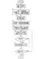
図2及び図3は、図1のナビゲーションシステムの処理動作を示すフローチャートである。例えば、このナビゲーション装置1を使って東京駅に列車の乗り継ぎに3時間余裕がある人の場合をとって、このフローチャートを用いて説明する。この人は、まず位置入力部6にて“東京駅”を、余裕時間入力部9にて“3時間”を、また移動手段入力部10にて“徒歩”を入力する(ステップS1)。ここで、移動手段としては、例えばレンタカーを借りることも考えられるが、徒歩にて移動するとした場合につき説明する。ステップS1にて入力された位置,余裕時間,移動手段をそれぞれRAM4内の位置格納部41、余裕時間格納部42、移動手段格納部43に格納する(ステップS2)。この時に、余裕時間に関しては出発地点に帰ってくる必要があるため、入力されたデータの半分の値(この例の場合は、1時間30分)を余裕時間格納部42に格納する。位置格納部41に格納されている位置を含む地図情報を地図情報獲得部7を用いて、また位置格納部41に格納されている位置周辺の情報を周辺情報獲得部8をそれぞれ用いて獲得し(ステップS3)、それぞれRAM内の獲得地図情報格納部44および獲得周辺情報格納部45に格納する(ステップS4)。ここで、地図情報とは地名や施設,道路,鉄道等が記載されている普通の地図であり、周辺情報とは、施設の所在地,主な地点からの距離および所要時間,見所,営業日等、その施設に関する情報が含まれているものであり、上記地図情報とリンク付けされているものとする。このリンク付けの手法は、既存の技術であり、情報の所在地(緯度,経度情報)等により行うことができる。この周辺情報は、移動手段格納部43に格納されている移動手段を周辺情報を獲得する時に、センターに連絡することにより、上記移動手段に応じたものがセンターから送信されてくる。次に、施設到達時間取得部11により、位置格納部41に格納されている位置から、移動手段格納部43に格納されている移動手段を用いて、周辺情報獲得部8が獲得した周辺情報中に含まれる施設までの到達時間を調べる(ステップS5)。
【0015】
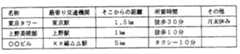
この施設到達時間取得部11の動きについて、もう少し詳細に説明する。上記周辺情報取得部8により取得した情報の例を図4に示す。この図においても明らかなように、各施設の情報が、名称,最寄り駅,最寄り駅からの距離,最寄り駅からの所要時間,その他休館日,標準閲覧時間等各施設に固有の情報から構成されている。この周辺情報を用いて、位置格納部41に格納されている位置から、移動手段格納部43に格納されている移動手段を用いた場合の各施設までの所要時間を求めていく。すなわち、各データの最寄り駅の部分が、位置格納部41に一致しているかどうかを判断する(ステップS51)。位置格納部41と最寄り駅が一致した場合(この例の場合は東京タワーのデータがこれに相当する)、最寄り駅からの所要時間を求める施設までの到達時間として返却する(ステップS52)。位置格納部41と最寄り駅が一致しない場合(この例の場合は、上野美術館や◯◯ビルのデータがこれに相当する)、通信を用いてサーバのデータベースにアクセスし、位置格納部41の位置と周辺情報データ中の最寄り駅との間の所要時間を求める(ステップS53)。求まった所要時間と、周辺情報データ中の最寄り駅から施設までの所要時間を合計する(ステップS54)。この合計を求める施設までの到達時間として返却する(ステップS55)。例えば、データベースに接続し、東京駅から上野駅までの所要時間が15分と分かった場合は、東京駅から上野美術館までの所要時間は25分(=10+15)として求まる。同様に、東京駅から××線△△駅までの所要時間が45分と分かった場合には、東京駅から○○ビルまでの所要時間は55分と(=45+10)として求まる。この時に、位置格納部に格納されている地名から最寄り駅までの所要時間に関するデータベースが無く、所要時間が求まらない場合も考えられるが、この場合は、入力された位置情報からの一番近い駅を周辺情報取得部から求め、この駅までの距離を計測し、この駅までの所要時間を計算する。この後、この駅を上記例における入力された位置と考えることにより、施設までの所要時間が求められる。
【0016】
以上の方法を周辺情報として獲得したデータ全てに対して行うことにより、位置格納部41に格納されている位置から各施設までの所要時間が求まることになる。求まった所要時間は、全てRAM4上に格納しておく、その後、求まった施設までの所要時間と余裕時間格納部42に格納されている時間とを時間比較部12にて比較を行い(ステップS6)、余裕時間格納部42に格納されている時間の方が大きい場合には、該施設に行くことができると判断し該施設を獲得地図情報格納部44に格納されている地図上に表示し(ステップS7)、余裕時間格納部42に格納されている時間の方が小さい場合には、該施設に行くことができないと判断し、その施設は表示しない。上記ステップS6及びS7をステップS5にて取得した施設全てにつき、行うことで、各ユーザの状況(余裕時間)に応じて行くことができる施設を検索し、表示することができる。
以上説明したように、余裕時間,移動手段を入力し、周辺情報と得られた施設までの所要時間を取得し、この所要時間と余裕時間とを比較することにより、余裕時間が大きいデータのみを表示するようにした為、ある地点を基準とした時に、余裕時間内で移動することができる周辺の情報が簡単に知ることができ、余裕時間を有効に活用することができるナビゲーションシステムが提供できる。
【0017】
(実施例2)
図5は、第2の実施例であるナビゲーションシステムの構成を示すブロック図である。この図は、図1のブロック図と比べて余裕時間入力部9にて入力した余裕時間を複数個に分割する余裕時間分割部13、および分割された余裕時間が格納される分割余裕時間格納部46が付加された以外は、全て図1と同じである。ここで余裕時間をいくつに分割するかについては、入力された余裕時間に応じて任意に決めるものとし、その手法については、例えば図6のように、余裕時間格納部に格納された余裕時間に応じた形のテーブルを所有しておくことで実現できる。この図において、余裕時間格納部に格納されている値(実際にユーザが入力した余裕時間の半分の値)に応じて、余裕時間をいくつに分割し、かつどのように分割するかが示されている。例えば余裕時間格納部の値が1時間〜1.5時間の場合には、分割する時間が1時間と30分の2つの値が入っているが、これは余裕時間を30分まで、1時間まで、及びそれ以上の3つに分割するように設定されていることを示している。分割する時間は、後で説明する時の便宜上、大きい方から順に格納されている。
【0018】
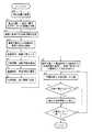
図7及び図8は、第2の実施例のナビゲーションシステムの処理動作を示すフローチャートである。実施例1の場合と同じく、東京駅にて3時間の余裕がある場合について、このフローチャートを用いて説明する。図7は、基本的には図2及び図3と同じである為、異なっている部分のみを説明する。ステップS4までは図2と同じであり、地図情報,周辺情報を格納した後、余裕時間格納部に格納されている余裕時間を、図5の余裕時間分割テーブルを参照して複数個に分割する(ステップS41)(この例の場合は、余裕時間格納部に格納されている値が1時間30分である為、30分まで、1時間まで、それ以上の3つに分割される。この分割されたそれぞれの値を分割余裕時間格納部46に格納する(ステップS42))。ここで、分割余裕時間格納部46には分割数、および分割する時間が格納されており、以下の様に制御される。位置格納部に格納されている位置から、移動手段格納部43に格納されている移動手段を用いた場合の各施設までの所要時間を求める(ステップS5)。求めた所要時間と余裕時間格納部に格納されている時間とを比較する(ステップS6)。余裕時間が大きい時は、ステップS7にて施設を地図情報中に表示し、余裕時間が小さい場合には、施設を地図情報中に表示せずにステップS86に進む。次に、上記分割余裕時間格納部46に格納された分割数を読み出し(ステップS81)、この分割数が1かどうかを判断する(ステップS82)。分割数が1の時には、余裕時間を分割しないので、ステップS86に進む。分割数が1でない時には、分割余裕時間格納部46中に格納されている分割する時間を読み出し、この分割する時間と、施設までの所要時間とを比較する(ステップS83)。分割する時間が大きい場合には、施設をステップS7にて表示したのと形態(色や線の形状等)を変えて地図上に表示する(ステップS84)。分割する時間が小さい場合は、ステップS86に進む。
【0019】
上記ステップS83,S84を、分割する時間がなくなるまで続ける(ステップS85)。次に、ステップS86にて、ステップS5にて取得した周辺情報中の全施設に関して、上記内容を行ったかどうかを判断し、行っていれば処理は終了し、行っていなければ、ステップS6にもどり、残りの施設について所要時間と余裕時間とを比較する処理を続ける。
この方法により、余裕時間が複数個に分割され、それぞれの分割された時間と施設までの所要時間とを比較することができる。ここでの比較結果を図9に表示例として示す。
以上説明したように、入力した余裕時間をさらに分割する余裕時間分割手段を設け、分割した時間に応じて、周辺情報として得られる施設までの所要時間を求めるようにした為、ある地点を基準とした時に、余裕時間内に移動できる施設の表示を、さらに細かく分割し、余裕を持っての余裕時間の活用ができるナビゲーションシステムの提供が可能になる。
【0020】
(実施例3)
図10は、本発明の第3の実施例であるナビゲーションシステムの構成を示すブロック図である。この図において、ナビゲーション装置1は、図1の基準となる任意の位置を入力する位置入力部6の代わりに、現在位置を取得する現在位置取得部14が付加されたものである。すなわち、基準となる位置を使用者が入力するかわりに、GPSや、通信しているPHSの基地局情報を用いて、現在位置を取得し、取得した現在位置を基準となる位置情報として使用するものである。
【0021】
図11は第3の実施例のナビゲーションシステムの処理動作を示すフローチャートである。このフローチャートを用いて、詳細に説明する。現在位置取得手段により、現在位置を取得する(ステップS10)。取得した現在位置情報をセンターに送信し、現在位置に一番近い駅名およびそこまでの距離を取得する(ステップS11)。取得した最寄り駅までの距離から、その最寄り駅までの所要時間を計測する(ステップS12)。この計測は、徒歩で移動する場合を考えると、徒歩では約4km/時の速度で移動できる為、最寄り駅までの距離を、4kmで割ることにより、所要時間がおおまかに求めることができる。ここで求めた現在位置から最寄り駅までの所要時間、および最寄り駅をそれぞれ最寄り駅までの所要時間格納部、最寄り駅格納部に格納する(ステップS13)。
【0022】
その後、図2および図3に示したフローと基本的に同じ制御を行い、現在位置からの余裕時間以内に移動できる施設につき、検索,表示を行う。すなわち、最寄り駅格納部に格納されている最寄り駅を図2及び図3でのユーザが入力した位置とみなし、ユーザが入力した位置へ移動するまでに、最寄り駅までの所要時間格納部に格納された所要時間だけ要する(余分にかかる)以外は、図2及び図3と同じ処理を行う為、ここでの詳細な説明は省略する。
以上説明したように、現在位置を獲得し、この獲得した現在位置を基準とした周辺情報までの所要時間を求め、入力された余裕時間とこの所要時間とを比較するようにした為、現在位置を基準として余裕時間内に移動することができる周辺の情報を簡単に知ることができるようになる。
【0023】
上記実施例において、基準となる位置のみを入力し、この位置を中心としてある施設に行くまでに要する所要時間を求め、これが余裕時間以内に往復することができるものについて表示するようにしているが、出発地と目的地を共に入力し、目的地に到達したい時刻を入れることにより、出発地から目的地へ行くまでの余裕時間が計算により求められ、また、出発地からある施設までの所要時間、ある施設から目的地までの所要時間を求め、これを合計することで出発地からある施設経由で目的地へ行くまでの所要時間が求まるため、この値と余裕時間とを比較することでも実現できる。
これにより、目的地へ行くまでの余裕時間に応じての周辺情報を検索し、簡単に知ることができるようになる。
また、ユーザが入力する情報として、個人の嗜好を入力するようにすると、この情報を活かしての施設の検索もできるようになることは言うまでもない。
これにより、余裕時間だけでなく、個人の嗜好をも考慮した周辺情報を簡単に得ることができるようになる。
【0024】
【発明の効果】
以上、詳細に説明してきたように、本発明によれば、余裕時間入力手段にて入力された余裕時間と、施設到達時間取得手段にて取得した施設に到達するのに要する時間を比較し、余裕時間が施設到達時間よりも長い場合に、その施設が表示されるようになるので、所有者が時間を有効に使用し、行ってみたい施設がひとめで分かるようになる。
【0025】
また、余裕時間が大きいデータのみを表示するようにした為、ある地点を基準とした時に、余裕時間内で移動することができる周辺の情報が簡単に知ることができ、余裕時間を有効に活用することができるナビゲーションシステムが提供できる。
【0026】
また、入力した余裕時間をさらに分割する余裕時間分割手段を設け、分割した時間に応じて、周辺情報として得られる施設までの所要時間を求めるようにした為、ある地点を基準とした時に、余裕時間内に移動できる施設の表示を、さらに細かく分割し、余裕を持っての余裕時間の活用ができるナビゲーションシステムの提供が可能になる。
【図面の簡単な説明】
【図1】本発明の第1の実施例であるナビゲーションシステムの構成を示すブロック図である。
【図2】図1のシステムの処理動作を示すフローチャートである。
【図3】図1のシステムの処理動作を示すフローチャートである。
【図4】本発明のナビゲーションシステムの周辺情報獲得部にて獲得されたデータの例を示す図である。
【図5】本発明の第2の実施例であるナビゲーションシステムの構成を示すブロック図である。
【図6】本発明の余裕時間を分割する際に用いる余裕時間分割テーブルを示す図である。
【図7】図5のシステムの処理動作を示すフローチャートである。
【図8】図5のシステムの処理動作を示すフローチャートである。
【図9】本発明の余裕時間を分割した場合の施設までの所要時間の表示例を示す図である。
【図10】本発明の第3の実施例であるナビゲーションシステムの構成を示すブロック図である。
【図11】図10のシステムの処理動作を示すフローチャートである。
【符号の説明】
1…ナビゲーション装置、2…CPU、3…ROM、4…RAM、5…表示部、6…位置入力部、7…地図情報獲得部、8…周辺情報獲得部、9…余裕時間入力部、10…移動手段入力部、11…施設到達時間取得部、12…時間比較部、13…余裕時間分割部、14…現在位置取得部、41…位置格納部、42…余裕時間格納部、43…移動手段格納部、44…獲得地図情報格納部、45…獲得周辺情報格納部、46…分割余裕時間格納部。[0001]
TECHNICAL FIELD OF THE INVENTION
The present invention relates to a navigation system, and more particularly, to a navigation system that presents peripheral information.
[0002]
[Prior art]
2. Description of the Related Art Conventionally, there have been many inventions related to a navigation system that displays a current position, map information around a destination, and route information from a current position to a destination by inputting a current position and a destination.
Regarding the provision of information on the vicinity of the current position, for example, Japanese Patent Laid-Open No. 5-102906 discloses a technique for searching for service information related to the position of a mobile station and transmitting service information of the search result to the mobile station. It has been disclosed. This is because the mobile station knows its own position based on base station information provided in advance by the mobile communication system, and the mobile communication service center searches for necessary service information from congested road information or road map information collected by the mobile communication service center. The mobile communication service center transmits service information related to the position information to the mobile station.
[0003]
Japanese Patent Laid-Open Publication No. Hei 6-20197 discloses that when searching for a predetermined facility, a facility existing within the range of the displayed map is searched at the same time as a facility included in the vicinity of the map on the display device. A technique for performing this is disclosed. This is because when a facility desired by the operator does not exist in the map displayed on the display means, software for searching for additional information in the ROM is driven and exists around the map displayed on the display means. A desired facility is searched, and the search result indicates how many facilities are present in which direction on the displayed map.
[0004]
Japanese Unexamined Patent Application Publication No. 10-30932 discloses an in-vehicle navigation system in which a user can know a desired facility located around a road according to his / her preference. This involves setting priorities for facilities around the road, searching for stored facilities according to the set priorities, and displaying information on the searched facilities.
[0005]
[Problems to be solved by the invention]
Each of the above-mentioned prior arts knows a self-location and obtains and displays surrounding information based on the known self-location. In the device described in Japanese Patent Application Laid-Open No. 5-102906, only information such as traffic congestion information and road map information collected by a mobile communication service center is used as peripheral information. Although detailed information can be obtained, it is impossible to know information on peripheral parts that are not displayed. Further, Japanese Unexamined Patent Publication No. Hei 6-20197 discloses a technique in which specific map data existing in a range not displayed on the display means is searched based on the position information, and the search result is output to the display means. It is possible to search for a desired facility in a range including the department. However, this also only searches for the presence of the desired facility not only in the display range but also in the vicinity, and does not know the time to go to the facility. Japanese Patent Application Laid-Open No. 10-30932 discloses a method of setting priorities for facilities around a road, searching for stored facilities according to the set priorities, and displaying the results. The user can search for a desired facility according to his / her preference and display information on the desired facility. This makes it possible to roughly grasp the distance to the displayed facility. That is, by giving higher priority to the facilities located within the range of the predetermined distance, it is possible to know whether the facilities are within the predetermined distance. However, the present invention is intended to preferentially display facilities existing along the traveling direction of a car, and to display services such as facilities that can be accessed by actively detouring. is not. In addition, it is not known how much time can be reached to the displayed facility.
[0006]
In any case, in the above-described conventional technology, how long is required to go to the location of the information displayed as the peripheral information, and on the contrary, how long is the displayed information (information not displayed) It is not known whether or not it is possible to go to the location. That is, it cannot be said that the information displayed as the peripheral information has been sufficiently utilized.
[0007]
According to the present invention, it is possible to solve the above-mentioned problem and easily know how much time is available to access the facilities in the vicinity and how long it takes to go to the displayed facility. It is intended to provide a navigation system.
Another object of the present invention is to provide a navigation system capable of easily grasping a facility which can be obtained if there is sufficient time before going to a destination.
A further object of the present invention is to provide a navigation system that indicates a facility or the like to visit if there is enough time in accordance with the preference of each operator.
[0008]
According to a first aspect of the present invention, there is provided a navigation system for inputting an arbitrary reference position, acquiring information around the input arbitrary position, and displaying the acquired information. Time input means for inputting, a moving means input means for inputting or selecting a moving means that can be used when moving from any input position, and a moving means input means for inputting or inputting from any input position. using a moving meansselected, the facility arrival time acquisition means for obtaining the time required to go to the facility contained in the acquired information as peripheral information, the margin time to the time acquired inthe facility arrival time acquisition unitand time comparing means for comparing thetime input by the inputmeans, the margin time dividing means for dividing into a plurality of arrival times in the margin time entered in the margin time input means And, compared to the time acquired in the facility arrival time acquisition unit for each of the arrival time obtained by dividing, in which so as to Indicate facility that can be reached by the division the arrival time.
[0013]
BEST MODE FOR CARRYING OUT THE INVENTION
(Example 1)
FIG. 1 is a block diagram showing a configuration of a navigation system according to a first embodiment of the present invention. In FIG. 1, a
[0014]
2 and 3 are flowcharts showing the processing operation of the navigation system of FIG. For example, a case where a person who has enough time to transfer trains to Tokyo Station by using this
[0015]
The movement of the facility arrival
[0016]
By performing the above method for all the data acquired as the peripheral information, the required time from the position stored in the
As described above, the user inputs the spare time and the means of transportation, obtains the peripheral information and the required time to the obtained facility, and compares the required time with the spare time, so that only the data with a large spare time can be obtained. Since it is displayed, when a certain point is set as a reference, it is possible to easily know information on the surroundings that can be moved within the spare time, and to provide a navigation system that can effectively utilize the spare time. .
[0017]
(Example 2)
FIG. 5 is a block diagram illustrating the configuration of the navigation system according to the second embodiment. This figure is different from the block diagram of FIG. 1 in that the spare
[0018]
FIGS. 7 and 8 are flowcharts showing the processing operation of the navigation system of the second embodiment. As in the case of the first embodiment, a case where there is a margin of 3 hours at Tokyo Station will be described using this flowchart. FIG. 7 is basically the same as FIG. 2 and FIG. 3, and only different parts will be described. Steps up to step S4 are the same as those in FIG. 2. After storing the map information and the peripheral information, the spare time stored in the spare time storage unit is divided into a plurality of spare times with reference to the spare time division table in FIG. (Step S41) (In the case of this example, since the value stored in the spare time storage unit is 1 hour and 30 minutes, it is divided into 30 minutes, 1 hour, and more. The obtained values are stored in the spare margin time storage unit 46 (step S42). Here, the division spare
[0019]
Steps S83 and S84 are continued until there is no time to divide (step S85). Next, in step S86, it is determined whether or not the above contents have been performed for all the facilities in the peripheral information acquired in step S5. If so, the process ends. If not, the process returns to step S6. Then, the processing for comparing the required time and the spare time for the remaining facilities is continued.
With this method, the spare time is divided into a plurality of spare times, and each divided time can be compared with the required time to the facility. The comparison result here is shown as a display example in FIG.
As described above, the spare time division means for further dividing the inputted spare time is provided, and according to the divided time, the required time to the facility obtained as the peripheral information is obtained, so that a certain point is set as a reference. Then, it is possible to provide a navigation system that can further divide the display of the facilities that can be moved within the spare time into smaller parts and use the spare time with a margin.
[0020]
(Example 3)
FIG. 10 is a block diagram showing a configuration of a navigation system according to a third embodiment of the present invention. In this figure, a
[0021]
FIG. 11 is a flowchart showing the processing operation of the navigation system of the third embodiment. This will be described in detail with reference to this flowchart. The current position is obtained by the current position obtaining means (step S10). The acquired current position information is transmitted to the center, and the station name closest to the current position and the distance therefrom are acquired (step S11). The required time to the nearest station is measured from the acquired distance to the nearest station (step S12). In this measurement, considering the case of walking on foot, since the user can move at a speed of about 4 km / hour on foot, the required time can be roughly calculated by dividing the distance to the nearest station by 4 km. The required time from the current position obtained here to the nearest station and the nearest station are stored in the required time storage unit to the nearest station and the nearest station storage unit, respectively (step S13).
[0022]
After that, basically the same control as the flow shown in FIG. 2 and FIG. 3 is performed, and a facility that can be moved within a margin time from the current position is searched and displayed. That is, regarded as a position input by the user of the nearest station stored in the nearest storage unit in FIG. 2及beauty Figure 3, before moving to the user input position, the required time storage unit to the nearest station Since the same processing as in FIGS. 2 and 3 is performed except that the stored required time is required (it takes extra time), a detailed description is omitted here.
As described above, the current position is obtained, the required time to the peripheral information based on the obtained current position is obtained, and the input margin time is compared with the required time. , The information on the surroundings that can be moved within a margin time can be easily known.
[0023]
In the above-described embodiment, only the reference position is input, the required time required to go to a certain facility around this position is determined, and the time required to return to the facility within the extra time is displayed. By entering both the departure place and the destination, and entering the time you want to reach the destination, the extra time from the departure place to the destination can be calculated and the time required from the departure place to a certain facility Calculate the required time from a certain facility to the destination, and by summing this, the required time from the departure point to the destination via the certain facility is calculated, so you canalso compare this value with the spare time realizable.
As a result, it is possible to search for the peripheral information according to the spare time before going to the destination and easily know the information.
If the user's personal information is input as information to be input by the user, it is needless to say that the facility can be searched using this information.
This makes it possible to easily obtain peripheral information in consideration of not only the spare time but also personal preferences.
[0024]
【The invention's effect】
As described above, according to the present invention, the spare time input by the spare time input means and the time required to reach the facility acquired by the facility arrival time acquiring means are compared according to the present invention, If the spare time is longer than the facility arrival time, the facility is displayed, so that the owner can effectively use the time and easily understand the facility that he or she wants to go to.
[0025]
In addition, since only data with a large spare time is displayed, it is possible to easily know information on the surrounding area that can be moved within the spare time when a certain point is used as a reference, making effective use of the spare time. A navigation system that can be provided can be provided.
[0026]
Further, provided the margin time dividing means for further dividing the margin time entered, in accordance with the dividedtime, because you determine a time required for the facility obtained asperipheral information, when based on a certain point, It is possible to provide a navigation system that can further divide the display of facilities that can be moved within the spare time into smaller parts and use the spare time with a margin.
[Brief description of the drawings]
FIG. 1 is a block diagram illustrating a configuration of a navigation system according to a first embodiment of the present invention.
FIG. 2 is a flowchart showing a processing operation of the system of FIG. 1;
FIG. 3 is a flowchart showing a processing operation of the system of FIG. 1;
FIG. 4 is a diagram showing an example of data acquired by a peripheral information acquisition unit of the navigation system according to the present invention.
FIG. 5 is a block diagram showing a configuration of a navigation system according to a second embodiment of the present invention.
FIG. 6 is a diagram showing a spare time division table used when dividing the spare time according to the present invention.
FIG. 7 is a flowchart showing a processing operation of the system of FIG. 5;
FIG. 8 is a flowchart showing a processing operation of the system of FIG. 5;
FIG. 9 is a diagram illustrating a display example of a required time to a facility when a spare time is divided according to the present invention.
FIG. 10 is a block diagram showing a configuration of a navigation system according to a third embodiment of the present invention.
FIG. 11 is a flowchart showing a processing operation of the system of FIG. 10;
[Explanation of symbols]
DESCRIPTION OF
Claims (1)
Translated fromJapanese操作者が有している余裕時間を入力する余裕時間入力手段と、
入力した任意の位置から移動する際に利用できる移動手段を入力あるいは選択する移動手段入力手段と、
入力した任意の位置から、該移動手段入力手段にて入力あるいは選択した移動手段を用いて、周辺情報として獲得した情報中に含まれる施設に行くまでに必要な時間を得る施設到達時間取得手段と、
該施設到達時間取得手段にて取得した時間と前記余裕時間入力手段にて入力された時間とを比較する時間比較手段と、
前記余裕時間入力手段にて入力した余裕時間内で複数の到達時間に区分する余裕時間分割手段を有し、
区分したそれぞれの到達時間に対して前記施設到達時間取得手段にて取得した時間と比較し、前記到達時間の区分別に到達することができる施設を区別して表示することを特徴とするナビゲーションシステム。In a navigation system that inputs an arbitrary position serving as a reference, obtains information around the input arbitrary position, and displays the obtained information,
Margin time input means for entering a margin time possessed by the operator;
A moving means input means for inputting or selecting a moving means which can be used when moving from any input position;
A facility arrival time obtaining means for obtaining a time required to go to a facility included in information acquired as peripheral information, using a moving means input or selected by the moving means input means from any input position; ,
Time comparison means for comparing the time acquired by the facility arrival time acquisition means with the time input by the margin time input means,
A margin time division unit that divides into a plurality of arrival times withinthe margin time inputby the margin time input unit,
A navigation system, wherein each of the divided arrival times is compared with the time acquired by the facility arrival time acquisition means, and the facilities which can be reached according tothe division of the arrival time aredistinguished and displayed.
Priority Applications (1)
| Application Number | Priority Date | Filing Date | Title |
|---|---|---|---|
| JP33697798AJP3576015B2 (en) | 1998-11-27 | 1998-11-27 | Navigation system |
Applications Claiming Priority (1)
| Application Number | Priority Date | Filing Date | Title |
|---|---|---|---|
| JP33697798AJP3576015B2 (en) | 1998-11-27 | 1998-11-27 | Navigation system |
Publications (2)
| Publication Number | Publication Date |
|---|---|
| JP2000163689A JP2000163689A (en) | 2000-06-16 |
| JP3576015B2true JP3576015B2 (en) | 2004-10-13 |
Family
ID=18304351
Family Applications (1)
| Application Number | Title | Priority Date | Filing Date |
|---|---|---|---|
| JP33697798AExpired - Fee RelatedJP3576015B2 (en) | 1998-11-27 | 1998-11-27 | Navigation system |
Country Status (1)
| Country | Link |
|---|---|
| JP (1) | JP3576015B2 (en) |
Cited By (1)
| Publication number | Priority date | Publication date | Assignee | Title |
|---|---|---|---|---|
| CN102189940A (en)* | 2010-03-19 | 2011-09-21 | 爱信艾达株式会社 | Driving support device, method and program |
Families Citing this family (12)
| Publication number | Priority date | Publication date | Assignee | Title |
|---|---|---|---|---|
| JP3800285B2 (en)* | 1999-03-05 | 2006-07-26 | アイシン・エィ・ダブリュ株式会社 | Navigation device and recording medium |
| JP2002183878A (en)* | 2000-12-15 | 2002-06-28 | Toshiba Corp | Pedestrian way guidance system, pedestrian way guidance service method, way guidance data collection device, and way guidance data collection method |
| JP2002260160A (en)* | 2001-02-28 | 2002-09-13 | Toshiba Corp | Road guidance method and device |
| JP3835214B2 (en)* | 2001-08-08 | 2006-10-18 | 株式会社デンソー | Drive route setting device and drive route setting program |
| JP2003139553A (en)* | 2001-11-02 | 2003-05-14 | Nippon Telegr & Teleph Corp <Ntt> | Route search method, route search device, program, and recording medium for program in consideration of detour |
| JP2004288000A (en)* | 2003-03-24 | 2004-10-14 | Toyota Motor Corp | Vehicle information providing method, vehicle information providing system, information terminal device, and center |
| JP4340912B2 (en)* | 2005-09-30 | 2009-10-07 | 株式会社デンソー | Departure guide device and departure guide program |
| JP4497178B2 (en)* | 2007-06-26 | 2010-07-07 | ソニー株式会社 | Navigation device and method for controlling navigation device |
| JP5052408B2 (en)* | 2008-05-13 | 2012-10-17 | パイオニア株式会社 | Route search device, route search method, and route search program |
| JP2010078484A (en)* | 2008-09-26 | 2010-04-08 | Zenrin Datacom Co Ltd | Visiting candidate site presentation device, visiting candidate site presentation method, and computer program |
| JP2013152498A (en)* | 2012-01-24 | 2013-08-08 | Nec Corp | Information providing system, information providing apparatus, information providing method, and program |
| WO2021181637A1 (en) | 2020-03-12 | 2021-09-16 | 日本電気株式会社 | Information processing device, information processing method, and computer-readable recording medium |
Family Cites Families (7)
| Publication number | Priority date | Publication date | Assignee | Title |
|---|---|---|---|---|
| JP2869583B2 (en)* | 1990-12-11 | 1999-03-10 | 沖電気工業株式会社 | Reservation system from vehicle |
| JPH056137A (en)* | 1991-06-27 | 1993-01-14 | Mitsubishi Electric Corp | Navigation system |
| JP3385657B2 (en)* | 1993-08-10 | 2003-03-10 | トヨタ自動車株式会社 | Car navigation system |
| JP3250421B2 (en)* | 1995-08-09 | 2002-01-28 | トヨタ自動車株式会社 | Movement plan monitoring device |
| JPH0997005A (en)* | 1995-09-29 | 1997-04-08 | Toyota Motor Corp | Movement planning system |
| JP3425323B2 (en)* | 1997-02-21 | 2003-07-14 | アルパイン株式会社 | Route search device |
| JPH10293038A (en)* | 1997-04-21 | 1998-11-04 | Honda Motor Co Ltd | Pedestrian route guidance device |
- 1998
- 1998-11-27JPJP33697798Apatent/JP3576015B2/ennot_activeExpired - Fee Related
Cited By (2)
| Publication number | Priority date | Publication date | Assignee | Title |
|---|---|---|---|---|
| CN102189940A (en)* | 2010-03-19 | 2011-09-21 | 爱信艾达株式会社 | Driving support device, method and program |
| CN102189940B (en)* | 2010-03-19 | 2015-06-03 | 爱信艾达株式会社 | Driving support device and method |
Also Published As
| Publication number | Publication date |
|---|---|
| JP2000163689A (en) | 2000-06-16 |
Similar Documents
| Publication | Publication Date | Title |
|---|---|---|
| US6424910B1 (en) | Method and system for providing related navigation features for two or more end users | |
| US6850837B2 (en) | Method and system for providing reminders about points of interests while traveling | |
| US11255673B2 (en) | Technology for sharing GPS navigation information | |
| US6208934B1 (en) | Method and system for providing walking instructions with route guidance in a navigation program | |
| US7493213B2 (en) | Single or multiple route map matching apparatus for navigation service and method thereof | |
| US6992598B2 (en) | Apparatus and method for providing travel information | |
| US6505118B2 (en) | Navigation system for land vehicles that learns and incorporates preferred navigation routes | |
| JP3576015B2 (en) | Navigation system | |
| JP2001194171A (en) | Road guidance presentation device and system | |
| JP2001349740A (en) | Parking lot guidance method and navigation device | |
| JP6506609B2 (en) | Notification system, server device and notification method | |
| JP2003044503A (en) | Information providing system, information providing apparatus, and information providing method | |
| JPH10132591A (en) | Navigation device | |
| JP2003014481A (en) | Electronic map information device | |
| JP3899946B2 (en) | Route setting method, navigation apparatus, and computer program thereof | |
| JP2004078786A (en) | Inter-vehicle communication device | |
| KR100418827B1 (en) | An apparatus and method for providing a travel guide using a public transportations | |
| JP3591456B2 (en) | Location information providing system | |
| JPH10239079A (en) | Navigation device | |
| JP2001099663A (en) | Communication type navigation device and information acquisition method thereof | |
| JP2001216409A (en) | Information provision device | |
| JP2025153251A (en) | Information processing device, information processing method, and information processing program | |
| JP2025153250A (en) | Information processing device, information processing method, and information processing program | |
| JP2002156244A (en) | Location information service device | |
| JP2025153024A (en) | Information processing device, information processing method, and information processing program |
Legal Events
| Date | Code | Title | Description |
|---|---|---|---|
| TRDD | Decision of grant or rejection written | ||
| A01 | Written decision to grant a patent or to grant a registration (utility model) | Free format text:JAPANESE INTERMEDIATE CODE: A01 Effective date:20040706 | |
| A61 | First payment of annual fees (during grant procedure) | Free format text:JAPANESE INTERMEDIATE CODE: A61 Effective date:20040706 | |
| R150 | Certificate of patent or registration of utility model | Free format text:JAPANESE INTERMEDIATE CODE: R150 | |
| FPAY | Renewal fee payment (event date is renewal date of database) | Free format text:PAYMENT UNTIL: 20070716 Year of fee payment:3 | |
| FPAY | Renewal fee payment (event date is renewal date of database) | Free format text:PAYMENT UNTIL: 20080716 Year of fee payment:4 | |
| FPAY | Renewal fee payment (event date is renewal date of database) | Free format text:PAYMENT UNTIL: 20080716 Year of fee payment:4 | |
| FPAY | Renewal fee payment (event date is renewal date of database) | Free format text:PAYMENT UNTIL: 20090716 Year of fee payment:5 | |
| FPAY | Renewal fee payment (event date is renewal date of database) | Free format text:PAYMENT UNTIL: 20100716 Year of fee payment:6 | |
| FPAY | Renewal fee payment (event date is renewal date of database) | Free format text:PAYMENT UNTIL: 20110716 Year of fee payment:7 | |
| FPAY | Renewal fee payment (event date is renewal date of database) | Free format text:PAYMENT UNTIL: 20110716 Year of fee payment:7 | |
| FPAY | Renewal fee payment (event date is renewal date of database) | Free format text:PAYMENT UNTIL: 20120716 Year of fee payment:8 | |
| FPAY | Renewal fee payment (event date is renewal date of database) | Free format text:PAYMENT UNTIL: 20120716 Year of fee payment:8 | |
| FPAY | Renewal fee payment (event date is renewal date of database) | Free format text:PAYMENT UNTIL: 20130716 Year of fee payment:9 | |
| LAPS | Cancellation because of no payment of annual fees |