JP3572943B2 - Coil type servo valve automatic control circuit - Google Patents
Coil type servo valve automatic control circuitDownload PDFInfo
- Publication number
- JP3572943B2 JP3572943B2JP16177198AJP16177198AJP3572943B2JP 3572943 B2JP3572943 B2JP 3572943B2JP 16177198 AJP16177198 AJP 16177198AJP 16177198 AJP16177198 AJP 16177198AJP 3572943 B2JP3572943 B2JP 3572943B2
- Authority
- JP
- Japan
- Prior art keywords
- servo valve
- circuit
- coil
- automatic control
- control system
- Prior art date
- Legal status (The legal status is an assumption and is not a legal conclusion. Google has not performed a legal analysis and makes no representation as to the accuracy of the status listed.)
- Expired - Lifetime
Links
Images


Landscapes
- Control Of Turbines (AREA)
- Magnetically Actuated Valves (AREA)
Description
Translated fromJapanese【0001】
【発明の属する技術分野】
本発明は、ガスタービン・蒸気タービン制御装置の冗長化された制御システムにより操作されるコイル式サーボ弁自動制御系回路におけるサーボ弁の制御性向上、緊急時における火力プラントへの影響を改善し、火力コンバインド発電プラントの信頼性向上に関する。
【0002】
【従来の技術】
従来技術として、コイル,サーボアンプ,コントローラの各コンポーネントからなる制御系を3重化してなる3コイルサーボ弁制御システムとして“多重系統制御装置”;特開昭59−85501号公報,“サーボ弁の制御装置及びその制御方法”;特開平4−22883号公報,“タービン制御装置”;特開平5−189002号公報がある。また、信頼性,メンテナンス性,視認性の高いプロセス入出力装置として“プロセス制御システム”;特開平9−198266号公報がある。
【0003】
【発明が解決しようとする課題】
上記のような従来の方式では下記のような問題があった。
【0004】
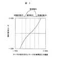
サーボ弁への操作指令は図3に示すように偏差と操作量の比例関係でしか操作ができずに、火力プラントの様々な状態において、緊急時や即応時に火力プラントの要求に追従できずに、異常診断回路が動作し、結果的にサーボコイル切離し、回路が強制動作してしまうことがあった。
【0005】
【課題を解決するための手段】
前記課題は、プロセス制御入出力装置内に操作部と検出部の偏差に応じて制御性を向上させる関数発生器,プロセス側の異常診断回路をプログラム化することによって、緊急時,即応時のサーボ弁の制御性を向上し、プロセス制御入出力装置の故障自体を異常診断回路の故障とすることにより解決される。
【0006】
【発明の実施の形態】
以下、発明の実施例を図面を用いて説明する。
【0007】
図1は、本発明の実施の形態における一例として1軸型ガスタービンコンバインド発電プラントの一実施例を示している。1軸型ガスタービンコンバインド発電プラントは、図1のようにガスタービン50,蒸気タービン60及び発電機70は同一の軸に構成されている。ガスタービン50は燃料流量調節弁20による燃料流量と入口案内翼80による圧縮空気流量の関係により出力が特定される。
【0008】
図1に示す1軸型ガスタービンコンバインド発電プラントでは、このガスタービンの廃熱を利用し、廃熱回収ボイラ40により蒸気を発生させ、発生した蒸気を蒸気タービン60へ送る構成となっている。その蒸気流量は蒸気流量加減弁30により調整される。これらは、制御装置10にて、自動制御が行われている。
【0009】
また、コイル式サーボ弁の故障,差動トランスの故障,サーボ弁ドライバーのハードウェア故障等の単一故障については、故障診断回路により検知が可能であるが、故障診断回路自体の故障については、検知することができず、仮に故障診断回路と前述の故障が複合して発生した場合には、火力プラントへ多大の影響を与えてしまう可能性があった。公共性の高い事業用火力プラントにおいては、どの様な故障モードにおいても、システム信頼性を高い水準に維持する必要があり、火力コンバインド発電プラントにおいて、主制御に係わっているサーボ弁への操作指令を突変させる要因であるコイル式サーボ弁自動制御系回路の故障診断回路の故障検知は、必須であった。
【0010】
上記のような構成としたときに、制御装置10として主に操作をしなければならないものは、燃料流量調節弁20,入口案内翼80及び蒸気加減弁30となる。これらのサーボ弁はフィードバック制御を行っており、発電プラントの出力を安定させるために、各サーボ弁への操作指令の正確さ、高速な応答性が要求され、また、冗長化されたフィードバック制御系の1系異常時においても、プラント運転継続するなど、フィードバック制御系の異常監視回路の高信頼性も維持する必要がある。
【0011】
サーボ弁の制御性を向上させるために、図2に示すようにサーボ弁ドライバーとサーボコイル切離し回路の間に緊急時・即応時に制御性を向上させる目的で、関数発生器220を設置する。この関数発生器の動特性は図3に示すように、火力プラント定常運転時には通常通りの操作量をサーボ弁へ出力し、緊急時(火力プラント保護的動作時)には、サーボ弁ドライバー130のゲイン機能を十分活用するように、高ゲインを与え、サーボ弁を高速に開閉動作を行うようにする。これにより、火力プラント異常時に速やかに要求されるサーボ弁開度へ移行ができ、コイル式サーボ弁自動制御系回路、すなわち、ガスタービン・蒸気タービン制御装置の制御性が向上できる。
【0012】
しかし、前記の関数発生器の設置には問題があった。従来のコイル式サーボ弁自動制御回路のフィードバック系は即応性が求められていたため、ハードウエアにて構成されていた。図2内に示す位置に関数発生器220を設置すると大きく応答時間遅れが発生し、制御性の劣化が懸念されるため実現できなかった。
【0013】
しかし、本発明では図4の230に示す範囲をプロセス制御入出力装置内に不揮発性書換可能型メモリ素子にソフトウェアを格納し、関数発生器220を図4内の示す位置に設置し、高速にフィードバック系を演算することにより解決される。フィードバック系の回路を不揮発性書換可能型メモリ素子にソフトウェアを格納に伴い、プロセス側の異常監視回路160,170,180も不揮発性書換可能型メモリ素子にソフトウェアを格納を行う。
【0014】
この異常診断回路自体も高速に監視を行わなければならなかったため、従来はハードウェアにて構成されていたが、プロセス制御入出力装置が高速演算が可能なため異常監視回路の不揮発性書換可能型メモリ素子にソフトウェア格納が実現できる。
【0015】
また、このプロセス制御入出力装置230はオンラインによるモニタが可能であり、時々刻々とフィードバック系の制御状態が監視できる。
【0016】
フィードバック系回路の不揮発性書換可能型メモリ素子にソフトウェアを格納により、従来、サーボ弁ドライバーのゲイン、異常監視回路の設定値は可変抵抗によりモニターリレーの設定を行っていたものが、ディジタル値により設定が可能となる。また、異常監視回路の故障の定義自体がプロセス制御入出力装置の故障とすることができるため、従来の異常監視回路の故障検出が困難であったのに対して、本発明の異常監視回路、すなわち、プロセス制御入出力装置の故障時にはワンボードマイコンのハードウェア自体の異常監視により、アナログ出力,ディジタル出力のレジスタホールド/クリアが選択可能となる。よって、プロセス制御入出力装置異常時には出力が不定となることがないため、冗長化されたシステムに速やかに、移行が可能となる。これにより、火力プラントの出力を突辺させる要因がなくなる。
【0017】
コイル式サーボ弁自動制御系回路のフィードバック系の不揮発性書換可能型メモリ素子にソフトウェアを格納による効果は、次の点もあげられる。従来ハードウェアにて構成されていたフィードバック系には多数の調整項目(可変抵抗)があり、サーボ弁の特性に合わせた調整はかなり困難であった。不揮発性書換可能型メモリ素子にソフトウェアを格納を行うことにより設定値は、ディジタル値とすることはできるが、不揮発性書換可能型メモリ素子には書込み回数の制限,高速に制御しなければならないフィードバック系では、書込み時間にも問題があるため、図4のようにオンラインチューニングが可能である調整制御コントローラ100にサーボ弁操作量微調整項目250を設置し、プロセス制御入出力装置内230にて、サーボ弁操作量240と調整項目を掛け合わせる調整回路260により、高速フィードバック系のオンラインチューニングを可能にしている。
【0018】
この設定値のディジタル化により、火力プラントで定期検査毎に調整していた調整項目(経年変化により精度が劣化していた)がディジタル値になることで、信頼性向上,工数低減に寄与することになる。
【0019】
これまで述べた内容を待機冗長2重系システムでまとめると下記の如くなる。フィードバック系の調整時には、サーボ弁操作量微調整項目250によりサーボ弁ドライバーのゲイン調整を行い、オンラインチューニングによるマンマシン性の向上,保守性向上を図る。
【0020】
また、ネットワークにより接続されたA系システム270とB系システム280は互いに冗長不均衡を是正する処理を行っており、A系を主系にして火力プラントの運転を行い、A系のプロセス入出力装置230が異常になると、速やかにA系の出力はプロセス入出力装置230のレジスタホールド/クリア処理が行われて、B系システムに移行される。
【0021】
また、緊急時(操作量と実サーボ弁開度の偏差大の時等)には関数発生器220によりサーボ弁に高ゲインが与えられ、サーボ弁を高速に操作する。このようなシステムを構築することにより、火力プラントの信頼性向上を図ることができる。
【0022】
【発明の効果】
本発明により、ガスタービン・蒸気タービン制御装置の冗長化された制御システムにより操作されるコイル式サーボ弁自動制御系回路におけるサーボ弁の制御性向上,プロセス側の異常監視回路の信頼性の向上,調整項目のディジタル化により保守性の向上、また、異常監視回路自体の故障時における火力プラントへの影響を改善し、火力コンバインド発電プラントの信頼性向上が可能となる。
【図面の簡単な説明】
【図1】本発明の実施例である1軸型ガスタービンコンバインド発電プラントの構成図。
【図2】本発明の関数発生器を設置した例を示すブロック図。
【図3】本発明の関数発生器の特性図。
【図4】本発明の待機冗長2重化システム2コイルサーボ弁への実施例を示す構成図。
【符号の説明】
10…ガスタービン・蒸気タービン制御装置、20…コイル式サーボ弁(燃料流量調節弁)、30…コイル式サーボ弁(蒸気加減弁)、40…廃熱回収ボイラ、50…ガスタービン、60…蒸気タービン、70…発電機、80…入口案内翼、100…調整制御コントローラ、110…サーボ弁操作指令、120…サーボ弁実開度、130…サーボ弁ドライバー、140…サーボコイル、150…差動トランス、160…サーボコイル異常診断回路、170…サーボ弁ドライバー異常診断回路、180…差動トランス異常診断回路、190…サーボコイル切離し回路、200…選択回路(2重系切替スイッチ)、210…高値選択回路、220…関数発生器、230…プロセス制御入出力装置、240…サーボ弁操作量、250…サーボ弁操作量微調整項目、260…調整回路、270…A系システム、280…B系システム。[0001]
TECHNICAL FIELD OF THE INVENTION
The present invention improves the controllability of a servo valve in a coil type servo valve automatic control system circuit operated by a redundant control system of a gas turbine / steam turbine control device, and improves the effect on a thermal power plant in an emergency. It relates to improving the reliability of thermal power plants.
[0002]
[Prior art]
As a prior art, a three-coil servo valve control system in which a control system composed of components of a coil, a servo amplifier, and a controller is tripled is referred to as a "multiple system controller"; Japanese Patent Application Laid-Open No. S59-85501; Japanese Patent Application Laid-Open No. Hei 4-229883, "Turbine Control Device"; Japanese Patent Application Laid-Open No. Hei 5-189002. As a process input / output device having high reliability, maintainability, and visibility, there is a "process control system";Japanese Patent Application Laid-OpenNo.9-198266 .
[0003]
[Problems to be solved by the invention]
The conventional method as described above has the following problems.
[0004]
As shown in FIG. 3, the operationcommand to the servo valve can be operated only in a proportional relationship between the deviation and the operation amount, and in various states of the thermal power plant, it cannot follow the demand of the thermal power plant in an emergency or prompt response. In some cases, the abnormality diagnosis circuit operates, resulting in disconnection of the servo coil and forced operation of the circuit.
[0005]
[Means for Solving the Problems]
The above problem is solved by programming a function generator for improving controllability in accordance with a deviation between the operation unit and the detection unit and an abnormality diagnosis circuit on the process side in the process control input / output device, so that a servo in an emergency or a quick response can be realized. The problem is solved by improving the controllability of the valve and making the failure of the process control input / output device itself a failure of the abnormality diagnosis circuit.
[0006]
BEST MODE FOR CARRYING OUT THE INVENTION
Hereinafter, embodiments of the present invention will be described with reference to the drawings.
[0007]
FIG. 1 shows an example of a single-shaft gas turbine combined power generation plant as an example of an embodiment of the present invention. In the single-shaft gas turbine combined power generation plant, as shown in FIG. 1, the
[0008]
In the single-shaft gas turbine combined power generation plant shown in FIG. 1, the waste heat of the gas turbine is used to generate steam by the waste
[0009]
In addition, a single failure such as a failure of a coil-type servo valve, a failure of a differential transformer, and a failure of a servo valve driver hardware can be detected by a failure diagnosis circuit. If the failure cannot be detected and the failure diagnosis circuit and the above failure occur in combination, there is a possibility that the thermal power plant will be greatly affected. It is necessary to maintain a high level of system reliability in any type of failure mode in a business-use thermal power plant with high publicity, and in a thermal combined power generation plant, an operation command to a servo valve related to the main control is required. It is indispensable to detect a failure in the failure diagnosis circuit of the coil-type servo valve automatic control system, which is a factor that causes a sudden change in the temperature.
[0010]
In the above configuration, the main devices that must be operated as the
[0011]
In order to improve the controllability of the servo valve, a
[0012]
However, there was a problem with the installation of the function generator. The feedback system of the conventional coil-type servo valve automatic control circuit has been required to be responsive, and thus has been configured by hardware.If the
[0013]
However, in the present invention, the range indicated by 230 in FIG. 4 is stored in a nonvolatile rewritable memory element in the process control input / output device, and the
[0014]
Conventionally, the abnormality diagnosis circuit itself had to be monitored at high speed. Therefore, conventionally, the abnormality diagnosis circuit was configured by hardware. However, since the process control input / output device can perform high-speed operations, the abnormality monitoring circuit is a nonvolatile rewritable type. Software storage can be realized in the memory element.
[0015]
Further, the process control input /
[0016]
The software is stored in the nonvolatile rewritable memory element of the feedback circuit, so that the gain of the servo valve driver and the setting value of the abnormality monitoring circuit, which used to be the setting of the monitor relay by a variable resistor, are now set by the digital value. Becomes possible. Further, since the failure itself of the abnormality monitoring circuit can be regarded as a failure of the process control input / output device, it is difficult to detect the failure of the conventional abnormality monitoring circuit. That is, when the process control input / output device fails, the analog output and digital output register hold / clear can be selected by monitoring the abnormality of the hardware of the one-board microcomputer. Therefore, when the process control input / output device is abnormal, the output does not become unstable, so that it is possible to promptly shift to a redundant system. Thus, there is no factor that causes the output of the thermal power plant to protrude.
[0017]
The effect of storing the software in the nonvolatile rewritable memory element of the feedback system of the coil-type servo valve automatic control system circuit also has the following effects. Conventionally, a feedback system composed of hardware has a large number of adjustment items (variable resistances), and it is quite difficult to adjust the characteristics according to the characteristics of the servo valve. By storing software in the nonvolatile rewritable memory element, the set value can be set to a digital value. However, in the nonvolatile rewritable memory element, the number of times of writing is limited, and feedback must be performed at high speed. In the system, since there is also a problem with the writing time, as shown in FIG. 4, a servo valve operation amount
[0018]
By digitizing the set values, the adjustment items that had been adjusted for each periodic inspection at the thermal power plant (the accuracy had deteriorated due to aging) became digital values, contributing to improved reliability and reduced man-hours. become.
[0019]
The contents described so far are summarized as follows in a standby redundant dual system. At the time of adjusting the feedback system, the gain of the servo valve driver is adjusted by the servo valve operation amount
[0020]
The
[0021]
In an emergency (when the deviation between the operation amount and the actual servo valve opening is large), a high gain is given to the servo valve by the
[0022]
【The invention's effect】
According to the present invention, the controllability of a servo valve in a coil type servo valve automatic control system circuit operated by a redundant control system of a gas turbine / steam turbine control device is improved, and the reliability of a process side abnormality monitoring circuit is improved. Digitization of the adjustment items improves maintainability, improves the effect on the thermal power plant when the abnormality monitoring circuit itself fails, and improves the reliability of the thermal combined power plant.
[Brief description of the drawings]
FIG. 1 is a configuration diagram of a single-shaft gas turbine combined power generation plant according to an embodiment of the present invention.
FIG. 2 is a block diagram showing an example in which a function generator according to the present invention is installed.
FIG. 3 is a characteristic diagram of the function generator according to the present invention.
FIG. 4 is a configuration diagram showing an embodiment of a standby redundant dual system with two coil servo valves according to the present invention;
[Explanation of symbols]
DESCRIPTION OF
Claims (1)
Translated fromJapanese前記フィードバック系制御のサーボ弁操作部とサーボ弁開度検出部の突き合わせ回路の後段に、操作部と検出部の偏差に応じて動作する関数発生器を設置することを特徴とするコイル式サーボ弁自動制御系回路。In the automatic control system circuit of the coil type servo valve of the thermal power plant, the function generator is used as the process control input / output as the matching circuitof the servo valve operation part and the servo valve opening detection part of the feedback system control requiring high-speed response.The software is stored in a microprocessor inside the operation, the software is stored in a nonvolatile rewritable memory element, and the output selection circuit and the servo valve driver of the redundant control system are constituted by hardware. ,
A coil-type servo valve, wherein a function generator that operates according to a deviation between the operation unit and the detection unit is provided at a stage subsequent to a matching circuit between the servo valve operation unit and the servo valve opening detection unit of the feedback system control. Automatic control system circuit.
Priority Applications (1)
| Application Number | Priority Date | Filing Date | Title |
|---|---|---|---|
| JP16177198AJP3572943B2 (en) | 1998-06-10 | 1998-06-10 | Coil type servo valve automatic control circuit |
Applications Claiming Priority (1)
| Application Number | Priority Date | Filing Date | Title |
|---|---|---|---|
| JP16177198AJP3572943B2 (en) | 1998-06-10 | 1998-06-10 | Coil type servo valve automatic control circuit |
Publications (2)
| Publication Number | Publication Date |
|---|---|
| JPH11351430A JPH11351430A (en) | 1999-12-24 |
| JP3572943B2true JP3572943B2 (en) | 2004-10-06 |
Family
ID=15741599
Family Applications (1)
| Application Number | Title | Priority Date | Filing Date |
|---|---|---|---|
| JP16177198AExpired - LifetimeJP3572943B2 (en) | 1998-06-10 | 1998-06-10 | Coil type servo valve automatic control circuit |
Country Status (1)
| Country | Link |
|---|---|
| JP (1) | JP3572943B2 (en) |
Families Citing this family (1)
| Publication number | Priority date | Publication date | Assignee | Title |
|---|---|---|---|---|
| CN115267405A (en)* | 2022-08-31 | 2022-11-01 | 华能湖南岳阳发电有限责任公司 | A convenient electro-hydraulic servo valve detection device |
- 1998
- 1998-06-10JPJP16177198Apatent/JP3572943B2/ennot_activeExpired - Lifetime
Also Published As
| Publication number | Publication date |
|---|---|
| JPH11351430A (en) | 1999-12-24 |
Similar Documents
| Publication | Publication Date | Title |
|---|---|---|
| US4087860A (en) | System for multi-mode control of a boiler feedpump turbine | |
| EP0081377B1 (en) | Control systems for power plant feedwater systems | |
| US4096699A (en) | Auxiliary manual turbine controller | |
| JP3572943B2 (en) | Coil type servo valve automatic control circuit | |
| GB1560523A (en) | System to control low pressure turbine temperature | |
| US4679151A (en) | Control for a limiting device | |
| JPH0367028A (en) | Control apparatus of gas turbine engine | |
| JP2684866B2 (en) | Servo valve control method | |
| US4368773A (en) | Boiler feed pump turbine control system | |
| JP2645103B2 (en) | Geothermal steam turbine bypass controller | |
| JP2509612B2 (en) | Bypass controller | |
| JP3477538B2 (en) | Turbine control device | |
| JP2730372B2 (en) | Turbine control device | |
| JP2549195B2 (en) | Auxiliary steam supply method for combined cycle power plant | |
| JPH0830323A (en) | Control method and control device | |
| JP3747253B2 (en) | Thermal power plant protection system | |
| JPH0318082B2 (en) | ||
| JPS63290302A (en) | Boiler plant automatic control device | |
| JPH0122521B2 (en) | ||
| JPH0814012A (en) | Control device for composite plant | |
| JPS637247B2 (en) | ||
| JPH0339165B2 (en) | ||
| JPH04262004A (en) | Run-back method in electric system failure | |
| JPS62291402A (en) | Load backup method upon rapid reduction in system frequency | |
| JPH01277608A (en) | Load control for power generation plant |
Legal Events
| Date | Code | Title | Description |
|---|---|---|---|
| TRDD | Decision of grant or rejection written | ||
| A01 | Written decision to grant a patent or to grant a registration (utility model) | Free format text:JAPANESE INTERMEDIATE CODE: A01 Effective date:20040608 | |
| A61 | First payment of annual fees (during grant procedure) | Free format text:JAPANESE INTERMEDIATE CODE: A61 Effective date:20040621 | |
| FPAY | Renewal fee payment (event date is renewal date of database) | Free format text:PAYMENT UNTIL: 20070709 Year of fee payment:3 | |
| FPAY | Renewal fee payment (event date is renewal date of database) | Free format text:PAYMENT UNTIL: 20080709 Year of fee payment:4 | |
| FPAY | Renewal fee payment (event date is renewal date of database) | Free format text:PAYMENT UNTIL: 20080709 Year of fee payment:4 | |
| FPAY | Renewal fee payment (event date is renewal date of database) | Free format text:PAYMENT UNTIL: 20090709 Year of fee payment:5 | |
| FPAY | Renewal fee payment (event date is renewal date of database) | Free format text:PAYMENT UNTIL: 20090709 Year of fee payment:5 | |
| FPAY | Renewal fee payment (event date is renewal date of database) | Free format text:PAYMENT UNTIL: 20100709 Year of fee payment:6 | |
| FPAY | Renewal fee payment (event date is renewal date of database) | Free format text:PAYMENT UNTIL: 20100709 Year of fee payment:6 | |
| FPAY | Renewal fee payment (event date is renewal date of database) | Free format text:PAYMENT UNTIL: 20110709 Year of fee payment:7 | |
| FPAY | Renewal fee payment (event date is renewal date of database) | Free format text:PAYMENT UNTIL: 20110709 Year of fee payment:7 | |
| FPAY | Renewal fee payment (event date is renewal date of database) | Free format text:PAYMENT UNTIL: 20120709 Year of fee payment:8 | |
| FPAY | Renewal fee payment (event date is renewal date of database) | Free format text:PAYMENT UNTIL: 20130709 Year of fee payment:9 | |
| EXPY | Cancellation because of completion of term |