JP3571601B2 - Friction stir welding method - Google Patents
Friction stir welding methodDownload PDFInfo
- Publication number
- JP3571601B2 JP3571601B2JP2000042290AJP2000042290AJP3571601B2JP 3571601 B2JP3571601 B2JP 3571601B2JP 2000042290 AJP2000042290 AJP 2000042290AJP 2000042290 AJP2000042290 AJP 2000042290AJP 3571601 B2JP3571601 B2JP 3571601B2
- Authority
- JP
- Japan
- Prior art keywords
- face plate
- friction stir
- backing
- stir welding
- face
- Prior art date
- Legal status (The legal status is an assumption and is not a legal conclusion. Google has not performed a legal analysis and makes no representation as to the accuracy of the status listed.)
- Expired - Fee Related
Links
Images


Classifications
- B—PERFORMING OPERATIONS; TRANSPORTING
- B23—MACHINE TOOLS; METAL-WORKING NOT OTHERWISE PROVIDED FOR
- B23K—SOLDERING OR UNSOLDERING; WELDING; CLADDING OR PLATING BY SOLDERING OR WELDING; CUTTING BY APPLYING HEAT LOCALLY, e.g. FLAME CUTTING; WORKING BY LASER BEAM
- B23K20/00—Non-electric welding by applying impact or other pressure, with or without the application of heat, e.g. cladding or plating
- B23K20/12—Non-electric welding by applying impact or other pressure, with or without the application of heat, e.g. cladding or plating the heat being generated by friction; Friction welding
- B23K20/122—Non-electric welding by applying impact or other pressure, with or without the application of heat, e.g. cladding or plating the heat being generated by friction; Friction welding using a non-consumable tool, e.g. friction stir welding
- B23K20/1245—Non-electric welding by applying impact or other pressure, with or without the application of heat, e.g. cladding or plating the heat being generated by friction; Friction welding using a non-consumable tool, e.g. friction stir welding characterised by the apparatus
- B—PERFORMING OPERATIONS; TRANSPORTING
- B23—MACHINE TOOLS; METAL-WORKING NOT OTHERWISE PROVIDED FOR
- B23K—SOLDERING OR UNSOLDERING; WELDING; CLADDING OR PLATING BY SOLDERING OR WELDING; CUTTING BY APPLYING HEAT LOCALLY, e.g. FLAME CUTTING; WORKING BY LASER BEAM
- B23K2101/00—Articles made by soldering, welding or cutting
- B23K2101/04—Tubular or hollow articles
- B23K2101/045—Hollow panels
Landscapes
- Engineering & Computer Science (AREA)
- Mechanical Engineering (AREA)
- Pressure Welding/Diffusion-Bonding (AREA)
- Joining Of Building Structures In Genera (AREA)
Description
Translated fromJapanese【0001】
【発明の属する技術分野】
本発明は、中空材の摩擦攪拌接合方法に関するものである。例えば、鉄道車両や航空機、建築物等に使用されるアルミニウム合金製中空押し出し形材の摩擦攪拌接合に好適である。
【0002】
【従来の技術】
摩擦攪拌接合方法は、接合部に挿入した丸棒(回転工具という)を回転させながら接合線に沿って移動させ、接合部を発熱、軟化させ、塑性流動させ、固相接合する方法である。回転工具は、接合部に挿入する小径部と、外部に位置する大径部とからなる。小径部と大径部は同軸である。小径部と大径部との境は接合部に若干挿入されている。摩擦攪拌接合方法による接合は中空押し出し形材に適用されている。これは特開平09−309164号公報(EP0797043A2)に示されている。
【0003】
【発明が解決しようとする課題】
回転工具による摩擦攪拌接合の際は、被接合部材に大きな荷重が作用する。このため、中空形材を接合する場合は、接合部にリブを設け、前記荷重をこのリブで支えるようにしている。このため、形材の重量が大きくなり、鉄道車両や航空機のような軽量化を目指している分野において重量増は大きな問題となる。本発明の目的は、この重量増加の減少を目的とするところにある。
【0004】
【課題を解決するための手段】
上記目的は、第1の形材の一方の面板の端部が、他方の面板の端部よりも隣接した形材側へ突出しており、前記第2の形材の一方の面板の端部が、他方の面板の端部よりも隣接した形材側へ突出している中空形材であって、前記第1の形材の一方の面板の端部と前記第2の形材の一方の面板の端部とを突き合わせて、該第1の形材および第2の形材を架台に載せ、
付き合わせた前記一方の面板の端部同士を、他方の面板側より摩擦攪拌接合し、次に、前記第1の形材の他方の面板の端部と、前記第2の形材の他方の面板の端部との間に接続材を配置し、前記第1の形材および第2の形材のそれぞれの一方の面板とそれぞれ他方の面板との間に裏座を配置し、前記裏座は前記各一方の面板に対して前記各他方の面板の端部と接続材の端部を支持しており、前記各他方の面板の端部と前記接続材の端部を摩擦攪拌接合し、この摩擦攪拌接合の際に、接合加工位置に前記裏座を接合加工速度に同期させて接合方向に移動させることによって達成できる。
【0005】
【発明の実施の形態】
本発明の一実施例を図1から図4により説明する。鉄道車両の車体100は、側面を構成する側構体101、屋根を構成する屋根構体102、床を構成する台枠103、構体の端部を構成する妻構体104からなっている。側構体101、屋根構体102、台枠103はそれぞれ複数の押し出し形材を接合して構成している。この形材はその長手方向を車体の長手方向に向けて並べている。形材は中空形材である。側構体101を構成している中空押し出し形材(以下、単に形材という)10、20の接合方法について説明する。他の箇所、他の構体を構成している部位についても同様である。
【0006】
形材10、20は、二枚の面板11、12、21、22と、この二枚の面板を接続する複数のリブ13、14、23、24から構成されている。二枚の面板11、12、21、22は実質的に平行である。リブ13、14、23、24は傾斜している。リブ13、23、14、24をトラス状に配置している。
【0007】
車体100の外面に位置する面板12、22の端部は車内側の面板11、21の端部よりも隣接する形材20、10側に突出している。この突出した端部の面板を面板(接合部面板)12b、22bと呼ぶ。面板12b、22bの板厚は他の部分の面板12、22の板厚よりも厚い。面板12b、22bの端部には上方に突出する凸部12c、22cがある。凸部12c、22cを含めた面板12b、22bの端部は突き合わせられ、摩擦攪拌接合されている。
【0008】
2つの凸部12c、22cを合わせた幅は回転工具の大径部の径よりも大きい。形材10、20を突き合わせて接合する際に、回転工具の大径部とその先端の小径部との境は、面板12b、22bの上面よりも上方の凸部12c、22c内に位置する。
【0009】
面板11の端部と面板21の端部とは接続材30を介して接続される。面板11の端部には凹部がある。凹部は車内側および端部側に開放している。凹部を構成するために端部側に突出片16が突出している。面板11の端部には上方に突出する凸部17がある。凸部17を含む面板11の端部に接続材30の端部を突き合わせている。また、接続材30の端部は突出片16に重なっている。前記突き合わせた部分を上方から摩擦攪拌接合している。この摩擦攪拌接合する位置は面板12bの上方にある。
【0010】
面板11と接続材30との突き合わせ部(摩擦攪拌接合する位置)、すなわち面板11から突出片16に至る角部は面板12bの上方にある。接続材30の端部にも凸部31がある。2つの凸部17、31を合わせた幅は回転工具の大径部の径よりも大きい。回転工具の大径部の挿入位置は面板12b、22bの突き合わせ部の場合と同様である。
【0011】
面板21の端部には凹部がある。凹部は車内側および端部側に開放している。凹部を構成するために端部側に突出片26が突出している。接続材30の端部は突出片26に重なっている。この重ねた部分を摩擦攪拌接合している。この摩擦攪拌接合の位置は面板22bの上方にある。突出片26の上面から面板21の上面へ連なる部分は傾斜している。これは接続材30と面板21とを溶接する場合の開先となる。突出片16、26の凹み量は接続材30の厚さに同一である。接続材30、面板11、21の上面が同一面になるようにする。
【0012】
面板21側の接続材30の端部には上方に突出する凸部32がある。凸部32の幅は回転工具の大径部の径よりも大きい。凸部32の幅の中心にはV状の溝33がある。溝33を光学式センサーで検出して溝33の位置に回転工具を誘導する。突き合わせ部の接合は突き合わせ部の位置を検出して突き合わせ部に回転工具を誘導する。回転工具の大径部の挿入量は面板12b、22bの突き合わせ部の場合と同様である。
【0013】
接続材30を接合する際には、2つの形材10、20の端部が構成する空間内に裏座210を配置する。裏座210は面板12b、22bに載っている。裏座210の上面は接合部の下方に位置している。裏座210の高さは面板12b、22bの上面から突出片16、26の下面までの高さよりも小さい。両者の隙間は大きくない。突出片16、26の下方に裏座210の上面が位置する。摩擦攪拌接合の位置(突き合わせ部(接続材30の端部)、溝33)の下方に、裏座210、および面板12b、22bがある。これによって、接続材30の両端を同時に接合しない場合でも裏座210が転倒するようなことがないものである。裏座210を配置する空間は接合部の裏面にあるといえる。
【0014】
摩擦攪拌接合の手順を説明する。まず、形材10、20を架台200に載せて固定する。面板11、21が上方で、面板12、22が下方である。面板12b、22bは突き合わせる。
【0015】
次に、面板12b、22bの上方の形材10、20の間の空間を用いて上方から摩擦攪拌接合を行う。つまり、上方から回転工具を突き合わせ部に挿入して摩擦攪拌接合を行う。面板12b、22bには凸部11c、22cがあるので、突き合わせ部の隙間は埋められる。面板12b、22bの下面は実質的に平に接合する。前記空間は、面板12b、22b、リブ13、23、面板11、21から構成される。
【0016】
この摩擦攪拌接合の際、接合によって生じるバリおよび凸部12c、22cを切削する。回転工具は大径部の半径方向の外面に刃を設置している。この刃によってバリを切削する。また、凸部12c、22cの上部を切削する。次に、この切削した切り子を除く。
【0017】
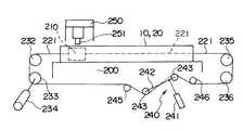
次に、形材10、20の端部が構成する空間に裏座210を配置する。図2において、左端から右端に向けて接合するとする。形材10、20の左端よりも外に、裏座210があるので、これを手で持って形材10、20の左端の面板12b、22bに載せる。裏座210の左端には左端のチエン221が連結されている。裏座210をロープを介して手で引っ張り、右端に向けて移動させる。左端のチエン221は形材10、20の端部の空間に入る。裏座210が右端に移動すると、右端のチエン221を裏座210の右端に連結する。
【0018】
前記空間の左右の延長線上にはそれぞれスプロケット232、235がある。チエン221は裏座210を介してエンドレス状に配置している。符号240はチエン221を張ったり弛めたりする装置である。シリンダー装置241のロッドを突出させると、リンク242が回転し、チエン221を張る。リンク242の両端にはチエン221を支持するスプロケット243、243がある。符号245、246はスプロケットである。
【0019】
チエン221を弛めた際や、裏座210からチエン221を外した際等の場合に、スプロケットからチエン221が外れるのを防止するため、必要なスプロケットの近傍にローラがある。これらのスプロケットとローラでチエン221を挟んでいる。符号233、236はスプロケットである。符号250は摩擦攪拌接合用の回転工具251を備えた摩擦攪拌接合装置である。摩擦攪拌接合装置250は架台200を跨いでいる。摩擦攪拌接合装置250は架台200に沿って移動する。回転工具251は上下方向に移動できる。
【0020】
裏座210にチエン221を連結し、裏座210を面板12b、22bに載せたら、装置240によってチエン221を張る。裏座210の上下面には油脂を塗っている。または、面板12b、22bの上面、突出片16、26の下面に油脂を塗る。裏座210の長さは数10cm程度である。裏座210は鉄系である
【0021】
次に、接続材30を突出片16、26に載せる。接続材30の凸部31側を面板11の端部に突き合わせる。次に、接続材30を面板11、21に仮止め溶接する。仮止め溶接は間欠的に行う。または、接続材30を押さえて、拘束する。
【0022】
次に、上方から回転工具251を挿入して、前記一端側から摩擦攪拌接合を開始する。面板11側は面板11と接続材30との接合部は突き合わせ接合である。面板21側は突出片26と接続材30との重ね接合である。突出片16、26は接合時に若干下方に曲げられる。
【0023】
図2において、回転工具251が右端に向けて移動を開始するとともに、駆動機234によってスプロケット233を回転させて裏座210を移動させる。裏座210は回転工具251の移動に同期して移動させる。裏座210を両側から引っ張っているので、裏座210は回転工具251の移動に同期して移動しやすい。
【0024】
接続材30の両端の接合が終了すると、装置240を動作させてチエン221を弛める。次に、裏座210の右と右端のチエン221との連結を解除する。右端のチエン221を手で除く。
【0025】
次に、形材10、20の左端の外において、左端のチエン221を手で引っ張り、チエン221と裏座210を空間から抜く。これによれば、突出片16、26に作用した回転工具による荷重は裏座210、面板12b、22bを介して架台200に支持される。つまり、面板12b、22bは架台200に、裏座210は面板12b、22bに、面板11、21(突出片16、26)および接続材30は裏座210にそれぞれあてがわれているので、裏座210等は摩擦攪拌接合の際の支えとなる。このため、突出片16、26、この近傍の面板11、21が下方に大きく曲がったり、リブ13、14、23、24が大きく変形することがない。このため、リブ13、23の板厚を薄くできる。よって、形材10、20を軽量にでき、軽量な構造体を得ることができるものである。
【0026】
面板11と接続材30との突き合わせ部の接合には突出片16は不要である。しかし、突出片16があるので、軟化した金属が裏座210に接触することがない。また、回転工具の挿入量が過大でも突出片16の厚さの余裕があるので、回転工具が裏座210に接触しにくい。このため、裏座210が形材10に接合されにくい。このため、裏座210を容易に移動させることができるものである。また、突出片16があるので、油脂が接合部に触れることがないものである。裏座210の移動方向に沿って、裏座210にキャタピラを巻くと、移動が容易である。キャタピラは左右に分かれている。
【0027】
図5によって、裏座の他の実施例を説明する。摩擦攪拌接合時に裏座270は移動させない。裏座270の長さは形材10、20の長さよりも若干長い。面板12b、22bを接合した後、左側のウインチ281からロープ(チエンでもよい)282を繰り出し、空間内に配置し、架台200の右側のローラ286上に置いた裏座270の左端に連結する。ウインチ281によって裏座270を引っ張り、面板12b、22bに載せる。これが図5の状態である。
【0028】
摩擦攪拌接合の後、ロープ282を裏座270から外す。次に、右端のウインチ283によって裏座270を右端側に引っ張り、抜き、ローラ286に載せる。ウインチ283と裏座270はロープ(チエンでもよい)284で連結している。クレーンで吊り上げた裏座270を上方から空間に入れることが考えられる。空間の直前で裏座270を斜めにして空間に入れる。
【0029】
図6の実施例を説明する。裏座290は裏座270を改良したものである。裏座290は、上下のブロック291、292と、両者の間のエアーバック293とからなる。上部のブロック291の重量は下部のブロック292の重量よりも大きい。両ブロック291、292は側面においてリンク295、ピン296で連結されている。リンク295の上部にはピン296が上下に移動できる長穴がある。このリンク295等は裏座290の長手方向に沿って間欠的にある。エアーバック293はブロック292の長手方向に沿ってある。裏座290の長さは裏座270の長さと同様である。エアーバック293はホースからなる。
【0030】
裏座290の使用方法は次の2つである。その1つは、接続材30の摩擦攪拌接合の後、エアーバック293に空気を入れ、上部のブロック291を上昇させる。下方に曲がっていた突出片16、26は上方に曲がる。次に、エアーバック293から空気を排出する。上部のブロック291の重量で該ブロック291は突出片16、26から離脱しやすい。必要によって、ブロック291をハンマーで下方に叩く。これによってブロック291と突出片16、26との間に隙間が発生しやすい。よって、裏座290を容易に抜くことができるものである。
【0031】
他の一つは、接合前にエアーバック293によって上部のブロック291を上昇させておく。これは接続材30を仮止め溶接した後が望ましい。この状態で接続材30の摩擦攪拌接合を行う。接合後、エアーバック293から空気を排出する。以下は前記のとおりである。下部のブロック292があるので、エアーバック293が凸部12c、22cに接触しないので、エアーバックの傷つきを防止できる。
【0032】
図7の実施例を説明する。形材50の2つの面板51、52は形材40の面板41、42の端部の凹部に突き合わせられている。それぞれの面板は形材の外方から摩擦攪拌接合する。上下の突き合わせ部はリブ43、53から突出した位置にある。下方の突出片42cには裏座300が載っており、裏座300は上方の突出片41cを支えることができる。リブ43、53は面板41、42、51、52に直交している。形材50の端部の面板51c、52cは突出片41c、42cに重なっている。形材40、50の下面は架台213に載っている。
【0033】
作業手順を説明すると、架台213に置いた中空形材40の端部の空間に横からロープ282を入れる。次に、形材40を突き合わせる。そして、突き合わせ部を上方から仮止め溶接する。次に、ロープ282によって裏座300を2つの中空形材がなす空間に引っ張り込む。裏座300によって接合部を支えることが可能にした状態にすると、上方から摩擦攪拌接合する。
【0034】
次に、裏座300の他端のロープ284を引っ張り、裏座300を抜く。裏座300とロープ282との結合を解除する。ロープ282は空間に入ったままである。次に、形材40、50の左端よりも外部のロープ282を左右の2つに分離する。次に、接合した形材からなる構造体を上下反転する。ロープ282は空間に入ったままである。
【0035】
次に、左右に分離したロープ282同士を連結する。また、ロープ282と裏座300とを連結する。次に、ロープ282を引っ張って裏座300を再度空間内に入れる。次に、上方から摩擦攪拌接合する。次に、ロープ282と裏座300との結合を解除する。次に、ロープ284を引っ張って裏座300を抜く。
【0036】
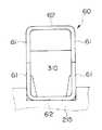
図8の実施例を説明する。対象の部材60、60はC状の断面形状となっている。部材60は、実質的に平行な2つの片61と、その一端を接続する片62とからなる。一方の形材の片61、61の他端と他方の形材60の片61、61の他端との突き合わせ部を摩擦攪拌接合する。突き合わせた形材60、60の空間には裏座310を入れている。形材60、60は突き合わせ部を横にして架台215に載っている。裏座310はクレーンで上方から入れる。架台215は下方の形材60を位置決めするように凹状になっている。摩擦攪拌接合は左右から同時にするとよい。
【0037】
本発明の技術的範囲は、特許請求範囲の各請求項に記載の文言あるいは課題を解決するための手段の項に記載の文言に限定されず、当業者がそれから容易に置き換えられる範囲にも及ぶものである。
【0038】
【発明の効果】
本発明によれば、接合時の荷重を裏座で負担できるので、形材のリブの板厚を減少でき、軽量にできるものである。
【図面の簡単な説明】
【図1】本発明の一実施例の接合部の縦断面図。
【図2】本発明の一実施例の接合装置の側面図。
【図3】対象とする中空形材の縦断面図。
【図4】鉄道車両の車体の斜視図。
【図5】本発明の他の実施例の接合装置の側面図。
【図6】本発明の他の実施例の裏座の縦断面図。
【図7】本発明の他の実施例の接合部の縦断面図。
【図8】本発明の他の実施例の接合部の縦断面図。
【符号の説明】
10,20,40,60:形材、11,12,12b,22b,21,22:面板、13,14:リブ、200,213,215:架台、210,270,290,300,310,320:裏座、293:エアーバック。[0001]
TECHNICAL FIELD OF THE INVENTION
The present invention relates to a method for friction stir welding of hollow materials. For example, it is suitable for friction stir welding of aluminum alloy hollow extruded members used for railway vehicles, aircraft, buildings and the like.
[0002]
[Prior art]
The friction stir welding method is a method in which a round bar (referred to as a rotary tool) inserted into a joint is moved along a joining line while rotating, so that the joint is heated, softened, plastically flowed, and solid-phase joined. The rotary tool has a small diameter portion inserted into the joint and a large diameter portion located outside. The small diameter part and the large diameter part are coaxial. The boundary between the small diameter portion and the large diameter portion is slightly inserted into the joint. Joining by the friction stir welding method is applied to hollow extruded members. This is disclosed in JP-A-09-309164 (EP0797043A2).
[0003]
[Problems to be solved by the invention]
At the time of friction stir welding by a rotary tool, a large load acts on a member to be welded. For this reason, when joining hollow members, a rib is provided at the joint, and the load is supported by the rib. For this reason, the weight ofthe profile increases, and the weight increase becomes a serious problem in fields aiming at weight reduction such as railway vehicles and aircraft. An object of the present invention is to reduce this weight increase.
[0004]
[Means for Solving the Problems]
The object is thatthe end of one face plate of the first section protrudes toward the adjacent section than the end of the other face plate, and the end of one face plate of the second section is A hollow profile protruding from the end of the other face plate toward the adjacent profile side, wherein the end of one face plate of the first profile and the one face plate of the second profile are formed. The first section and the second section are placed on a gantry with the ends facing each other,
The end portions of the one face plate joined together are joined by friction stir welding from the other face plate side, and then,the end of the other face plate of the first profile and the other end of the second profile are joined. A connecting member disposed between the first and second profile members; and a backing member disposed between one of the first profile member and the second profile member and the other face plate. Supports the end of the respective other face plate and the end of the connecting material with respect to the respective one face plate, and friction stir welding the end of the respective other face plate and the end of the connecting material, At the time of this friction stir welding, it can be achieved bymoving the backing to the joining position in the joining direction in synchronization with the joining speed .
[0005]
BEST MODE FOR CARRYING OUT THE INVENTION
One embodiment of the present invention will be described with reference to FIGS.
[0006]
The
[0007]
The ends of the
[0008]
The combined width of the two
[0009]
End of the face plate 11 to the end portion of the
[0010]
The butted portion of the face plate 11 and the connecting member 30 (the position where the friction stir welding is performed), that is, the corner from the face plate 11 to the
[0011]
The end of the
[0012]
At the end of the
[0013]
When joining the connecting
[0014]
The procedure of friction stir welding will be described. First, the
[0015]
Next, friction stir welding is performed from above using the space between the
[0016]
In this friction stir welding, burrs and
[0017]
Next, the
[0018]
[0019]
In order to prevent the
[0020]
When the
Next, the connecting
[0022]
Next, the
[0023]
In FIG. 2, the
[0024]
When the joining of both ends of the connecting
[0025]
Next, outside the left ends of the
[0026]
The projecting
[0027]
Another embodiment of the backing will be described with reference to FIG. The
[0028]
After the friction stir welding, the
[0029]
The embodiment of FIG. 6 will be described. The
[0030]
The method of using the
[0031]
The other is to raise the
[0032]
The embodiment of FIG. 7 will be described. Two
[0033]
Explaining the operation procedure, the
[0034]
Next, the
[0035]
Next, the
[0036]
The embodiment of FIG. 8 will be described. The
[0037]
The technical scope of the present invention is not limited to the language described in each claim of the claims or the language described in the section of the means for solving the problem, and extends to the range easily replaced by those skilled in the art. Things.
[0038]
【The invention's effect】
ADVANTAGE OF THE INVENTION According to this invention, since the load at the time of joining can be borne by a backing, the plate | board thickness of the rib of a profile can be reduced and weight can be reduced.
[Brief description of the drawings]
FIG. 1 is a longitudinal sectional view of a joint according to an embodiment of the present invention.
FIG. 2 is a side view of the joining apparatus according to one embodiment of the present invention.
FIG. 3 is a longitudinal sectional view of a hollow material to be processed.
FIG. 4 is a perspective view of a vehicle body of a railway vehicle.
FIG. 5 is a side view of a joining apparatus according to another embodiment of the present invention.
FIG. 6 is a longitudinal sectional view of a backing according to another embodiment of the present invention.
FIG. 7 is a longitudinal sectional view of a joint according to another embodiment of the present invention.
FIG. 8 is a longitudinal sectional view of a joint according to another embodiment of the present invention.
[Explanation of symbols]
10, 20, 40, 60: Profile, 11, 12, 12b, 22b, 21, 22: Face plate, 13, 14: Rib, 200, 213, 215: Stand, 210, 270, 290, 300, 310, 320 : Back seat, 293: Air bag.
Claims (1)
Translated fromJapanese実質的な平行な二枚の面板と前記二枚の面板を接続する複数のリブとからなる第2の形材とを、隣接して架台に載せて両者を接合する摩擦攪拌接合方法において、
前記第1の形材の一方の面板の端部は、他方の面板の端部よりも隣接した形材側へ突出しており、前記第2の形材の一方の面板の端部は、他方の面板の端部よりも隣接した形材側へ突出しており、
前記第1の形材の一方の面板の端部と前記第2の形材の一方の面板の端部とを突き合わせて、該第1の形材および第2の形材を架台に載せ、
付き合わせた前記一方の面板の端部同士を、他方の面板側より摩擦攪拌接合し、
次に、前記第1の形材の他方の面板の端部と、前記第2の形材の他方の面板の端部との間に接続材を配置し、
前記第1の形材および第2の形材のそれぞれの一方の面板とそれぞれ他方の面板との間に裏座を配置し、前記裏座は前記各一方の面板に対して前記各他方の面板の端部と接続材の端部を支持しており、
前記各他方の面板の端部と前記接続材の端部を摩擦攪拌接合し、この摩擦攪拌接合の際に、接合加工位置に前記裏座を接合加工速度に同期させて接合方向に移動させること、
を特徴とする摩擦攪拌接合方法。A first section formed of two substantially parallel face plates and a plurality of ribs connecting the two face plates;
In a friction stir welding method of joining two substantially parallel face plates and a second shape member composed of a plurality of ribs connecting the two face plates, and placing the two on a gantry adjacent to each other,
The end of one face plate of the first section protrudes toward the adjacent section than the end of the other face plate, and the end of one face plate of the second section is the other end. It protrudes from the end of the face plate toward the adjacent profile,
An end of one face plate of the first section and an end of one face plate of the second section are abutted, and the first section and the second section are placed on a gantry,
Friction stir welding of the end portions of the abutted one face plate from the other face plate side,
Next, a connecting member is disposed between an end of the other face plate of the first section and an end of the other face plate of the second section,
A backing plate is disposed between one face plate and the other face plate of each of the first and second profiles, and the backing seat is provided on the other face plate with respect to the one face plate. And the end of the connection material,
Friction stir welding between the end of each of the other face plates and the end of the connecting member, and in this friction stir welding, moving the back seat to the joining position in the joining direction in synchronization with the joining speed. ,
A friction stir welding method characterized by the following.
Priority Applications (6)
| Application Number | Priority Date | Filing Date | Title |
|---|---|---|---|
| JP2000042290AJP3571601B2 (en) | 2000-02-21 | 2000-02-21 | Friction stir welding method |
| TW089123015ATW460348B (en) | 2000-02-21 | 2000-11-01 | Friction stir welding method |
| EP01301464AEP1129811A3 (en) | 2000-02-21 | 2001-02-19 | friction stir welding method |
| KR1020010008515AKR20010083201A (en) | 2000-02-21 | 2001-02-20 | Friction stir welding method |
| AU23150/01AAU2315001A (en) | 2000-02-21 | 2001-02-21 | Friction stir welding method |
| US09/788,494US20010015370A1 (en) | 2000-02-21 | 2001-02-21 | Friction stir welding method |
Applications Claiming Priority (1)
| Application Number | Priority Date | Filing Date | Title |
|---|---|---|---|
| JP2000042290AJP3571601B2 (en) | 2000-02-21 | 2000-02-21 | Friction stir welding method |
Related Child Applications (2)
| Application Number | Title | Priority Date | Filing Date |
|---|---|---|---|
| JP2000055861ADivisionJP3625725B2 (en) | 2000-03-01 | 2000-03-01 | Extruded profile for friction stir welding |
| JP2000055860ADivisionJP2001232485A (en) | 2000-03-01 | 2000-03-01 | Friction stir welding method |
Publications (2)
| Publication Number | Publication Date |
|---|---|
| JP2001232484A JP2001232484A (en) | 2001-08-28 |
| JP3571601B2true JP3571601B2 (en) | 2004-09-29 |
Family
ID=18565386
Family Applications (1)
| Application Number | Title | Priority Date | Filing Date |
|---|---|---|---|
| JP2000042290AExpired - Fee RelatedJP3571601B2 (en) | 2000-02-21 | 2000-02-21 | Friction stir welding method |
Country Status (6)
| Country | Link |
|---|---|
| US (1) | US20010015370A1 (en) |
| EP (1) | EP1129811A3 (en) |
| JP (1) | JP3571601B2 (en) |
| KR (1) | KR20010083201A (en) |
| AU (1) | AU2315001A (en) |
| TW (1) | TW460348B (en) |
Families Citing this family (8)
| Publication number | Priority date | Publication date | Assignee | Title |
|---|---|---|---|---|
| JP3070735B2 (en)* | 1997-07-23 | 2000-07-31 | 株式会社日立製作所 | Friction stir welding method |
| JP3589930B2 (en)* | 2000-02-25 | 2004-11-17 | 株式会社日立製作所 | Friction stir welding method |
| JP3751215B2 (en)* | 2001-04-16 | 2006-03-01 | 株式会社日立製作所 | Friction stir welding method |
| NL1019889C2 (en)* | 2002-02-01 | 2003-08-04 | Stephanus Schinkel | Connection method for joining together construction elements, uses combination of friction stir welding and connector device |
| US6659331B2 (en)* | 2002-02-26 | 2003-12-09 | Applied Materials, Inc | Plasma-resistant, welded aluminum structures for use in semiconductor apparatus |
| FR2907040B1 (en) | 2006-10-13 | 2009-06-26 | Alstom Transport Sa | METHOD FOR ASSEMBLING A STRUCTURE COMPRISING AN EXTERIOR AND AN INTERIOR CONSISTING OF A PLURALITY OF DOUBLE-SKIN ELEMENTS, SUCH AS A RAILWAY VEHICLE CASE, AND STRUCTURE OBTAINED |
| CN104169043B (en) | 2012-02-09 | 2016-10-12 | 依赛彼公司 | Support and Backing Configurations for Friction Stir Welding |
| US11541440B2 (en) | 2019-07-25 | 2023-01-03 | National Research Council Of Canada | Snap-fit extrusions for forming panels |
Family Cites Families (4)
| Publication number | Priority date | Publication date | Assignee | Title |
|---|---|---|---|---|
| CN1165403C (en)* | 1996-03-19 | 2004-09-08 | 株式会社日立制作所 | Components for friction welding |
| JPH1147957A (en)* | 1997-07-30 | 1999-02-23 | Hitachi Ltd | Friction stir welding method |
| JPH11226757A (en)* | 1998-02-20 | 1999-08-24 | Hitachi Ltd | Friction welding method |
| JP3449403B2 (en)* | 1998-07-15 | 2003-09-22 | 日本軽金属株式会社 | Probe for penetration friction stir welding |
- 2000
- 2000-02-21JPJP2000042290Apatent/JP3571601B2/ennot_activeExpired - Fee Related
- 2000-11-01TWTW089123015Apatent/TW460348B/ennot_activeIP Right Cessation
- 2001
- 2001-02-19EPEP01301464Apatent/EP1129811A3/ennot_activeWithdrawn
- 2001-02-20KRKR1020010008515Apatent/KR20010083201A/ennot_activeCeased
- 2001-02-21AUAU23150/01Apatent/AU2315001A/ennot_activeAbandoned
- 2001-02-21USUS09/788,494patent/US20010015370A1/ennot_activeAbandoned
Also Published As
| Publication number | Publication date |
|---|---|
| AU2315001A (en) | 2001-08-23 |
| KR20010083201A (en) | 2001-08-31 |
| JP2001232484A (en) | 2001-08-28 |
| US20010015370A1 (en) | 2001-08-23 |
| TW460348B (en) | 2001-10-21 |
| EP1129811A3 (en) | 2003-05-07 |
| EP1129811A2 (en) | 2001-09-05 |
Similar Documents
| Publication | Publication Date | Title |
|---|---|---|
| AU780657B2 (en) | Friction stir welding method, and method for manufacturing car body | |
| JP4280374B2 (en) | Aircraft outer shell member and manufacturing method thereof | |
| JP3571601B2 (en) | Friction stir welding method | |
| JP2000334581A (en) | Structure and method of manufacturing the same | |
| JP2002316273A (en) | Friction stir welding method | |
| JP3242343B2 (en) | Chassis support beam and method of manufacturing the same | |
| JP3625725B2 (en) | Extruded profile for friction stir welding | |
| JP2001232485A (en) | Friction stir welding method | |
| JP3480913B2 (en) | How to make a structure | |
| JP2000094156A (en) | Friction stir welding method and friction stir welding device | |
| JP4633999B2 (en) | How to make a car body | |
| JP4417895B2 (en) | How to make a car body | |
| JP2005246483A (en) | Manufacturing method of vehicle body by friction stir welding method and vehicle body | |
| JPH11129079A (en) | Thermal processing method and thermal processing apparatus | |
| JP4291311B2 (en) | Friction stir welding method | |
| JP2020062790A (en) | Lining body, band manufacturing method | |
| AU2005200430B2 (en) | Friction stir welding method, and method for manufacturing car body | |
| JP2001150157A (en) | Shaped material for friction stir welding | |
| JP2000343247A (en) | Hollow profile | |
| JP4264186B2 (en) | Method and apparatus for butt joining steel plates or steel strips | |
| JP2002059278A (en) | Friction stir welding method | |
| ATE473831T1 (en) | CAR BODY STRUCTURE OF A RAIL VEHICLE AND CONNECTION STRUCTURE FOR FRICTION WELDING | |
| JPH10128850A (en) | Sheet heating welder | |
| JP2005342790A (en) | Friction stir welding method | |
| JP2002316274A (en) | Hollow profile for friction stir welding |
Legal Events
| Date | Code | Title | Description |
|---|---|---|---|
| A131 | Notification of reasons for refusal | Free format text:JAPANESE INTERMEDIATE CODE: A131 Effective date:20040323 | |
| A25B | Request for examination refused [due to the absence of examination request for another application deemed to be identical] | Free format text:JAPANESE INTERMEDIATE CODE: A2522 Effective date:20040323 | |
| A521 | Request for written amendment filed | Free format text:JAPANESE INTERMEDIATE CODE: A523 Effective date:20040524 | |
| TRDD | Decision of grant or rejection written | ||
| A01 | Written decision to grant a patent or to grant a registration (utility model) | Free format text:JAPANESE INTERMEDIATE CODE: A01 Effective date:20040622 | |
| A61 | First payment of annual fees (during grant procedure) | Free format text:JAPANESE INTERMEDIATE CODE: A61 Effective date:20040624 | |
| R150 | Certificate of patent or registration of utility model | Free format text:JAPANESE INTERMEDIATE CODE: R150 | |
| S111 | Request for change of ownership or part of ownership | Free format text:JAPANESE INTERMEDIATE CODE: R313115 | |
| S531 | Written request for registration of change of domicile | Free format text:JAPANESE INTERMEDIATE CODE: R313531 | |
| R350 | Written notification of registration of transfer | Free format text:JAPANESE INTERMEDIATE CODE: R350 | |
| S531 | Written request for registration of change of domicile | Free format text:JAPANESE INTERMEDIATE CODE: R313531 | |
| S533 | Written request for registration of change of name | Free format text:JAPANESE INTERMEDIATE CODE: R313533 | |
| R350 | Written notification of registration of transfer | Free format text:JAPANESE INTERMEDIATE CODE: R350 | |
| FPAY | Renewal fee payment (event date is renewal date of database) | Free format text:PAYMENT UNTIL: 20080702 Year of fee payment:4 | |
| FPAY | Renewal fee payment (event date is renewal date of database) | Free format text:PAYMENT UNTIL: 20090702 Year of fee payment:5 | |
| LAPS | Cancellation because of no payment of annual fees |