JP3571414B2 - Ultrasonic incision coagulation equipment - Google Patents
Ultrasonic incision coagulation equipmentDownload PDFInfo
- Publication number
- JP3571414B2 JP3571414B2JP11341095AJP11341095AJP3571414B2JP 3571414 B2JP3571414 B2JP 3571414B2JP 11341095 AJP11341095 AJP 11341095AJP 11341095 AJP11341095 AJP 11341095AJP 3571414 B2JP3571414 B2JP 3571414B2
- Authority
- JP
- Japan
- Prior art keywords
- probe
- ultrasonic
- gripping member
- treatment
- living tissue
- Prior art date
- Legal status (The legal status is an assumption and is not a legal conclusion. Google has not performed a legal analysis and makes no representation as to the accuracy of the status listed.)
- Expired - Lifetime
Links
- 230000015271coagulationEffects0.000titleclaimsdescription56
- 238000005345coagulationMethods0.000titleclaimsdescription56
- 239000000523sampleSubstances0.000claimsdescription121
- 238000011282treatmentMethods0.000claimsdescription76
- 230000005540biological transmissionEffects0.000claimsdescription19
- 238000003780insertionMethods0.000description22
- 230000037431insertionEffects0.000description22
- 238000010586diagramMethods0.000description10
- 238000010292electrical insulationMethods0.000description5
- 230000000694effectsEffects0.000description4
- 230000002439hemostatic effectEffects0.000description4
- 239000011347resinSubstances0.000description4
- 229920005989resinPolymers0.000description4
- 239000000919ceramicSubstances0.000description3
- 239000011248coating agentSubstances0.000description3
- 238000000576coating methodMethods0.000description3
- 238000002674endoscopic surgeryMethods0.000description3
- 230000023597hemostasisEffects0.000description3
- 238000012856packingMethods0.000description3
- 239000004810polytetrafluoroethyleneSubstances0.000description3
- 229920001343polytetrafluoroethylenePolymers0.000description3
- 239000004696Poly ether ether ketoneSubstances0.000description2
- 238000004140cleaningMethods0.000description2
- 230000001112coagulating effectEffects0.000description2
- 238000000034methodMethods0.000description2
- 229920002492poly(sulfone)Polymers0.000description2
- 238000002271resectionMethods0.000description2
- 230000001954sterilising effectEffects0.000description2
- PNEYBMLMFCGWSK-UHFFFAOYSA-NAluminaChemical compound[O-2].[O-2].[O-2].[Al+3].[Al+3]PNEYBMLMFCGWSK-UHFFFAOYSA-N0.000description1
- 230000000740bleeding effectEffects0.000description1
- 230000007850degenerationEffects0.000description1
- 239000012777electrically insulating materialSubstances0.000description1
- 238000012277endoscopic treatmentMethods0.000description1
- 238000002350laparotomyMethods0.000description1
- 239000000463materialSubstances0.000description1
- 238000003825pressingMethods0.000description1
- 238000004659sterilization and disinfectionMethods0.000description1
- 230000001225therapeutic effectEffects0.000description1
- 210000001835visceraAnatomy0.000description1
Images


Classifications
- A—HUMAN NECESSITIES
- A61—MEDICAL OR VETERINARY SCIENCE; HYGIENE
- A61B—DIAGNOSIS; SURGERY; IDENTIFICATION
- A61B17/00—Surgical instruments, devices or methods
- A61B17/32—Surgical cutting instruments
- A61B17/320068—Surgical cutting instruments using mechanical vibrations, e.g. ultrasonic
- A61B17/320092—Surgical cutting instruments using mechanical vibrations, e.g. ultrasonic with additional movable means for clamping or cutting tissue, e.g. with a pivoting jaw
- A61B2017/320094—Surgical cutting instruments using mechanical vibrations, e.g. ultrasonic with additional movable means for clamping or cutting tissue, e.g. with a pivoting jaw additional movable means performing clamping operation
- A—HUMAN NECESSITIES
- A61—MEDICAL OR VETERINARY SCIENCE; HYGIENE
- A61B—DIAGNOSIS; SURGERY; IDENTIFICATION
- A61B17/00—Surgical instruments, devices or methods
- A61B17/32—Surgical cutting instruments
- A61B17/320068—Surgical cutting instruments using mechanical vibrations, e.g. ultrasonic
- A61B17/320092—Surgical cutting instruments using mechanical vibrations, e.g. ultrasonic with additional movable means for clamping or cutting tissue, e.g. with a pivoting jaw
- A61B2017/320095—Surgical cutting instruments using mechanical vibrations, e.g. ultrasonic with additional movable means for clamping or cutting tissue, e.g. with a pivoting jaw with sealing or cauterizing means
Landscapes
- Health & Medical Sciences (AREA)
- Surgery (AREA)
- Engineering & Computer Science (AREA)
- Life Sciences & Earth Sciences (AREA)
- Heart & Thoracic Surgery (AREA)
- Nuclear Medicine, Radiotherapy & Molecular Imaging (AREA)
- Mechanical Engineering (AREA)
- Biomedical Technology (AREA)
- Dentistry (AREA)
- Medical Informatics (AREA)
- Molecular Biology (AREA)
- Animal Behavior & Ethology (AREA)
- General Health & Medical Sciences (AREA)
- Public Health (AREA)
- Veterinary Medicine (AREA)
- Surgical Instruments (AREA)
Description
Translated fromJapanese【0001】
【産業上の利用分野】
本発明は、超音波振動によって生体組織の切除あるいは凝固する処置に加え、高周波電流による処置を行える超音波切開凝固装置に関する。
【0002】
【従来技術】
近年、体腔内に細長の挿入部を挿入することにより、体腔内臓器などを観察したり、必要に応じて内視鏡観察下で各種治療処置が行われている。
【0003】
前記内視鏡観察下で治療処置を行う方法の一つとして生体組織を吸着あるいは把持し、この吸着あるいは把持している部材に超音波振動を加えて生体組織を切除あるいは凝固するなどの処置を行うものが知られている。
【0004】
例えば、特開昭62−127042号公報には結石を把持して超音波振動により破砕するようにした超音波砕石プローブが示されている。また、特開平1−232944号公報には生体組織を把持鉗子で把持固定し、超音波振動するプローブで切開するようにした外科用手術装置が示されている。さらに、特開平1−232945号公報には生体組織を吸着して固定し、超音波振動するメスにより切開するようにした外科用手術装置が示されている。又、特開平1−232948号公報には切除鉗子に超音波振動を加えることにより生体組織の切除を効率的に行えるようにした外科用切除鉗子が示されている。また更に、特開平1−232949号公報には前記特開平1−232944号公報と同様に把持手段により生体組織を固定し、超音波振動を加えた可動部材により生体組織に処置を加えるようした外科用手術装置が示されている。又、USP5322055号には超音波プローブに向かって回動自在な把持部材を設け、この超音波プローブと把持部材とで生体組織を把持して超音波振動を付加することによって生体組織を凝固したり切開したりできるようにした超音波外科器具のためのクランプ凝固装置及び切断システムが示されている。これら超音波を用いて処置を行う装置では通常の外科鉗子を使用するように生体組織を把持して処置が行えるので、プローブ単体で処置を行う場合よりも良好な処置を行うことができる。
【0005】
一方、高周波電流による処置が行えるものとしては特開平6−179049号公報に示すような内視鏡外科手術用処置具が一般的であり、その殆どがモノポーラと呼ばれる高周波電流を処置具から生体組織を通して体極板と呼ばれる帰還部に流して処置を行うタイプであった。このタイプの処置具は止血性能が優れていた。
【0006】
これに対して特開平6−30947号公報に示されているバイポーラと呼ばれる処置具は、鉗子部の把持部材間に高周波電流の回路を組み込んだタイプであった。このタイプの処置具は、生体組織の不要な部分には高周波電流が流れないようになっており、鉗子部材を電気的に絶縁し、鉗子部材を駆動する伝達部材とシースとを絶縁する一方でそれぞれに給電手段が設けられていた。
【0007】
【発明が解決しようとする課題】
しかしながら、上述の特開昭62−127042号公報,特開平1−232944号公報や特開平1−232948号公報などに示されている超音波を用いて処置を行う装置では生体組織に対して超音波振動による処置しか行うことができなかった。一般に、超音波振動による処置は、高周波電流による処置に比べて止血能力が劣るため、緊急に止血したい場合などには超音波振動を用いる処置具から高周波電流を用いる処置具に交換しなければならず、使い勝手が悪かった。
【0008】
一方、高周波電流による処置が行える特開平6−179049号公報の内視鏡外科手術用処置具では生体組織の不要な部分に電流が流れるおそれがあるという問題の他に、上述の高周波電流を用いて処置を行う内視鏡用処置具では高周波電流による処置しか行うことができず、止血性能は良好であるが、生体組織に及ぼす影響が大きく、過度の焼灼を行うおそれがあった。
【0009】
このため、実際に処置を行う術者にとっては、超音波振動による処置をできるだけ行い、必要な時にだけ高周波電流による処置を行えることが理想的であるが、内視鏡外科手術用処置具単体で超音波振動による処置を行い、必要な時だけ高周波電流による処置を行うことは不可能であった。
【0010】
そこで、これらの問題を解決するため、特開平3−111037号公報や、特開平5−23348号公報及びUSP4931047号には超音波振動と高周波電流による処置を併用できる超音波吸引器などと呼ばれる超音波処置装置が示されている。これらの装置では、棒状あるいはヘラ状に形成したプローブを生体組織に押し付けて処置するようになっていた。このため、前記プローブを確実に目的の生体組織を押さえて処置を行うことが難しく、細かい操作を行うためには他に複数の鉗子等で補助する必要があった。しかし、通常の開腹手術では問題とはならない操作でも、内視鏡下外科手術においては、複数の内視鏡下外科手術用処置具である鉗子を用いることは生体組織に多数の孔を開けることになるので、低侵襲という点で問題があった。さらに、モニターの画面上に表示される内視鏡画像を観察しながら遠隔操作を行って、複数の処置具と協調操作することが難かしく、簡単で、且つ、確実に処置のできる処置具が望まれていた。なお、前記USP5322055号のクランプ凝固装置及び切断システムはこの問題を解決するものであるが、前述したように高周波電流を用いる処置を併用することができないという問題があった。
【0011】
本発明は上記事情に鑑みてなされたものであり、凝固、切開及び止血の各処置に応じて処置具を交換することなく、一つの装置により、所望の生体組織に対して凝固あるいは切開の処置に加えて、止血能力の高い高周波電流による処置を行う超音波切開凝固装置を提供することを目的とする。
【0012】
【課題を解決するための手段】
請求項1に係る超音波切開凝固装置は、超音波振動を発生する超音波振動子と、
長手軸が定義され、前記長手軸により特定される先端部を有し、導電性を備え、前記超音波振動子で発生した超音波振動に応じた所定の振動を前記先端部に伝達可能に前記超音波振動子と結合する軸方向に延在したプローブと、導電性を備え、前記プローブの先端部の延出する方向に沿って前記プローブの先端部に形成されるプローブ表面との間で生体組織を把持して該生体組織を切開あるいは凝固するために前記プローブ表面に対して開閉動作可能に配置される把持部材と、前記把持部材の開閉動作を操作するための操作手段と、導電性を備え、前記把持部材に前記操作手段の操作量に応じた開閉動作が生じるように前記操作量を伝達する伝達手段と、前記生体組織に高周波電流による処置を施すために前記プローブ及び前記把持部材と電気的に結合される高周波電源と、を備えることを特徴とする。
また、請求項2に係る超音波切開凝固装置は、超音波振動を発生する超音波振動子と、長手軸が定義され、前記長手軸により特定される先端部を有し、前記超音波振動子で発生した超音波振動に応じた所定の振動を前記先端部に伝達可能に前記超音波振動子と結合する軸方向に延在したプローブと、導電性を備え、前記プローブの先端部の延出する方向に沿って前記プローブの先端部に形成されるプローブ表面との間で生体組織を把持して該生体組織を切開あるいは凝固するために前記プローブ表面に対して開閉動作可能に配置される把持部材と、前記把持部材の開閉動作を操作するための操作手段と、導電性を備え、前記把持部材に前記操作手段の操作量に応じた開閉動作が生じるように前記操作量を伝達する伝達手段と、前記生体組織に高周波電流による処置を施すために前記把持部材と電気的に結合される高周波電源と、を備えることを特徴とする。
【0013】
この構成によれば、プローブ先端部と把持部材との間で生体組織を把持し、超音波振動子からの振動に基づいて生体組織を凝固あるいは切開する処置を施すことができ、また、生体組織に対して高周波電流による処置を施すことが可能になる。
【0014】
【実施例】
以下、図面を参照して本発明の実施例を説明する。
図1ないし図6は本発明の一実施例に係り、図1は超音波切開凝固装置の概略構成を示す図、図2は超音波切開凝固装置の挿入部先端側を説明する断面図、図3は図2のA―A断面図、図4は図2のB―B断面図、図5は超音波切開凝固装置の挿入部手元側と操作部とを説明する断面図、図6は超音波切開凝固装置の回路構成を説明する模式図である。
【0015】
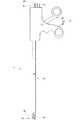
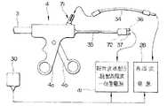
図1に示すように超音波切開凝固装置1は、処置部2と、この処置部2を体腔内に挿入する後述する管路を備えた挿入部3と、前記処置部2を操作する固定操作ハンドル4a及び可動操作ハンドル4bを有する操作部4などを備えている。前記処置部2は、挿入部3の先端部に位置しており、挿入部3の先端面から突出するプローブ5と把持部材6とで構成されている。なお、前記処置部2を構成するプローブ5に超音波振動を供給する後述する超音波振動子は操作部内に内蔵されている。符号7は第1の高周波電流用コードであり、符号8は第2の高周波電流用コード,そして、符号9は超音波振動子駆動用コードである。
【0016】
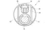
図2に示すように挿入部3の先端側に位置する処置部2は、挿入部3の先端面から突出するプローブ5と、このプローブ5に対向して配設された把持部材6とで構成されている。この把持部材6は、前記操作部4の可動操作ハンドル4bを術者が操作することによって、この可動操作ハンドル4bと把持部材6とを接続している伝達部材10が長手方向に進退して、前記把持部材6をプローブ5に対して開閉動作するようになっている。
【0017】
前記挿入部3は、電気絶縁性を有する例えば、ポリサルフォンやPEEK等の樹脂部材で形成された電気絶縁手段となるシース11であり、このシース11には前記プローブ5が挿通するプローブ挿通用管路12と、前記把持部材6に接続する伝達部材10が挿通する伝達部材用管路13とが電気的に完全に絶縁されて設けられている。
【0018】
図2及び図3に示すように前記伝達部材用管路13の先端側開口部には電気絶縁性を有する先端カバー14が嵌入固定されており、前記シース11と同様にポリサルフォンやPEEK等の樹脂材料あるいはセラミックなどで形成されている。この先端カバー14には前記把持部材6が第1のピン21によって回動自在に取り付けられている。
【0019】
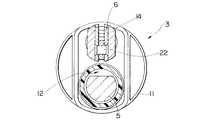
また、図2及び図4に示すように前記把持部材6に可動操作ハンドル4bの操作力を伝達する伝達部材10とはに第2のピン22で回動及び摺動自在に固定されており、伝達部材10の進退動作に対応して前記第1のピン21を中心にして把持部材6がプローブ5に対して回動動作するようになっている。
【0020】
そして、図2ないし図4に示すように前記プローブ挿通用管路12の先端側開口部にはプローブ5がシース11に接触して超音波振動することによってシース11が損傷することを防止するための保護部材15が配設されている。この保護部材15は、超音波振動に対する耐性を有すると共に、耐熱性に優れ、且つ電気絶縁性を有する例えばセラミックやPTFE等の部材で形成されている。
【0021】
なお、前記把持部材6のプローブ5に対向する面以外の露出する面部及び先端カバー14のシース11から露出する部分には高周波電流が漏れることを防止する例えばPTFE等の絶縁塗装やアルミナセラミック等の電気絶縁性を有するセラミックがCVDコーティングされている。
【0022】
また、前記把持部材6と同様、プローブ5に対しても前記把持部材6が対向する面以外の先端側部を除く露出している面部にCVDコーティングを施すことによって高周波電流の生体組織への漏れをより一層防止して安全性が増大する。
【0023】
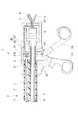
図5に示すように操作部4は、挿入部3の手元側端部に設けられており、この操作部4の内部には超音波振動子16が設けられている。また、操作部4の先端側に位置する固定ハンドル4aの上方部には挿入部3が接続固定されている。前記固定ハンドル4aには可動ハンドル4bが第3のピン23で回動自在に軸支されており、この可動ハンドル4bの回動動作が伝達部材10に伝達されるようになっている。なお、前記固定ハンドル4a及び可動ハンドル4bは共にポリサルフォンやBEEK等の電気絶縁性のある材質で形成されている。
【0024】
前記伝達部材10の手元側端部には球状部24aを形成した係合部材24が固定されている。この球状部24aは、可動ハンドル4bの上方部に形成されている係合溝24に回動摺動自在に保持されている。この係合溝24には球状部24aに接触するように導電部材25が設けられており、この導電部材25に高周波電源からの高周波電流を把持部材6に給電するための第1高周波電流コード7が接続されている。また、前記超音波振動子16の後部からは前記プローブ5に高周波電流を給電するための第2高周波電流コード8及び超音波振動子16に駆動用電流を給電するための超音波振動子駆動用コード9が接続されている。
【0025】
なお、前記挿入部3を構成するシース11の伝達部材用管路13の端部が位置する開口部には第1のパッキン31aが設けられており、伝達部材用管路13から気腹ガスなどが漏れるのを防止している。
【0026】
また、前記プローブ挿通用管路12の手元側端部には超音波振動に対する耐性を有すると共に、耐熱性に優れ、且つ電気絶縁性を有するPTFE等の樹脂部材で形成した電気絶縁手段となるチューブ26が、前記可動ハンドル4bの内部を貫通して超音波振動子ハウジング27まで設けてある。このため、前記プローブ5は、プローブ挿通用管路12から超音波振動子ハウジング27までの間で完全に他部材から隔離している。
【0027】
さらに、前記超音波振動子ハウジング27の後方部は第2のパッキン32によって密閉され、前記第1高周波電流コード7の前方出口も第3のパッキン33によって密閉されている。
【0028】
すなわち、超音波切開凝固装置1は、前記プローブ5及び超音波振動子16と、係合部材24,伝達部材10,先端カバー14及び把持部材6とがお互いに電気的に完全に絶縁されると共に、前記プローブ5及び超音波振動子16と、係合部材24,伝達部材10,先端カバー14及び把持部材6とは外部に対しても電気的に絶縁されている。
【0029】
図6に示すように超音波切開凝固装置1において、処置部2を構成する把持部材6は、伝達部材10、係合部材24、導電部材25、第1高周波電流コード7、把持部材用高周波電流コネクタ7aを経て高周波電源28に接続されている。一方、処置部2を構成するプローブ5は、超音波振動子16、第2高周波電流コード8、プローブ用高周波電流コネクタ8aを経て高周波電源28に接続されている。さらに、超音波振動子16は、超音波振動子駆動用コード9、超音波振動子駆動用コネクタ9aを経て超音波振動子駆動電源29に接続されている。
【0030】
又、体極板30が高周波電源28の帰還部側に接続されている。このように把持部材6とプローブ5とは電気的に完全に絶縁されている。
【0031】
上述のように構成されている超音波切開凝固装置1の作用を説明する。
まず、超音波切開凝固装置1を生体内の目的の生体組織に対向させる。そして、操作部4の可動ハンドル4bを開状態になるように操作して把持部材6をプローブ5に対して開放させる。
【0032】
次に、目的の生体組織を把持部材6とプローブ5と間に挟みこむために前記可動ハンドル4bを閉状態になるように操作して把持部材6をプローブ5に対して閉鎖させることによって生体組織を把持する。
【0033】
次いで、この状態で、超音波振動子駆動電源29から超音波振動子駆動用電流を超音波振動子16に給電して超音波振動子16を駆動する。すると、超音波振動子16が振動することによってプローブ5に超音波振動が伝達され、この超音波振動を生体組織に与えて、生体組織の切開あるいは凝固を行う。
【0034】
一方、高周波電流を用いる処置を行う場合は、把持部材6とプローブ5との間に生体組織を把持して把持部材6あるいはプローブ5のどちらかまたは把持部材6及びプローブ5の両方に高周波電源28から高周波電流を給電する。このとき、把持部材6、プローブ5から体極板30へ図6の破線に示すように生体組織を通して高周波電流を流し、高周波電源28に帰還させることにより、生体組織の切開あるいは凝固を行う。
【0035】
なお、生体組織を把持部材6とプローブ5との間に把持せずにプローブ5を生体組織に押し付けて超音波振動を与えて処置を行うようにしても良い。また、体極板30を使用することなく、生体組織を把持部材6とプローブ5とによって把持し、前記把持部材6とプローブ5との間に高周波電流を流して処置を行うようにしても良い。さらに、生体組織を把持せずに把持部材6とプローブ5とで剥離する様にしても良いし、どちらかを押し当てて処置を行うようにしても良い。
【0036】
このように、把持部材とプローブとが電気的に完全に絶縁されているので、高周波電流による処置を行う際、高周波電流の漏れがなく、処置を安全に行うことができる。
【0037】
また、超音波振動による処置と高周波電流による処置を同時に行うことが可能であるので、超音波振動による処置をできるだけ行い、必要な時にだけ高周波電流による処置を行って、良好な止血性能と、過度の組織変性防止の双方の効果を得ることができる。
【0038】
さらに、高周波電流を流して処置を行う場合、体極板を使用して生体組織に高周波電流を通して処置を行ったり、体極板を使用せずに生体組織を把持部材とプローブとの間に把持して把持部材とプローブとの間の生体組織に高周波電流を通して処置するなど術者の選択の幅が広がる。
【0039】
図7は超音波切開凝固装置と電源との関係を説明する図である。
図に示すように本実施例においては把持部材6に高周波電流を給電するための把持部材用高周波電流コネクタ71を、操作部4の上部に設けている。そして、この把持部材用高周波電流コネクタ71と高周波電源28とを高周波電流給電用コード34で接続するようになっている。一方、プローブ5に高周波電流を給電し、超音波振動子16に超音波振動子駆動用の電流を給電するための、プローブ用高周波電流・超音波振動子駆動用コネクタ72がプローブ用高周波電流・超音波振動子駆動用コード35に設けられている。前記プローブ用高周波電流・超音波振動子駆動用コネクタ72の内部にはプローブ給電用端子36と超音波振動子給電用端子37とがそれぞれ独立して設けられており、それぞれプローブ5、超音波振動子16に接続されている。そして、このプローブ用高周波電流・超音波振動子駆動用コネクタ72を備えたプローブ用高周波電流・超音波振動子駆動用コード35を、プローブ用の高周波電源を内蔵した超音波振動子駆動、高周波一体型電源41に接続して使用する。このことにより、プローブへの給電と超音波振動子への給電の接続が一度にでき、把持部材とプローブ及び超音波振動子とを分離して取り扱えるので修理等の際に便利であるという利点がある。また、把持部材に高周波電流を給電する際には高周波電源を用いることができる。
【0040】
図8は超音波切開凝固装置と電源との他の関係を説明する図である。
図に示すように本実施例においては把持部材6とプローブ5とに高周波電流を給電するための把持部材・プローブ用高周波電流コネクタ73が把持部材・プローブ用高周波コード38に設けられている。この把持部材・プローブ用高周波電流コネクタ73の内部には把持部材給電用端子39とプローブ給電用端子40がそれぞれ独立して設けられており、それぞれ把持部材6とプローブ5に接続されている。そして、この把持部材・プローブ用高周波電流コネクタ73を備えた把持部材・プローブ用高周波コード38を高周波電源28に接続して使用する。
【0041】
このことにより、高周波電流の接続を一度に行うことができると共に、高周波電源と超音波振動子駆動電源とを分離して取り扱える。
【0042】
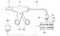
図9は超音波切開凝固装置と電源との別の関係を説明する図である。
図に示すように本実施例においては把持部材6とプローブ5とに高周波電流を給電し、超音波振動子16に超音波振動子駆動電流を給電するための把持部材・プローブ用高周波電流・超音波振動子駆動用コネクタ74が把持部材・プローブ・超音波振動子コード42に設けられている。この把持部材・プローブ用高周波電流・超音波振動子駆動用コネクタ74の内部には把持部材給電用端子43とプローブ給電用端子44と超音波振動子給電用端子45とがそれぞれ独立して設けられており、それぞれ把持部材6、プローブ5、超音波振動子16に接続されている。そして、この把持部材・プローブ用高周波電流・超音波振動子駆動用コネクタ74を備えた把持部材・プローブ・超音波振動子コード42を把持部材・プローブ用高周波電源を備えた超音波振動子駆動高周波一体型電源46に接続して使用する。このことにより、全ての接続を一度に行うことができると共に、全ての電源を一体化することができる。
【0043】
図10は超音波切開凝固装置と電源とのまた別の関係を説明する図である。
図に示すように本実施例においては把持部材・プローブ用高周波電流・超音波振動子駆動用コネクタ74を有する把持部材・プローブ・超音波振動子コード47が操作部4に対して着脱自在になっている。このため、操作部4に把持部材・プローブ用高周波電流・超音波振動子駆動用操作部側コネクタ75を設け、前記把持部材・プローブ・超音波振動子コード47に前記把持部材・プローブ用高周波電流・超音波振動子駆動用操作部側コネクタ75に着脱自在な把持部材・プローブ用高周波電流・超音波振動子駆動用コード側コネクタ76を設けている。そして、この把持部材・プローブ・超音波振動子コードを超音波振動子駆動高周波一体電源48に接続して使用する。このことにより、超音波切開凝固装置とコードとを分離できるので、断線等のトラブルの起き易いコード類の交換が容易になる。また、洗浄・滅菌の際にコードを分離して作業ができるので作業性が向上する。さらに、長さの異なるコードを使用することも可能になるうえに、断線等のトラブルの発生し易いコードを容易に交換することができる。
【0044】
[付記]
1.生体組織に超音波振動子からの超音波振動を与えるプローブ及びこのプローブに対向して回動自在な把持部材で構成した処置部と、この処置部を生体内に挿入する挿入部と、前記処置部の把持部材をプローブに対して開閉操作する操作部と、この操作部の操作力を前記把持部材に伝達する伝達部材とを備えた超音波切開凝固装置において、
前記伝達部材と前記プローブとを互いに電気的に絶縁すると共に、前記伝達部材及びプローブをそれぞれ外部に対して電気的に絶縁する電気絶縁手段を具備したことを特徴とする超音波切開凝固装置。
【0045】
2.前記プローブに超音波振動を供給する超音波振動子が、前記操作部内に配置されている付記1記載の超音波切開凝固装置。
【0046】
3.前記伝達部材が前記挿入部内を挿通している付記1記載の超音波切開凝固装置。
【0047】
4.前記伝達部材が挿通する管路と、前記プローブが挿通する管路とを電気的に絶縁した付記1記載の超音波切開凝固装置。
【0048】
このことにより、挿入部内で伝達部材及び把持部材とプローブとが挿通する4つの管路が独立し、それぞれの管路が電気的に絶縁されているので、特にプローブ外周面や伝達部材等に、絶縁塗装等の処置を施すことなく伝達部材とプローブを確実に絶縁できる。
【0049】
5.前記把持部材に高周波電流を給電する高周波電源を接続するための把持部材給電手段を設けた付記1及び付記4記載の超音波切開凝固装置。
【0050】
このことにより、超音波切開凝固装置に高周波電源を接続したり分離することが容易にできるので、超音波切開凝固装置を洗浄・滅菌する際や、交換する際の作業が容易になる。
【0051】
6.前記プローブに高周波電流を給電する高周波電源を接続するためのプローブ給電手段を設けた付記1ないし付記5記載の超音波切開凝固装置。
【0052】
7.前記把持部材給電手段が操作部に設けられているコネクタである付記5記載の超音波切開凝固装置。
【0053】
8.前記プローブ給電手段が操作部に設けられているコネクタである付記6記載の超音波切開凝固装置。
【0054】
9.前記コネクタを前記操作部から遊離させる略コード状部材を有する付記7及び付記8記載の超音波切開凝固装置。
【0055】
10.前記把持部材と前記プローブとにそれぞれに給電するためのコネクタを一体にした一体化コネクタを設けた付記7及び付記8記載の超音波切開凝固装置。
11.前記一体化コネクタ内に前記把持部材と前記プローブそれぞれに給電するための端子を別々に配置した付記10記載の超音波切開凝固装置。
【0056】
このことにより、高周波電源に接続する際、一度に接続が行える。
【0057】
12.超音波振動子と、この超音波振動子に駆動用電流を給電する超音波駆動用電源とを接続する超音波振動子給電手段を有し、この超音波振動子給電手段が操作部に設けられているコネクタである付記7ないし付記11記載の超音波切開凝固装置。
【0058】
13.前記コネクタを前記超音波切開凝固装置から遊離する略コード状部材を有する付記12記載の超音波切開凝固装置。
【0059】
14.前記超音波振動子と前記プローブとにそれぞれに給電するための前記コネクタを一体化する一方、前記超音波振動子と前記プローブとにそれぞれ給電するための端子を前記コネクタ内に別個に配置した付記12及び付記13記載の超音波切開凝固装置。
【0060】
このことにより、超音波振動子駆動用電源にプローブ用高周波電源が内蔵されているものを使用した場合、接続が一度に行えるという効果がある。
【0061】
15.前記超音波振動子と前記プローブと前記把持部材とにそれぞれに給電するためのコネクタを一体化し、前記超音波振動子と前記プローブと前記把持部材のそれぞれに給電するための端子を前記コネクタ内に別個に配置した付記14記載の超音波切開凝固装置。
【0062】
このことにより、超音波振動子駆動用電源にプローブと把持部材用の高周波電源が内蔵されているものを使用した場合、接続が一度に行える。
【0063】
【発明の効果】
以上説明したように本発明によれば、凝固、切開及び止血の各処置に応じて処置具を交換することなく、一つの装置により、所望の生体組織に対して凝固あるいは切開の処置に加えて、止血能力の高い高周波電流による処置を行うことができる超音波切開凝固装置を提供することができる。
【図面の簡単な説明】
【図1】図1ないし図6は本発明の一実施例に係り、図1は超音波切開凝固装置の概略構成を示す図
【図2】超音波切開凝固装置の挿入部先端側を説明する断面図
【図3】図2のA―A断面図
【図4】図2のB―B断面図
【図5】超音波切開凝固装置の挿入部手元側と操作部とを説明する断面図
【図6】超音波切開凝固装置の回路構成を説明する模式図
【図7】超音波切開凝固装置と電源との関係を説明する図
【図8】超音波切開凝固装置と電源との他の関係を説明する図
【図9】超音波切開凝固装置と電源との別の関係を説明する図
【図10】超音波切開凝固装置と電源とのまた別の関係を説明する図
【符号の説明】
1…超音波切開凝固装置
2…処置部
3…挿入部
6…把持部
10…伝達部材
11…シース(電気絶縁手段)[0001]
[Industrial applications]
The present invention relates to an ultrasonic incision coagulation apparatus capable of performing a treatment using a high-frequency current in addition to a treatment of removing or coagulating a living tissue by ultrasonic vibration.
[0002]
[Prior art]
2. Description of the Related Art In recent years, by inserting an elongated insertion portion into a body cavity, an internal organ or the like is observed, and various treatments are performed under endoscopic observation as needed.
[0003]
As one of the methods for performing a therapeutic treatment under the endoscope observation, a treatment of sucking or grasping a living tissue and applying ultrasonic vibration to the sucked or gripped member to cut or coagulate the living tissue is performed. What you do is known.
[0004]
For example, Japanese Patent Application Laid-Open No. Sho 62-127042 discloses an ultrasonic lithotripter in which a calculus is gripped and crushed by ultrasonic vibration. Japanese Patent Application Laid-Open No. 1-223944 discloses a surgical operation apparatus in which a living tissue is grasped and fixed by grasping forceps and incised by an ultrasonically vibrating probe. Further, Japanese Patent Application Laid-Open No. 1-223245 discloses a surgical operating apparatus in which a living tissue is adsorbed and fixed, and the incision is made with a scalpel that vibrates ultrasonically. Further, Japanese Patent Application Laid-Open No. 1-223248 discloses a surgical resection forceps in which living tissue can be efficiently resected by applying ultrasonic vibration to the resection forceps. Further, Japanese Patent Application Laid-Open No. 1-223949 discloses a surgical method in which a living tissue is fixed by a gripping means and a treatment is applied to the living tissue by a movable member to which ultrasonic vibration is applied, as in the above-mentioned Japanese Patent Application Laid-Open No. 1-223244. A surgical device is shown. In US Pat. No. 5,322,055, a gripping member is provided which is rotatable toward an ultrasonic probe. The ultrasonic probe and the gripping member grip living tissue and apply ultrasonic vibration to coagulate the living tissue. A clamp coagulation device and cutting system for an ultrasonic surgical instrument capable of being dissected is shown. In these devices for performing treatment using ultrasonic waves, the treatment can be performed while grasping the living tissue as in the case of using ordinary surgical forceps, so that a better treatment can be performed than in the case where the treatment is performed with a single probe.
[0005]
On the other hand, a treatment instrument for endoscopic surgery as disclosed in Japanese Patent Application Laid-Open No. H6-179049 is generally used as a treatment device capable of performing treatment using a high-frequency current. Through the return section called the body electrode to perform treatment. This type of treatment tool had excellent hemostatic performance.
[0006]
On the other hand, a treatment tool called bipolar disclosed in Japanese Patent Application Laid-Open No. 6-30947 is a type in which a high-frequency current circuit is incorporated between gripping members of a forceps portion. This type of treatment instrument is configured such that high-frequency current does not flow to unnecessary portions of the living tissue, electrically insulates the forceps member, and insulates the transmission member that drives the forceps member from the sheath. Each was provided with a power supply means.
[0007]
[Problems to be solved by the invention]
However, in the above-described apparatuses for performing treatment using ultrasonic waves disclosed in JP-A-62-127042, JP-A-1-232944, JP-A-1-232948, and the like, an ultra-fine treatment is performed on a living tissue. Only treatment by sonic vibration could be performed. In general, treatment by ultrasonic vibration is inferior to hemostatic treatment by high-frequency current.Therefore, when urgently necessary to stop bleeding, the treatment device using ultrasonic vibration must be replaced with a treatment device using high-frequency current. It was not easy to use.
[0008]
On the other hand, the treatment tool for endoscopic surgery disclosed in Japanese Patent Application Laid-Open No. H6-179049, which can perform a treatment using a high-frequency current, has a problem that a current may flow to an unnecessary portion of a living tissue. An endoscopic treatment tool that performs a treatment only with high-frequency current can perform treatment with high frequency current, and has good hemostasis performance, but has a large effect on living tissue, and may cause excessive cauterization.
[0009]
For this reason, it is ideal for the operator who actually performs the treatment to perform the treatment by the ultrasonic vibration as much as possible and to perform the treatment by the high-frequency current only when necessary. It was impossible to perform treatment by ultrasonic vibration and to perform treatment by high-frequency current only when necessary.
[0010]
In order to solve these problems, Japanese Patent Application Laid-Open Nos. Hei 3-111037, Hei 5-23348 and US Pat. No. 4,931,047 disclose an ultrasonic aspirator or the like which can use both ultrasonic vibration and high-frequency current. A sonic treatment device is shown. In these apparatuses, a rod-shaped or spatula-shaped probe is pressed against a living tissue for treatment. For this reason, it is difficult to perform the treatment while securely holding the probe on the target living tissue, and it has been necessary to assist with a plurality of forceps or the like in order to perform a fine operation. However, even with operations that are not a problem in normal laparotomy, in endoscopic surgery, the use of forceps, which is a treatment instrument for multiple endoscopic surgical operations, causes many holes in biological tissue Therefore, there was a problem in terms of minimally invasive. Furthermore, it is difficult to perform a remote operation while observing an endoscopic image displayed on a monitor screen, and it is difficult to cooperate with a plurality of treatment tools. Was desired. Although the clamp coagulation apparatus and the cutting system disclosed in US Pat. No. 5,322,055 solve this problem, there is a problem that a treatment using a high-frequency current cannot be used together as described above.
[0011]
The present invention has been made in view of the above circumstances,Without changing the treatment tool according to each treatment of coagulation, incision and hemostasis, a single device performs a treatment with a high-frequency current having a high hemostatic ability in addition to a coagulation or incision treatment on a desired living tissue by one device. It is an object to provide an ultrasonic incision coagulation device.
[0012]
[Means for Solving the Problems]
The ultrasonic incision coagulation device according to claim 1, an ultrasonic vibrator that generates ultrasonic vibration,
A longitudinal axis is defined, has a tip portion specified by the longitudinal axis, has conductivity, and is capable of transmitting predetermined vibration corresponding to ultrasonic vibration generated by the ultrasonic transducer to the tip portion. Combine with ultrasonic transducerAxially extendedA living tissue is gripped between a probe and a probe surface formed on the distal end of the probe along a direction in which the distal end of the probe has conductivity.To cut or coagulate the living tissueTo the probe surfaceOpening and closingA gripping member operably disposed, andOpening and closingOperating means for operating the operation;With conductivity,According to the operation amount of the operation means to the gripping memberOpening and closingA transmission unit that transmits the operation amount so that an operation occurs, and a high-frequency power supply that is electrically coupled to the probe and the gripping member to perform a treatment on the living tissue with a high-frequency current, I do.
Also, the ultrasonic incision coagulation apparatus according to claim 2 has an ultrasonic vibrator that generates ultrasonic vibrations, a longitudinal axis is defined, and the distal end portion is specified by the longitudinal axis. An axially extending probe coupled to the ultrasonic vibrator so as to transmit a predetermined vibration corresponding to the ultrasonic vibration generated at the distal end to the distal end; A gripper disposed to be capable of opening and closing with respect to the probe surface to grip a living tissue with a probe surface formed at a tip portion of the probe along a direction to cut and coagulate the living tissue. A member, operating means for operating the opening and closing operation of the gripping member, and transmission means having conductivity, and transmitting the operation amount to the gripping member such that the opening and closing operation according to the operation amount of the operating means occurs. And the living tissue Characterized in that it comprises a high-frequency power source the gripped member and electrically coupled to apply a treatment with frequency current, the.
[0013]
According to this configuration,The living tissue is grasped between the probe tip and the grasping member, and a treatment for coagulating or incising the living tissue based on the vibration from the ultrasonic transducer can be performed. Actions can be taken.
[0014]
【Example】
Hereinafter, embodiments of the present invention will be described with reference to the drawings.
1 to 6 relate to one embodiment of the present invention, FIG. 1 is a view showing a schematic configuration of an ultrasonic incision coagulation device, FIG. 2 is a cross-sectional view for explaining a distal end side of an insertion portion of the ultrasonic incision coagulation device, 3 is a sectional view taken along the line AA in FIG. 2, FIG. 4 is a sectional view taken along the line BB in FIG. 2, FIG. 5 is a sectional view illustrating the near side of the insertion section and the operation section of the ultrasonic incision coagulation apparatus, and FIG. It is a schematic diagram explaining the circuit configuration of a sonic incision coagulation device.
[0015]
As shown in FIG. 1, the ultrasonic incision coagulation apparatus 1 includes a treatment section 2, an
[0016]
As shown in FIG. 2, the treatment section 2 located on the distal end side of the
[0017]
The
[0018]
As shown in FIGS. 2 and 3, a
[0019]
As shown in FIGS. 2 and 4, the gripping
[0020]
As shown in FIGS. 2 to 4, the
[0021]
The exposed surface of the gripping
[0022]
Also, like the gripping
[0023]
As shown in FIG. 5, the
[0024]
An
[0025]
In addition, a first packing 31a is provided at an opening of the
[0026]
In addition, a tube serving as an electrical insulation means formed of a resin member such as PTFE having resistance to ultrasonic vibration, excellent heat resistance, and electrical insulation properties is provided at the proximal end of the
[0027]
Further, the rear part of the
[0028]
That is, in the ultrasonic incision coagulation apparatus 1, the
[0029]
As shown in FIG. 6, in the ultrasonic incision coagulation device 1, the grasping
[0030]
Further, the
[0031]
The operation of the ultrasonic incision coagulation apparatus 1 configured as described above will be described.
First, the ultrasonic incision coagulation device 1 is made to face a target living tissue in a living body. Then, the
[0032]
Next, in order to sandwich the target living tissue between the grasping
[0033]
Next, in this state, an ultrasonic transducer driving current is supplied from the ultrasonic transducer driving
[0034]
On the other hand, when performing a treatment using a high-frequency current, the living tissue is grasped between the grasping
[0035]
The
[0036]
As described above, since the gripping member and the probe are electrically insulated completely, when performing the treatment using the high-frequency current, there is no leakage of the high-frequency current, and the treatment can be performed safely.
[0037]
In addition, since treatment by ultrasonic vibration and treatment by high-frequency current can be performed simultaneously, treatment by ultrasonic vibration is performed as much as possible, and treatment by high-frequency current is performed only when necessary. Both effects of preventing tissue degeneration can be obtained.
[0038]
Furthermore, when performing a treatment by passing a high-frequency current, the treatment is performed by passing the high-frequency current through the living tissue using an electrode plate, or the living tissue is grasped between the grasping member and the probe without using the electrode plate. The operator has a wider range of choices, for example, by applying a high-frequency current to the living tissue between the gripping member and the probe.
[0039]
FIG. 7 is a diagram illustrating the relationship between the ultrasonic incision coagulation device and a power supply.
As shown in the figure, in the present embodiment, a high-frequency
[0040]
FIG. 8 is a diagram illustrating another relationship between the ultrasonic incision coagulation device and the power supply.
As shown in the figure, in this embodiment, a gripping member / probe high frequency
[0041]
Thus, the high-frequency current can be connected at one time, and the high-frequency power supply and the ultrasonic vibrator drive power supply can be handled separately.
[0042]
FIG. 9 is a diagram illustrating another relationship between the ultrasonic incision coagulation device and a power supply.
As shown in the figure, in the present embodiment, a high-frequency current is supplied to the gripping
[0043]
FIG. 10 is a diagram illustrating another relationship between the ultrasonic incision coagulation device and the power supply.
As shown in the drawing, in this embodiment, the gripping member, the probe, and the
[0044]
[Appendix]
1. A probe configured to apply ultrasonic vibration from an ultrasonic vibrator to a living tissue, a treatment unit including a gripping member rotatable opposite to the probe, an insertion unit configured to insert the treatment unit into a living body, and the treatment An operating unit for opening and closing the gripping member with respect to the probe, and an ultrasonic incision coagulation device including a transmitting member for transmitting the operating force of the operating unit to the gripping member,
An ultrasonic incision and coagulation apparatus, comprising: an electrically insulating unit that electrically insulates the transmission member and the probe from each other and electrically insulates the transmission member and the probe from each other.
[0045]
2. 2. The ultrasonic incision coagulation apparatus according to claim 1, wherein an ultrasonic vibrator for supplying ultrasonic vibration to the probe is arranged in the operation unit.
[0046]
3. 2. The ultrasonic incision coagulation device according to claim 1, wherein the transmission member is inserted through the insertion portion.
[0047]
4. 2. The ultrasonic incision coagulation apparatus according to claim 1, wherein a pipe through which the transmitting member is inserted and a pipe through which the probe is inserted are electrically insulated.
[0048]
By this, the four conduits through which the transmitting member and the gripping member and the probe are inserted in the insertion portion are independent, and the respective conduits are electrically insulated. The transmission member and the probe can be reliably insulated without taking measures such as insulating coating.
[0049]
5. 5. The ultrasonic incision coagulation apparatus according to claim 1, further comprising a gripping member power supply unit for connecting a high-frequency power supply for supplying a high-frequency current to the gripping member.
[0050]
This makes it easy to connect and disconnect the high-frequency power supply to and from the ultrasonic incision coagulation apparatus, thereby facilitating the operation when cleaning, sterilizing, and replacing the ultrasonic incision coagulation apparatus.
[0051]
6. 6. The ultrasonic incision coagulation apparatus according to claim 1, further comprising a probe power supply unit for connecting a high-frequency power supply for supplying a high-frequency current to the probe.
[0052]
7. 6. The ultrasonic incision coagulation device according to
[0053]
8. 7. The ultrasonic incision coagulation apparatus according to
[0054]
9. The ultrasonic incision coagulation device according to
[0055]
10. The ultrasonic incision coagulation apparatus according to
11. The ultrasonic incision coagulation apparatus according to
[0056]
Thereby, when connecting to the high frequency power supply, the connection can be made at once.
[0057]
12. An ultrasonic vibrator power supply unit for connecting an ultrasonic vibrator and an ultrasonic driving power supply for supplying a driving current to the ultrasonic vibrator, wherein the ultrasonic vibrator power supply unit is provided in the operation unit; 12. The ultrasonic incision coagulation device according to
[0058]
13. 13. The ultrasonic incision coagulation device according to
[0059]
14. The connector for supplying power to each of the ultrasonic transducer and the probe is integrated, while terminals for supplying power to each of the ultrasonic transducer and the probe are separately arranged in the connector. 12. The ultrasonic incision coagulation apparatus according to 12 or 13 above.
[0060]
As a result, when an ultrasonic vibrator driving power supply having a built-in probe high-frequency power supply is used, there is an effect that connection can be made at once.
[0061]
15. A connector for supplying power to each of the ultrasonic transducer, the probe, and the holding member is integrated, and a terminal for supplying power to each of the ultrasonic transducer, the probe, and the holding member is provided in the connector. 15. The ultrasonic incision coagulation device according to
[0062]
Accordingly, when a power source for driving the ultrasonic vibrator that incorporates a probe and a high-frequency power source for a gripping member is used, connection can be performed at once.
[0063]
【The invention's effect】
According to the present invention as described above,Without changing the treatment tool according to each treatment of coagulation, incision, and hemostasis, one device performs a treatment with a high-frequency current having a high hemostatic ability in addition to a coagulation or incision treatment on a desired living tissue by one device. Ultrasonic incision coagulation equipment that canCan be provided.
[Brief description of the drawings]
FIGS. 1 to 6 relate to an embodiment of the present invention, and FIG. 1 is a diagram showing a schematic configuration of an ultrasonic incision coagulation apparatus.
FIG. 2 is a cross-sectional view illustrating a distal end side of an insertion portion of the ultrasonic incision coagulation device.
FIG. 3 is a sectional view taken along line AA of FIG. 2;
FIG. 4 is a sectional view taken along line BB of FIG. 2;
FIG. 5 is a cross-sectional view illustrating an insertion portion near the insertion portion and an operation portion of the ultrasonic incision coagulation device.
FIG. 6 is a schematic diagram illustrating a circuit configuration of an ultrasonic incision coagulation device.
FIG. 7 is a diagram illustrating the relationship between an ultrasonic incision coagulation device and a power supply.
FIG. 8 is a diagram illustrating another relationship between the ultrasonic incision coagulation device and the power supply.
FIG. 9 is a diagram illustrating another relationship between the ultrasonic incision coagulation device and a power supply.
FIG. 10 is a view for explaining another relationship between the ultrasonic incision coagulation apparatus and the power supply.
[Explanation of symbols]
1. Ultrasonic incision coagulation device
2. Treatment unit
3. Insertion part
6 ... gripper
10 ... Transmission member
11 ... sheath (electrical insulation means)
Claims (2)
Translated fromJapanese長手軸が定義され、前記長手軸により特定される先端部を有し、導電性を備え、前記超音波振動子で発生した超音波振動に応じた所定の振動を前記先端部に伝達可能に前記超音波振動子と結合する軸方向に延在したプローブと、
導電性を備え、前記プローブの先端部の延出する方向に沿って前記プローブの先端部に形成されるプローブ表面との間で生体組織を把持して該生体組織を切開あるいは凝固するために前記プローブ表面に対して開閉動作可能に配置される把持部材と、
前記把持部材の開閉動作を操作するための操作手段と、
導電性を備え、前記把持部材に前記操作手段の操作量に応じた開閉動作が生じるように前記操作量を伝達する伝達手段と、
前記生体組織に高周波電流による処置を施すために前記プローブ及び前記把持部材と電気的に結合される高周波電源と、
を備えることを特徴とする超音波切開凝固装置。An ultrasonic vibrator for generating ultrasonic vibration,
A longitudinal axis is defined, has a tip portion specified by the longitudinal axis, has conductivity, and is capable of transmitting predetermined vibration corresponding to ultrasonic vibration generated by the ultrasonic transducer to the tip portion. Anaxially extending probe coupled to the ultrasonic transducer,
With conductivity, in orderto cut or coagulate the living tissue by grasping the living tissue between the probe surface formed at the tip of the probe along the direction in which the tip of the probe extends. A gripping member arranged to be capable ofopening and closing with respect to the probe surface,
Operating means for operating theopening and closing operation of the gripping member,
Comprising a conductive, and transmission means for transmitting the operation amount asthe opening and closing operation occurs in response to the operation amount of the operating means to the gripping member,
A high-frequency power supply electrically coupled to the probe and the gripping member to perform a treatment with a high-frequency current on the living tissue;
An ultrasonic incision coagulation device comprising:
長手軸が定義され、前記長手軸により特定される先端部を有し、前記超音波振動子で発生した超音波振動に応じた所定の振動を前記先端部に伝達可能に前記超音波振動子と結合する軸方向に延在したプローブと、 A longitudinal axis is defined and has a tip specified by the longitudinal axis, and the ultrasonic vibrator is capable of transmitting predetermined vibration corresponding to ultrasonic vibration generated by the ultrasonic vibrator to the tip. An axially extending probe to be coupled;
導電性を備え、前記プローブの先端部の延出する方向に沿って前記プローブの先端部に形成されるプローブ表面との間で生体組織を把持して該生体組織を切開あるいは凝固するために前記プローブ表面に対して開閉動作可能に配置される把持部材と、 With conductivity, in order to dissect or coagulate the living tissue by grasping the living tissue between the probe surface formed at the tip of the probe along the direction in which the tip of the probe extends A gripping member arranged to be capable of opening and closing with respect to the probe surface,
前記把持部材の開閉動作を操作するための操作手段と、 Operating means for operating the opening and closing operation of the gripping member,
導電性を備え、前記把持部材に前記操作手段の操作量に応じた開閉動作が生じるように前記操作量を伝達する伝達手段と、 A transmission unit that has conductivity and transmits the operation amount so that an opening / closing operation according to the operation amount of the operation unit occurs in the gripping member,
前記生体組織に高周波電流による処置を施すために前記把持部材と電気的に結合される高周波電源と、 A high-frequency power supply that is electrically coupled to the gripping member to perform a treatment with a high-frequency current on the living tissue;
を備えることを特徴とする超音波切開凝固装置。 An ultrasonic incision coagulation device comprising:
Priority Applications (5)
| Application Number | Priority Date | Filing Date | Title |
|---|---|---|---|
| JP11341095AJP3571414B2 (en) | 1995-05-11 | 1995-05-11 | Ultrasonic incision coagulation equipment |
| US09/353,652US6669690B1 (en) | 1995-04-06 | 1999-07-15 | Ultrasound treatment system |
| US10/650,759US7780659B2 (en) | 1995-04-06 | 2003-08-29 | Ultrasound treatment system |
| US12/801,887US8672935B2 (en) | 1995-04-06 | 2010-06-30 | Ultrasound treatment system |
| US12/801,886US8574228B2 (en) | 1995-04-06 | 2010-06-30 | Ultrasound treatment system |
Applications Claiming Priority (1)
| Application Number | Priority Date | Filing Date | Title |
|---|---|---|---|
| JP11341095AJP3571414B2 (en) | 1995-05-11 | 1995-05-11 | Ultrasonic incision coagulation equipment |
Related Child Applications (2)
| Application Number | Title | Priority Date | Filing Date |
|---|---|---|---|
| JP2003366719ADivisionJP2004081873A (en) | 2003-10-27 | 2003-10-27 | Ultrasonic cutting coagulating device |
| JP2004120674ADivisionJP3826141B2 (en) | 2004-04-15 | 2004-04-15 | Ultrasonic incision coagulator |
Publications (2)
| Publication Number | Publication Date |
|---|---|
| JPH08299351A JPH08299351A (en) | 1996-11-19 |
| JP3571414B2true JP3571414B2 (en) | 2004-09-29 |
Family
ID=14611573
Family Applications (1)
| Application Number | Title | Priority Date | Filing Date |
|---|---|---|---|
| JP11341095AExpired - LifetimeJP3571414B2 (en) | 1995-04-06 | 1995-05-11 | Ultrasonic incision coagulation equipment |
Country Status (1)
| Country | Link |
|---|---|
| JP (1) | JP3571414B2 (en) |
Families Citing this family (138)
| Publication number | Priority date | Publication date | Assignee | Title |
|---|---|---|---|---|
| JP3274826B2 (en)* | 1997-10-15 | 2002-04-15 | オリンパス光学工業株式会社 | Ultrasonic treatment tool |
| JP3868198B2 (en)* | 2000-09-06 | 2007-01-17 | オリンパス株式会社 | Ultrasonic treatment device |
| US11229472B2 (en) | 2001-06-12 | 2022-01-25 | Cilag Gmbh International | Modular battery powered handheld surgical instrument with multiple magnetic position sensors |
| US8182501B2 (en) | 2004-02-27 | 2012-05-22 | Ethicon Endo-Surgery, Inc. | Ultrasonic surgical shears and method for sealing a blood vessel using same |
| US20060079879A1 (en) | 2004-10-08 | 2006-04-13 | Faller Craig N | Actuation mechanism for use with an ultrasonic surgical instrument |
| JP4398406B2 (en)* | 2005-06-01 | 2010-01-13 | オリンパスメディカルシステムズ株式会社 | Surgical instruments |
| JP4402629B2 (en) | 2005-08-19 | 2010-01-20 | オリンパスメディカルシステムズ株式会社 | Ultrasonic coagulation and incision device |
| US20070191713A1 (en) | 2005-10-14 | 2007-08-16 | Eichmann Stephen E | Ultrasonic device for cutting and coagulating |
| US7621930B2 (en) | 2006-01-20 | 2009-11-24 | Ethicon Endo-Surgery, Inc. | Ultrasound medical instrument having a medical ultrasonic blade |
| US8057498B2 (en) | 2007-11-30 | 2011-11-15 | Ethicon Endo-Surgery, Inc. | Ultrasonic surgical instrument blades |
| US8911460B2 (en) | 2007-03-22 | 2014-12-16 | Ethicon Endo-Surgery, Inc. | Ultrasonic surgical instruments |
| US8142461B2 (en) | 2007-03-22 | 2012-03-27 | Ethicon Endo-Surgery, Inc. | Surgical instruments |
| US8226675B2 (en) | 2007-03-22 | 2012-07-24 | Ethicon Endo-Surgery, Inc. | Surgical instruments |
| US8882791B2 (en) | 2007-07-27 | 2014-11-11 | Ethicon Endo-Surgery, Inc. | Ultrasonic surgical instruments |
| US8808319B2 (en) | 2007-07-27 | 2014-08-19 | Ethicon Endo-Surgery, Inc. | Surgical instruments |
| US8523889B2 (en) | 2007-07-27 | 2013-09-03 | Ethicon Endo-Surgery, Inc. | Ultrasonic end effectors with increased active length |
| US8430898B2 (en) | 2007-07-31 | 2013-04-30 | Ethicon Endo-Surgery, Inc. | Ultrasonic surgical instruments |
| US8512365B2 (en) | 2007-07-31 | 2013-08-20 | Ethicon Endo-Surgery, Inc. | Surgical instruments |
| US9044261B2 (en) | 2007-07-31 | 2015-06-02 | Ethicon Endo-Surgery, Inc. | Temperature controlled ultrasonic surgical instruments |
| EP2217157A2 (en) | 2007-10-05 | 2010-08-18 | Ethicon Endo-Surgery, Inc. | Ergonomic surgical instruments |
| US10010339B2 (en) | 2007-11-30 | 2018-07-03 | Ethicon Llc | Ultrasonic surgical blades |
| US9089360B2 (en) | 2008-08-06 | 2015-07-28 | Ethicon Endo-Surgery, Inc. | Devices and techniques for cutting and coagulating tissue |
| US9700339B2 (en) | 2009-05-20 | 2017-07-11 | Ethicon Endo-Surgery, Inc. | Coupling arrangements and methods for attaching tools to ultrasonic surgical instruments |
| US8663220B2 (en) | 2009-07-15 | 2014-03-04 | Ethicon Endo-Surgery, Inc. | Ultrasonic surgical instruments |
| USRE47996E1 (en) | 2009-10-09 | 2020-05-19 | Ethicon Llc | Surgical generator for ultrasonic and electrosurgical devices |
| US10441345B2 (en) | 2009-10-09 | 2019-10-15 | Ethicon Llc | Surgical generator for ultrasonic and electrosurgical devices |
| US11090104B2 (en) | 2009-10-09 | 2021-08-17 | Cilag Gmbh International | Surgical generator for ultrasonic and electrosurgical devices |
| US9050093B2 (en) | 2009-10-09 | 2015-06-09 | Ethicon Endo-Surgery, Inc. | Surgical generator for ultrasonic and electrosurgical devices |
| US9168054B2 (en) | 2009-10-09 | 2015-10-27 | Ethicon Endo-Surgery, Inc. | Surgical generator for ultrasonic and electrosurgical devices |
| US8579928B2 (en) | 2010-02-11 | 2013-11-12 | Ethicon Endo-Surgery, Inc. | Outer sheath and blade arrangements for ultrasonic surgical instruments |
| US8469981B2 (en) | 2010-02-11 | 2013-06-25 | Ethicon Endo-Surgery, Inc. | Rotatable cutting implement arrangements for ultrasonic surgical instruments |
| US8961547B2 (en) | 2010-02-11 | 2015-02-24 | Ethicon Endo-Surgery, Inc. | Ultrasonic surgical instruments with moving cutting implement |
| US8951272B2 (en) | 2010-02-11 | 2015-02-10 | Ethicon Endo-Surgery, Inc. | Seal arrangements for ultrasonically powered surgical instruments |
| US8486096B2 (en) | 2010-02-11 | 2013-07-16 | Ethicon Endo-Surgery, Inc. | Dual purpose surgical instrument for cutting and coagulating tissue |
| GB2480498A (en) | 2010-05-21 | 2011-11-23 | Ethicon Endo Surgery Inc | Medical device comprising RF circuitry |
| US8795327B2 (en) | 2010-07-22 | 2014-08-05 | Ethicon Endo-Surgery, Inc. | Electrosurgical instrument with separate closure and cutting members |
| US9192431B2 (en) | 2010-07-23 | 2015-11-24 | Ethicon Endo-Surgery, Inc. | Electrosurgical cutting and sealing instrument |
| US9259265B2 (en) | 2011-07-22 | 2016-02-16 | Ethicon Endo-Surgery, Llc | Surgical instruments for tensioning tissue |
| WO2013119545A1 (en) | 2012-02-10 | 2013-08-15 | Ethicon-Endo Surgery, Inc. | Robotically controlled surgical instrument |
| US9241731B2 (en) | 2012-04-09 | 2016-01-26 | Ethicon Endo-Surgery, Inc. | Rotatable electrical connection for ultrasonic surgical instruments |
| US9439668B2 (en) | 2012-04-09 | 2016-09-13 | Ethicon Endo-Surgery, Llc | Switch arrangements for ultrasonic surgical instruments |
| US9724118B2 (en) | 2012-04-09 | 2017-08-08 | Ethicon Endo-Surgery, Llc | Techniques for cutting and coagulating tissue for ultrasonic surgical instruments |
| US9237921B2 (en) | 2012-04-09 | 2016-01-19 | Ethicon Endo-Surgery, Inc. | Devices and techniques for cutting and coagulating tissue |
| US20140005705A1 (en) | 2012-06-29 | 2014-01-02 | Ethicon Endo-Surgery, Inc. | Surgical instruments with articulating shafts |
| US9226767B2 (en) | 2012-06-29 | 2016-01-05 | Ethicon Endo-Surgery, Inc. | Closed feedback control for electrosurgical device |
| US9283045B2 (en) | 2012-06-29 | 2016-03-15 | Ethicon Endo-Surgery, Llc | Surgical instruments with fluid management system |
| US9820768B2 (en) | 2012-06-29 | 2017-11-21 | Ethicon Llc | Ultrasonic surgical instruments with control mechanisms |
| US9351754B2 (en) | 2012-06-29 | 2016-05-31 | Ethicon Endo-Surgery, Llc | Ultrasonic surgical instruments with distally positioned jaw assemblies |
| US9326788B2 (en) | 2012-06-29 | 2016-05-03 | Ethicon Endo-Surgery, Llc | Lockout mechanism for use with robotic electrosurgical device |
| US9198714B2 (en) | 2012-06-29 | 2015-12-01 | Ethicon Endo-Surgery, Inc. | Haptic feedback devices for surgical robot |
| US20140005702A1 (en) | 2012-06-29 | 2014-01-02 | Ethicon Endo-Surgery, Inc. | Ultrasonic surgical instruments with distally positioned transducers |
| US9393037B2 (en) | 2012-06-29 | 2016-07-19 | Ethicon Endo-Surgery, Llc | Surgical instruments with articulating shafts |
| US9408622B2 (en) | 2012-06-29 | 2016-08-09 | Ethicon Endo-Surgery, Llc | Surgical instruments with articulating shafts |
| EP2900158B1 (en) | 2012-09-28 | 2020-04-15 | Ethicon LLC | Multi-function bi-polar forceps |
| US10201365B2 (en) | 2012-10-22 | 2019-02-12 | Ethicon Llc | Surgeon feedback sensing and display methods |
| US9095367B2 (en) | 2012-10-22 | 2015-08-04 | Ethicon Endo-Surgery, Inc. | Flexible harmonic waveguides/blades for surgical instruments |
| US20140135804A1 (en) | 2012-11-15 | 2014-05-15 | Ethicon Endo-Surgery, Inc. | Ultrasonic and electrosurgical devices |
| US10226273B2 (en) | 2013-03-14 | 2019-03-12 | Ethicon Llc | Mechanical fasteners for use with surgical energy devices |
| US9241728B2 (en) | 2013-03-15 | 2016-01-26 | Ethicon Endo-Surgery, Inc. | Surgical instrument with multiple clamping mechanisms |
| US9814514B2 (en) | 2013-09-13 | 2017-11-14 | Ethicon Llc | Electrosurgical (RF) medical instruments for cutting and coagulating tissue |
| US9265926B2 (en) | 2013-11-08 | 2016-02-23 | Ethicon Endo-Surgery, Llc | Electrosurgical devices |
| GB2521229A (en) | 2013-12-16 | 2015-06-17 | Ethicon Endo Surgery Inc | Medical device |
| GB2521228A (en) | 2013-12-16 | 2015-06-17 | Ethicon Endo Surgery Inc | Medical device |
| US9795436B2 (en) | 2014-01-07 | 2017-10-24 | Ethicon Llc | Harvesting energy from a surgical generator |
| US9554854B2 (en) | 2014-03-18 | 2017-01-31 | Ethicon Endo-Surgery, Llc | Detecting short circuits in electrosurgical medical devices |
| US10092310B2 (en) | 2014-03-27 | 2018-10-09 | Ethicon Llc | Electrosurgical devices |
| US10463421B2 (en) | 2014-03-27 | 2019-11-05 | Ethicon Llc | Two stage trigger, clamp and cut bipolar vessel sealer |
| US9737355B2 (en) | 2014-03-31 | 2017-08-22 | Ethicon Llc | Controlling impedance rise in electrosurgical medical devices |
| US9913680B2 (en) | 2014-04-15 | 2018-03-13 | Ethicon Llc | Software algorithms for electrosurgical instruments |
| US10285724B2 (en) | 2014-07-31 | 2019-05-14 | Ethicon Llc | Actuation mechanisms and load adjustment assemblies for surgical instruments |
| US10639092B2 (en) | 2014-12-08 | 2020-05-05 | Ethicon Llc | Electrode configurations for surgical instruments |
| US10245095B2 (en) | 2015-02-06 | 2019-04-02 | Ethicon Llc | Electrosurgical instrument with rotation and articulation mechanisms |
| US10342602B2 (en) | 2015-03-17 | 2019-07-09 | Ethicon Llc | Managing tissue treatment |
| US10321950B2 (en) | 2015-03-17 | 2019-06-18 | Ethicon Llc | Managing tissue treatment |
| US10595929B2 (en) | 2015-03-24 | 2020-03-24 | Ethicon Llc | Surgical instruments with firing system overload protection mechanisms |
| US10034684B2 (en) | 2015-06-15 | 2018-07-31 | Ethicon Llc | Apparatus and method for dissecting and coagulating tissue |
| US11020140B2 (en) | 2015-06-17 | 2021-06-01 | Cilag Gmbh International | Ultrasonic surgical blade for use with ultrasonic surgical instruments |
| US11051873B2 (en) | 2015-06-30 | 2021-07-06 | Cilag Gmbh International | Surgical system with user adaptable techniques employing multiple energy modalities based on tissue parameters |
| US11141213B2 (en) | 2015-06-30 | 2021-10-12 | Cilag Gmbh International | Surgical instrument with user adaptable techniques |
| US10898256B2 (en) | 2015-06-30 | 2021-01-26 | Ethicon Llc | Surgical system with user adaptable techniques based on tissue impedance |
| US10357303B2 (en) | 2015-06-30 | 2019-07-23 | Ethicon Llc | Translatable outer tube for sealing using shielded lap chole dissector |
| US10034704B2 (en) | 2015-06-30 | 2018-07-31 | Ethicon Llc | Surgical instrument with user adaptable algorithms |
| US10154852B2 (en) | 2015-07-01 | 2018-12-18 | Ethicon Llc | Ultrasonic surgical blade with improved cutting and coagulation features |
| JP6064103B1 (en)* | 2015-09-25 | 2017-01-18 | オリンパス株式会社 | Power supply device, surgical system including power supply device, and method of operating power supply device |
| WO2017051563A1 (en)* | 2015-09-25 | 2017-03-30 | オリンパス株式会社 | Power device, surgery system including power device, and method for operating power device |
| US10194973B2 (en) | 2015-09-30 | 2019-02-05 | Ethicon Llc | Generator for digitally generating electrical signal waveforms for electrosurgical and ultrasonic surgical instruments |
| US10595930B2 (en) | 2015-10-16 | 2020-03-24 | Ethicon Llc | Electrode wiping surgical device |
| US10179022B2 (en) | 2015-12-30 | 2019-01-15 | Ethicon Llc | Jaw position impedance limiter for electrosurgical instrument |
| US10575892B2 (en) | 2015-12-31 | 2020-03-03 | Ethicon Llc | Adapter for electrical surgical instruments |
| US12193698B2 (en) | 2016-01-15 | 2025-01-14 | Cilag Gmbh International | Method for self-diagnosing operation of a control switch in a surgical instrument system |
| US11051840B2 (en) | 2016-01-15 | 2021-07-06 | Ethicon Llc | Modular battery powered handheld surgical instrument with reusable asymmetric handle housing |
| US11229471B2 (en) | 2016-01-15 | 2022-01-25 | Cilag Gmbh International | Modular battery powered handheld surgical instrument with selective application of energy based on tissue characterization |
| US11129670B2 (en) | 2016-01-15 | 2021-09-28 | Cilag Gmbh International | Modular battery powered handheld surgical instrument with selective application of energy based on button displacement, intensity, or local tissue characterization |
| US10716615B2 (en) | 2016-01-15 | 2020-07-21 | Ethicon Llc | Modular battery powered handheld surgical instrument with curved end effectors having asymmetric engagement between jaw and blade |
| US10555769B2 (en) | 2016-02-22 | 2020-02-11 | Ethicon Llc | Flexible circuits for electrosurgical instrument |
| US10485607B2 (en) | 2016-04-29 | 2019-11-26 | Ethicon Llc | Jaw structure with distal closure for electrosurgical instruments |
| US10702329B2 (en) | 2016-04-29 | 2020-07-07 | Ethicon Llc | Jaw structure with distal post for electrosurgical instruments |
| US10646269B2 (en) | 2016-04-29 | 2020-05-12 | Ethicon Llc | Non-linear jaw gap for electrosurgical instruments |
| US10456193B2 (en) | 2016-05-03 | 2019-10-29 | Ethicon Llc | Medical device with a bilateral jaw configuration for nerve stimulation |
| CN105769333A (en)* | 2016-05-08 | 2016-07-20 | 深圳市邦沃科技有限公司 | Novel high-frequency electrotomy therapeutic apparatus |
| US10245064B2 (en) | 2016-07-12 | 2019-04-02 | Ethicon Llc | Ultrasonic surgical instrument with piezoelectric central lumen transducer |
| US10893883B2 (en) | 2016-07-13 | 2021-01-19 | Ethicon Llc | Ultrasonic assembly for use with ultrasonic surgical instruments |
| US10842522B2 (en) | 2016-07-15 | 2020-11-24 | Ethicon Llc | Ultrasonic surgical instruments having offset blades |
| US10376305B2 (en) | 2016-08-05 | 2019-08-13 | Ethicon Llc | Methods and systems for advanced harmonic energy |
| US10285723B2 (en) | 2016-08-09 | 2019-05-14 | Ethicon Llc | Ultrasonic surgical blade with improved heel portion |
| USD847990S1 (en) | 2016-08-16 | 2019-05-07 | Ethicon Llc | Surgical instrument |
| US10952759B2 (en) | 2016-08-25 | 2021-03-23 | Ethicon Llc | Tissue loading of a surgical instrument |
| US10736649B2 (en) | 2016-08-25 | 2020-08-11 | Ethicon Llc | Electrical and thermal connections for ultrasonic transducer |
| US10603064B2 (en) | 2016-11-28 | 2020-03-31 | Ethicon Llc | Ultrasonic transducer |
| US11266430B2 (en) | 2016-11-29 | 2022-03-08 | Cilag Gmbh International | End effector control and calibration |
| US10820920B2 (en) | 2017-07-05 | 2020-11-03 | Ethicon Llc | Reusable ultrasonic medical devices and methods of their use |
| US11696776B2 (en) | 2019-12-30 | 2023-07-11 | Cilag Gmbh International | Articulatable surgical instrument |
| US12336747B2 (en) | 2019-12-30 | 2025-06-24 | Cilag Gmbh International | Method of operating a combination ultrasonic / bipolar RF surgical device with a combination energy modality end-effector |
| US11786291B2 (en) | 2019-12-30 | 2023-10-17 | Cilag Gmbh International | Deflectable support of RF energy electrode with respect to opposing ultrasonic blade |
| US12053224B2 (en) | 2019-12-30 | 2024-08-06 | Cilag Gmbh International | Variation in electrode parameters and deflectable electrode to modify energy density and tissue interaction |
| US12064109B2 (en) | 2019-12-30 | 2024-08-20 | Cilag Gmbh International | Surgical instrument comprising a feedback control circuit |
| US11950797B2 (en) | 2019-12-30 | 2024-04-09 | Cilag Gmbh International | Deflectable electrode with higher distal bias relative to proximal bias |
| US11937866B2 (en) | 2019-12-30 | 2024-03-26 | Cilag Gmbh International | Method for an electrosurgical procedure |
| US11452525B2 (en) | 2019-12-30 | 2022-09-27 | Cilag Gmbh International | Surgical instrument comprising an adjustment system |
| US12343063B2 (en) | 2019-12-30 | 2025-07-01 | Cilag Gmbh International | Multi-layer clamp arm pad for enhanced versatility and performance of a surgical device |
| US12114912B2 (en) | 2019-12-30 | 2024-10-15 | Cilag Gmbh International | Non-biased deflectable electrode to minimize contact between ultrasonic blade and electrode |
| US12262937B2 (en) | 2019-12-30 | 2025-04-01 | Cilag Gmbh International | User interface for surgical instrument with combination energy modality end-effector |
| US12023086B2 (en) | 2019-12-30 | 2024-07-02 | Cilag Gmbh International | Electrosurgical instrument for delivering blended energy modalities to tissue |
| US11660089B2 (en) | 2019-12-30 | 2023-05-30 | Cilag Gmbh International | Surgical instrument comprising a sensing system |
| US11911063B2 (en) | 2019-12-30 | 2024-02-27 | Cilag Gmbh International | Techniques for detecting ultrasonic blade to electrode contact and reducing power to ultrasonic blade |
| US11684412B2 (en) | 2019-12-30 | 2023-06-27 | Cilag Gmbh International | Surgical instrument with rotatable and articulatable surgical end effector |
| US11937863B2 (en) | 2019-12-30 | 2024-03-26 | Cilag Gmbh International | Deflectable electrode with variable compression bias along the length of the deflectable electrode |
| US12076006B2 (en) | 2019-12-30 | 2024-09-03 | Cilag Gmbh International | Surgical instrument comprising an orientation detection system |
| US20210196362A1 (en) | 2019-12-30 | 2021-07-01 | Ethicon Llc | Electrosurgical end effectors with thermally insulative and thermally conductive portions |
| US11779329B2 (en) | 2019-12-30 | 2023-10-10 | Cilag Gmbh International | Surgical instrument comprising a flex circuit including a sensor system |
| US12070208B2 (en)* | 2019-12-30 | 2024-08-27 | Beijing Surgerii Robotics Company Limited | Surgical effector, surgical tool and surgical robot |
| US11986201B2 (en) | 2019-12-30 | 2024-05-21 | Cilag Gmbh International | Method for operating a surgical instrument |
| US20210196357A1 (en) | 2019-12-30 | 2021-07-01 | Ethicon Llc | Electrosurgical instrument with asynchronous energizing electrodes |
| US11944366B2 (en) | 2019-12-30 | 2024-04-02 | Cilag Gmbh International | Asymmetric segmented ultrasonic support pad for cooperative engagement with a movable RF electrode |
| US11786294B2 (en) | 2019-12-30 | 2023-10-17 | Cilag Gmbh International | Control program for modular combination energy device |
| US12082808B2 (en) | 2019-12-30 | 2024-09-10 | Cilag Gmbh International | Surgical instrument comprising a control system responsive to software configurations |
| US11812957B2 (en) | 2019-12-30 | 2023-11-14 | Cilag Gmbh International | Surgical instrument comprising a signal interference resolution system |
| US11779387B2 (en) | 2019-12-30 | 2023-10-10 | Cilag Gmbh International | Clamp arm jaw to minimize tissue sticking and improve tissue control |
Family Cites Families (3)
| Publication number | Priority date | Publication date | Assignee | Title |
|---|---|---|---|---|
| CA2094220A1 (en)* | 1992-05-21 | 1993-11-22 | Mark A. Rydell | Surgical scissors with bipolar coagulation feature |
| US5322055B1 (en)* | 1993-01-27 | 1997-10-14 | Ultracision Inc | Clamp coagulator/cutting system for ultrasonic surgical instruments |
| JP3318057B2 (en)* | 1993-07-08 | 2002-08-26 | オリンパス光学工業株式会社 | Ultrasonic treatment equipment |
- 1995
- 1995-05-11JPJP11341095Apatent/JP3571414B2/ennot_activeExpired - Lifetime
Also Published As
| Publication number | Publication date |
|---|---|
| JPH08299351A (en) | 1996-11-19 |
Similar Documents
| Publication | Publication Date | Title |
|---|---|---|
| JP3571414B2 (en) | Ultrasonic incision coagulation equipment | |
| EP3634271B1 (en) | Combination ultrasonic and electrosurgical system having generator filter circuitry | |
| US10856933B2 (en) | Surgical instrument housing incorporating a channel and methods of manufacturing the same | |
| US11259856B2 (en) | Combination ultrasonic and electrosurgical instrument and method for sealing tissue in successive phases | |
| JP6532640B2 (en) | Surgical instrument with ultrasonic waveguide defining fluid lumen | |
| US20180125571A1 (en) | Surgical instruments and end effectors therefor | |
| US10076379B2 (en) | Electrosurgical instrument with removable components for cleaning access | |
| US5626560A (en) | Diathermic hand-held instrument with an endoscopic probe | |
| WO2009091696A1 (en) | In-line electrosurgical forceps | |
| JPH08275950A (en) | Ultrasonic dissecting and coagulating device | |
| JPH11137563A (en) | Composite type bi-polar scissors and gripping apparatus | |
| JP3826141B2 (en) | Ultrasonic incision coagulator | |
| JP2004081873A (en) | Ultrasonic cutting coagulating device | |
| JP2003079633A (en) | Ultrasonic operating instrument | |
| JP2001087274A (en) | Ultrasonic treating tool | |
| US20230149064A1 (en) | Surgical instruments, systems, and methods incorporating ultrasonic, electrosurgical, and fluid delivery functionality | |
| WO2025153689A1 (en) | Electrosurgical device for coagulating biological tissue | |
| JP2004041780A (en) | Ultrasonic cutting and coagulation device | |
| JP2004073890A (en) | Ultrasonic incision and coagulation device |
Legal Events
| Date | Code | Title | Description |
|---|---|---|---|
| A131 | Notification of reasons for refusal | Free format text:JAPANESE INTERMEDIATE CODE: A131 Effective date:20040217 | |
| A521 | Written amendment | Free format text:JAPANESE INTERMEDIATE CODE: A523 Effective date:20040415 | |
| TRDD | Decision of grant or rejection written | ||
| A01 | Written decision to grant a patent or to grant a registration (utility model) | Free format text:JAPANESE INTERMEDIATE CODE: A01 Effective date:20040622 | |
| A61 | First payment of annual fees (during grant procedure) | Free format text:JAPANESE INTERMEDIATE CODE: A61 Effective date:20040624 | |
| FPAY | Renewal fee payment (event date is renewal date of database) | Free format text:PAYMENT UNTIL: 20080702 Year of fee payment:4 | |
| FPAY | Renewal fee payment (event date is renewal date of database) | Free format text:PAYMENT UNTIL: 20090702 Year of fee payment:5 | |
| FPAY | Renewal fee payment (event date is renewal date of database) | Free format text:PAYMENT UNTIL: 20100702 Year of fee payment:6 | |
| FPAY | Renewal fee payment (event date is renewal date of database) | Free format text:PAYMENT UNTIL: 20100702 Year of fee payment:6 | |
| FPAY | Renewal fee payment (event date is renewal date of database) | Free format text:PAYMENT UNTIL: 20110702 Year of fee payment:7 | |
| FPAY | Renewal fee payment (event date is renewal date of database) | Free format text:PAYMENT UNTIL: 20120702 Year of fee payment:8 | |
| FPAY | Renewal fee payment (event date is renewal date of database) | Free format text:PAYMENT UNTIL: 20130702 Year of fee payment:9 | |
| EXPY | Cancellation because of completion of term |