JP3570500B2 - Antenna device, automatic toll collection system and method using the same - Google Patents
Antenna device, automatic toll collection system and method using the sameDownload PDFInfo
- Publication number
- JP3570500B2 JP3570500B2JP2000177757AJP2000177757AJP3570500B2JP 3570500 B2JP3570500 B2JP 3570500B2JP 2000177757 AJP2000177757 AJP 2000177757AJP 2000177757 AJP2000177757 AJP 2000177757AJP 3570500 B2JP3570500 B2JP 3570500B2
- Authority
- JP
- Japan
- Prior art keywords
- antenna
- antenna device
- light
- radiation beam
- visible light
- Prior art date
- Legal status (The legal status is an assumption and is not a legal conclusion. Google has not performed a legal analysis and makes no representation as to the accuracy of the status listed.)
- Expired - Lifetime
Links
- 238000000034methodMethods0.000titleclaimsdescription7
- 230000005855radiationEffects0.000claimsdescription68
- 230000001678irradiating effectEffects0.000claimsdescription18
- 238000004891communicationMethods0.000description19
- 230000000694effectsEffects0.000description6
- 238000001514detection methodMethods0.000description4
- 239000000758substrateSubstances0.000description4
- 238000010586diagramMethods0.000description3
- 238000013459approachMethods0.000description2
- 239000011521glassSubstances0.000description2
- 238000012545processingMethods0.000description2
- RYGMFSIKBFXOCR-UHFFFAOYSA-NCopperChemical compound[Cu]RYGMFSIKBFXOCR-UHFFFAOYSA-N0.000description1
- 239000004593EpoxySubstances0.000description1
- 239000004809TeflonSubstances0.000description1
- 229920006362Teflon®Polymers0.000description1
- 239000006096absorbing agentSubstances0.000description1
- 230000005540biological transmissionEffects0.000description1
- 230000000903blocking effectEffects0.000description1
- 238000012790confirmationMethods0.000description1
- 239000011889copper foilSubstances0.000description1
- 239000000463materialSubstances0.000description1
- 230000003340mental effectEffects0.000description1
Images


Classifications
- H—ELECTRICITY
- H01—ELECTRIC ELEMENTS
- H01Q—ANTENNAS, i.e. RADIO AERIALS
- H01Q21/00—Antenna arrays or systems
- H01Q21/06—Arrays of individually energised antenna units similarly polarised and spaced apart
- H01Q21/061—Two dimensional planar arrays
- H01Q21/065—Patch antenna array
- H—ELECTRICITY
- H01—ELECTRIC ELEMENTS
- H01Q—ANTENNAS, i.e. RADIO AERIALS
- H01Q1/00—Details of, or arrangements associated with, antennas
- H01Q1/27—Adaptation for use in or on movable bodies
- H01Q1/32—Adaptation for use in or on road or rail vehicles
- H01Q1/3208—Adaptation for use in or on road or rail vehicles characterised by the application wherein the antenna is used
- H01Q1/3233—Adaptation for use in or on road or rail vehicles characterised by the application wherein the antenna is used particular used as part of a sensor or in a security system, e.g. for automotive radar, navigation systems
- H—ELECTRICITY
- H01—ELECTRIC ELEMENTS
- H01Q—ANTENNAS, i.e. RADIO AERIALS
- H01Q1/00—Details of, or arrangements associated with, antennas
- H01Q1/27—Adaptation for use in or on movable bodies
- H01Q1/32—Adaptation for use in or on road or rail vehicles
- H01Q1/325—Adaptation for use in or on road or rail vehicles characterised by the location of the antenna on the vehicle
Landscapes
- Engineering & Computer Science (AREA)
- Remote Sensing (AREA)
- Computer Security & Cryptography (AREA)
- Radar, Positioning & Navigation (AREA)
- Devices For Checking Fares Or Tickets At Control Points (AREA)
- Details Of Aerials (AREA)
- Traffic Control Systems (AREA)
Description
Translated fromJapanese【0001】
【発明の属する技術分野】
本発明は、アンテナ装置、並びにそれを用いる自動料金収受システムおよび自動料金収受方法に関し、特に、自動料金収受用の車載機とアンテナ装置との間の通信を確保して交通の円滑化を向上できるアンテナ装置、並びにそれを用いる自動料金収受システムおよび自動料金収受方法に関する。
【0002】
【従来の技術】
従来、この種のアンテナ装置およびそれを用いる自動料金収受(以後、ETCと略称する)システムでは、例えば、図23に示されるように、ETC車載機10を備えた自動車1が通過する車線3の上部空間にアンテナ装置102が備えられる。アンテナ装置102が有するアンテナから放射ビーム領域21を有する電波が放射され、ETC車載機10との通信により通過する自動車1への自動料金収受が行なわれる。
【0003】
通常、アンテナ装置102は車線3の中央線上空に配置され、ETC車載機10は自動車1の前面ガラス内側にあるダッシュボードの中央部に配置されて両者間における電波の授受を確実にしている。
【0004】
しかし、種々の電波障害が存在するので、通信エラーを減少させるため、アンテナのビームパターンを工夫し、また、電波吸収体の敷設による反射波の抑圧などが実施されている。
【0005】
【発明が解決しようとする課題】
しかしながら、上述した従来のアンテナ装置およびそれを用いる自動料金収受システムでは、アンテナ装置の放射ビーム領域は、通常、車線の中心線上を目標にしているため、自動車に搭載されるETC車載機の位置が助手席寄りであり、かつ車線に進入した自動車が車線の助手席側に寄っている場合、ETCのための通信が不確実となる可能性が大きい。このため、通信が不能の場合には、自動車が出口前で停車を余儀なくされるか、通過速度を更に下げることとなり、車線上の円滑な自動車の通過が阻害されるという問題点が生じる。
【0006】
本発明の課題は、このような問題点を解決し、自動車に搭載されるETC車載機の位置をアンテナ装置の放射ビーム領域の中心位置になるように制御可能なアンテナ装置およびそれを用いる自動料金収受システムを提供することである。
【0007】
【課題を解決するための手段】
本発明によるアンテナ装置は、放射ビームに一定の指向性を有するアンテナと、該アンテナの放射ビーム領域内の中心部分範囲に可視光線による照射領域を有する光照射部とを備えている。この構成により、夜間・昼間を問わず、可視光線の照射を感じる自動車の運転者は可視光線の照射領域の中央部でETC車載機を通過させることができる。また、上記アンテナ装置における光照射部の光源から照射される可視光線が前記照射領域で前記アンテナから一定の距離を離して正対する壁面に照射した場合にほぼ円形の形状、横長形状、または縦長形状をなすように照射している。
【0008】
また、上記アンテナ装置におけるアンテナおよび光照射部の具体的な配置は、アンテナを中央部に置いてその周囲、例えば上下左右、四隅の少なくとも一個所である。上下左右または四隅に配置される場合の照射領域おける可視光線の照射形状はほぼ長方形を形成させることができる。
【0009】
また、アンテナ装置は、アンテナがパラボラ反射鏡にホーン型アンテナおよびサポータに保持されたサブリフレクタを有し、かつ光照射部の光源が前記サブリフレクタのほぼ中央に位置するものであってもよい。
【0010】
本発明による一つの自動料金収受システムは、上述した何れか一つのアンテナ装置を用いたものであって、前記アンテナ装置は自動車が通過する車線の上空に支柱をもって保持され、前記アンテナ装置が有するアンテナの放射ビーム領域を前記自動車に搭載された自動料金収受用車載機に向ける際には前記光照射部の光源が前記放射ビーム領域の内側中心部分範囲を可視光線により照射していることを特徴としている。また、更に、前記自動車の進入方向に対して前記アンテナの前方で車線に進入する前記自動車を検出し、自動車の進入を検出した際に前記光照射部を駆動して該光照射部の光源から可視光線を照射するセンサを更に備えることが望ましい。
【0011】
本発明による他の一つの自動料金収受システムは、上述した何れか一つのアンテナ装置を用いたものであって、前記アンテナ装置は自動車が通過する車線で前記自動車の通過を阻止する位置に横断して支柱をもって保持される遮断機に備えられ、前記アンテナ装置が有するアンテナの放射ビーム領域を前記自動車に搭載された自動料金収受用車載機に向ける際には前記光照射部の光源が前記放射ビーム領域の内側中心部分範囲を可視光線により照射していることを特徴としている。この場合、車線に進入する自動車を検出し、自動車の進入を検出した際に前記光照射部を駆動して該光照射部の光源から可視光線を照射するセンサを更に備えることが望ましい。
【0012】
光の照射範囲がアンテナの放射ビーム領域内部で中心部分範囲であるため、周囲が暗く車線またはアンテナ装置の位置確認が不確実な場合に特に有効である。なお、センサにより、ETCシステムの制御を受けることなく経済的、効果的に可視光線の照射を行なうことができる。
【0013】
また、上述したものとは別のアンテナ装置では、同軸ケーブルおよび電源ケーブルを内部に有するアーム部分の一方の端部で接続されたハンディタイプであることが特徴である。このアンテナ装置を用いる場合、アンテナ装置を手に持った係員は、光照射部が照射する光の照射領域を、料金収受のための車線に進入した自動車の自動料金収受用車載機に向けた際にアンテナの放射ビームを利用したETCシステムにより自動料金収受を行なうことができる。
【0014】
【発明の実施の形態】
次に、本発明の実施の形態について図面を参照して説明する。
【0015】
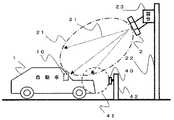
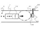
図1は本発明による自動料金収受(ETC)システムの実施の一形態を示す側面図、また、図2は図1の上空から見た平面図である。
【0016】
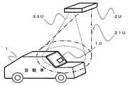
図1および図2に示されたETCシステムでは、ETC車載機10を搭載した自動車1が車線3の中央部を、車線3の上空に配備されたアンテナ装置2の下に向かって進行している。アンテナ装置2は内蔵するアンテナの放射ビーム領域21を有すると共に内蔵する光照射部が照射する可視光線31の照射領域を有するものとする。可視光線31の照射領域は、後述するように、放射ビーム領域21の内側中央部範囲であることが必要である。
【0017】
アンテナ装置2は、車線3の側面で直立する支柱22から車線3の上空に張り出す部分に装備された雲台23に取り付けられるものとする。雲台23は、車線3の中心線上空にあり、アンテナ装置2における電波の放射方向および光の照射方向をこの中心線に沿って移動可能で、アンテナ装置2の向きを適切に調整して固定できるものとする。
【0018】
また、この可視光線は刺激を与えることなく操縦者により確認できる必要があるため、照射される光の強さは、例えば昼夜、夕暮れ、曇天など周囲の明るさそれぞれに対応する区別があることが望ましい。
【0019】
可視光線の照射時期は、常時連続的であってもよいが、ETCシステムと連動してアンテナ装置2により車線3に自動車1が進入したことを検知した際に開始することとすれば、電力等における経費の節約ができる。
【0020】
また、センサ40が、車線3を進行する自動車1を検知する感知領域41を有し、車線3の側面で直立する支柱42に配備されているものとする。この場合、センサ40と上記アンテナ装置2との間の距離が適切に離れているならば、センサ40の検出信号によりアンテナ装置2の光照射を開始できるので、ETCシステムとは独立した光照射の制御ができる。
【0021】
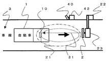
図3はセンサ40とアンテナ装置2との関係における実施の一形態を示すブロック図である。
【0022】
図3において、進行する自動車1はETC車載機10を備え、アンテナ装置2はアンテナ20と光照射部30とを備えるものとする。センサ40は、車線上の自動車1を感知した際にアンテナ装置2の光照射部30に通知するものとする。光照射部30はセンサ40から自動車1の進入通知を受けた際に光源を駆動して自動車1に向けて照射領域を有する可視光線31を照射するものとする。アンテナ20も通信を開始するがその時期と可視光線31の照射時期は無関係であるものとする。通常、本発明の目的を達成するため、アンテナ20による通信の開始に先立って、センサ40が自動車1を検知し、可視光線31の照射が開始できるように設定される。自動車1は可視光線31の照射を受けた自動車1の運転者がETC車載機10を可視光線31の照射領域の中央部になるように運転制御できる。従って、センサ40を通過した時点で可視光線31の照射が消えても、ETCシステムの機能を確実に実行することができる。
【0023】
次に、図3に図4を併せ参照して図3におけるシステムの主要動作手順について説明する。
【0024】
まず、センサ40が車線3で自動車1の進入を検知(手順S1)しこれを光照射部30に通知する。光照射部30は、検知の通知により駆動開始(手順S2)し、光源を駆動して可視光線31の照射(手順S3)を開始する。手順S3の可視光線31の照射は、センサ40から検出停止の通知なし(手順S4のNO)の間を継続し、上記手順S4が「YES」で検出停止の通知を受けた際に停止(手順S5)する。
【0025】
次に、図5を参照してアンテナ装置2の実施の一形態における外観について説明する。
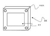
【0026】
図5に示されるアンテナ装置2は、内蔵されるアンテナ(図示されていない)による電波放射面24を長方形筐体の表面に有し、この長方形筐体の上部に小形の長方形筐体である光照射部30を有している。図5に示される光照射部30は光源部32を電波放射面24と同一の面に備えており、光源部32はアンテナから一定の距離を離して正対する壁面に照射した場合に円形の形状をなす照射領域を有する可視光線を発射している。
【0027】
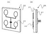
次に図6(A)、(B)を参照して、図3で示されるアンテナ20の実施の一形態を示す構造について説明する。
【0028】
図6(A)に示されるように、アンテナは平面アンテナ20であり、平面上で長方形をなすようにその四つの頂点位置それぞれに銅箔による円板形状のパッチアンテナ25を配し、銅箔によるマイクロストリップラインが上下それぞれで二つのパッチアンテナ同士を結ぶと共にこのマイクロストリップライン同士を中心点で結んでいる。更にマイクロストリップラインの中心点に配備される給電部が並列給電している。平面アンテナ20に用いられる放射素子には、パッチアンテナ25のような円形のもの以外に、方形のもの、マイクロストリップラインアンテナ、スロットアンテナなどを用いることもできる。また、平面アンテナ20の代わりに、ホーンアンテナ、レンズアンテナ、パラボラアンテナ、反射板付きクロスダイポールアレー、ヘリカルアンテナなど、種々のアンテナを用いることができる。
【0029】
図6(B)に示される平面アンテナ20はパッチアンテナ25およびこれらを結ぶマイクロストリップラインを誘電体基板26上に配置している。誘電体基板26には、通常、テフロン板、変成BT板、ガラエポ基板などが用いられ、裏面にグラウンド板27が張られると共に、裏面中心部では、パッチアンテナ25の給電部と接続して外部からの給電を受けるコネクタが配備されている。
【0030】
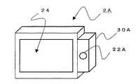
次に、図7を参照して図5と異なる位置に光照射部30Aを配備したアンテナ装置2Aについて説明する。図7に示される構成要素は、光照射部30Aの位置が電波放射面24の向かって右側である点が異なるのみでそれぞれの機能は図5の同一名称のものと同一であるので、その説明は省略する。従って、図5では光照射部30の光源部32を電波放射面24の上部に配置したが、上下左右の何れでもよく、また複数を配備してもよいことは当然のことである。
【0031】
次に、光照射部の可視光線の照射領域と電波放射面から放射される電波の放射ビーム領域との関係について説明する。すなわち、両者の関係は次の3点である。第1に、可視光線の照射領域は電波の放射ビーム領域より狭いこと、第2に、可視光線の照射領域の中心軸は電波の放射ビーム領域の中心軸とほぼ一致していること、第3に、可視光線の照射領域と電波の放射ビーム領域とが、乗用車、バス、トラックなどのあらゆる車種に搭載されるETC車載機をカバーできることである。
【0032】
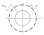
まず、図8は図7に示される光照射部30Aの可視光線の照射領域33Aと電波放射面24から放射される電波の放射ビーム領域21との関係を横断面で示したものである。図5に示される光照射部30の場合も同様である。すなわち、可視光線の照射領域33Aにおける横断面はアンテナから一定の距離を離して正対する壁面に照射した場合にほぼ円形形状をなし、電波の放射ビーム領域21と中心をほぼ一致させて放射ビーム領域21の内部に位置している。
【0033】
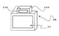
次に、図9に示されるアンテナ装置2Bは図5のおける光照射部30の代わりに光照射部30Bを配備している。光照射部30Bは、横長長方形の光源部32Bを有している。また、光源部32Bは電波放射面24の下側に配備されても、また両側に配備されてもよい。更に、縦長の光源部により左右の側に配備することもできる。すなわち、それぞれの配備については少なくとも一つあればよいこととなる。
【0034】
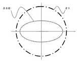
図10は、図9に示される光源部32Bによる可視光線の照射領域33Bにおける横断面の一形態を示している。図示されるように、可視光線の照射領域33Bは横長の楕円形となる。この場合も、可視光線の照射領域33Bは電波の放射ビーム領域21と中心をほぼ一致させて放射ビーム領域21の内部に位置している。電波放射面24の左右に配備される縦長の光源部の場合には可視光線の照射領域が縦長の楕円形になることは言うまでもない。
【0035】
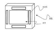
図11は細長い光源部32Cを長方形の電波放射面24において上下左右の四方に配備したアンテナ装置2Cを示している。
【0036】
図12は、円形の光源部32Dを長方形の電波放射面24における対角線上の四隅に配備したアンテナ装置2Dを示している。
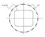
【0037】
図13は、図11または図12に示される光源部32Cまたは光源部32Dによる可視光線の照射領域33CDにおける横断面の一形態を示している。図示されるように、可視光線の照射領域33CDは角の取れた長方形となる。この場合、可視光線の照射領域33CDを電波の放射ビーム領域21と中心を一致させることができると共に放射ビーム領域21の内側中央部に位置させることができる。
【0038】
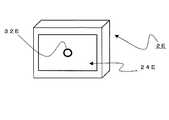
次に、図14は、円形の光源部32Eを長方形の電波放射面24Eにおける中央に配備したアンテナ装置2Eを示している。
【0039】
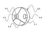
図15は、パラボラ反射鏡50の中央にホーン51を配した構造のアンテナ装置2Fを示している。パラボラ反射鏡50には、3本のサポータ52で保持されるサブレフレクタ53が前面中央部に備えられ、サブレフレクタ53の中央に光源部54が設けられている。
【0040】
図14または図15の構造における可視光線の照射領域は、図8に示されるように、横断面がほぼ円形をなし、照射領域を電波の放射ビーム領域21と中心を一致させて放射ビーム領域21の中央部に位置させることができる。
【0041】
次に、車線を遮断機により開閉する、例えば駐車場などにおけるETCシステムについて説明する。
【0042】
図16は、ETC車載機10を備えた自動車1の前方にアンテナ装置6を備えた遮断機7が設けられた料金所における実施の一形態を示す斜視図である。
【0043】
図示されるように、自動車1が通過する車線3の上部空間で自動車1の通過を阻止する遮断機7が支柱8により回動または上下動を可能に支持されている。遮断機7に備えられるアンテナ装置6が有するアンテナから放射ビーム領域61を有する電波が放射され、ETC車載機10との通信により自動車1への自動料金収受が行なわれたのち、遮断機7が支柱8の駆動により揚げられて自動車1がこの料金所を通過できる。
【0044】
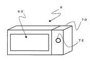
図17は、図16におけるアンテナ装置6を示している。図17に示されるアンテナ装置6は、内蔵されるアンテナ(図示されていない)による電波放射面62を長方形筐体の表面に有し、この長方形筐体の向かって右側に小形の長方形筐体である光照射部70を有している。光照射部70は、円形の横断面をなす照射領域を有する可視光線を発射する光源部72を、電波放射面62と同一の面に備えている。
【0045】
次に、図16に図17を併せ参照してこの実施例について説明する。
【0046】
本実施例によるシステムでは、図1から図4までを参照して説明したと同様、アンテナ装置6が光照射部70を内蔵し、センサ40により自動車1の車線3への進入を検知した際、光照射部70の光源部72から可視光線の照射領域71に可視光線を照射する。可視光線の照射領域71は電波放射面62から放射される放射ビーム領域61の中央部にあり、運転者により自動車1のETC車載機10を可視光線の照射領域71内に進めることにより、ETC車載機10を放射ビーム領域61の中央部に容易に位置させることができる。
【0047】
次に、図18は乗用車1A、また図19は大型バス1B、それぞれの正面にアンテナ装置6がある場合の放射ビーム領域61および照射領域71それぞれの位置関係を示している。図示されるように、可視光線の照射領域71は、縦長の領域を有しており、放射ビーム領域61の範囲内で中央部に位置して高さの異なるETC車載機10A,10Bを照射できる。しかし、ETCシステムが自動車の大きさを検知して雲台を制御しアンテナ装置の仰角を変化させることができる場合には、光照射部もアンテナと連動して回動するので照射領域を縮小することができる。
【0048】
図20はアンテナ装置2Uが車線の上部に配備された例である。これも上述したと同様、可視光線の照射領域33Uは放射ビーム領域21Uの範囲内で中央部に位置してETC車載機10を照射できなければならない。この場合も、乗用車および大型バスのように高さの異なるETC車載機を照射できることが望ましい。
【0049】
次に、図21および図22を併せ参照してハンディタイプのアンテナ装置の実施例について説明する。図21はハンディタイプのアンテナ装置8の一形態を示す斜視図であり、図22はこのアンテナ装置8を使用する際の一形態を示す斜視図である。
【0050】
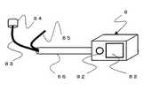
アンテナ装置8は、上述したものと同様に、アンテナと光照射部とを内蔵しており、アンテナの電波放射面82と光照射部の光源部92とは同一平面上にあり、光の照射領域91は放射ビーム領域81の範囲内で中央部に位置してETC車載機10を照射するものである。アンテナ装置8は、ETCシステムにおける通信用の同軸ケーブル83の一端に接続され、この他端には同軸コネクタ84が接続されている。また、電源ケーブル85が接続されているので、アンテナ装置8を手軽に扱う便宜のため、同軸ケーブル83および電源ケーブル85を内部に収納するパイプ状で可撓性のアーム部86がアンテナ装置8に結合している。
【0051】
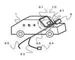
図示されるように、自動車1でETC車載機10の前面10センチメートルから1メートル程度の距離でスイッチをオンし、光源部92の可視光線がETC車載機10を照射するように、手動によりアンテナの電波放射面82をETC車載機10に向けることにより、ETCシステムの通信を行なうものである。
【0052】
上述同様、可視光線の照射領域91が電波の照射ビーム領域81と同等かまたは狭い範囲であれば、可視光線の照射領域91内にETC車載機10を位置させることによりETCのための通信が確実に行われる。この場合では、自動車1の運転者でなくアンテナ装置8の操作者が確実な通信を得るために作業することとなる。
【0053】
このようなハンディタイプのアンテナ装置は、次のような長所を有している。
【0054】
第1は、有料道路または有料駐車場などの料金収受場所において、システム本体側のETC用アンテナ装置が車線上に設置されていなくとも、料金収受を簡単に可能にするということである。
【0055】
第2は、ETCシステムが配備された車線でも、通信不良などで車両が通過できない場合、またはアンテナ装置の故障で通信不能な場合、自動車の運転者は何ら余計な動作を必要としないで、料金収受が可能であるということである。
【0056】
第3は、ガソリンスタンドまたはドライブスルーなどで、クレジットカードなどのカードによる料金処理を低価格で行なう処理システムとして手軽に採用することができることである。
【0057】
上記説明では、図面を参照して、センサが自動車を検知した際にアンテナの電波が形成する放射ビーム領域内部の中央部に可視光線を照射させるとした。しかしながら、センサなしでもよい。例えば、常時連続的に照射するか、または、元来ETCシステムから独立して設備できるものであるが、ETCシステムと連動させてシステムを構成し電波による通信とタイミングを合わせて効率よく照射させることも可能である。
【0058】
また、上記説明では、アンテナ装置、アンテナ、および光照射部それぞれの形体および材質、並びに電波放射面および光源部それぞれの形状を図示して説明したが、それぞれその一形態であり、図示されていない他の形状でもよい。また、光源部の位置も、可視光線の照射領域が放射ビーム領域の範囲内でほぼ中央部に位置するように調整され、可視光線の照射領域にあるETC車載機がアンテナと確実に通信できる位置ならば、電波放射面内およびその周辺を含む何れの場所に、またいくつあってもよい。
【0059】
また、機能構成または構造についても、上記機能を満たす限りその変更は自由であり、上記説明が本発明を限定するものではない。
【0060】
【発明の効果】
以上説明したように本発明によれば、次のような効果を得ることができる。
【0061】
第1の効果は、ETCシステムにおける通信のエラーが低減し信頼性が向上することである。
【0062】
その理由は、電波を放射するアンテナを内蔵するアンテナ装置が電波の放射ビーム領域の範囲内でほぼ中央部の位置範囲に可視光線を照射する光照射部を有しているからである。この照射光により、自動車の運転者、ハンディタイプのアンテナ装置の操作者など、操縦者がETC車載機を可視光線の照射領域に入れるように操作するため、ETC車載機が電波の放射ビーム領域の範囲内でほぼ中央部に位置でき、通信によりよい条件を整えることになる。
【0063】
第2の効果は、安全性が確保できることである。
【0064】
その理由は、第1の効果により通信のエラーが低減するからである。すなわち、早すぎる速度で通信エラーが生じゲートが閉じた場合には、自動車がゲートに激突する恐れがあるが、通信条件が改善されるのでこのように激突する機会が減少することとなる。
【0065】
第3の効果は、操縦者に精神的安定感を与えることである。
【0066】
その理由は、可視光線が自動車のETC車載機を照射することを操縦者が認識できるので、ETC車載機がETCシステムと確実に通信しているという認識も得られるからである。
【図面の簡単な説明】
【図1】本発明によるETCシステムの実施の一形態を示す側面図である。
【図2】図1の上空から見た平面図である。
【図3】図1におけるセンサとアンテナ装置との関係の実施の一形態を示すブロック図である。
【図4】図3における主要動作手順の一形態を示すフローチャートである。
【図5】本発明によるアンテナ装置の外観の一形態を示す斜視図である。
【図6】図6(A)は平面アンテナとしてパッチアンテナを用いた外観の一形態を示す斜視図である。図6(B)は図6(A)における平面アンテナの一構成を示す側面図である。
【図7】図5において光照射部の位置を変更したアンテナ装置における外観の一形態を示す斜視図である。
【図8】図5または図7におけるアンテナ装置による光の照射領域の一形態を示す横断面パターン説明図である。
【図9】図5において光源部の形状を変更したアンテナ装置における外観の一形態を示す斜視図である。
【図10】図9におけるアンテナ装置による光の照射領域の一形態を示す横断面パターン説明図である。
【図11】本発明による横長形状の光源部を上下左右に有するアンテナ装置における外観の一形態を示す斜視図である。
【図12】本発明による円形の光源部を四隅に有するアンテナ装置における外観の一形態を示す斜視図である。
【図13】図11または図12におけるアンテナ装置による光の照射領域の一形態を示す横断面パターン説明図である。
【図14】本発明による円形の光源部を中央に有するアンテナ装置における外観の一形態を示す斜視図である。
【図15】本発明によるパラボラアンテナを用いたアンテナ装置における外観の一形態を示す斜視図である。
【図16】本発明による遮断機に搭載するアンテナ装置を用いたシステムにおける実施の一形態を示す斜視図である。
【図17】図16の遮断機に搭載するアンテナ装置における外観の一形態を示す斜視図である。
【図18】図16における可視光線の照射領域を乗用車に適用した際の実施の一形態を示す斜視図である。
【図19】図16における可視光線の照射領域を大型バスに適用した際の実施の一形態を示す斜視図である。
【図20】本発明によるアンテナ装置を上空に設置した場合の実施の一形態を示す斜視図である。
【図21】本発明によるハンディタイプのアンテナ装置の実施の一形態を示す斜視図である。
【図22】図21のアンテナ装置の使用方法を説明する実施の一形態を示す斜視図である。
【図23】従来のETCシステムにおける一例を示す平面図である。
【符号の説明】
1 自動車
1A 乗用車
1B 大型バス
2、2A、2B、2C、2D、2E、2F、2U、6、8 アンテナ装置
3 車線
10、10A、10B ETC車載機
20 平面アンテナ
21、21U、61、81 放射ビーム領域
22、42 支柱
23 雲台
24、24E、62,82 電波放射面
25 パッチアンテナ
26 誘電体基板
27 グラウンド板
30、30A、30B、70 光照射部
31 可視光線
32、32A、32B、32C、32D、32E、54、72、92 光源部
33A、33B、33CD、33U、71、91 照射領域
40 センサ
41 感知領域
50 パラボラ反射鏡
51 中央にホーン
52 サポータ
53 サブレフレクタ
83 同軸ケーブル
84 同軸コネクタ
85 電源ケーブル
86 アーム部[0001]
TECHNICAL FIELD OF THE INVENTION
The present invention relates to an antenna device, and an automatic toll collection system and an automatic toll collection method using the same, and in particular, it is possible to secure communication between an in-vehicle device for automatic toll collection and the antenna device to improve traffic smoothness. The present invention relates to an antenna device, and an automatic toll collection system and an automatic toll collection method using the same.
[0002]
[Prior art]
Conventionally, in an antenna device of this type and an automatic toll collection (hereinafter abbreviated as ETC) system using the same, for example, as shown in FIG. An
[0003]
Usually, the
[0004]
However, since various types of radio interference exist, in order to reduce communication errors, a beam pattern of an antenna is devised, and a reflected wave is suppressed by laying a radio wave absorber.
[0005]
[Problems to be solved by the invention]
However, in the above-described conventional antenna device and the automatic toll collection system using the same, since the radiation beam area of the antenna device is usually targeted on the center line of the lane, the position of the ETC on-board device mounted on the vehicle is reduced. If the vehicle is approaching the passenger seat and the vehicle entering the lane is approaching the passenger seat side of the lane, there is a high possibility that communication for ETC becomes uncertain. For this reason, when communication is not possible, the vehicle must be stopped before the exit or the passing speed is further reduced, which causes a problem that the smooth passing of the vehicle on the lane is hindered.
[0006]
SUMMARY OF THE INVENTION An object of the present invention is to solve such a problem, and to control an on-vehicle ETC device mounted on an automobile so as to be located at a center position of a radiation beam area of the antenna device, and an automatic toll using the same. To provide a collection system.
[0007]
[Means for Solving the Problems]
An antenna device according to the present invention includes an antenna having a constant directivity to a radiation beam, and a light irradiating unit having an irradiation region with visible light in a central partial range within a radiation beam region of the antenna. With this configuration, the driver of the car who feels the visible light irradiation at night or in the day can pass through the on-board ETC device at the center of the visible light irradiation area. Further, when the visible light emitted from the light source of the light irradiating unit in the antenna device irradiates a directly facing wall surface at a predetermined distance from the antenna in the irradiation area, a substantially circular shape, a horizontally long shape, or a vertically long shape Irradiation to make.
[0008]
In addition, the specific arrangement of the antenna and the light irradiating section in the above-mentioned antenna device is at least one location around the center of the antenna, for example, up, down, left, right, and four corners. The irradiation shape of the visible light in the irradiation area when arranged at the top, bottom, left, right, or four corners can be formed substantially rectangular.
[0009]
In the antenna device, the antenna may include a parabolic reflector, a horn-type antenna, and a sub-reflector held by a supporter, and the light source of the light irradiation unit may be located substantially at the center of the sub-reflector.
[0010]
One automatic toll collection system according to the present invention employs any one of the above-described antenna devices, wherein the antenna device is held with a support above a lane through which a car passes, and an antenna included in the antenna device is provided. When directing the radiation beam area to the automatic toll collection vehicle-mounted device mounted on the vehicle, the light source of the light irradiation unit irradiates the inner central partial range of the radiation beam area with visible light. I have. Further, further detecting the car entering the lane in front of the antenna with respect to the approach direction of the car, driving the light irradiator when detecting the approach of the car from the light source of the light irradiator It is desirable to further include a sensor that emits visible light.
[0011]
Another automatic toll collection system according to the present invention uses any one of the above-described antenna devices, and the antenna device traverses in a lane in which a vehicle passes to a position where the vehicle is blocked. When the radiation beam area of the antenna provided in the antenna device is directed to the automatic toll collection vehicle-mounted device mounted on the vehicle, the light source of the light irradiating unit is provided with the radiation beam. It is characterized in that the inner central partial range of the region is irradiated with visible light. In this case, it is desirable to further include a sensor that detects an automobile entering the lane, and drives the light irradiating unit to emit visible light from a light source of the light irradiating unit when detecting the entry of the automobile.
[0012]
Since the irradiation range of the light is the central partial range inside the radiation beam area of the antenna, it is particularly effective when the surroundings are dark and the confirmation of the position of the lane or the antenna device is uncertain. In addition, the visible light can be irradiated economically and effectively by the sensor without being controlled by the ETC system.
[0013]
Another antenna device different from the above-described antenna device is characterized in that it is a handy type connected at one end of an arm portion having a coaxial cable and a power cable therein. When using this antenna device, a person holding the antenna device directs the irradiation area of the light irradiated by the light irradiating unit to the automatic toll collection vehicle device of the car entering the lane for toll collection. Automatic toll collection can be performed by the ETC system using the radiation beam of the antenna.
[0014]
BEST MODE FOR CARRYING OUT THE INVENTION
Next, embodiments of the present invention will be described with reference to the drawings.
[0015]
FIG. 1 is a side view showing an embodiment of an automatic toll collection (ETC) system according to the present invention, and FIG. 2 is a plan view seen from above of FIG.
[0016]
In the ETC system shown in FIGS. 1 and 2, the
[0017]
It is assumed that the
[0018]
In addition, since this visible light needs to be able to be confirmed by the pilot without giving a stimulus, the intensity of the emitted light may have a distinction corresponding to each of the ambient brightness, for example, day and night, dusk, cloudy sky. desirable.
[0019]
The irradiation time of the visible light may be continuous at all times. However, if it is assumed that the irradiation of the visible light is started when the
[0020]
Further, it is assumed that the
[0021]
FIG. 3 is a block diagram showing one embodiment of the relationship between the
[0022]
In FIG. 3, it is assumed that a traveling
[0023]
Next, a main operation procedure of the system in FIG. 3 will be described with reference to FIGS.
[0024]
First, the
[0025]
Next, the appearance of the
[0026]
The
[0027]
Next, a structure of the
[0028]
As shown in FIG. 6A, the antenna is a
[0029]
In the
[0030]
Next, an antenna device 2A in which the light irradiation unit 30A is provided at a position different from that in FIG. 5 will be described with reference to FIG. The components shown in FIG. 7 are the same as those having the same names in FIG. 5 except that the position of the light irradiation unit 30A is on the right side of the radio
[0031]
Next, the relationship between the visible light irradiation area of the light irradiation unit and the radiation beam area of the radio wave radiated from the radio wave radiation surface will be described. That is, the relationship between the two is as follows. First, the visible light irradiation area is narrower than the radio wave radiation beam area. Second, the center axis of the visible light irradiation area is substantially coincident with the center axis of the radio wave radiation beam area. In addition, the irradiation region of visible light and the radiation beam region of radio waves can cover an ETC vehicle-mounted device mounted on all types of vehicles such as passenger cars, buses, and trucks.
[0032]
First, FIG. 8 is a cross-sectional view showing the relationship between the visible light irradiation area 33A of the light irradiation unit 30A shown in FIG. 7 and the
[0033]
Next, the
[0034]
FIG. 10 shows one form of a cross section in a visible light irradiation area 33B by the light source unit 32B shown in FIG. As shown, the visible light irradiation area 33B has a horizontally long elliptical shape. Also in this case, the visible light irradiation area 33B is positioned inside the
[0035]
FIG. 11 shows an antenna device 2C in which elongated
[0036]
FIG. 12 shows an antenna device 2D in which
[0037]
FIG. 13 illustrates one form of a cross section in a visible light irradiation region 33CD by the
[0038]
Next, FIG. 14 shows an antenna device 2E in which a circular light source unit 32E is provided at the center of a rectangular radio wave radiation surface 24E.
[0039]
FIG. 15 shows an
[0040]
As shown in FIG. 8, the visible light irradiation area in the structure of FIG. 14 or FIG. 15 has a substantially circular cross section, and the irradiation area is aligned with the center of the
[0041]
Next, an ETC system in which a lane is opened and closed by a circuit breaker, for example, in a parking lot or the like will be described.
[0042]
FIG. 16 is a perspective view showing an embodiment in a tollgate where a
[0043]
As shown in the figure, a
[0044]
FIG. 17 shows the
[0045]
Next, this embodiment will be described with reference to FIGS.
[0046]
In the system according to the present embodiment, as described with reference to FIGS. 1 to 4, when the
[0047]
Next, FIG. 18 shows a passenger car 1A, and FIG. 19 shows a positional relationship between the
[0048]
FIG. 20 shows an example in which the antenna device 2U is provided above a lane. Similarly to the above, the visible light irradiation area 33U must be located at the center within the range of the radiation beam area 21U to be able to irradiate the on-
[0049]
Next, an embodiment of a handy type antenna device will be described with reference to FIGS. FIG. 21 is a perspective view showing one mode of the handy
[0050]
The
[0051]
As shown in the figure, the
[0052]
As described above, if the visible
[0053]
Such a handy type antenna device has the following advantages.
[0054]
First, at a toll collection place such as a toll road or a toll parking lot, even if the ETC antenna device on the system body side is not installed on the lane, the toll collection can be easily performed.
[0055]
Second, if the vehicle cannot pass through the ETC system even if the vehicle is unable to pass due to poor communication or the antenna device fails, the driver of the car does not need any extra operation, It is possible to receive.
[0056]
Thirdly, the present invention can be easily adopted as a processing system for performing low-cost charge processing by using a card such as a credit card in a gas station or a drive-through.
[0057]
In the above description, with reference to the drawings, it is assumed that, when the sensor detects the automobile, visible light is applied to the central portion inside the radiation beam area formed by the radio wave of the antenna. However, there may be no sensor. For example, it is possible to irradiate continuously and always or independently from the ETC system, but it is necessary to configure the system in conjunction with the ETC system and to irradiate efficiently with radio wave communication and timing. Is also possible.
[0058]
In the above description, the shape and material of each of the antenna device, the antenna, and the light irradiating unit, and the shape of each of the radio wave radiating surface and the light source unit are illustrated and described, but each is one form and is not illustrated. Other shapes are also possible. The position of the light source unit is also adjusted so that the visible light irradiation area is located substantially at the center within the range of the radiation beam area, so that the ETC on-board unit in the visible light irradiation area can reliably communicate with the antenna. Then, there may be any number of places, including in and around the radio wave radiation plane, and any number of places.
[0059]
Also, the functional configuration or structure can be freely changed as long as the above functions are satisfied, and the above description does not limit the present invention.
[0060]
【The invention's effect】
As described above, according to the present invention, the following effects can be obtained.
[0061]
The first effect is that communication errors in the ETC system are reduced and reliability is improved.
[0062]
The reason is that an antenna device having a built-in antenna for radiating a radio wave has a light irradiating unit for irradiating visible light to a position range substantially at the center within a range of a radiation beam region of a radio wave. With this irradiation light, a driver, such as a car driver or an operator of a handy type antenna device, operates the on-board ETC device so as to enter the visible light irradiation region. It can be located almost in the center within the range, and better conditions for communication can be set.
[0063]
The second effect is that safety can be ensured.
[0064]
The reason is that communication errors are reduced by the first effect. In other words, if a communication error occurs at an excessively high speed and the gate closes, the vehicle may crash into the gate. However, the communication conditions are improved, and the chances of such collision are reduced.
[0065]
The third effect is to give the pilot a sense of mental stability.
[0066]
The reason is that the operator can recognize that the visible light irradiates the ETC on-vehicle device of the automobile, so that the recognition that the ETC on-vehicle device is securely communicating with the ETC system is also obtained.
[Brief description of the drawings]
FIG. 1 is a side view showing an embodiment of an ETC system according to the present invention.
FIG. 2 is a plan view seen from above of FIG. 1;
FIG. 3 is a block diagram showing an embodiment of a relationship between a sensor and an antenna device in FIG. 1;
FIG. 4 is a flowchart showing one mode of a main operation procedure in FIG. 3;
FIG. 5 is a perspective view showing an embodiment of the appearance of the antenna device according to the present invention.
FIG. 6A is a perspective view showing one embodiment of an appearance using a patch antenna as a planar antenna. FIG. 6B is a side view showing one configuration of the planar antenna in FIG. 6A.
FIG. 7 is a perspective view showing one embodiment of the appearance of the antenna device in which the position of the light irradiation unit is changed in FIG.
8 is a cross-sectional pattern explanatory diagram showing one form of a light irradiation area by the antenna device in FIG. 5 or FIG. 7;
FIG. 9 is a perspective view showing one form of the appearance of the antenna device in which the shape of the light source unit is changed in FIG.
10 is a cross-sectional pattern explanatory view showing one mode of a light irradiation area by the antenna device in FIG. 9;
FIG. 11 is a perspective view showing one embodiment of an appearance of an antenna device having a horizontally long light source unit according to the present invention in up, down, left and right directions.
FIG. 12 is a perspective view showing an embodiment of an appearance of an antenna device having circular light sources at four corners according to the present invention.
FIG. 13 is a cross-sectional pattern explanatory view showing one form of a light irradiation area by the antenna device in FIG. 11 or FIG.
FIG. 14 is a perspective view showing an embodiment of an appearance of an antenna device having a circular light source section at the center according to the present invention.
FIG. 15 is a perspective view showing an embodiment of an appearance of an antenna device using a parabolic antenna according to the present invention.
FIG. 16 is a perspective view showing one embodiment of a system using an antenna device mounted on a circuit breaker according to the present invention.
FIG. 17 is a perspective view showing an appearance of an antenna device mounted on the circuit breaker of FIG.
FIG. 18 is a perspective view showing an embodiment when the irradiation region of visible light in FIG. 16 is applied to a passenger car.
FIG. 19 is a perspective view showing an embodiment in which the visible light irradiation area in FIG. 16 is applied to a large bus.
FIG. 20 is a perspective view showing an embodiment when the antenna device according to the present invention is installed in the sky.
FIG. 21 is a perspective view showing an embodiment of a handy type antenna device according to the present invention.
FIG. 22 is a perspective view illustrating one embodiment of a method of using the antenna device of FIG. 21;
FIG. 23 is a plan view showing an example of a conventional ETC system.
[Explanation of symbols]
1 car
1A passenger car
1B Large bus
2, 2A, 2B, 2C, 2D, 2E, 2F, 2U, 6, 8 antenna device
3 lanes
10, 10A, 10B ETC on-board equipment
20 Planar antenna
21, 21U, 61, 81 radiation beam area
22, 42 prop
23 Head
24, 24E, 62, 82 Radio wave emission surface
25 Patch Antenna
26 Dielectric substrate
27 Ground Board
30, 30A, 30B, 70 Light irradiation unit
31 visible light
32, 32A, 32B, 32C, 32D, 32E, 54, 72, 92 Light source unit
33A, 33B, 33CD, 33U, 71, 91 Irradiation area
40 sensors
41 Sensing area
50 parabolic reflector
51 Horn in the center
52 Supporters
53 Sub reflector
83 coaxial cable
84 coaxial connector
85 Power cable
86 arm
Claims (16)
Translated fromJapanesePriority Applications (4)
| Application Number | Priority Date | Filing Date | Title |
|---|---|---|---|
| JP2000177757AJP3570500B2 (en) | 2000-06-14 | 2000-06-14 | Antenna device, automatic toll collection system and method using the same |
| CA 2350317CA2350317C (en) | 2000-06-14 | 2001-06-13 | Antenna apparatus and electronic toll collection system and electronic toll collection method using the same |
| US09/879,157US6683580B2 (en) | 2000-06-14 | 2001-06-13 | Antenna apparatus and electronic toll collection system and electronic toll collection method using the same |
| AU51911/01AAU783752B2 (en) | 2000-06-14 | 2001-06-14 | Antenna apparatus and electronic toll collection system and electronic toll collection method using the same |
Applications Claiming Priority (1)
| Application Number | Priority Date | Filing Date | Title |
|---|---|---|---|
| JP2000177757AJP3570500B2 (en) | 2000-06-14 | 2000-06-14 | Antenna device, automatic toll collection system and method using the same |
Publications (2)
| Publication Number | Publication Date |
|---|---|
| JP2001357423A JP2001357423A (en) | 2001-12-26 |
| JP3570500B2true JP3570500B2 (en) | 2004-09-29 |
Family
ID=18679302
Family Applications (1)
| Application Number | Title | Priority Date | Filing Date |
|---|---|---|---|
| JP2000177757AExpired - LifetimeJP3570500B2 (en) | 2000-06-14 | 2000-06-14 | Antenna device, automatic toll collection system and method using the same |
Country Status (4)
| Country | Link |
|---|---|
| US (1) | US6683580B2 (en) |
| JP (1) | JP3570500B2 (en) |
| AU (1) | AU783752B2 (en) |
| CA (1) | CA2350317C (en) |
Families Citing this family (185)
| Publication number | Priority date | Publication date | Assignee | Title |
|---|---|---|---|---|
| AT500811A1 (en)* | 2001-06-12 | 2006-03-15 | Siemens Ag Oesterreich | DEVICES AND METHODS FOR SIMPLIFYING OCR-BASED ENFORCEMENT IN AUTOMATIC MACHINE SYSTEMS |
| AT500914B8 (en)* | 2001-10-24 | 2007-02-15 | Siemens Ag Oesterreich | AUTOMATIC FUNCTIONAL CHECK OF AN ANTENNA UNIT OF A VEHICLE SIDE UNIT OF AN ELECTRONIC MACHINE SYSTEM |
| WO2005111946A2 (en) | 2004-05-10 | 2005-11-24 | Rentatoll, Inc. | Toll fee system and method |
| US7995101B2 (en) | 2004-11-09 | 2011-08-09 | Canon Kabushiki Kaisha | Image processing system, image supply apparatus, image receiving apparatus, lighting apparatus and controlling method therefor |
| JP4597008B2 (en)* | 2004-11-09 | 2010-12-15 | キヤノン株式会社 | Image display system, image display apparatus, control method thereof, and storage medium |
| US8768753B2 (en) | 2005-09-07 | 2014-07-01 | Rent A Toll, Ltd. | System, method and computer readable medium for billing tolls |
| US20070124197A1 (en)* | 2005-09-07 | 2007-05-31 | Rent-A-Toll, Ltd. | System, method and computer readable medium for billing |
| WO2007044961A2 (en)* | 2005-10-13 | 2007-04-19 | Rent-A-Toll, Ltd. | System, method, and computer readable medium for toll service activation and billing |
| US7683843B2 (en) | 2005-11-08 | 2010-03-23 | M/A-Com Technology Solutions Holdings, Inc. | Multiband antennas and devices |
| US8768754B2 (en) | 2006-01-09 | 2014-07-01 | Rent-A-Toll, Ltd. | Billing a rented third party transport including an on-board unit |
| CA2636507C (en) | 2006-01-09 | 2015-03-03 | Benjamin P. Robinson | Billing a rented third party transport including an on-board unit |
| CA2652141C (en) | 2006-05-18 | 2015-11-03 | Rent A Toll, Ltd. | Determining a toll amount |
| US20070285280A1 (en)* | 2006-06-07 | 2007-12-13 | Rent-A-Toll, Ltd. | Providing toll services utilizing a cellular device |
| JP2008009733A (en)* | 2006-06-29 | 2008-01-17 | Mitsubishi Heavy Ind Ltd | Toll collection system, parking management device, and in-vehicle device |
| US7411560B2 (en)* | 2006-09-30 | 2008-08-12 | M/A-Com, Inc. | Low profile antennas and devices |
| US7774228B2 (en) | 2006-12-18 | 2010-08-10 | Rent A Toll, Ltd | Transferring toll data from a third party operated transport to a user account |
| US8363899B2 (en) | 2008-10-10 | 2013-01-29 | Rent A Toll, Ltd. | Method and system for processing vehicular violations |
| JP2009189873A (en)* | 2009-06-01 | 2009-08-27 | Sanyo Product Co Ltd | Game machine |
| CN103093507B (en)* | 2011-10-31 | 2015-04-22 | 深圳光启高等理工研究院 | Method and system for freeway toll collected through light emitting diode (LED) lamp |
| US9113347B2 (en) | 2012-12-05 | 2015-08-18 | At&T Intellectual Property I, Lp | Backhaul link for distributed antenna system |
| US10009065B2 (en) | 2012-12-05 | 2018-06-26 | At&T Intellectual Property I, L.P. | Backhaul link for distributed antenna system |
| JP2014165754A (en)* | 2013-02-26 | 2014-09-08 | Mitsubishi Heavy Ind Ltd | Directional characteristic variable antenna |
| US9999038B2 (en) | 2013-05-31 | 2018-06-12 | At&T Intellectual Property I, L.P. | Remote distributed antenna system |
| US9525524B2 (en) | 2013-05-31 | 2016-12-20 | At&T Intellectual Property I, L.P. | Remote distributed antenna system |
| US8897697B1 (en) | 2013-11-06 | 2014-11-25 | At&T Intellectual Property I, Lp | Millimeter-wave surface-wave communications |
| US9209902B2 (en) | 2013-12-10 | 2015-12-08 | At&T Intellectual Property I, L.P. | Quasi-optical coupler |
| US10076015B2 (en)* | 2014-08-01 | 2018-09-11 | Philips Lighting Holding B.V. | Luminaire with radio module |
| US9692101B2 (en) | 2014-08-26 | 2017-06-27 | At&T Intellectual Property I, L.P. | Guided wave couplers for coupling electromagnetic waves between a waveguide surface and a surface of a wire |
| US9768833B2 (en) | 2014-09-15 | 2017-09-19 | At&T Intellectual Property I, L.P. | Method and apparatus for sensing a condition in a transmission medium of electromagnetic waves |
| US10063280B2 (en) | 2014-09-17 | 2018-08-28 | At&T Intellectual Property I, L.P. | Monitoring and mitigating conditions in a communication network |
| US9628854B2 (en) | 2014-09-29 | 2017-04-18 | At&T Intellectual Property I, L.P. | Method and apparatus for distributing content in a communication network |
| US9615269B2 (en) | 2014-10-02 | 2017-04-04 | At&T Intellectual Property I, L.P. | Method and apparatus that provides fault tolerance in a communication network |
| US9685992B2 (en) | 2014-10-03 | 2017-06-20 | At&T Intellectual Property I, L.P. | Circuit panel network and methods thereof |
| US9503189B2 (en) | 2014-10-10 | 2016-11-22 | At&T Intellectual Property I, L.P. | Method and apparatus for arranging communication sessions in a communication system |
| US9762289B2 (en) | 2014-10-14 | 2017-09-12 | At&T Intellectual Property I, L.P. | Method and apparatus for transmitting or receiving signals in a transportation system |
| US9973299B2 (en) | 2014-10-14 | 2018-05-15 | At&T Intellectual Property I, L.P. | Method and apparatus for adjusting a mode of communication in a communication network |
| US9653770B2 (en) | 2014-10-21 | 2017-05-16 | At&T Intellectual Property I, L.P. | Guided wave coupler, coupling module and methods for use therewith |
| US9520945B2 (en) | 2014-10-21 | 2016-12-13 | At&T Intellectual Property I, L.P. | Apparatus for providing communication services and methods thereof |
| US9577306B2 (en) | 2014-10-21 | 2017-02-21 | At&T Intellectual Property I, L.P. | Guided-wave transmission device and methods for use therewith |
| US9769020B2 (en) | 2014-10-21 | 2017-09-19 | At&T Intellectual Property I, L.P. | Method and apparatus for responding to events affecting communications in a communication network |
| US9627768B2 (en) | 2014-10-21 | 2017-04-18 | At&T Intellectual Property I, L.P. | Guided-wave transmission device with non-fundamental mode propagation and methods for use therewith |
| US9780834B2 (en) | 2014-10-21 | 2017-10-03 | At&T Intellectual Property I, L.P. | Method and apparatus for transmitting electromagnetic waves |
| US9312919B1 (en) | 2014-10-21 | 2016-04-12 | At&T Intellectual Property I, Lp | Transmission device with impairment compensation and methods for use therewith |
| US9564947B2 (en) | 2014-10-21 | 2017-02-07 | At&T Intellectual Property I, L.P. | Guided-wave transmission device with diversity and methods for use therewith |
| US10243784B2 (en) | 2014-11-20 | 2019-03-26 | At&T Intellectual Property I, L.P. | System for generating topology information and methods thereof |
| US9680670B2 (en) | 2014-11-20 | 2017-06-13 | At&T Intellectual Property I, L.P. | Transmission device with channel equalization and control and methods for use therewith |
| US9654173B2 (en) | 2014-11-20 | 2017-05-16 | At&T Intellectual Property I, L.P. | Apparatus for powering a communication device and methods thereof |
| US9742462B2 (en) | 2014-12-04 | 2017-08-22 | At&T Intellectual Property I, L.P. | Transmission medium and communication interfaces and methods for use therewith |
| US9544006B2 (en) | 2014-11-20 | 2017-01-10 | At&T Intellectual Property I, L.P. | Transmission device with mode division multiplexing and methods for use therewith |
| US10009067B2 (en) | 2014-12-04 | 2018-06-26 | At&T Intellectual Property I, L.P. | Method and apparatus for configuring a communication interface |
| US9800327B2 (en) | 2014-11-20 | 2017-10-24 | At&T Intellectual Property I, L.P. | Apparatus for controlling operations of a communication device and methods thereof |
| US9954287B2 (en) | 2014-11-20 | 2018-04-24 | At&T Intellectual Property I, L.P. | Apparatus for converting wireless signals and electromagnetic waves and methods thereof |
| US9461706B1 (en) | 2015-07-31 | 2016-10-04 | At&T Intellectual Property I, Lp | Method and apparatus for exchanging communication signals |
| US9997819B2 (en) | 2015-06-09 | 2018-06-12 | At&T Intellectual Property I, L.P. | Transmission medium and method for facilitating propagation of electromagnetic waves via a core |
| US10340573B2 (en) | 2016-10-26 | 2019-07-02 | At&T Intellectual Property I, L.P. | Launcher with cylindrical coupling device and methods for use therewith |
| US10144036B2 (en) | 2015-01-30 | 2018-12-04 | At&T Intellectual Property I, L.P. | Method and apparatus for mitigating interference affecting a propagation of electromagnetic waves guided by a transmission medium |
| US9876570B2 (en) | 2015-02-20 | 2018-01-23 | At&T Intellectual Property I, Lp | Guided-wave transmission device with non-fundamental mode propagation and methods for use therewith |
| US9749013B2 (en) | 2015-03-17 | 2017-08-29 | At&T Intellectual Property I, L.P. | Method and apparatus for reducing attenuation of electromagnetic waves guided by a transmission medium |
| US10224981B2 (en) | 2015-04-24 | 2019-03-05 | At&T Intellectual Property I, Lp | Passive electrical coupling device and methods for use therewith |
| US9705561B2 (en) | 2015-04-24 | 2017-07-11 | At&T Intellectual Property I, L.P. | Directional coupling device and methods for use therewith |
| US9793954B2 (en) | 2015-04-28 | 2017-10-17 | At&T Intellectual Property I, L.P. | Magnetic coupling device and methods for use therewith |
| US9948354B2 (en) | 2015-04-28 | 2018-04-17 | At&T Intellectual Property I, L.P. | Magnetic coupling device with reflective plate and methods for use therewith |
| US9871282B2 (en) | 2015-05-14 | 2018-01-16 | At&T Intellectual Property I, L.P. | At least one transmission medium having a dielectric surface that is covered at least in part by a second dielectric |
| US9490869B1 (en) | 2015-05-14 | 2016-11-08 | At&T Intellectual Property I, L.P. | Transmission medium having multiple cores and methods for use therewith |
| US9748626B2 (en) | 2015-05-14 | 2017-08-29 | At&T Intellectual Property I, L.P. | Plurality of cables having different cross-sectional shapes which are bundled together to form a transmission medium |
| US10650940B2 (en) | 2015-05-15 | 2020-05-12 | At&T Intellectual Property I, L.P. | Transmission medium having a conductive material and methods for use therewith |
| US10679767B2 (en) | 2015-05-15 | 2020-06-09 | At&T Intellectual Property I, L.P. | Transmission medium having a conductive material and methods for use therewith |
| US9917341B2 (en) | 2015-05-27 | 2018-03-13 | At&T Intellectual Property I, L.P. | Apparatus and method for launching electromagnetic waves and for modifying radial dimensions of the propagating electromagnetic waves |
| US10348391B2 (en) | 2015-06-03 | 2019-07-09 | At&T Intellectual Property I, L.P. | Client node device with frequency conversion and methods for use therewith |
| US10103801B2 (en) | 2015-06-03 | 2018-10-16 | At&T Intellectual Property I, L.P. | Host node device and methods for use therewith |
| US10812174B2 (en) | 2015-06-03 | 2020-10-20 | At&T Intellectual Property I, L.P. | Client node device and methods for use therewith |
| US10154493B2 (en) | 2015-06-03 | 2018-12-11 | At&T Intellectual Property I, L.P. | Network termination and methods for use therewith |
| US9912381B2 (en) | 2015-06-03 | 2018-03-06 | At&T Intellectual Property I, Lp | Network termination and methods for use therewith |
| US9866309B2 (en) | 2015-06-03 | 2018-01-09 | At&T Intellectual Property I, Lp | Host node device and methods for use therewith |
| US9913139B2 (en) | 2015-06-09 | 2018-03-06 | At&T Intellectual Property I, L.P. | Signal fingerprinting for authentication of communicating devices |
| US10142086B2 (en) | 2015-06-11 | 2018-11-27 | At&T Intellectual Property I, L.P. | Repeater and methods for use therewith |
| US9608692B2 (en) | 2015-06-11 | 2017-03-28 | At&T Intellectual Property I, L.P. | Repeater and methods for use therewith |
| US9820146B2 (en) | 2015-06-12 | 2017-11-14 | At&T Intellectual Property I, L.P. | Method and apparatus for authentication and identity management of communicating devices |
| US9667317B2 (en) | 2015-06-15 | 2017-05-30 | At&T Intellectual Property I, L.P. | Method and apparatus for providing security using network traffic adjustments |
| US9509415B1 (en) | 2015-06-25 | 2016-11-29 | At&T Intellectual Property I, L.P. | Methods and apparatus for inducing a fundamental wave mode on a transmission medium |
| US9640850B2 (en) | 2015-06-25 | 2017-05-02 | At&T Intellectual Property I, L.P. | Methods and apparatus for inducing a non-fundamental wave mode on a transmission medium |
| US9865911B2 (en) | 2015-06-25 | 2018-01-09 | At&T Intellectual Property I, L.P. | Waveguide system for slot radiating first electromagnetic waves that are combined into a non-fundamental wave mode second electromagnetic wave on a transmission medium |
| US10170840B2 (en) | 2015-07-14 | 2019-01-01 | At&T Intellectual Property I, L.P. | Apparatus and methods for sending or receiving electromagnetic signals |
| US10044409B2 (en) | 2015-07-14 | 2018-08-07 | At&T Intellectual Property I, L.P. | Transmission medium and methods for use therewith |
| US9722318B2 (en) | 2015-07-14 | 2017-08-01 | At&T Intellectual Property I, L.P. | Method and apparatus for coupling an antenna to a device |
| US10033108B2 (en) | 2015-07-14 | 2018-07-24 | At&T Intellectual Property I, L.P. | Apparatus and methods for generating an electromagnetic wave having a wave mode that mitigates interference |
| US10205655B2 (en) | 2015-07-14 | 2019-02-12 | At&T Intellectual Property I, L.P. | Apparatus and methods for communicating utilizing an antenna array and multiple communication paths |
| US10148016B2 (en) | 2015-07-14 | 2018-12-04 | At&T Intellectual Property I, L.P. | Apparatus and methods for communicating utilizing an antenna array |
| US9882257B2 (en) | 2015-07-14 | 2018-01-30 | At&T Intellectual Property I, L.P. | Method and apparatus for launching a wave mode that mitigates interference |
| US9836957B2 (en) | 2015-07-14 | 2017-12-05 | At&T Intellectual Property I, L.P. | Method and apparatus for communicating with premises equipment |
| US9628116B2 (en) | 2015-07-14 | 2017-04-18 | At&T Intellectual Property I, L.P. | Apparatus and methods for transmitting wireless signals |
| US9847566B2 (en) | 2015-07-14 | 2017-12-19 | At&T Intellectual Property I, L.P. | Method and apparatus for adjusting a field of a signal to mitigate interference |
| US10341142B2 (en) | 2015-07-14 | 2019-07-02 | At&T Intellectual Property I, L.P. | Apparatus and methods for generating non-interfering electromagnetic waves on an uninsulated conductor |
| US10033107B2 (en) | 2015-07-14 | 2018-07-24 | At&T Intellectual Property I, L.P. | Method and apparatus for coupling an antenna to a device |
| US10320586B2 (en) | 2015-07-14 | 2019-06-11 | At&T Intellectual Property I, L.P. | Apparatus and methods for generating non-interfering electromagnetic waves on an insulated transmission medium |
| US9853342B2 (en) | 2015-07-14 | 2017-12-26 | At&T Intellectual Property I, L.P. | Dielectric transmission medium connector and methods for use therewith |
| US10090606B2 (en) | 2015-07-15 | 2018-10-02 | At&T Intellectual Property I, L.P. | Antenna system with dielectric array and methods for use therewith |
| US9608740B2 (en) | 2015-07-15 | 2017-03-28 | At&T Intellectual Property I, L.P. | Method and apparatus for launching a wave mode that mitigates interference |
| US9793951B2 (en) | 2015-07-15 | 2017-10-17 | At&T Intellectual Property I, L.P. | Method and apparatus for launching a wave mode that mitigates interference |
| US9912027B2 (en) | 2015-07-23 | 2018-03-06 | At&T Intellectual Property I, L.P. | Method and apparatus for exchanging communication signals |
| US9948333B2 (en) | 2015-07-23 | 2018-04-17 | At&T Intellectual Property I, L.P. | Method and apparatus for wireless communications to mitigate interference |
| US9871283B2 (en) | 2015-07-23 | 2018-01-16 | At&T Intellectual Property I, Lp | Transmission medium having a dielectric core comprised of plural members connected by a ball and socket configuration |
| US9749053B2 (en) | 2015-07-23 | 2017-08-29 | At&T Intellectual Property I, L.P. | Node device, repeater and methods for use therewith |
| US10784670B2 (en) | 2015-07-23 | 2020-09-22 | At&T Intellectual Property I, L.P. | Antenna support for aligning an antenna |
| US10020587B2 (en) | 2015-07-31 | 2018-07-10 | At&T Intellectual Property I, L.P. | Radial antenna and methods for use therewith |
| US9735833B2 (en) | 2015-07-31 | 2017-08-15 | At&T Intellectual Property I, L.P. | Method and apparatus for communications management in a neighborhood network |
| US9967173B2 (en) | 2015-07-31 | 2018-05-08 | At&T Intellectual Property I, L.P. | Method and apparatus for authentication and identity management of communicating devices |
| US9904535B2 (en) | 2015-09-14 | 2018-02-27 | At&T Intellectual Property I, L.P. | Method and apparatus for distributing software |
| US10051629B2 (en) | 2015-09-16 | 2018-08-14 | At&T Intellectual Property I, L.P. | Method and apparatus for use with a radio distributed antenna system having an in-band reference signal |
| US9705571B2 (en) | 2015-09-16 | 2017-07-11 | At&T Intellectual Property I, L.P. | Method and apparatus for use with a radio distributed antenna system |
| US10009063B2 (en) | 2015-09-16 | 2018-06-26 | At&T Intellectual Property I, L.P. | Method and apparatus for use with a radio distributed antenna system having an out-of-band reference signal |
| US10136434B2 (en) | 2015-09-16 | 2018-11-20 | At&T Intellectual Property I, L.P. | Method and apparatus for use with a radio distributed antenna system having an ultra-wideband control channel |
| US10009901B2 (en) | 2015-09-16 | 2018-06-26 | At&T Intellectual Property I, L.P. | Method, apparatus, and computer-readable storage medium for managing utilization of wireless resources between base stations |
| US10079661B2 (en) | 2015-09-16 | 2018-09-18 | At&T Intellectual Property I, L.P. | Method and apparatus for use with a radio distributed antenna system having a clock reference |
| US9769128B2 (en) | 2015-09-28 | 2017-09-19 | At&T Intellectual Property I, L.P. | Method and apparatus for encryption of communications over a network |
| US9729197B2 (en) | 2015-10-01 | 2017-08-08 | At&T Intellectual Property I, L.P. | Method and apparatus for communicating network management traffic over a network |
| US9876264B2 (en) | 2015-10-02 | 2018-01-23 | At&T Intellectual Property I, Lp | Communication system, guided wave switch and methods for use therewith |
| US10074890B2 (en) | 2015-10-02 | 2018-09-11 | At&T Intellectual Property I, L.P. | Communication device and antenna with integrated light assembly |
| US9882277B2 (en) | 2015-10-02 | 2018-01-30 | At&T Intellectual Property I, Lp | Communication device and antenna assembly with actuated gimbal mount |
| US10051483B2 (en) | 2015-10-16 | 2018-08-14 | At&T Intellectual Property I, L.P. | Method and apparatus for directing wireless signals |
| US10355367B2 (en) | 2015-10-16 | 2019-07-16 | At&T Intellectual Property I, L.P. | Antenna structure for exchanging wireless signals |
| US10665942B2 (en) | 2015-10-16 | 2020-05-26 | At&T Intellectual Property I, L.P. | Method and apparatus for adjusting wireless communications |
| FR3048557B1 (en)* | 2016-03-07 | 2018-03-30 | Valeo Comfort And Driving Assistance | ELECTRONIC PARKING AID EQUIPMENT FOR MOTOR VEHICLE |
| US9912419B1 (en) | 2016-08-24 | 2018-03-06 | At&T Intellectual Property I, L.P. | Method and apparatus for managing a fault in a distributed antenna system |
| US9860075B1 (en) | 2016-08-26 | 2018-01-02 | At&T Intellectual Property I, L.P. | Method and communication node for broadband distribution |
| US10291311B2 (en) | 2016-09-09 | 2019-05-14 | At&T Intellectual Property I, L.P. | Method and apparatus for mitigating a fault in a distributed antenna system |
| US11032819B2 (en) | 2016-09-15 | 2021-06-08 | At&T Intellectual Property I, L.P. | Method and apparatus for use with a radio distributed antenna system having a control channel reference signal |
| US10340600B2 (en) | 2016-10-18 | 2019-07-02 | At&T Intellectual Property I, L.P. | Apparatus and methods for launching guided waves via plural waveguide systems |
| US10135146B2 (en) | 2016-10-18 | 2018-11-20 | At&T Intellectual Property I, L.P. | Apparatus and methods for launching guided waves via circuits |
| US10135147B2 (en) | 2016-10-18 | 2018-11-20 | At&T Intellectual Property I, L.P. | Apparatus and methods for launching guided waves via an antenna |
| US9991580B2 (en) | 2016-10-21 | 2018-06-05 | At&T Intellectual Property I, L.P. | Launcher and coupling system for guided wave mode cancellation |
| US10811767B2 (en) | 2016-10-21 | 2020-10-20 | At&T Intellectual Property I, L.P. | System and dielectric antenna with convex dielectric radome |
| US9876605B1 (en) | 2016-10-21 | 2018-01-23 | At&T Intellectual Property I, L.P. | Launcher and coupling system to support desired guided wave mode |
| US10374316B2 (en) | 2016-10-21 | 2019-08-06 | At&T Intellectual Property I, L.P. | System and dielectric antenna with non-uniform dielectric |
| US10312567B2 (en) | 2016-10-26 | 2019-06-04 | At&T Intellectual Property I, L.P. | Launcher with planar strip antenna and methods for use therewith |
| US10291334B2 (en) | 2016-11-03 | 2019-05-14 | At&T Intellectual Property I, L.P. | System for detecting a fault in a communication system |
| US10224634B2 (en) | 2016-11-03 | 2019-03-05 | At&T Intellectual Property I, L.P. | Methods and apparatus for adjusting an operational characteristic of an antenna |
| US10225025B2 (en) | 2016-11-03 | 2019-03-05 | At&T Intellectual Property I, L.P. | Method and apparatus for detecting a fault in a communication system |
| US10498044B2 (en) | 2016-11-03 | 2019-12-03 | At&T Intellectual Property I, L.P. | Apparatus for configuring a surface of an antenna |
| US10178445B2 (en) | 2016-11-23 | 2019-01-08 | At&T Intellectual Property I, L.P. | Methods, devices, and systems for load balancing between a plurality of waveguides |
| US10535928B2 (en) | 2016-11-23 | 2020-01-14 | At&T Intellectual Property I, L.P. | Antenna system and methods for use therewith |
| US10340603B2 (en) | 2016-11-23 | 2019-07-02 | At&T Intellectual Property I, L.P. | Antenna system having shielded structural configurations for assembly |
| US10340601B2 (en) | 2016-11-23 | 2019-07-02 | At&T Intellectual Property I, L.P. | Multi-antenna system and methods for use therewith |
| US10090594B2 (en) | 2016-11-23 | 2018-10-02 | At&T Intellectual Property I, L.P. | Antenna system having structural configurations for assembly |
| CN106991728A (en)* | 2016-11-30 | 2017-07-28 | 中冶(北京)交通科技发展有限公司 | LED visible light communication ETC system |
| US10361489B2 (en) | 2016-12-01 | 2019-07-23 | At&T Intellectual Property I, L.P. | Dielectric dish antenna system and methods for use therewith |
| US10305190B2 (en) | 2016-12-01 | 2019-05-28 | At&T Intellectual Property I, L.P. | Reflecting dielectric antenna system and methods for use therewith |
| US10135145B2 (en) | 2016-12-06 | 2018-11-20 | At&T Intellectual Property I, L.P. | Apparatus and methods for generating an electromagnetic wave along a transmission medium |
| US10694379B2 (en) | 2016-12-06 | 2020-06-23 | At&T Intellectual Property I, L.P. | Waveguide system with device-based authentication and methods for use therewith |
| US10727599B2 (en) | 2016-12-06 | 2020-07-28 | At&T Intellectual Property I, L.P. | Launcher with slot antenna and methods for use therewith |
| US10020844B2 (en) | 2016-12-06 | 2018-07-10 | T&T Intellectual Property I, L.P. | Method and apparatus for broadcast communication via guided waves |
| US10382976B2 (en) | 2016-12-06 | 2019-08-13 | At&T Intellectual Property I, L.P. | Method and apparatus for managing wireless communications based on communication paths and network device positions |
| US10819035B2 (en) | 2016-12-06 | 2020-10-27 | At&T Intellectual Property I, L.P. | Launcher with helical antenna and methods for use therewith |
| US10637149B2 (en) | 2016-12-06 | 2020-04-28 | At&T Intellectual Property I, L.P. | Injection molded dielectric antenna and methods for use therewith |
| US10439675B2 (en) | 2016-12-06 | 2019-10-08 | At&T Intellectual Property I, L.P. | Method and apparatus for repeating guided wave communication signals |
| US10326494B2 (en) | 2016-12-06 | 2019-06-18 | At&T Intellectual Property I, L.P. | Apparatus for measurement de-embedding and methods for use therewith |
| US10755542B2 (en) | 2016-12-06 | 2020-08-25 | At&T Intellectual Property I, L.P. | Method and apparatus for surveillance via guided wave communication |
| US9927517B1 (en) | 2016-12-06 | 2018-03-27 | At&T Intellectual Property I, L.P. | Apparatus and methods for sensing rainfall |
| US10243270B2 (en) | 2016-12-07 | 2019-03-26 | At&T Intellectual Property I, L.P. | Beam adaptive multi-feed dielectric antenna system and methods for use therewith |
| US10168695B2 (en) | 2016-12-07 | 2019-01-01 | At&T Intellectual Property I, L.P. | Method and apparatus for controlling an unmanned aircraft |
| US10027397B2 (en) | 2016-12-07 | 2018-07-17 | At&T Intellectual Property I, L.P. | Distributed antenna system and methods for use therewith |
| US10359749B2 (en) | 2016-12-07 | 2019-07-23 | At&T Intellectual Property I, L.P. | Method and apparatus for utilities management via guided wave communication |
| US10389029B2 (en) | 2016-12-07 | 2019-08-20 | At&T Intellectual Property I, L.P. | Multi-feed dielectric antenna system with core selection and methods for use therewith |
| US10446936B2 (en) | 2016-12-07 | 2019-10-15 | At&T Intellectual Property I, L.P. | Multi-feed dielectric antenna system and methods for use therewith |
| US10139820B2 (en) | 2016-12-07 | 2018-11-27 | At&T Intellectual Property I, L.P. | Method and apparatus for deploying equipment of a communication system |
| US10547348B2 (en) | 2016-12-07 | 2020-01-28 | At&T Intellectual Property I, L.P. | Method and apparatus for switching transmission mediums in a communication system |
| US9893795B1 (en) | 2016-12-07 | 2018-02-13 | At&T Intellectual Property I, Lp | Method and repeater for broadband distribution |
| US10389037B2 (en) | 2016-12-08 | 2019-08-20 | At&T Intellectual Property I, L.P. | Apparatus and methods for selecting sections of an antenna array and use therewith |
| US9911020B1 (en) | 2016-12-08 | 2018-03-06 | At&T Intellectual Property I, L.P. | Method and apparatus for tracking via a radio frequency identification device |
| US10411356B2 (en) | 2016-12-08 | 2019-09-10 | At&T Intellectual Property I, L.P. | Apparatus and methods for selectively targeting communication devices with an antenna array |
| US10326689B2 (en) | 2016-12-08 | 2019-06-18 | At&T Intellectual Property I, L.P. | Method and system for providing alternative communication paths |
| US9998870B1 (en) | 2016-12-08 | 2018-06-12 | At&T Intellectual Property I, L.P. | Method and apparatus for proximity sensing |
| US10916969B2 (en) | 2016-12-08 | 2021-02-09 | At&T Intellectual Property I, L.P. | Method and apparatus for providing power using an inductive coupling |
| US10777873B2 (en) | 2016-12-08 | 2020-09-15 | At&T Intellectual Property I, L.P. | Method and apparatus for mounting network devices |
| US10601494B2 (en) | 2016-12-08 | 2020-03-24 | At&T Intellectual Property I, L.P. | Dual-band communication device and method for use therewith |
| US10103422B2 (en) | 2016-12-08 | 2018-10-16 | At&T Intellectual Property I, L.P. | Method and apparatus for mounting network devices |
| US10530505B2 (en) | 2016-12-08 | 2020-01-07 | At&T Intellectual Property I, L.P. | Apparatus and methods for launching electromagnetic waves along a transmission medium |
| US10938108B2 (en) | 2016-12-08 | 2021-03-02 | At&T Intellectual Property I, L.P. | Frequency selective multi-feed dielectric antenna system and methods for use therewith |
| US10069535B2 (en) | 2016-12-08 | 2018-09-04 | At&T Intellectual Property I, L.P. | Apparatus and methods for launching electromagnetic waves having a certain electric field structure |
| US10264586B2 (en) | 2016-12-09 | 2019-04-16 | At&T Mobility Ii Llc | Cloud-based packet controller and methods for use therewith |
| US10340983B2 (en) | 2016-12-09 | 2019-07-02 | At&T Intellectual Property I, L.P. | Method and apparatus for surveying remote sites via guided wave communications |
| US9838896B1 (en) | 2016-12-09 | 2017-12-05 | At&T Intellectual Property I, L.P. | Method and apparatus for assessing network coverage |
| US9973940B1 (en) | 2017-02-27 | 2018-05-15 | At&T Intellectual Property I, L.P. | Apparatus and methods for dynamic impedance matching of a guided wave launcher |
| US10298293B2 (en) | 2017-03-13 | 2019-05-21 | At&T Intellectual Property I, L.P. | Apparatus of communication utilizing wireless network devices |
| US11514726B2 (en) | 2020-09-23 | 2022-11-29 | Analog Devices International Unlimited Company | Systems and methods for integrating cameras and phased array antennas for use in electronic toll charge |
Family Cites Families (5)
| Publication number | Priority date | Publication date | Assignee | Title |
|---|---|---|---|---|
| US3602881A (en)* | 1968-09-03 | 1971-08-31 | Robert T Bayne | Automatic toll charging system |
| US5598171A (en)* | 1994-07-19 | 1997-01-28 | Cole; Carroll R. | Velocity detecting system |
| US5648767A (en) | 1994-11-30 | 1997-07-15 | Hughes Aircraft | Transponder detection system and method |
| JPH08221691A (en) | 1995-02-17 | 1996-08-30 | Sekisui Jushi Co Ltd | Line of sight guide lamp |
| DE19607653A1 (en)* | 1996-02-29 | 1997-09-04 | Bosch Gmbh Robert | Headlamp with integrated microwave antenna |
- 2000
- 2000-06-14JPJP2000177757Apatent/JP3570500B2/ennot_activeExpired - Lifetime
- 2001
- 2001-06-13USUS09/879,157patent/US6683580B2/ennot_activeExpired - Fee Related
- 2001-06-13CACA 2350317patent/CA2350317C/ennot_activeExpired - Fee Related
- 2001-06-14AUAU51911/01Apatent/AU783752B2/ennot_activeCeased
Also Published As
| Publication number | Publication date |
|---|---|
| US20010052880A1 (en) | 2001-12-20 |
| CA2350317C (en) | 2007-05-29 |
| AU783752B2 (en) | 2005-12-01 |
| AU5191101A (en) | 2001-12-20 |
| JP2001357423A (en) | 2001-12-26 |
| US6683580B2 (en) | 2004-01-27 |
| CA2350317A1 (en) | 2001-12-14 |
Similar Documents
| Publication | Publication Date | Title |
|---|---|---|
| JP3570500B2 (en) | Antenna device, automatic toll collection system and method using the same | |
| US9799949B2 (en) | On-vehicle radar device and vehicle | |
| CN109917339A (en) | The shielding part of formation radar beam for motor vehicles | |
| KR102810715B1 (en) | Vehicle radar and beam emitting assembly and method for emitting light and radar radiation and method of use | |
| CN108232418B (en) | Antenna for communication device and RFID reader | |
| CN107042799A (en) | Vehicle | |
| KR101709077B1 (en) | Antenna apparatus, manufacture method of antenna apparatus, vehicle having the same | |
| US20110140975A1 (en) | Combo antenna apparatus for vehicle | |
| CN112444812A (en) | Vehicle radar device and system thereof | |
| US12320912B2 (en) | Positioning system | |
| US12013476B2 (en) | Positioning system | |
| CN107547784A (en) | Camera system | |
| JP2001134795A (en) | Automatic toll collection system | |
| US12062839B2 (en) | Antenna system loaded in vehicle and vehicle having the same | |
| JP6811065B2 (en) | Vehicle detection device and gate device | |
| KR101728328B1 (en) | Antenna apparatus, vehicle having the same and method for controlling the same | |
| JP7116774B2 (en) | gate device | |
| JP6880986B2 (en) | In-vehicle antenna | |
| KR101860089B1 (en) | A room mirror with OBE based on DSRC | |
| JP7128018B2 (en) | Vehicle detection device and gate device | |
| JP2001044730A (en) | Glass antenna for vehicle | |
| JP3713814B2 (en) | Receiving antenna for wireless door lock device of vehicle and wireless door lock device | |
| JP3761976B2 (en) | Inner mirror | |
| JP7681219B2 (en) | Antenna cover | |
| JP2582208Y2 (en) | In-vehicle antenna device |
Legal Events
| Date | Code | Title | Description |
|---|---|---|---|
| TRDD | Decision of grant or rejection written | ||
| A01 | Written decision to grant a patent or to grant a registration (utility model) | Free format text:JAPANESE INTERMEDIATE CODE: A01 Effective date:20040602 | |
| A61 | First payment of annual fees (during grant procedure) | Free format text:JAPANESE INTERMEDIATE CODE: A61 Effective date:20040615 | |
| R150 | Certificate of patent or registration of utility model | Free format text:JAPANESE INTERMEDIATE CODE: R150 | |
| FPAY | Renewal fee payment (event date is renewal date of database) | Free format text:PAYMENT UNTIL: 20070702 Year of fee payment:3 | |
| FPAY | Renewal fee payment (event date is renewal date of database) | Free format text:PAYMENT UNTIL: 20080702 Year of fee payment:4 | |
| FPAY | Renewal fee payment (event date is renewal date of database) | Free format text:PAYMENT UNTIL: 20090702 Year of fee payment:5 | |
| FPAY | Renewal fee payment (event date is renewal date of database) | Free format text:PAYMENT UNTIL: 20100702 Year of fee payment:6 |