JP3570097B2 - Mounting structure of the faucet joint elbow - Google Patents
Mounting structure of the faucet joint elbowDownload PDFInfo
- Publication number
- JP3570097B2 JP3570097B2JP19101696AJP19101696AJP3570097B2JP 3570097 B2JP3570097 B2JP 3570097B2JP 19101696 AJP19101696 AJP 19101696AJP 19101696 AJP19101696 AJP 19101696AJP 3570097 B2JP3570097 B2JP 3570097B2
- Authority
- JP
- Japan
- Prior art keywords
- joint elbow
- mounting plate
- faucet
- mounting
- elbow
- Prior art date
- Legal status (The legal status is an assumption and is not a legal conclusion. Google has not performed a legal analysis and makes no representation as to the accuracy of the status listed.)
- Expired - Fee Related
Links
- XLYOFNOQVPJJNP-UHFFFAOYSA-NwaterSubstancesOXLYOFNOQVPJJNP-UHFFFAOYSA-N0.000claimsdescription49
- 238000009434installationMethods0.000claims1
- 238000010276constructionMethods0.000description8
- 238000000034methodMethods0.000description8
- 230000002093peripheral effectEffects0.000description8
- 229910000639Spring steelInorganic materials0.000description1
- 230000000994depressogenic effectEffects0.000description1
- 230000000694effectsEffects0.000description1
- 210000002310elbow jointAnatomy0.000description1
- 238000004519manufacturing processMethods0.000description1
- 239000000463materialSubstances0.000description1
- 239000007769metal materialSubstances0.000description1
- 238000009428plumbingMethods0.000description1
- 238000003825pressingMethods0.000description1
- 229920003002synthetic resinPolymers0.000description1
- 239000000057synthetic resinSubstances0.000description1
- 230000009466transformationEffects0.000description1
- 238000003466weldingMethods0.000description1
Images


Classifications
- E—FIXED CONSTRUCTIONS
- E03—WATER SUPPLY; SEWERAGE
- E03C—DOMESTIC PLUMBING INSTALLATIONS FOR FRESH WATER OR WASTE WATER; SINKS
- E03C1/00—Domestic plumbing installations for fresh water or waste water; Sinks
- E03C1/02—Plumbing installations for fresh water
- E03C1/021—Devices for positioning or connecting of water supply lines
- F—MECHANICAL ENGINEERING; LIGHTING; HEATING; WEAPONS; BLASTING
- F16—ENGINEERING ELEMENTS AND UNITS; GENERAL MEASURES FOR PRODUCING AND MAINTAINING EFFECTIVE FUNCTIONING OF MACHINES OR INSTALLATIONS; THERMAL INSULATION IN GENERAL
- F16L—PIPES; JOINTS OR FITTINGS FOR PIPES; SUPPORTS FOR PIPES, CABLES OR PROTECTIVE TUBING; MEANS FOR THERMAL INSULATION IN GENERAL
- F16L5/00—Devices for use where pipes, cables or protective tubing pass through walls or partitions
Landscapes
- Engineering & Computer Science (AREA)
- General Engineering & Computer Science (AREA)
- Health & Medical Sciences (AREA)
- Life Sciences & Earth Sciences (AREA)
- Hydrology & Water Resources (AREA)
- Public Health (AREA)
- Water Supply & Treatment (AREA)
- Mechanical Engineering (AREA)
- Domestic Plumbing Installations (AREA)
Description
Translated fromJapanese【0001】
【発明の属する技術分野】
本発明は、建物内の浴室、トイレ、洗面室などの壁面に水栓を固定する水栓用ジョイントエルボの取付構造。
【0002】
【発明の解決しよとする技術的課題】
近年、マンションなどの集合住宅や、高層建造物における給水、給湯用の配管工法として鞘管ヘッダー工法と称する工法が広く知られている。この鞘管ヘッダ工法は、給水装置に繋がるヘッダーから合成樹脂性の送水管を分岐させ、この送水管をフレキシブルな鞘管で外装して床下や天井裏などに這わせ、さらにこの鞘管を水栓の取付位置まで引き回すために壁板の裏側に配設して送水管に接続したジョイントエルボを壁板に形成する開口孔に臨ませるように固定し、この後、ジョイントエルボに水栓を接続するようにしている。
【0003】
そして、このような鞘管ヘッダー工法における送水管と水栓との接続構造として、例えば、特開平4−20618号、特開平5−79072号公報には、送水管と接続するL型のジョイントエルボをボックスの内部に収納し、このボックスの底部側に送水管に外装した鞘管の端部を固定した状態で該ボックスを壁板の裏面側に固定するように構成したボックス型の継手が開示されている。
【0004】
このようなボックス型の継手は構造が複雑でコストが嵩むうえ、ボックス内の狭い空間でジョイントエルボと送水管とを連結する必要があるため、送水管の更新時などにおいて、送水管の着脱作業に手間がかかるため、作業性に劣るものであった。
【0005】
このため、ジョイントエルボを収納するボックスを廃止し、ジョイントエルボを単にL型に折曲した支持具に固定するように構成したジョイントエルボの支持具が実開平5−71574号公報などで開示されている。しかし、この支持具は、ジョイントエルボのみを固定するもので、送水管を保護する鞘管の固定手段がないから、前述した鞘管ヘッダー工法に用いる場合、鞘管の固定手段を別途設ける必要があり構造が複雑化する。しかも、高層建造物などにおける給水、給湯用の送水管は、流水量に応じてサイズの異なる複数種の送水管が用いられ、その送水管に外装する鞘管も必然的に送水管のサイズに応じて複数種のものが用いられているから、そのサイズに応じた支持具を何種類も容易する必要があり、製造工程も煩雑となり、部品管理も複雑化するという問題があった。
【0006】
本発明は、このような問題点を解決しようとするもので、構造が簡単なL型の取付板にジョイントエルボと鞘管とを簡単に固定できるとともに、サイズの異なる鞘管を単一の取付板に固定することが可能な水栓用ジョイントエルボの取付構造を提供することをその目的とする。
【0007】
【課題を解決するための手段】
請求項1の発明は、前記目的を達成するために、両端部に送水管と水栓の接続口を有するジョイントエルボを設け、このジョイントエルボと前記送水管に外装する鞘管とを固定する断面L型の取付板を設け、この取付板を壁板の裏面側に固定して前記水栓の接続口を前記壁板の開口孔に臨ませるように前記ジョイントエルボを固定する水栓用ジョイントエルボの取付構造において、前記鞘管を固定するための可撓性を有するU字型のクランプを設け、このクランプの両端部に外側に屈曲する係止片を形成し、前記取付板の下端縁には、前記クランプの両端部を挿通する一対の切欠部を形成するとともに、その切欠部に前記係止片を係止する切欠凹部を形成して構成される。
【0008】
上記構成によれば、L型に折曲した取付板にジョイントエルボを固定するようにしたから、施工が容易であり、また、ジョイントエルボと送水管との接続作業も簡単に行える。しかも、クランプの両端部を取付板の切欠部に挿通し、クランプの弾性復元力によりクランプの係止片を取付板の切欠凹部に嵌め入れるだけで取付板に鞘管を簡単に固定することができる。
【0009】
請求項2の発明は、前記請求項1記載の水栓用ジョイントエルボの取付構造において、ジョイントエルボの水栓側接続口の外周に取付座を側方に向かって突設するとともに、前記取付板の前面側に前記取付座と嵌合する位置決め凹部を設けて構成される。
【0010】
上記構成によれば、取付板とジョイントとを固定するとき、エルボジョイントエルボの取付座が取付板の前面側に形成する位置決め凹部に嵌まりジョイントエルボと取付板との位置合わせを正確に固定できる。
【0011】
請求項3の発明は、前記請求項1記載の水栓用ジョイントエルボの取付構造において、クランプを係止する切欠凹部を段差状に連続させて複数形成して構成される。
【0012】
上記構成によれば、サイズの異なる複数種の鞘管を固定する場合であっても、そのサイズに応じて複数種の取付板を用意する必要がなく、取付板を共通化できる。
【0013】
【発明の実施形態】
本発明における水栓用ジョイントエルボの取付構造の一実施例について、図1〜図5を参照しながら説明する。同図において、1はボリブデンなどから成る送水管、2はこの送水管1に外装する蛇腹状の鞘管、3は砲金などの金属製材料から成形されるジョイントエルボである。
【0014】
ジョイントエルボ3は両端に接続口4,5を有して全体としてL型に形成され、その一端側の接続口4の外周に前記送水管1の固定リング6が一体的に固着されている。また、他端側の接続口5の内周面には水栓7を接続するねじ部8が形成され、さらに、その接続口5の外周面に鍔状の取付座9を横方向に向かって突設し、この取付座9にねじ10を挿通する一対の透孔11を形成する。
【0015】
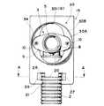
15は前記ジョイントエルボ3を固定する取付板であり、垂直壁15Aと水平壁15Bとを有して断面L型に折曲形成している。この取付板15の垂直壁15Aには、前記固定リング6より径大であり、かつ前記取付座9が挿通可能な縦長の長孔16と前記取付座9の透孔11と対応するねじ孔17とが形成され、一方、取付板15の水平壁15Bには釘やビスなどを通す透孔18が形成されている。また、垂直壁15Aの下端縁には前記鞘管2の突当片20を切り起し形するための左右一対の切欠部21が間隔をおいて形成されている。なお、前記突当片21は前記鞘管2の外周面に接するように外端縁を湾曲状に切り欠いて前記鞘管2と概ね同じ曲率を有する縁部21Aを形成している。
【0016】
24は前記鞘管2を固定するクランプであり、ばね鋼材を素材とする帯板を鞘管2の径サイズに応じて概ねU字状に形成してある。なお、クランプ24の両端には外側に折曲した係止片25が形成され、この係止片25を前記取付板15の切欠部21から通して前記鞘管2を前記取付板15に固定する。この場合、前記取付板15の切欠部21にはクランプ24の係止片25を嵌め入れる複数の切欠凹部26,27が段差状に切り欠いて連続的に形成されている。つまり、前記送水管1及びこの送水管1を外装する鞘管2は、流水量に応じて各種のサイズのものが使用され、当然、鞘管2を固定するクランプ24も鞘管2のサイズに応じて複数種用意され、そのクランプ24を固定する切欠凹部26,27を順次間隔が広がるように段差状に切り欠いて形成することにより、サイズが異なる複数種のクランプ24を同じ取付板15に固定することができる。
【0017】
30は前記取付板15の垂直壁15Aにスポット溶接などの適宜手段で固着される筒体であり、壁板31に形成する開口孔32に嵌め入れる環状周壁部30Aと前記取付板15に突き当てる底面部30Bとを有する有底筒型に形成してある。そして、筒体30の底面部30Bに前記長孔16と同一の長孔33が穿設され、この長孔33の内周面に前記ジョイントエルボ3の取付座9と嵌合するようにほぼU字型に切り欠いた位置決め凹部34を形成している。
【0018】
40は前記壁板31に形成する開口孔32の前面周縁部を覆う円板状の化粧キャップであり、前記ジョイントエルボ3と前記水栓7との間に介在している。この化粧キャップ40は、その中心に前記接続口5の貫通孔41が形成され、その貫通孔41の前面周縁に防水用のOリング41を装着している。
【0019】
次に以上のように構成される本実施例の取付手順について説明する。まず、ジョイントエルボ3の接続口4に送水管1を嵌め入れ、固定リング6によってジョイントエルボ3に送水管1を接続する。このようにして予めジョイントエルボ3と送水管1を組み付けた状態でジョイントエルボ3を取付板15に固定する場合、ジョイントエルボ3の取付座9を取付板15の長孔16,33に通して取付板15の前面側に取付座9を位置させる。そして、取付板15を90度回転させて取付座9の透孔11に挿通したねじ10をねじ孔17に螺着してジョイントエルボ3と取付板15とを固定する。なお、予めジョイントエルボ3と送水管1とをセットした後、ジョイントエルボ3を取付板15に固定した場合を例に説明したが、これ以外でもジョイントエルボ3を取付板15を固定してからジョイントエルボ3に送水管1を固定する方法もある。この場合、取付板15の前面側からジョイントエルボ3の固定リング6を取付板15の長孔16,33に通して取付板15とジョイントエルボ3とを固定し、この後、ジョイントエルボ3に送水管1を接続すればよい。つまり、予めジョイントエルボ3と送水管1を組み付けた状態でジョイントエルボ3を取付板15に固定するか、もしくは、ジョイントエルボ3を取付板15を固定してからジョイントエルボ3に送水管1を固定するかは現場で施工しやすい方法を選択的に採用すればよい。また、取付板15とジョイントエルボ3との固定に際して、ジョイントエルボ3の取付面となる取付板15の前面側には、取付座9と嵌合する位置決め凹部34が取付板15の前面側に固着する筒体30の底面部30Bに切欠形成してあるから、ジョイントエルボ3の取付座9と位置決め凹部34とを嵌合させてジョイントエルボ3と取付板15との位置合わせを簡単に行うことができるとともに、筒体30の中心にジョイントエルボ3の接続口5を同芯的に組み付けることができる。このようにして送水管1、ジョイントエルボ3、取付板15を組み付けた後、送水管1に外装する鞘管2をクランプ24によって取付板15に固定するが、この取付板15へのクランプ24の固定は、クランプ24をやや撓ませた状態で、その両端部を取付板15の切欠部21から挿入してクランプ24を上方側にスライドさせることにより、クランプ24の弾性復元力によって係止片25が切欠部21に形成する切欠凹部26,27のいずれかに弾発的に嵌入する。すなわち、図5に示すように、鞘管2の径が太い場合、当然、その鞘管2を固定するクランプ24の径も大型なものを使用するから、外側の切欠凹部27にクランプ24の係止片25を係止し、細い鞘管2を使用する場合、内側の切欠凹部26にクランプ24の係止片25を係止する。つまり、サイズの異なる複数種のクランプ24を取付板15に固定できる。こうしてクランプ24によって鞘管2を取付板15に固定した後、取付板15の前面に固着した筒部30の環状周壁部30Aを壁板31の開口孔32に嵌め入れた状態で取付板15の水平壁15Bに形成する透孔18にくぎ45などの止着具を通し、これを桟木46に固定する。そして、ジョイントエルボ3の接続口5に化粧キャップ40の貫通孔41を貫通させ、接続口5のねじ部8に水栓7をねじ込んで水栓7の施工作業が終了する。
【0020】
以上のように本実施例においては、L型に折曲した極めて簡単な構造の取付板15にジョイントエルボ3を固定でき、従来のようなジョイントエルボ3を内蔵するボックスを廃止できるからコストダウンが可能である。また、狭いボックスの内側でジョイントエルボ3の組み付ける必要もないから、作業的にもジョイントエルボ3を簡単に組み付けることができる。しかも、本実施例では、L型に折曲した取付板15に鞘管2をクランプ24により簡単に固定することができる。
【0021】
また、予め工場などにおいてジョイントエルボ3と送水管1及び鞘管2を取付板15に組み付けた状態でセットしてユニット化することも可能であり、このように予めユニット化すれば施工現場での作業は単に取付板15を桟木46に固定し、ジョイントエルボ3に水栓7を組み付けるだけで済むため、現場での施工作業を簡略化することができ、また、工期も短縮化できる。また、このような方法以外でも取付板15にジョイントエルボ3のみを組み付け、施工現場でジョイントエルボ3と送水管1を接続し、クランプ24によって取付板15に鞘管2を固定することも可能である。すなわち、予め各構成部品をユニット化するかあるいは施工現場で各構成部品を固定するかは、施工現場の状況に応じて任意に選択すればよい。
【0022】
また、取付板15にジョイントエルボ3を組み付ける際、ジョイントエルボ3の取付座9が取付板15の前面側に固着する筒体30の底部に切り欠いた位置決め凹部34に嵌まりジョイントエルボ3と取付板15との位置合わせが簡単であり、また、筒体30の中心にジョイントエルボ3の接続口5が同芯的に組み付けられる。しかも、本実施例では取付板15の前面に壁板31の開口孔32に嵌め入れる筒部30を固着しているから、壁板31の開口孔32の中心にジョイントエルボ3の接続口5を正確に位置合わせした状態でジョイントエルボ3を固定でき、施工に伴う各構成部品の位置決め作業が簡単で、効率的である。さらに、クランプ24による鞘管2の固定に際して、クランプ24を切欠部21から挿通し、この後、クランプ24を上方側にスライドさせてクランプ24自体の弾性復元力によって取付板15に鞘管2を簡単に固定できる。しかも、サイズの異なる複数種のクランプ24を固定できるよう、取付板15の切欠部21に幅の異なる二種類の切欠凹部26,27を形成してあるから、サイズの異なる複数種の鞘管2を固定する場合であっても、そのサイズに応じて複数種の取付板15を用意する必要がなく、取付板15を共通化できる。
【0023】
また、取付板15の前面側にジョイントエルボ3を固定したことにより、ジョイントエルボ3を固定するねじ10を緩めてジョイントエルボ3を取り外すことにより、ジョイントエルボ3に接続する送水管1が長孔16,33から引き出すことでき、送水管1の更新時にジョイントエルボ3と送水管1との着脱作業を迅速かつ容易に行うことができる。
【0024】
以上、本発明の一実施例を詳述したが本発明は前記実施例に限定されるものではなく、本発明の要旨の範囲内で種々の変形実施が可能である。例えば、取付板の形状などは適宜選定すればよいものであり、また、取付板に固着した筒体の底面部にジョイントエルボの取付座と嵌合する位置決め凹部を、U字型に切り欠いて形成した例を示したが、プレスなどにより、凹状に陥没させて位置決め凹部を形成してもよい。
【0025】
【発明の効果】
請求項1の発明によれば、両端部に送水管と水栓の接続口を有するジョイントエルボを設け、このジョイントエルボと前記送水管に外装する鞘管とを固定する断面L型の取付板を設け、この取付板を壁板の裏面側に固定して前記水栓の接続口を前記壁板の開口孔に臨ませるように前記ジョイントエルボを固定する水栓用ジョイントエルボの取付構造において、前記鞘管を固定するための可撓性を有するU字型のクランプを設け、このクランプの両端部に外側に屈曲する係止片を形成し、前記取付板の下端縁には、前記クランプの両端部を挿通する一対の切欠部を形成するとともに、その切欠部に前記係止片を係止する切欠凹部を形成して構成されるから、ジョイントエルボを内蔵するボックスを廃止してコストダウンが可能であり、また、狭いボックスの内側でジョイントエルボの組み付ける必要もないから、作業的にもジョイントエルボを簡単に組み付けることができるとともに、ジョイントエルボを組み付ける取付板に鞘管を簡単に固定することができる。
【0026】
請求項2の発明によれば、前記請求項1記載の水栓用ジョイントエルボの取付構造において、ジョイントエルボの水栓側接続口の外周に取付座を側方に向かって突設するとともに、前記取付板の前面側に前記取付座と嵌合する位置決め凹部を設けて構成されるから、ジョイントエルボと取付板との位置を正確に位置合せできる。
【0027】
請求項3の発明によれば、前記請求項1記載の水栓用ジョイントエルボの取付構造において、クランプを係止する切欠凹部を段差状に連続させて複数形成して構成されるから、サイズの異なる複数種の鞘管を固定する場合であても、そのサイズに応じて複数種の取付板を用意する必要がなく、取付板を共通化できる。
【図面の簡単な説明】
【図1】本発明の一実施例を示す分解斜視図である。
【図2】同上、水栓を取り付けた状態を示す全体断面図である。
【図3】同上、組み付け後の状態を示す取付板の正面図である。
【図4】同上、取付板の正面図である。
【図5】図3のA−A線断面図である。
【符号の説明】
1 送水管
2 鞘管
3 ジョイントエルボ
4,5 接続口
9 取付座
15 取付板
24 クランプ
25 係止片
26,27 切欠凹部
31 壁板
34 位置決め凹部[0001]
TECHNICAL FIELD OF THE INVENTION
The present invention relates to a faucet joint elbow mounting structure for fixing a faucet to a wall surface of a bathroom, a toilet, a washroom, or the like in a building.
[0002]
Technical Problems to be Solved by the Invention
2. Description of the Related Art In recent years, a construction method called a sheath pipe header construction method has been widely known as a plumbing method for water supply and hot water supply in an apartment house or a high-rise building. In this sheath pipe header method, a synthetic resin water pipe is branched from a header connected to a water supply device, the water pipe is externally covered with a flexible sheath pipe and crawled under the floor or under the ceiling, and the sheath pipe is further filled with water. It is arranged on the back side of the wall plate to draw it to the mounting position of the plug and fixed so that the joint elbow connected to the water pipe faces the opening hole formed in the wall plate, and then the water tap is connected to the joint elbow I am trying to do it.
[0003]
As a connection structure between a water pipe and a faucet in such a sheath pipe header method, for example, JP-A-4-20618 and JP-A-5-79072 disclose an L-shaped joint elbow connected to a water pipe. A box type joint is disclosed in which the box is fixed to the inside of a box, and the box is fixed to the back side of the wall plate in a state where the end of the sheath tube provided on the water pipe is fixed to the bottom side of the box. Have been.
[0004]
Such a box-type joint has a complicated structure and is costly, and it is necessary to connect the joint elbow and the water pipe in a narrow space inside the box. , And the workability was inferior.
[0005]
For this reason, a box for accommodating the joint elbow is abolished, and a support for the joint elbow in which the joint elbow is simply fixed to a support which is bent into an L shape is disclosed in Japanese Utility Model Laid-Open No. 5-71574. I have. However, since this support fixes only the joint elbow, there is no means for fixing the sheath pipe that protects the water pipe, so when using the sheath pipe header method described above, it is necessary to separately provide a means for fixing the sheath pipe. There is a complicated structure. In addition, water supply pipes for water supply and hot water supply in high-rise buildings, etc., use multiple types of water supply pipes of different sizes according to the flow rate, and the sheath pipe that is external to the water supply pipe is inevitably also the size of the water supply pipe. Accordingly, since a plurality of types are used, it is necessary to facilitate a number of types of supports according to the size, and there is a problem that a manufacturing process is complicated and parts management is complicated.
[0006]
The present invention is intended to solve such a problem, and can easily fix a joint elbow and a sheath tube to an L-shaped attachment plate having a simple structure, and can attach a sheath tube having a different size to a single attachment plate. An object of the present invention is to provide a mounting structure of a faucet joint elbow that can be fixed to a plate.
[0007]
[Means for Solving the Problems]
In order to achieve the above object, the invention according to claim 1 is provided with a joint elbow having a connection port for a water pipe and a faucet at both ends, and a cross section for fixing the joint elbow and a sheath pipe to be externally provided to the water pipe. A faucet joint elbow for providing an L-shaped mounting plate, fixing the mounting plate to the back side of the wall plate, and fixing the joint elbow so that the connection port of the faucet faces the opening hole of the wall plate. In the mounting structure of (1), a flexible U-shaped clamp for fixing the sheath tube is provided, and locking pieces bent outward at both ends of the clamp are formed. Is formed by forming a pair of notches through which both ends of the clamp are inserted, and a notch recess for locking the locking piece in the notch.
[0008]
According to the above configuration, since the joint elbow is fixed to the mounting plate bent into an L-shape, the construction is easy, and the connection work between the joint elbow and the water pipe can be easily performed. Moreover, the sheath tube can be easily fixed to the mounting plate simply by inserting both ends of the clamp into the notch of the mounting plate and fitting the locking piece of the clamp into the notch recess of the mounting plate by the elastic restoring force of the clamp. it can.
[0009]
According to a second aspect of the present invention, in the mounting structure for a faucet joint elbow according to the first aspect, a mounting seat protrudes laterally on an outer periphery of a faucet side connection port of the joint elbow, and the mounting plate is provided. Is provided with a positioning concave portion which is fitted to the mounting seat on the front side.
[0010]
According to the above configuration, when the mounting plate and the joint are fixed, the mounting seat of the elbow joint elbow fits into the positioning recess formed on the front side of the mounting plate, and the alignment between the joint elbow and the mounting plate can be accurately fixed. .
[0011]
According to a third aspect of the present invention, in the mounting structure for a faucet joint elbow according to the first aspect, a plurality of cutout recesses for engaging the clamps are formed continuously in a stepped manner.
[0012]
According to the above configuration, even when a plurality of types of sheath tubes having different sizes are fixed, there is no need to prepare a plurality of types of mounting plates according to the sizes, and the mounting plates can be shared.
[0013]
DETAILED DESCRIPTION OF THE INVENTION
One embodiment of a mounting structure of a faucet joint elbow according to the present invention will be described with reference to FIGS. In FIG. 1, reference numeral 1 denotes a water pipe made of, for example, bolybdenum,
[0014]
The
[0015]
[0016]
[0017]
[0018]
[0019]
Next, the mounting procedure of the present embodiment configured as described above will be described. First, the water pipe 1 is fitted into the connection port 4 of the
[0020]
As described above, in the present embodiment, the
[0021]
Further, it is also possible to set the
[0022]
When assembling the
[0023]
Further, since the
[0024]
As mentioned above, although one Example of this invention was described in detail, this invention is not limited to the said Example, A various deformation | transformation implementation is possible within the range of the gist of this invention. For example, the shape and the like of the mounting plate may be appropriately selected, and a positioning recess for fitting with the mounting seat of the joint elbow is cut out in a U-shape on the bottom surface of the cylindrical body fixed to the mounting plate. Although an example in which the positioning recess is formed is shown, the positioning recess may be formed by being depressed into a concave shape by pressing or the like.
[0025]
【The invention's effect】
According to the invention of claim 1, a joint elbow having a connection port for a water pipe and a faucet is provided at both ends, and an L-shaped mounting plate for fixing the joint elbow and a sheath pipe to be fitted to the water pipe is provided. In the mounting structure of a faucet joint elbow, the mounting plate is fixed to the back surface side of the wall plate and the joint elbow is fixed so that the connection port of the faucet faces the opening hole of the wall plate. A flexible U-shaped clamp for fixing the sheath tube is provided, and a locking piece that bends outward is formed at both ends of the clamp. At both ends of the mounting plate, both ends of the clamp are provided. It is formed by forming a pair of notches through which the parts are inserted, and by forming a notch concave portion that locks the locking piece in the notch, eliminating the box with a built-in joint elbow and reducing costs And narrow Since there is no need to assemble the joint elbow inside the box, it is possible to it is possible to assemble easily joint elbow to work, the easily fix the sheath tube to the mounting plate to assemble the joint elbow.
[0026]
According to the invention of
[0027]
According to the third aspect of the present invention, in the mounting structure of the faucet joint elbow according to the first aspect, a plurality of cutout recesses for locking the clamp are formed continuously in a step-like manner. Even when a plurality of different types of sheath tubes are fixed, there is no need to prepare a plurality of types of mounting plates according to their sizes, and the mounting plates can be shared.
[Brief description of the drawings]
FIG. 1 is an exploded perspective view showing one embodiment of the present invention.
FIG. 2 is an overall sectional view showing a state where a faucet is attached.
FIG. 3 is a front view of the mounting plate showing a state after assembly.
FIG. 4 is a front view of the same mounting plate.
FIG. 5 is a sectional view taken along line AA of FIG. 3;
[Explanation of symbols]
DESCRIPTION OF SYMBOLS 1
Claims (3)
Translated fromJapanesePriority Applications (1)
| Application Number | Priority Date | Filing Date | Title |
|---|---|---|---|
| JP19101696AJP3570097B2 (en) | 1996-07-19 | 1996-07-19 | Mounting structure of the faucet joint elbow |
Applications Claiming Priority (1)
| Application Number | Priority Date | Filing Date | Title |
|---|---|---|---|
| JP19101696AJP3570097B2 (en) | 1996-07-19 | 1996-07-19 | Mounting structure of the faucet joint elbow |
Publications (2)
| Publication Number | Publication Date |
|---|---|
| JPH1037259A JPH1037259A (en) | 1998-02-10 |
| JP3570097B2true JP3570097B2 (en) | 2004-09-29 |
Family
ID=16267488
Family Applications (1)
| Application Number | Title | Priority Date | Filing Date |
|---|---|---|---|
| JP19101696AExpired - Fee RelatedJP3570097B2 (en) | 1996-07-19 | 1996-07-19 | Mounting structure of the faucet joint elbow |
Country Status (1)
| Country | Link |
|---|---|
| JP (1) | JP3570097B2 (en) |
Families Citing this family (4)
| Publication number | Priority date | Publication date | Assignee | Title |
|---|---|---|---|---|
| JP4512430B2 (en)* | 2004-06-25 | 2010-07-28 | 大和ハウス工業株式会社 | Water supply / drainage unit for washing machine and vanity |
| JP6499463B2 (en)* | 2015-02-03 | 2019-04-10 | 大阪瓦斯株式会社 | Stopper fixing structure |
| KR102570031B1 (en)* | 2021-09-08 | 2023-08-23 | 유새롬 | Fixation structure of fauset connectors and fauset apparatus |
| KR102570032B1 (en)* | 2021-09-08 | 2023-08-23 | 유새롬 | Fixation and separation method for fauset connectors |
- 1996
- 1996-07-19JPJP19101696Apatent/JP3570097B2/ennot_activeExpired - Fee Related
Also Published As
| Publication number | Publication date |
|---|---|
| JPH1037259A (en) | 1998-02-10 |
Similar Documents
| Publication | Publication Date | Title |
|---|---|---|
| CA2541309C (en) | Plaster guard for a wall mounted faucet valve assembly | |
| US5060892A (en) | Plumbing hanger bracket assembly | |
| US6422520B1 (en) | Universal mounting bracket | |
| JP3570097B2 (en) | Mounting structure of the faucet joint elbow | |
| US7039966B1 (en) | Detachable sink shelf plate | |
| US7426937B2 (en) | Bracket system for securing single-lever-valves and associated water pipework to a support board located inside a wall | |
| JP6840628B2 (en) | Installation structure of joint accommodating box, fitting accommodating box and piping protection cover, and mixing faucet | |
| JP4664758B2 (en) | Back piping fitting mounting structure | |
| JP5352126B2 (en) | Water supply piping structure | |
| JPH08226560A (en) | Installation structure from plate type member upper surface of faucet | |
| JP5209372B2 (en) | Pipe fitting | |
| US7490376B2 (en) | Drain outlet with integral clamp for use with a plumbing fixture | |
| JPH0640689Y2 (en) | Mounting device for faucets, etc. | |
| JPH08284220A (en) | Faucet joint and on-wall mounting method therefor | |
| JPH1193229A (en) | Installing structure of faucet | |
| JP3887111B2 (en) | Water faucet installation structure | |
| JPH039187A (en) | Fixing structure for elbow into piping box | |
| JPH09328790A (en) | Faucet installation structure | |
| JPH0650593Y2 (en) | Fluid piping box | |
| CN112096962B (en) | Industrial pipe fitting adapter kit and method | |
| JPH078609Y2 (en) | Cover for exposed water tap fitting | |
| JPH0656030B2 (en) | Relay connector for fluid pipes | |
| JP2990582B2 (en) | Faucet installation structure with bent piping | |
| JPH0736234Y2 (en) | Protective cover connection | |
| JP2645512B2 (en) | Flexible tube terminal holder |
Legal Events
| Date | Code | Title | Description |
|---|---|---|---|
| A977 | Report on retrieval | Free format text:JAPANESE INTERMEDIATE CODE: A971007 Effective date:20040423 | |
| TRDD | Decision of grant or rejection written | ||
| A01 | Written decision to grant a patent or to grant a registration (utility model) | Free format text:JAPANESE INTERMEDIATE CODE: A01 Effective date:20040601 | |
| A61 | First payment of annual fees (during grant procedure) | Free format text:JAPANESE INTERMEDIATE CODE: A61 Effective date:20040614 | |
| R150 | Certificate of patent or registration of utility model | Free format text:JAPANESE INTERMEDIATE CODE: R150 | |
| FPAY | Renewal fee payment (event date is renewal date of database) | Free format text:PAYMENT UNTIL: 20080702 Year of fee payment:4 | |
| FPAY | Renewal fee payment (event date is renewal date of database) | Free format text:PAYMENT UNTIL: 20090702 Year of fee payment:5 | |
| FPAY | Renewal fee payment (event date is renewal date of database) | Free format text:PAYMENT UNTIL: 20100702 Year of fee payment:6 | |
| FPAY | Renewal fee payment (event date is renewal date of database) | Free format text:PAYMENT UNTIL: 20110702 Year of fee payment:7 | |
| FPAY | Renewal fee payment (event date is renewal date of database) | Free format text:PAYMENT UNTIL: 20110702 Year of fee payment:7 | |
| FPAY | Renewal fee payment (event date is renewal date of database) | Free format text:PAYMENT UNTIL: 20120702 Year of fee payment:8 | |
| LAPS | Cancellation because of no payment of annual fees |