JP3568328B2 - Clothes dryer - Google Patents
Clothes dryerDownload PDFInfo
- Publication number
- JP3568328B2 JP3568328B2JP21941896AJP21941896AJP3568328B2JP 3568328 B2JP3568328 B2JP 3568328B2JP 21941896 AJP21941896 AJP 21941896AJP 21941896 AJP21941896 AJP 21941896AJP 3568328 B2JP3568328 B2JP 3568328B2
- Authority
- JP
- Japan
- Prior art keywords
- motor
- predetermined
- clothes dryer
- abnormality
- rotation
- Prior art date
- Legal status (The legal status is an assumption and is not a legal conclusion. Google has not performed a legal analysis and makes no representation as to the accuracy of the status listed.)
- Expired - Fee Related
Links
- 230000005856abnormalityEffects0.000claimsdescription59
- 238000010981drying operationMethods0.000claimsdescription49
- 238000001514detection methodMethods0.000claimsdescription43
- 238000000034methodMethods0.000description28
- 230000008569processEffects0.000description28
- 238000001035dryingMethods0.000description27
- 238000010438heat treatmentMethods0.000description8
- 238000001816coolingMethods0.000description7
- 238000005192partitionMethods0.000description6
- 230000002159abnormal effectEffects0.000description5
- 230000007246mechanismEffects0.000description5
- 230000000052comparative effectEffects0.000description4
- 230000003111delayed effectEffects0.000description3
- 238000010586diagramMethods0.000description3
- 230000005540biological transmissionEffects0.000description2
- 238000004891communicationMethods0.000description2
- 239000000835fiberSubstances0.000description2
- 238000012986modificationMethods0.000description2
- 230000004048modificationEffects0.000description2
- 230000002093peripheral effectEffects0.000description2
- 230000009467reductionEffects0.000description2
- 230000001360synchronised effectEffects0.000description2
- 229920003002synthetic resinPolymers0.000description2
- 239000000057synthetic resinSubstances0.000description2
- XLYOFNOQVPJJNP-UHFFFAOYSA-NwaterSubstancesOXLYOFNOQVPJJNP-UHFFFAOYSA-N0.000description2
- 230000002238attenuated effectEffects0.000description1
- 230000004397blinkingEffects0.000description1
- 230000008859changeEffects0.000description1
- 230000003247decreasing effectEffects0.000description1
- 238000007599dischargingMethods0.000description1
- 238000002845discolorationMethods0.000description1
- 238000006073displacement reactionMethods0.000description1
- 230000000694effectsEffects0.000description1
- 239000002184metalSubstances0.000description1
- 238000007789sealingMethods0.000description1
- 239000004065semiconductorSubstances0.000description1
- 238000000926separation methodMethods0.000description1
- 239000000758substrateSubstances0.000description1
Images


Classifications
- D—TEXTILES; PAPER
- D06—TREATMENT OF TEXTILES OR THE LIKE; LAUNDERING; FLEXIBLE MATERIALS NOT OTHERWISE PROVIDED FOR
- D06F—LAUNDERING, DRYING, IRONING, PRESSING OR FOLDING TEXTILE ARTICLES
- D06F58/00—Domestic laundry dryers
- D06F58/30—Drying processes
- D—TEXTILES; PAPER
- D06—TREATMENT OF TEXTILES OR THE LIKE; LAUNDERING; FLEXIBLE MATERIALS NOT OTHERWISE PROVIDED FOR
- D06F—LAUNDERING, DRYING, IRONING, PRESSING OR FOLDING TEXTILE ARTICLES
- D06F58/00—Domestic laundry dryers
- D06F58/32—Control of operations performed in domestic laundry dryers
- D06F58/34—Control of operations performed in domestic laundry dryers characterised by the purpose or target of the control
- D06F58/50—Responding to irregular working conditions, e.g. malfunctioning of blowers
- D—TEXTILES; PAPER
- D06—TREATMENT OF TEXTILES OR THE LIKE; LAUNDERING; FLEXIBLE MATERIALS NOT OTHERWISE PROVIDED FOR
- D06F—LAUNDERING, DRYING, IRONING, PRESSING OR FOLDING TEXTILE ARTICLES
- D06F2101/00—User input for the control of domestic laundry washing machines, washer-dryers or laundry dryers
- D06F2101/20—Operation modes, e.g. delicate laundry washing programs, service modes or refreshment cycles
- D—TEXTILES; PAPER
- D06—TREATMENT OF TEXTILES OR THE LIKE; LAUNDERING; FLEXIBLE MATERIALS NOT OTHERWISE PROVIDED FOR
- D06F—LAUNDERING, DRYING, IRONING, PRESSING OR FOLDING TEXTILE ARTICLES
- D06F2103/00—Parameters monitored or detected for the control of domestic laundry washing machines, washer-dryers or laundry dryers
- D06F2103/24—Spin speed; Drum movements
- D—TEXTILES; PAPER
- D06—TREATMENT OF TEXTILES OR THE LIKE; LAUNDERING; FLEXIBLE MATERIALS NOT OTHERWISE PROVIDED FOR
- D06F—LAUNDERING, DRYING, IRONING, PRESSING OR FOLDING TEXTILE ARTICLES
- D06F2103/00—Parameters monitored or detected for the control of domestic laundry washing machines, washer-dryers or laundry dryers
- D06F2103/28—Air properties
- D06F2103/32—Temperature
- D—TEXTILES; PAPER
- D06—TREATMENT OF TEXTILES OR THE LIKE; LAUNDERING; FLEXIBLE MATERIALS NOT OTHERWISE PROVIDED FOR
- D06F—LAUNDERING, DRYING, IRONING, PRESSING OR FOLDING TEXTILE ARTICLES
- D06F2103/00—Parameters monitored or detected for the control of domestic laundry washing machines, washer-dryers or laundry dryers
- D06F2103/28—Air properties
- D06F2103/34—Humidity
- D—TEXTILES; PAPER
- D06—TREATMENT OF TEXTILES OR THE LIKE; LAUNDERING; FLEXIBLE MATERIALS NOT OTHERWISE PROVIDED FOR
- D06F—LAUNDERING, DRYING, IRONING, PRESSING OR FOLDING TEXTILE ARTICLES
- D06F2103/00—Parameters monitored or detected for the control of domestic laundry washing machines, washer-dryers or laundry dryers
- D06F2103/38—Time, e.g. duration
- D—TEXTILES; PAPER
- D06—TREATMENT OF TEXTILES OR THE LIKE; LAUNDERING; FLEXIBLE MATERIALS NOT OTHERWISE PROVIDED FOR
- D06F—LAUNDERING, DRYING, IRONING, PRESSING OR FOLDING TEXTILE ARTICLES
- D06F2103/00—Parameters monitored or detected for the control of domestic laundry washing machines, washer-dryers or laundry dryers
- D06F2103/40—Opening or locking status of doors
- D—TEXTILES; PAPER
- D06—TREATMENT OF TEXTILES OR THE LIKE; LAUNDERING; FLEXIBLE MATERIALS NOT OTHERWISE PROVIDED FOR
- D06F—LAUNDERING, DRYING, IRONING, PRESSING OR FOLDING TEXTILE ARTICLES
- D06F2103/00—Parameters monitored or detected for the control of domestic laundry washing machines, washer-dryers or laundry dryers
- D06F2103/44—Current or voltage
- D06F2103/46—Current or voltage of the motor driving the drum
- D—TEXTILES; PAPER
- D06—TREATMENT OF TEXTILES OR THE LIKE; LAUNDERING; FLEXIBLE MATERIALS NOT OTHERWISE PROVIDED FOR
- D06F—LAUNDERING, DRYING, IRONING, PRESSING OR FOLDING TEXTILE ARTICLES
- D06F2105/00—Systems or parameters controlled or affected by the control systems of washing machines, washer-dryers or laundry dryers
- D06F2105/46—Drum speed; Actuation of motors, e.g. starting or interrupting
- D06F2105/48—Drum speed
- D—TEXTILES; PAPER
- D06—TREATMENT OF TEXTILES OR THE LIKE; LAUNDERING; FLEXIBLE MATERIALS NOT OTHERWISE PROVIDED FOR
- D06F—LAUNDERING, DRYING, IRONING, PRESSING OR FOLDING TEXTILE ARTICLES
- D06F2105/00—Systems or parameters controlled or affected by the control systems of washing machines, washer-dryers or laundry dryers
- D06F2105/58—Indications or alarms to the control system or to the user
- D06F2105/60—Audible signals
- D—TEXTILES; PAPER
- D06—TREATMENT OF TEXTILES OR THE LIKE; LAUNDERING; FLEXIBLE MATERIALS NOT OTHERWISE PROVIDED FOR
- D06F—LAUNDERING, DRYING, IRONING, PRESSING OR FOLDING TEXTILE ARTICLES
- D06F2105/00—Systems or parameters controlled or affected by the control systems of washing machines, washer-dryers or laundry dryers
- D06F2105/62—Stopping or disabling machine operation
- D—TEXTILES; PAPER
- D06—TREATMENT OF TEXTILES OR THE LIKE; LAUNDERING; FLEXIBLE MATERIALS NOT OTHERWISE PROVIDED FOR
- D06F—LAUNDERING, DRYING, IRONING, PRESSING OR FOLDING TEXTILE ARTICLES
- D06F34/00—Details of control systems for washing machines, washer-dryers or laundry dryers
- D06F34/10—Power supply arrangements, e.g. stand-by circuits
- D—TEXTILES; PAPER
- D06—TREATMENT OF TEXTILES OR THE LIKE; LAUNDERING; FLEXIBLE MATERIALS NOT OTHERWISE PROVIDED FOR
- D06F—LAUNDERING, DRYING, IRONING, PRESSING OR FOLDING TEXTILE ARTICLES
- D06F34/00—Details of control systems for washing machines, washer-dryers or laundry dryers
- D06F34/28—Arrangements for program selection, e.g. control panels therefor; Arrangements for indicating program parameters, e.g. the selected program or its progress
Landscapes
- Engineering & Computer Science (AREA)
- Textile Engineering (AREA)
- Control Of Washing Machine And Dryer (AREA)
- Detail Structures Of Washing Machines And Dryers (AREA)
Description
Translated fromJapanese【0001】
【発明の属する技術分野】
本発明は、衣類乾燥機に関する。
【0002】
【従来の技術】
家庭用の衣類乾燥機は、湿った衣類を収容したドラム内に乾燥した熱風を供給し、衣類から蒸発した水分を含む湿った熱風を冷却することにより除湿し、乾燥させた空気をヒータにて再加熱してドラムへ循環する構成となっている。ドラムは水平軸を中心にゆっくりと回転され、これによりドラム内の衣類は攪拌されてむらのない乾燥が実行される。
【0003】
一般に、このような衣類乾燥機では、循環風を発生させるためのファンとドラムとをそれぞれ回転させるために唯一のモータが設けられ、そのモータの回転軸からプーリ、Vベルト等の伝達機構を介してファン及びドラムをそれぞれ所定の回転速度にて回転駆動するようにしている。ドラム側の回転伝達機構は、モータの回転軸に取り付けられたプーリ、そのプーリと円筒形状のドラムの外周面とに巻掛けられたVベルト、及び、Vベルトに張力を与えるテンション機構から成っている。
【0004】
【発明が解決しようとする課題】
上記衣類乾燥機において、Vベルトが切れたり外れたり、或いはテンション機構が故障してVベルトに張力を与えられなくなった場合には、ドラムは正常に回転しないか又は停止することになる。このような場合、ドラム内への熱風の吹出口近傍に溜まった衣類に熱風が集中的に吹き掛かるため、その衣類は異常に高温になり、繊維の種類によっては変色や焦げが発生する恐れがある。
【0005】
このような異常状態を検知するため、例えば、特開昭60−48795号公報に記載の発明ではテンション機構のスプリングの変位を検知するようにしている。しかしながら、そのような機械的な構造により異常検知を行なうと、特別な機械部品が必要となりコストが高くなると共に、組立にも手間を要してしまう。
【0006】
本発明は上記問題を解決するために成されたもので、その目的とするところは、ベルト切れや外れ等のベルト異常検知を簡単な構成にて確実に行なうことによりドラム内の衣類の異常加熱を防止することができる衣類乾燥機を提供することにある。
【0007】
【課題を解決するための手段】
上記課題を解決するために成された本発明の第1の衣類乾燥機は、衣類を収容したドラムにヒータにて加熱した熱風を送り込み、該ドラム内を通過した空気を冷却して除湿した後に該乾燥風を循環させる衣類乾燥機であって、モータの回転駆動力をベルトを介してドラムへ伝達する衣類乾燥機において、
a)モータの回転数を検出する回転数検出手段と、
b)運転初期において、前記ヒータへの通電を開始する前に、第1の所定時間モータを駆動した後に第2の所定時間モータへの通電を停止する駆動制御手段と、
c)前記第2の所定時間内に前記回転数検出手段により検出したモータの回転数を計数する計数手段と、
d)該計数手段の計数値が所定の値を越えている場合に運転を停止する異常検知手段と、
を備え、
前記計数手段の計数値が所定の値以下である場合には、前記モータの駆動を再開すると共に前記ヒータの通電を開始させることを特徴としている。
【0008】
本発明の第2の衣類乾燥機は、上記第1の衣類乾燥機において、前記駆動制御手段は所定の乾燥運転時間が経過した後にも第3の所定時間モータへの通電を停止し、前記計数手段は第3の所定時間内に前記回転数検出手段により検出したモータの回転数を計数し、前記異常検知手段は該計数手段の計数値が所定の値を越えている場合に運転を停止することを特徴としている。ここで、第3の所定時間と第2の所定時間とを同一にすると構成を簡単にすることができる。
【0009】
本発明の第3の衣類乾燥機は、上記第2の衣類乾燥機において、所定の乾燥運転時間が経過した後に異常検知を行なう際に、モータへの通電を停止する前にモータに対する負荷を推定する負荷推定手段を備え、所定以下の負荷量であると判断した場合にモータへの通電を停止して異常検知を行なうことを特徴としている。
【0010】
本発明の第4の衣類乾燥機は、上記第3の衣類乾燥機において、特に位相制御によりモータの回転を制御する場合に、前記負荷推定手段はモータが所定回転数にて回転するように制御しているときのモータに供給される電力量に対応した位相制御角を判定する構成とすることを特徴としている。
【0011】
本発明の第5の衣類乾燥機は、上記第3の衣類乾燥機において、所定の乾燥運転時間が経過した後の異常検知にて異常が検知されない場合に、第4の所定時間モータを駆動した後に第3の所定時間モータへの通電を停止し、第3の所定時間内に回転数検出手段により検出したモータの回転数を計数した値を所定の値と比較する、という異常検知動作を複数回繰り返し実行し、いずれにおいても異常が検知されないときには乾燥運転を続行する構成とすることを特徴としている。ここで、第4の所定時間と第1の所定時間とを同一にすると構成を簡単にすることができる。
【0012】
【発明の実施の形態】
第1の衣類乾燥機において、駆動制御手段は、乾燥運転の開始後、ヒータへの通電を開始する前に、モータが所定の定常回転速度まで上昇するようにモータに駆動電流を供給し、第1の所定時間が経過したならば駆動を一旦停止する。ここで、第1の所定時間は、モータがほぼ所定の定常回転速度に到達するに充分な時間に予め定めておく。駆動制御手段がモータの駆動を停止すると、モータはその駆動停止直前の回転の惰性により回転し続ける。惰性回転中、モータに対する負荷が大きいとその回転速度は急速に減速するが、モータに対する負荷が小さいと回転速度の減速の度合は小さく比較的高い回転速度が暫時維持される。計数手段は、モータ駆動が停止されている第2の所定時間の間に回転数検出手段から得られるモータの回転に同期したパルス信号を計数することにより、惰性回転中のモータの回転状況を把握する。モータがベルトを介して正常な状態でドラムを回転駆動していればモータには適度な負荷が加わっている筈であるから、惰性回転中にモータの回転速度は確実に減速する。一方、ベルト切れや外れ等によりドラムを回転駆動していない場合には、惰性回転中にモータの回転速度はあまり下がらないので、異常検知手段は、モータ回転の計数値を所定値と比較することにより異常を検知し、異常が検知されたならば乾燥運転を停止させる。一方、ドラムの回転駆動は正常であると判断すると、モータの駆動を再開すると共にヒータへの通電を開始させる。
【0013】
上記の異常検知動作は乾燥運転の初期に行なわれるが、乾燥運転中にベルト切れや外れ等の異常が発生した場合には、その乾燥運転のサイクル中に異常を検知することが望ましい。そこで、第2の衣類乾燥機においては、駆動制御手段は、所定の乾燥運転時間が経過した後にも第3の所定時間モータの駆動を停止することによりモータを惰性にて回転させる。そして、計数手段は、モータの駆動が停止されている第3の所定時間の間に回転数検出手段から得られるモータの回転に同期したパルス信号を計数する。異常検知手段は、この計数値が所定の値を越えている場合には乾燥運転中に異常が発生したと判断し、乾燥運転を停止する。
【0014】
なお、上記のように乾燥運転中にモータの駆動を一旦停止することは乾燥性能を落とすことになるから、異常発生の可能性がないか又は極めて小さい場合には避けることが望ましい。そこで、第3の衣類乾燥機では、所定の乾燥運転時間が経過した後に異常検知を行なう際、まずモータの駆動を停止することなく異常発生の有無を判断するために、負荷推定手段がモータに対する負荷を検出し、所定以下の負荷である場合にはベルト切れや外れ等の異常が発生している可能性が高いと判断する。そして、この場合にのみ、駆動制御手段はモータの駆動を停止してモータを惰性にて回転させ、モータ回転数による異常検知を実行する。
【0015】
ところで、位相制御によりモータの回転制御を行なう場合、通常、交流電源のゼロクロス点から或る時間遅延した時点でモータON信号を出力してモータ電流をON/OFFするトライアック等を導通させ、モータへの通電を開始する。そして、ゼロクロス点を0°としたモータON時点の相対位相角(0°〜180°の範囲内)を調整することによりモータへ供給する電力量を変化させてモータ回転を制御する。同一回転速度にてモータを回転させるように制御する際、モータに対する負荷が大きいほどより大きなトルクが必要となるから、より大きな電力をモータに供給する必要がある。そこで、第4の衣類乾燥機においては、例えば、ゼロクロス点からモータON時点までの角度である導通角、或いは、モータON時点から所定の相対位相角位置までの角度である通電角の大きさによりモータの負荷を推定する。例えば、負荷量が小さいほど通電角は小さいから、通電角を所定の角度と比較し、所定の角度以下である場合に負荷量が異常に小さくベルト切れや外れの可能性があると判断する。
【0016】
また、所定の乾燥運転時間が経過した後の異常検知をより確実に行なうためには、第5の衣類乾燥機のように、1回のみでなく同じ異常検知動作を複数回繰り返して行ない、いずれにおいても異常が認められない場合に引き続き乾燥運転を行なうようにすると良い。勿論、繰り返しの回数を多くすれば異常検知の確実性は増すが、ドラムの回転速度が頻繁に下がり、乾燥性能が劣化するのみならず使用者に対して与える印象も良くない。そこで、異常検知の繰り返し回数は3回程度にすると適当である。
【0017】
【発明の効果】
本発明に係る第1の衣類乾燥機によれば、乾燥運転開始直後、ドラムが正常に回転しているか否かが検知され、ドラムの回転が正常でない場合には、乾燥運転が停止される。このため、乾燥運転前にVベルト切れや外れ等の異常が発生したことを確実に検知することができるため、ドラム内の衣類の異常加熱を未然に防ぐことができる。
【0018】
また、第2の衣類乾燥機によれば、所定の乾燥運転時間が経過した後にも、ドラムが正常に回転しているか否かが検知され、ドラムの回転が正常でない場合には、その時点で乾燥運転が停止される。このため、乾燥運転中にVベルト切れや外れ等の異常が発生したことを確実に且つ迅速に検知することができるため、ドラム内の衣類の異常加熱を防ぐことができる。
【0019】
また、第3及び第4の衣類乾燥機によれば、所定の乾燥運転時間が経過した後に異常検知を行なう際にドラムの回転を落とさずにモータの負荷を推定し、モータの負荷が軽くVベルト切れの可能性が高い場合にドラムの回転速度を落とし異常検知がなされる。このため、Vベルト切れの可能性が殆どないにも拘らず異常検知のためにドラムの回転速度が下がるということがなくなるため、乾燥性能が維持されると共に使用者に対する印象を低下させることもない。
【0020】
更に、第5の衣類乾燥機によれば、所定の乾燥運転時間が経過した後に異常検知が複数回繰り返して行なわれるので、検知見逃しが格段に少なくなり信頼性が増す。
【0021】
【実施例】
以下、本発明による衣類乾燥機の一実施例を図1〜図8に基づいて説明する。まず、この衣類乾燥機の全体構成を図1の側面縦断面図を参照して説明する。衣類乾燥機1の機枠2の前面中央には衣類投入口3が設けられ、その開口はドア4により開閉される。機枠2の背面には後面板5が止着され、後面板5の略中央には外部空気の吸気口6が形成されている。一方、機枠2の下面には空気の排気口7が形成されている。機枠2内において、衣類投入口3を取り囲むように環状の板金製のドラム支持板8が取り付けられ、また後部には後面板5と所定間隔を保って横方向に支持板9が架設されている。この支持板9には一部を切り欠いたファンケーシング10が固定されており、これにより機枠2内はファン室11と乾燥室12とに区画されている。
【0022】
乾燥室12内には水平軸型のドラム13が、前面開口を衣類投入口3に対向させた状態でドラム支持板8にフェルト等を介して支持され、後面側は主軸14により回転自在に軸支されている。ドラム13の背面にはリントフィルタ16に被覆された空気出口15が形成される一方、前面のドラム支持板8の下部には空気取入口17が形成されている。支持板9には乾燥室12とファン室11とを連通する連通口18が形成され、空気出口15からの空気流が確実に連通口18に至るようにシール部材19がドラム13と支持板9との間に取り付けられている。
【0023】
ファン室11内においては、主軸14に円板状の合成樹脂製の両面ファン20が固着され、乾燥室12側に位置する循環ファン20aと後面板5側に位置する冷却ファン20bとがそれぞれ放射状に表裏一体に形成されている。ファンケーシング10内には両面ファン20を囲むように隔壁21が設けられ、この隔壁21の略中央の円形開口に両面ファン20を収容することにより、この両面ファン20と隔壁21とが相まってファン室11内を乾燥風路22と冷却風路23とに区画している。両面ファン20の周縁には乾燥風路22へ向けて開口する同心状の回転溝が一体形成され、一方、隔壁21の内周縁には冷却風路23へ向けて開口する同心状の固定溝が形成されており、両面ファン20の回転溝と隔壁21の固定溝とは相互に非接触状態で遊嵌されている。すなわち、両面ファン20の回転溝と隔壁21の固定溝とはラビリンス結合を成している。このため、乾燥風路22と冷却風路23との間は空気の交換ができないようになっている。
【0024】
乾燥風路22の下部とドラム支持板8に形成されている空気取入口17とは乾燥ダクト24により連結されており、その内部の空気取入口17付近には加熱ヒータ25が配置されている。この加熱ヒータ25は、例えばハニカム形状の正特性サーミスタで構成されている。乾燥ダクト24の最下部には、乾燥ダクト24内に凝縮した除湿水を機外に排出するための排水口26が設けられている。
【0025】
機枠2内の底部にはモータ27が配置されている。モータ27は、ドラム13の外周面に巻掛けられたVベルト32にプーリ31を介して回転力を与える一方、プーリ28、ファンベルト29を介して冷却ファン20bの中央に形成されたプーリ30に回転力を与えている。また、Vベルト32のスリップを防止するために、ドラム回転時にアイドラプーリ33がVベルト32に適当な張力を加える。プーリ28にはモータ27の回転数を検出するための回転センサ34が取り付けられている。
【0026】
而して、乾燥運転時には、モータ27の回転駆動力により、ドラム13が低速で、両面ファン20は高速でそれぞれ回転され、同時に加熱ヒータ25に通電されて乾燥風が加熱される。これにより、循環ファン20aの回転で生起した風が、乾燥風路22、乾燥ダクト24、ドラム13を通って循環し、熱風がドラム13内を通過する際に衣類から水分を奪う。一方、冷却ファン20bの回転により、外気が吸気口6から冷却風路23内に導入され排気口7から排出される。このとき両面ファン20自体が冷気により冷却される。ドラム13を通過した後の水分を含む熱気は両面ファン20に接触して冷却され、凝縮した水が乾燥風路22の内壁を流下して排水口26から排出される。
【0027】
ドラム13の空気出口15の近傍には、ドラム13から排気される空気の温度を検出するための出口温度センサ35が配置されている。出口温度センサ35は、例えばサーミスタのような感熱素子で構成されている。また、機枠2の前面下方には、種々の入力キーや表示器を備えた操作パネル36が設けられている。この操作パネル36の後方の機枠2内部には、合成樹脂製の基板ケース37がビスにて取付られており、基板ケース37には周囲温度の急激な変化の影響を受けにくい熱容量の大きな部材で構成された制御基板38が内装されている。制御基板38上には、後述するマイクロコンピュータ(以下「マイコン」という)や制御基板38自体の温度を検出するための雰囲気温度センサ39、その他の各種の電気部品が実装されている。
【0028】
図2は、上記操作パネル36の外観を示す正面図である。この操作パネル36には、電源を投入するための電源キー40、乾燥運転のスタートや一時停止を指示するためのスタートキー41、「標準乾燥コース」「念入り乾燥コース」等の乾燥コースを選択するためのコース切換キー42、及び、加熱の強さを選択するためのヒータ切換キー43といった入力キー類と、選択されたコース、加熱の強さ、及び、乾燥運転の進行状況を知らせるためのLED群44、並びに、入力キーの操作確認や異常報知を行なうための電子ブザー45が設けられている。
【0029】
次に、この衣類乾燥機1の電気系構成を図3を参照して説明する。制御の中心には、CPU51、ROM52、RAM53、タイマ54、A/D変換器55等から成るマイコン50が備えられており、ROM52に予め記憶されてる運転プログラムに従って後述の各部を制御することにより乾燥運転を実行する。マイコン50には、操作パネル36の入力キー類を含む入力キー回路60、ドア4の開閉を検知するドアスイッチ61、操作パネル36のLED群44を駆動するLED点灯回路62、出口温度センサ35、雰囲気温度センサ39、回転センサ34を含む回転数検出回路63、電子ブザー45を駆動するブザー回路64、商用電源に接続された電源回路65、商用電源のゼロクロス点を検出する商用電源ゼロクロス信号検出回路66、モータ27、2つの加熱ヒータ25a、25b及び乾燥運転が終了した後に自動的に電力供給を遮断するためのオートパワーオフ回路(APO)67を駆動するための負荷駆動回路68、マスタークロック信号を生成するクロック発振回路69、並びに、リセット回路70が接続されている。
【0030】
上記構成を有する衣類乾燥機において、まず、モータ27の回転制御について図4の波形図を参照して概略的に説明する。図4(a)は商用電源の電圧波形であり、商用電源ゼロクロス信号検出回路66はこの電圧がゼロ点を横切る毎に図4(b)に示すような検出パルス信号を発生する。従って、ゼロクロス検出信号は、電源の周波数が60Hzのときには8.3ms間隔で発生し、50Hzのときには10ms間隔で発生する。
【0031】
負荷駆動回路68において、モータ27に流れる電流はトライアック等の半導体スイッチング素子によりON/OFFされる。モータ27を停止状態から定常回転速度にまで急速に上昇させるような場合には、トライアックにモータON信号を与え続けることにより図4(a)に示す電圧波形通りの電流がモータ27に供給される。これに対し、モータ27を所定の回転速度の近傍で回転制御する場合には、図4(c)に示すように、ゼロクロス点から遅延時間T1だけ遅延した相対位相角θ1にてハイレベルとなり、更に遅延した所定の相対位相角θ2にてローレベルになるようなモータON信号を生成しトライアックに与える。これにより、モータ27には図4(d)に示すような電流波形が供給される。マイコン50は、遅延時間T1を変えることによりモータON時の位相角θ1のタイミングを変え、モータ27に供給する電力を変化させることにより回転速度(又はトルク)を制御する。ここで、相対位相角とはゼロクロス点を0°としたときの位相角であり0°〜180°の範囲にある。また、相対位相角θ2は予め適宜に定められ例えば130°としておく。図4(c)において、(θ2−θ1)の角度、すなわちモータON信号がハイレベルである期間の角度を通電角αと定義する。
【0032】
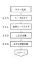
以下、本発明の特徴であるVベルト外れ異常検知処理を中心に、マイコン50の処理動作を図5〜図8のフローチャートに沿って以下に説明する。
図5、図6は電源投入から乾燥運転が終了するまでの全体のフローチャートである。まず、電源キー40がONされると(ステップS1)、マイコン50はリセット回路70からのリセット信号を受けて初期設定処理を実行し(ステップS2)、これにより各種フラグや変数等がリセットされる。
【0033】
使用者により衣類がドラム13内へ収容されスタートキー41が押されると(ステップS3)、マイコン50はモータ目標回転速度を例えば1150rpmに設定してモータ27を始動させる(ステップS4)。また、モータ27の始動とほぼ同時に、Vベルト外れ判定時間カウント用のタイマA及び運転時間カウント用のタイマBの計時を開始する(ステップS5)。これにより、モータ27の回転速度は目標回転速度にまで急速に上昇し、ドラム13及び両面ファン20はそれぞれの減速比により定まった所定の回転速度にて回転する。
【0034】
Vベルト外れ判定時間カウント用のタイマAの計時が55秒に到達すると(ステップS6)、モータON信号をゼロにすることによりモータ27の駆動電流を遮断する(ステップS7)。これにより、モータ27はその直前の回転による惰性で回る。また、これとほぼ同時に、Vベルト外れ判定時間カウント用のタイマAをリセットして計時を再度スタートさせる(ステップS8)と共に、モータ回転数カウンタをリセットして計数を開始する(ステップS9)。このモータ回転数カウンタは、モータ27が1回転する毎に1個発生するパルス信号を回転数検出回路63から受けて、これを計数するカウンタである。なお、ステップS6における経過時間は、モータ27が目標回転速度に到達するのに充分な時間程度以上の長さで適宜定めることができるが、乾燥運転のできるだけ早い時点で異常検知を行なうためには短く設定しておく方が好ましい。
【0035】
Vベルト外れ判定時間カウント用のタイマAの計時が5秒に到達すると(ステップS10)、モータ回転数カウンタの値を予め定めたモータ回転数判定閾値の初期値(この場合は80)と比較し(ステップS11)、モータ回転数カウンタの値の方が大きい場合にはステップS30へ進みエラー処理を実行する。すなわち、Vベルト32が正常に機能してドラム13を回転駆動している場合には、プーリ31に大きな負荷がかかるため、惰性による回転力は急速に減衰し5秒間のモータ回転数は小さな値となる。逆に、Vベルト32が切れたり外れたりしてプーリ31が殆ど無負荷の状態で回転している場合には、惰性による回転力が維持されるため、5秒間のモータ回転数は大きなものとなる。従って、ステップS11におけるモータ回転数判定閾値の初期値は、上記判定が行なえるような適当な値に予め定められる。
【0036】
ステップS11にてモータ回転数カウンタの値が80以下である場合には、ドラム13の回転駆動は正常であると判断し、目標回転速度を所定の値に設定してモータ27の駆動を再開すると共に加熱ヒータ25への通電を開始させ、乾燥運転をスタートする(ステップS12)。以上が乾燥運転の初期におけるVベルト外れ異常検知の処理動作である。
【0037】
運転時間カウント用のタイマBの計時が60分を経過したならば(ステップS13)、再びVベルト外れ異常検知処理を実行する。まず、小トルク判定処理を行なうことにより比較通電角を決定し(ステップS14)、その時点での実際の通電角αと比較通電角とを比較する(ステップS15)。小トルク判定処理の詳細については図7を参照して後述する。
【0038】
一定回転速度にてモータ27を回転制御する際、モータ27の回転負荷が大きいほど通電角αは大きくなる。従って、通電角αの大きさを判定することによりモータ27に対する負荷を推定することができる。この衣類乾燥機では、出口温度センサ35で検出された出口温度と雰囲気温度センサ39で検出された基板温度との温度差が所定値以上に大きくなったことを自動的に検知して乾燥運転を終了するようにしている。このため、通常、ドラム13に収容された衣類の量が少ない場合、衣類の水分は比較的短時間の内に蒸発し出口温度は高くなるから、乾燥運転時間は60分に達しない。すなわち、ステップS14までに乾燥運転は終了している。従って、乾燥運転が60分に至るまで継続されているのは、ドラム13に収容された衣類の量が多いか、或いは、衣類の量は少ないが例えば繊維の性質上極めて乾きにくい等の理由に依ると推測できる。
【0039】
換言すれば、乾燥運転時間が60分を経過した後にモータ27に対する負荷が小さい場合は、衣類の量は少ないが何らかの理由(例えば乾きにくい)により運転時間が長くなっているか、或いは、Vベルト切れや外れ等によりドラム13の回転駆動に異常を生じている可能性が高いと判断できる。そこで、ステップS15にて実際の通電角αが比較通電角以下である場合にはステップS16以降へ進み、Vベルト外れの異常検知処理を行なう。一方、実際の通電角αが比較通電角よりも大きい場合にはステップS34へ進む。
【0040】
ステップS16では、Vベルト外れ判定回数カウンタ(JCT)の計数値が3以上であるか否かを判定する。計数値が3未満であるときにステップS17へ進み、計数値が3以上であるときには上記ステップS15にて通電角αが比較通電角よりも大きいときと同様にステップS34へ進む。
【0041】
ステップS17〜S22の処理は、タイマBの作動を除き上記ステップS5〜S10の処理と同じである。ステップS17では、Vベルト外れ判定時間カウント用のタイマAがリセットされて再び計時が開始される。Vベルト外れ判定時間カウント用のタイマAの計時が55秒に到達すると(ステップS18)、モータON信号をゼロにすることによりモータ27の駆動電流を遮断する(ステップS19)。これにより、モータ27はその直前の回転の惰性によって回る。そして、ほぼ同時に、Vベルト外れ判定時間カウント用のタイマAをリセットして計時を再びスタートさせる(ステップS20)と共に、モータ回転数カウンタをリセットし計数を開始する(ステップS21)。
【0042】
Vベルト外れ判定時間カウント用のタイマAの計時が5秒に到達すると(ステップS22)、その時点でのモータ27の回転速度が、1100rpm以下、1100〜1200rpm、1200〜1300rpm、1300rpm以上のいずれの範囲に属するかによって、モータ回転数判定閾値がそれぞれ75、83、91、100の値に設定される(ステップS23、S24、S25、S26、S27、S28、S29)。そして、モータ回転数カウンタの値をそのモータ回転数判定閾値と比較し(ステップS30)、モータ回転数カウンタの値の方が大きい場合にはステップS31へ進んでエラー処理を実行する。
【0043】
ステップS30にてモータ回転数カウンタの値がモータ回転数判定閾値以下である場合には、ドラム13の回転駆動は正常であると判断することができるのでステップS32へ進み、モータ27の駆動を再開し、更に、Vベルト外れ判定回数カウンタ(JCT)の計数値を1つアップする(ステップS33)。そして、その他の乾燥運転処理を実行し(ステップS34)、運転時間カウント用のタイマBが所定の乾燥運転時間に達したか否かを判定する(ステップS35)。ステップS35にて所定の乾燥運転時間が経過したと判定されたとき、クールダウン運転へ移行する(ステップS36)。所定の乾燥運転時間が経過していないと判定されたときには、ステップS14へと戻り再び小トルク判定処理を実行する。
【0044】
Vベルト外れ判定回数カウンタは初期設定時にリセットされており、ステップS33にてカウントアップされ、ステップS16にてその計数値が判定される。つまり、Vベルト外れ判定回数カウンタはVベルト外れの異常検知処理が行なわれる毎にカウントアップされ、通電角αが比較通電角以下であると判定されたときにVベルト外れの異常検知処理の直前にその計数値が判定される。従って、このフローチャートによれば、乾燥運転が終了するまで小トルク判定処理(ステップS14)及び通電角αの判定(ステップS15)は繰り返し実行され、ステップS15にて通電角αが比較通電角よりも小さいときに行なわれるVベルト外れの異常検知処理は最大3回実行される。すなわち、通電角αが比較通電角以下であっても惰性回転中のモータ27の回転数の判定(ステップS30)により正常であると判定されることが3回続くと、それ以降はVベルト外れの異常検知処理は行なわれない。
【0045】
なお、図5、図6には示していないが、ステップS35に至るまでの間においても、運転時間カウント用のタイマBの計時は適当な間隔毎に所定の乾燥運転時間に到達しているか否かが判定され、所定の乾燥運転時間に至った時点で加熱ヒータ25は停止されクールダウン運転へと移行する。
【0046】
次に、上記ステップS14の小トルク判定処理について図7のフローチャートを参照して説明する。小トルク判定処理は、通電角αの大きさを判定する基準である比較通電角をその時点のモータ27の回転速度に応じて決定する処理である。まず、電源の周波数が60Hzであるか否かを判定し(ステップS40)、60Hzである場合には、その時点でのモータ27の回転速度が1100rpm以下、1100〜1200rpm、1200〜1300rpm、1300rpm以上のいずれの範囲に属するかによって、比較通電角をそれぞれ10°、13°、16°、19°に設定する(ステップS41、S42、S43、S44、S45、S46、S47)。また、電源の周波数が50Hzである場合には、その時点でのモータ27の回転速度が1100rpm以下、1100〜1200rpm、1200〜1300rpm、1300rpm以上のいずれの範囲に属するかによって、比較通電角をそれぞれ15°、19°、23°、27°に設定する(ステップS48、S49、S50、S51、S52、S53、S54)。
【0047】
すなわち、同一電源周波数に対しては、モータ27の回転速度が速いほど供給する電力は大きくなるので大きな通電角αが必要である。このため、比較通電角もこれに応じて大きな値とする。また、電源周波数が低い場合には単位時間(例えば1秒)当たりの電圧の波数が少ないため、同一電力をモータ27に供給するためには通電角αを大きくしなければならない。比較通電角は、このような条件を考察して予め適当に定められる。
【0048】
次に、上記ステップS30のエラー処理について図8のフローチャートを参照して説明する。エラー処理においては、モータON信号をゼロにすることによりモータ27の回転制御を停止し(ステップS60)、第1、第2加熱ヒータ25a、25bに供給している電流を遮断し加熱も停止する(ステップS61)。また、LED点灯回路62を駆動し、異常発生時の表示動作として、「残り10分」、「乾燥1」乃至「乾燥2」、「ヒータ切換弱」、「標準乾燥コース」の各LEDをいずれも点滅させる(ステップS62)。更に、オートパワーオフ回路(APO)67を作動させるまでの時間を短い値に設定する(ステップS63)。例えば、正常に乾燥運転を終了した場合にはオートパワーオフ時間を5分とし、異常が発生した場合にはオートパワーオフ時間を1分程度に設定する。そして、異常発生によりモータ27や加熱ヒータ25の駆動が停止された後に、そのオートパワーオフ時間が経過したならば自動的に電源を遮断する。
【0049】
また、図8の処理ではLEDの点滅により使用者に異常を報知するようにしているが、更に、ブザー回路64を駆動し電子ブザー45の警告音により使用者の注意を喚起するようにしても良い。
【0050】
なお、上記実施例は一例であって、本発明の趣旨に沿った範囲で適宜変形や修正を行なえることは明らかである。
【図面の簡単な説明】
【図1】本発明の一実施例である衣類乾燥機の側面縦断面図。
【図2】この衣類乾燥機の操作パネルの外観を示す正面図。
【図3】この衣類乾燥機の電気系構成図。
【図4】この衣類乾燥機のモータ回転制御の動作説明のための波形図。
【図5】この衣類乾燥機におけるVベルト外れ異常検知処理のフローチャート。
【図6】この衣類乾燥機におけるVベルト外れ異常検知処理のフローチャート。
【図7】Vベルト外れ異常検知処理の中の小トルク判定処理のフローチャート。
【図8】Vベルト外れ異常検知処理の中のエラー処理のフローチャート。
【符号の説明】
13…ドラム
27…モータ
31…プーリ
32…Vベルト
34…回転センサ
50…マイコン
63…回転数検出回路
64…ブザー回路
66…商用電源ゼロクロス信号検出回路
68…負荷駆動回路[0001]
TECHNICAL FIELD OF THE INVENTION
The present invention relates to a clothes dryer.
[0002]
[Prior art]
A household clothes dryer supplies dry hot air into a drum containing wet clothes, cools the hot hot air containing moisture evaporated from the clothes, dehumidifies the air, and uses the heater to dry the dried air. It is configured to reheat and circulate to the drum. The drum is rotated slowly about a horizontal axis, which causes the clothes in the drum to be agitated and an even drying to be performed.
[0003]
Generally, in such a clothes dryer, only a single motor is provided for rotating a fan and a drum for generating circulating air, respectively, and a rotation shaft of the motor is provided through a transmission mechanism such as a pulley or a V-belt. Thus, the fan and the drum are driven to rotate at predetermined rotation speeds. The rotation transmission mechanism on the drum side includes a pulley attached to the rotation shaft of the motor, a V-belt wound around the pulley and the outer peripheral surface of the cylindrical drum, and a tension mechanism for applying tension to the V-belt. I have.
[0004]
[Problems to be solved by the invention]
In the above-mentioned clothes dryer, if the V-belt is cut off or comes off, or if the tension mechanism fails and tension cannot be applied to the V-belt, the drum does not rotate normally or stops. In such a case, since the hot air intensively blows on the clothing accumulated near the outlet of the hot air into the drum, the clothing becomes abnormally high temperature, and depending on the type of fiber, discoloration or burning may occur. is there.
[0005]
In order to detect such an abnormal state, for example, in the invention described in Japanese Patent Application Laid-Open No. 60-48795, displacement of a spring of a tension mechanism is detected. However, if abnormality detection is performed using such a mechanical structure, special mechanical parts are required, the cost is increased, and assembly is time-consuming.
[0006]
SUMMARY OF THE INVENTION The present invention has been made to solve the above-described problem, and an object of the present invention is to perform abnormal heating of clothes in a drum by reliably detecting a belt abnormality such as a belt breakage or detachment with a simple configuration. It is an object of the present invention to provide a clothes dryer capable of preventing the occurrence of garbage.
[0007]
[Means for Solving the Problems]
The first clothes dryer of the present invention made in order to solve the above-mentioned problem sends hot air heated by a heater to a drum containing clothes, cools air passing through the drum and dehumidifies the air. A clothes dryer that circulates the drying air, wherein the clothes dryer transmits a rotational driving force of a motor to a drum via a belt.
a) rotation speed detection means for detecting the rotation speed of the motor,
b) At the beginning of operationBefore starting the energization of the heater,Drive control means for stopping power supply to the motor for a second predetermined time after driving the motor for a first predetermined time;
c) counting means for counting the number of rotations of the motor detected by the rotation number detecting means within the second predetermined time,
d) abnormality detecting means for stopping operation when the count value of the counting means exceeds a predetermined value;
Equipped,
When the count value of the counting means is equal to or less than a predetermined value, the drive of the motor is restarted and the energization of the heater is started.It is characterized by:
[0008]
In a second clothes dryer according to the present invention, in the first clothes dryer, the drive control means stops supplying power to the motor for a third predetermined time even after a predetermined drying operation time has elapsed, and The means counts the number of rotations of the motor detected by the rotation number detecting means within a third predetermined time, and the abnormality detecting means stops the operation when the count value of the counting means exceeds a predetermined value. It is characterized by: Here, if the third predetermined time is the same as the second predetermined time, the configuration can be simplified.
[0009]
In the third clothes dryer of the present invention, in the second clothes dryer, when performing an abnormality detection after a predetermined drying operation time has elapsed, the load on the motor is estimated before the power supply to the motor is stopped. A load estimating means for performing the abnormality detection, and when it is determined that the load amount is equal to or less than a predetermined value, the power supply to the motor is stopped to detect the abnormality.
[0010]
In the fourth clothes dryer of the present invention, in the third clothes dryer, particularly when controlling the rotation of the motor by phase control, the load estimating means controls the motor to rotate at a predetermined rotation speed. It is characterized in that the phase control angle corresponding to the amount of power supplied to the motor when performing the control is determined.
[0011]
The fifth clothes dryer of the present invention drives the motor for the fourth predetermined time in the third clothes dryer, when no abnormality is detected in the abnormality detection after the predetermined drying operation time has elapsed. A plurality of abnormal detection operations are performed in which the energization of the motor is stopped for a third predetermined time and a value obtained by counting the number of rotations of the motor detected by the rotation speed detection means within the third predetermined time is compared with a predetermined value. It is characterized in that the drying operation is continued repeatedly when no abnormality is detected in any case. Here, if the fourth predetermined time and the first predetermined time are the same, the configuration can be simplified.
[0012]
BEST MODE FOR CARRYING OUT THE INVENTION
In the first clothes dryer, the drive control means starts the drying operation,Before energizing the heater,A driving current is supplied to the motor so that the motor increases to a predetermined steady-state rotation speed, and the driving is temporarily stopped after a first predetermined time has elapsed. Here, the first predetermined time is set in advance to a time sufficient for the motor to reach a substantially predetermined steady-state rotation speed. When the drive control means stops driving the motor, the motor continues to rotate due to the inertia of rotation immediately before the stop of the drive. During the inertial rotation, if the load on the motor is large, the rotation speed is rapidly reduced. However, if the load on the motor is small, the degree of reduction of the rotation speed is small and a relatively high rotation speed is temporarily maintained. The counting means grasps the rotation state of the motor during the inertial rotation by counting a pulse signal synchronized with the rotation of the motor obtained from the rotation number detection means during the second predetermined time during which the motor driving is stopped. I do. If the motor drives the drum in a normal state via the belt, an appropriate load should be applied to the motor, so that the rotational speed of the motor is surely reduced during the inertial rotation. On the other hand, when the drum is not rotationally driven due to belt breakage or detachment, the rotational speed of the motor does not decrease so much during the inertial rotation, so the abnormality detecting means should compare the count value of the motor rotation with a predetermined value. And the drying operation is stopped when the abnormality is detected.On the other hand, if it is determined that the rotational driving of the drum is normal, the driving of the motor is restarted and the power supply to the heater is started.
[0013]
The above-described abnormality detection operation is performed at the beginning of the drying operation. If an abnormality such as a belt breakage or detachment occurs during the drying operation, it is desirable to detect the abnormality during the cycle of the drying operation. Therefore, in the second clothes dryer, the drive control means causes the motor to rotate by inertia by stopping the drive of the motor for the third predetermined time even after the predetermined drying operation time has elapsed. The counting means counts a pulse signal synchronized with the rotation of the motor obtained from the rotation speed detecting means during the third predetermined time during which the driving of the motor is stopped. If the count value exceeds a predetermined value, the abnormality detecting means determines that an abnormality has occurred during the drying operation, and stops the drying operation.
[0014]
It is to be noted that temporarily stopping the driving of the motor during the drying operation as described above degrades the drying performance. Therefore, it is desirable to avoid the case where there is no possibility of occurrence of an abnormality or when it is extremely small. Therefore, in the third clothes dryer, when performing abnormality detection after a predetermined drying operation time has elapsed, first, the load estimating unit determines whether or not abnormality has occurred without stopping driving of the motor. The load is detected, and if the load is equal to or less than a predetermined value, it is determined that there is a high possibility that an abnormality such as a belt breakage or separation has occurred. Only in this case, the drive control means stops driving of the motor, rotates the motor by inertia, and executes abnormality detection based on the motor speed.
[0015]
By the way, when the rotation control of the motor is performed by the phase control, a triac or the like which outputs a motor ON signal and turns on / off a motor current at a point of time when a certain time is delayed from a zero crossing point of an AC power supply is usually conducted, and the motor is turned on. To start energizing. The amount of power supplied to the motor is changed by adjusting the relative phase angle (within the range of 0 ° to 180 °) at the time when the motor is turned on with the zero cross point being 0 °, thereby controlling the motor rotation. When controlling the motor to rotate at the same rotational speed, a larger torque is required as the load on the motor increases, so it is necessary to supply a larger electric power to the motor. Therefore, in the fourth clothes dryer, for example, the conduction angle which is the angle from the zero cross point to the motor ON time, or the conduction angle which is the angle from the motor ON time to a predetermined relative phase angle position, Estimate the motor load. For example, since the energization angle is smaller as the load amount is smaller, the energization angle is compared with a predetermined angle, and when the energization angle is equal to or smaller than the predetermined angle, it is determined that the load amount is abnormally small and there is a possibility that the belt may break or come off.
[0016]
Further, in order to more reliably perform the abnormality detection after the predetermined drying operation time has elapsed, the same abnormality detection operation is performed not only once but also a plurality of times as in the fifth clothes dryer. It is preferable to continue the drying operation in the case where no abnormality is recognized in the above. Of course, if the number of repetitions is increased, the reliability of the abnormality detection is increased, but the rotation speed of the drum is frequently decreased, and not only the drying performance is deteriorated but also the impression given to the user is not good. Therefore, it is appropriate to set the number of repetitions of abnormality detection to about three.
[0017]
【The invention's effect】
According to the first clothes dryer of the present invention, immediately after the start of the drying operation, it is detected whether or not the drum is rotating normally. If the rotation of the drum is not normal, the drying operation is stopped. For this reason, it is possible to reliably detect the occurrence of an abnormality such as breakage or detachment of the V-belt before the drying operation, so that abnormal heating of the clothes in the drum can be prevented.
[0018]
Further, according to the second clothes dryer, it is detected whether or not the drum is rotating normally even after a predetermined drying operation time has elapsed. The drying operation is stopped. For this reason, it is possible to reliably and promptly detect the occurrence of an abnormality such as breakage or detachment of the V-belt during the drying operation, so that abnormal heating of the clothes in the drum can be prevented.
[0019]
Further, according to the third and fourth clothes dryers, the motor load is estimated without lowering the rotation of the drum when the abnormality is detected after the predetermined drying operation time has elapsed, and the motor load is lightened. When the possibility of running out of the belt is high, the rotation speed of the drum is reduced to detect an abnormality. For this reason, the rotation speed of the drum does not decrease due to the abnormality detection even though there is almost no possibility of the V-belt being broken, so that the drying performance is maintained and the impression to the user is not reduced. .
[0020]
Furthermore, according to the fifth clothes dryer, the abnormality detection is repeatedly performed a plurality of times after the elapse of the predetermined drying operation time, so that missed detection is significantly reduced and reliability is increased.
[0021]
【Example】
Hereinafter, an embodiment of a clothes dryer according to the present invention will be described with reference to FIGS. First, the overall configuration of the clothes dryer will be described with reference to a side vertical sectional view of FIG. A
[0022]
In the drying
[0023]
In the
[0024]
A lower portion of the drying
[0025]
A
[0026]
During the drying operation, the
[0027]
An
[0028]
FIG. 2 is a front view showing the appearance of the
[0029]
Next, the electrical configuration of the
[0030]
In the clothes dryer having the above configuration, first, the rotation control of the
[0031]
In the
[0032]
Hereinafter, the processing operation of the
FIG. 5 and FIG. 6 are flowcharts of the entire process from turning on the power to the end of the drying operation. First, when the
[0033]
When the user puts the clothes in the
[0034]
When the timer A for counting the V-belt detachment determination time reaches 55 seconds (step S6), the drive current of the
[0035]
When the count of the timer A for counting the V belt slippage determination time reaches 5 seconds (step S10), the value of the motor rotation speed counter is compared with a predetermined initial value of the motor rotation speed determination threshold value (80 in this case). (Step S11) If the value of the motor speed counter is larger, the process proceeds to step S30 to execute error processing. That is, when the V-
[0036]
If the value of the motor rotation counter is equal to or less than 80 in step S11, it is determined that the rotation of the
[0037]
If the time counted by the timer B for counting the operation time has passed 60 minutes (step S13), the V-belt detachment abnormality detection processing is executed again. First, the comparison energization angle is determined by performing a small torque determination process (step S14), and the actual energization angle α at that time is compared with the comparison energization angle (step S15). Details of the small torque determination process will be described later with reference to FIG.
[0038]
When controlling the rotation of the
[0039]
In other words, when the load on the
[0040]
In step S16, it is determined whether or not the count value of the V belt slippage determination frequency counter (JCT) is 3 or more. When the count value is less than 3, the process proceeds to step S17. When the count value is 3 or more, the process proceeds to step S34 in the same manner as when the conduction angle α is larger than the comparison conduction angle in step S15.
[0041]
The processing in steps S17 to S22 is the same as the processing in steps S5 to S10 except for the operation of the timer B. In step S17, the timer A for counting the V-belt detachment determination time is reset, and time counting is started again. When the timer A for counting the V-belt detachment determination time reaches 55 seconds (step S18), the drive current of the
[0042]
When the timer A for V-belt detachment determination time count reaches 5 seconds (step S22), the rotation speed of the
[0043]
If the value of the motor rotation speed counter is equal to or smaller than the motor rotation speed determination threshold value in step S30, it can be determined that the rotation drive of the
[0044]
The V-belt disengagement determination counter is reset at the time of initial setting, and is counted up in step S33, and the count value is determined in step S16. That is, the V-belt disengagement determination counter is incremented every time the V-belt disengagement abnormality detection process is performed, and immediately before the V-belt disengagement abnormality detection process is determined when the energization angle α is determined to be equal to or smaller than the comparative energization angle. , The count value is determined. Therefore, according to this flowchart, the small torque determination process (Step S14) and the determination of the energization angle α (Step S15) are repeatedly executed until the drying operation ends, and in Step S15, the energization angle α is smaller than the comparative energization angle. The abnormality detection processing for V-belt detachment performed when the distance is small is executed up to three times. That is, even if the energizing angle α is equal to or smaller than the comparative energizing angle, if it is determined that the rotation speed of the
[0045]
Although not shown in FIGS. 5 and 6, even before step S35, the timer B for counting the operation time counts whether the predetermined drying operation time has been reached at appropriate intervals. When the predetermined drying operation time is reached, the
[0046]
Next, the small torque determination process in step S14 will be described with reference to the flowchart in FIG. The small torque determination process is a process of determining a comparison conduction angle, which is a reference for determining the magnitude of the conduction angle α, according to the rotation speed of the
[0047]
In other words, for the same power supply frequency, the higher the rotation speed of the
[0048]
Next, the error processing in step S30 will be described with reference to the flowchart in FIG. In the error processing, the rotation control of the
[0049]
In the process of FIG. 8, the user is notified of the abnormality by the blinking of the LED. However, the buzzer circuit 64 may be driven to further alert the user by a warning sound of the
[0050]
It should be noted that the above embodiment is merely an example, and it is apparent that modifications and modifications can be made as appropriate within the scope of the present invention.
[Brief description of the drawings]
FIG. 1 is a side longitudinal sectional view of a clothes dryer according to one embodiment of the present invention.
FIG. 2 is a front view showing the appearance of an operation panel of the clothes dryer.
FIG. 3 is an electrical configuration diagram of the clothes dryer.
FIG. 4 is a waveform diagram for explaining the operation of motor rotation control of the clothes dryer.
FIG. 5 is a flowchart of a V-belt detachment abnormality detection process in the clothes dryer.
FIG. 6 is a flowchart of a V belt detachment abnormality detection process in the clothes dryer.
FIG. 7 is a flowchart of a small torque determination process in the V-belt detachment abnormality detection process.
FIG. 8 is a flowchart of an error process in a V-belt detachment abnormality detection process.
[Explanation of symbols]
13 ... drum
27 ... Motor
31 ... Pulley
32 ... V belt
34 ... Rotation sensor
50 ... microcomputer
63: rotation speed detection circuit
64 ... Buzzer circuit
66. Commercial power supply zero-cross signal detection circuit
68 ... Load drive circuit
Claims (5)
Translated fromJapanesea)モータの回転数を検出する回転数検出手段と、
b)運転初期において、前記ヒータへの通電を開始する前に、第1の所定時間モータを駆動した後に第2の所定時間モータへの通電を停止する駆動制御手段と、
c)前記第2の所定時間内に前記回転数検出手段により検出したモータの回転数を計数する計数手段と、
d)該計数手段の計数値が所定の値を越えている場合に運転を停止する異常検知手段と、
を備え、
前記計数手段の計数値が所定の値以下である場合には、前記モータの駆動を再開すると共に前記ヒータの通電を開始させることを特徴とする衣類乾燥機。A clothes dryer that sends hot air heated by a heater to a drum containing clothes, cools air that has passed through the drum, dehumidifies the air, and then circulates the dry air. In the clothes dryer transmitting to the drum via
a) rotation speed detection means for detecting the rotation speed of the motor,
b) in the initial stageof operation, before starting energization of the heater, drive control means for driving the motor for a first predetermined time and then stopping energization of the motor for a second predetermined time;
c) counting means for counting the number of rotations of the motor detected by the rotation number detecting means within the second predetermined time,
d) abnormality detecting means for stopping operation when the count value of the counting means exceeds a predetermined value;
Equipped witha,
When the count value of the counting means is equal to or less than a predetermined value, the driving of the motor is restarted and the energization of the heater is started .
Priority Applications (6)
| Application Number | Priority Date | Filing Date | Title |
|---|---|---|---|
| JP21941896AJP3568328B2 (en) | 1996-07-31 | 1996-07-31 | Clothes dryer |
| TW085216918UTW377765U (en) | 1996-07-31 | 1996-11-05 | Outside mask apparatus for whole-covering ceiling fan |
| TW086210779UTW370982U (en) | 1996-07-31 | 1997-06-30 | Cloth drier |
| US08/898,111US5852881A (en) | 1996-07-31 | 1997-07-22 | Clothes dryer |
| KR1019970036056AKR100208409B1 (en) | 1996-07-31 | 1997-07-30 | Clothes drying machine |
| DE19732932ADE19732932B4 (en) | 1996-07-31 | 1997-07-31 | clothes dryer |
Applications Claiming Priority (1)
| Application Number | Priority Date | Filing Date | Title |
|---|---|---|---|
| JP21941896AJP3568328B2 (en) | 1996-07-31 | 1996-07-31 | Clothes dryer |
Publications (2)
| Publication Number | Publication Date |
|---|---|
| JPH1043494A JPH1043494A (en) | 1998-02-17 |
| JP3568328B2true JP3568328B2 (en) | 2004-09-22 |
Family
ID=16735090
Family Applications (1)
| Application Number | Title | Priority Date | Filing Date |
|---|---|---|---|
| JP21941896AExpired - Fee RelatedJP3568328B2 (en) | 1996-07-31 | 1996-07-31 | Clothes dryer |
Country Status (5)
| Country | Link |
|---|---|
| US (1) | US5852881A (en) |
| JP (1) | JP3568328B2 (en) |
| KR (1) | KR100208409B1 (en) |
| DE (1) | DE19732932B4 (en) |
| TW (2) | TW377765U (en) |
Families Citing this family (54)
| Publication number | Priority date | Publication date | Assignee | Title |
|---|---|---|---|---|
| KR100678671B1 (en)* | 2000-01-18 | 2007-02-05 | 삼성전자주식회사 | Belt failure prevention device and method of dryer |
| US6637127B2 (en)* | 2001-10-02 | 2003-10-28 | Tyco Electronics Corporation | Dryer airflow sensor |
| KR20040021099A (en)* | 2002-09-02 | 2004-03-10 | 엘지전자 주식회사 | Clothes dryer and method for controlling the same |
| KR100487345B1 (en)* | 2002-11-26 | 2005-05-03 | 엘지전자 주식회사 | Dryer and Control Method of Cooling Time for the same |
| US20070144033A1 (en)* | 2003-06-24 | 2007-06-28 | Kocjan Tomasz P | System and method for operating a drying unit |
| US7347008B2 (en)* | 2003-06-24 | 2008-03-25 | M&R Printing Equipment, Inc. | System and method for controlling the operating parameters of a setting system |
| KR101010466B1 (en)* | 2003-08-26 | 2011-01-21 | 엘지전자 주식회사 | Dryer with belt loosening detection and control method |
| KR100987436B1 (en) | 2003-07-25 | 2010-10-13 | 엘지전자 주식회사 | Dryer with belt breakage detection device and control method thereof |
| US6996920B2 (en)* | 2003-07-25 | 2006-02-14 | Lg Electronics Inc. | Control method and system for clothes dryer |
| KR101073904B1 (en)* | 2003-12-26 | 2011-10-17 | 엘지전자 주식회사 | dryer having function of sensing the amount of cumulative lint |
| NZ555019A (en)* | 2004-11-11 | 2010-09-30 | Fisher & Paykel Appliances Ltd | A method of reducing a risk of fire in a laundry appliance and an appliance incorporating said method |
| US20060106693A1 (en)* | 2004-11-12 | 2006-05-18 | International Business Machines Corporation | Unified banking services via a single financial account |
| US20060106696A1 (en)* | 2004-11-12 | 2006-05-18 | International Business Machines Corporation | Account transfer using a single financial account |
| US20060106695A1 (en)* | 2004-11-12 | 2006-05-18 | International Business Machines Corporation | Real-time credit rating using a single financial account |
| US20060106694A1 (en)* | 2004-11-12 | 2006-05-18 | International Business Machines Corporation | Transfer of deposit and debit subscriptions using a single financial account |
| DE102004055940A1 (en)* | 2004-11-19 | 2006-05-24 | BSH Bosch und Siemens Hausgeräte GmbH | Method and device for safe operation of a program-controlled tumble dryer |
| DE102006002713A1 (en)* | 2005-03-18 | 2006-10-12 | BSH Bosch und Siemens Hausgeräte GmbH | Front assembly for a laundry drying machine |
| CA2505565C (en)* | 2005-04-28 | 2008-09-16 | Camco Inc. | Apparatus and method for controlling a clothes dryer |
| US8015726B2 (en)* | 2005-06-23 | 2011-09-13 | Whirlpool Corporation | Automatic clothes dryer |
| US20060288608A1 (en)* | 2005-06-23 | 2006-12-28 | Carow James P | Automatic clothes dryer |
| US7921578B2 (en)* | 2005-12-30 | 2011-04-12 | Whirlpool Corporation | Nebulizer system for a fabric treatment appliance |
| EP2013403B2 (en)* | 2006-04-14 | 2016-12-07 | LG Electronics Inc. | Dryer and controlling method thereof |
| US20080040946A1 (en)* | 2006-08-15 | 2008-02-21 | American Dryer Corporation | Method of drying clothing with auto shut off and prorated billing |
| US9249539B2 (en)* | 2006-09-25 | 2016-02-02 | Ecolab Inc. | Determination of dryness of textiles in a dryer |
| KR101276041B1 (en)* | 2006-09-29 | 2013-06-20 | 엘지전자 주식회사 | apparatus for drying laundary and controlling method of the same |
| KR101218031B1 (en)* | 2006-10-09 | 2013-01-02 | 엘지전자 주식회사 | Method for dryer |
| US7992321B2 (en)* | 2007-12-19 | 2011-08-09 | Electrolux Home Products | Laundry dryer having three roller drum support system and reversing idler assembly |
| DE102008019921A1 (en) | 2008-04-21 | 2009-10-22 | BSH Bosch und Siemens Hausgeräte GmbH | Domestic appliance for drying laundry items and method for operating such a domestic appliance |
| CN102439212B (en) | 2009-07-01 | 2015-04-08 | Lg电子株式会社 | Washing machine and control method thereof |
| WO2011080056A1 (en) | 2009-12-16 | 2011-07-07 | Arcelik Anonim Sirketi | A laundry dryer wherein belt rupture is prevented |
| CN201797081U (en) | 2010-07-08 | 2011-04-13 | 富士康(昆山)电脑接插件有限公司 | electrical connector |
| DE102010031266A1 (en)* | 2010-07-13 | 2012-01-19 | BSH Bosch und Siemens Hausgeräte GmbH | Method for detecting failure of belt of belt drive device in household appliance for care of laundry items, involves driving wash drum by drive motor in functional condition of belt of belt drive device |
| JP5573596B2 (en)* | 2010-10-28 | 2014-08-20 | パナソニック株式会社 | Drum washing machine |
| DK2333149T3 (en)* | 2010-11-22 | 2014-01-06 | V Zug Ag | Dryer with ambient temperature sensor |
| US8782922B2 (en) | 2010-11-24 | 2014-07-22 | Ecolab Usa Inc. | Dryer monitoring |
| KR101809130B1 (en)* | 2011-03-29 | 2017-12-14 | 엘지전자 주식회사 | A clothes dryer |
| US9206543B2 (en) | 2011-10-14 | 2015-12-08 | Ecolab Usa Inc. | Dryer monitoring |
| KR102025181B1 (en)* | 2013-04-03 | 2019-09-26 | 삼성전자주식회사 | Clothing dryer and control method thereof |
| AU2013394134A1 (en)* | 2013-07-09 | 2016-01-21 | Electrolux Appliances Aktiebolag | Appliance for drying laundry with enhanced operation flexibility |
| KR101592318B1 (en)* | 2014-12-09 | 2016-02-05 | 엘지전자 주식회사 | Dryer |
| CN106149283A (en)* | 2015-04-28 | 2016-11-23 | 青岛海尔洗衣机有限公司 | Rabbling mechanism fault judgment method and washing machine during a kind of flocculation treatment |
| US10113795B2 (en) | 2015-06-26 | 2018-10-30 | M&R Printing Equipment, Inc. | Dryer conveyor belt tracking system |
| US9939198B2 (en) | 2015-06-26 | 2018-04-10 | M&R Printing Equipment, Inc. | Dryer conveyor belt tracking system |
| CN104963164B (en) | 2015-07-31 | 2017-05-10 | 广东威灵电机制造有限公司 | Roller washing machine and control method and device thereof |
| US9951991B2 (en) | 2015-08-31 | 2018-04-24 | M&R Printing Equipment, Inc. | System and method for dynamically adjusting dryer belt speed |
| US10087572B2 (en)* | 2017-02-16 | 2018-10-02 | Whirlpool Corporation | Washing machine |
| CN109468813B (en)* | 2017-09-07 | 2022-03-08 | 无锡小天鹅电器有限公司 | Drying method and device |
| US10494758B2 (en)* | 2017-11-17 | 2019-12-03 | Haier Us Appliance Solutions, Inc. | Dryer appliances and methods of operation |
| WO2019108005A1 (en) | 2017-12-01 | 2019-06-06 | 엘지전자 주식회사 | Dryer and method for controlling same |
| KR102603457B1 (en)* | 2017-12-01 | 2023-11-17 | 엘지전자 주식회사 | Dryer and method for clothes |
| CN110318241B (en)* | 2018-03-30 | 2023-04-14 | 青岛胶南海尔洗衣机有限公司 | Method for controlling clothes dryer and clothes dryer |
| US11136705B2 (en) | 2019-05-15 | 2021-10-05 | Haier Us Appliance Solutions, Inc. | Detecting mechanical decoupling in a laundry appliance |
| WO2021257297A1 (en) | 2020-06-19 | 2021-12-23 | Ecolab Usa Inc. | Embedded temperature sensors for monitoring temperature of articles and status of drying or cleaning cycles |
| KR200494109Y1 (en)* | 2021-01-28 | 2021-08-04 | 주식회사 와스코 | Rotation sensing device for drum dryer |
Family Cites Families (8)
| Publication number | Priority date | Publication date | Assignee | Title |
|---|---|---|---|---|
| JPS6045879A (en)* | 1983-08-24 | 1985-03-12 | Nec Corp | Graphic input device |
| DE3332564A1 (en)* | 1983-09-09 | 1985-03-28 | Basf Ag, 6700 Ludwigshafen | MAGNETIC RECORDING CARRIERS |
| US4857813A (en)* | 1987-03-17 | 1989-08-15 | Jidosha Denki Kogyo Kabushiki Kaisha | Self-stopping motor control circuit |
| US5006778A (en)* | 1989-08-11 | 1991-04-09 | Whirlpool Corporation | Motor diagnostics and electronic control for a clothers dryer |
| DE4212325C2 (en)* | 1992-04-13 | 1994-05-05 | Hoechst Ag | Process for the production of concrete moldings with improved acid resistance and use of the concrete moldings produced thereafter |
| KR950005179Y1 (en)* | 1992-12-21 | 1995-06-26 | 구자홍 | Dehydration Control Device of Washing Machine |
| JPH078691A (en)* | 1993-06-24 | 1995-01-13 | Toshiba Corp | Clothes dryer |
| JP3030228B2 (en)* | 1995-04-14 | 2000-04-10 | 三洋電機株式会社 | Centrifugal dehydrator |
- 1996
- 1996-07-31JPJP21941896Apatent/JP3568328B2/ennot_activeExpired - Fee Related
- 1996-11-05TWTW085216918Upatent/TW377765U/enunknown
- 1997
- 1997-06-30TWTW086210779Upatent/TW370982U/enunknown
- 1997-07-22USUS08/898,111patent/US5852881A/ennot_activeExpired - Fee Related
- 1997-07-30KRKR1019970036056Apatent/KR100208409B1/ennot_activeExpired - Fee Related
- 1997-07-31DEDE19732932Apatent/DE19732932B4/ennot_activeExpired - Fee Related
Also Published As
| Publication number | Publication date |
|---|---|
| US5852881A (en) | 1998-12-29 |
| TW377765U (en) | 1999-12-21 |
| JPH1043494A (en) | 1998-02-17 |
| KR980009628A (en) | 1998-04-30 |
| KR100208409B1 (en) | 1999-07-15 |
| DE19732932A1 (en) | 1998-02-05 |
| TW370982U (en) | 1999-09-21 |
| DE19732932B4 (en) | 2004-09-02 |
Similar Documents
| Publication | Publication Date | Title |
|---|---|---|
| JP3568328B2 (en) | Clothes dryer | |
| JP3159599B2 (en) | Dryer | |
| EP0829569B1 (en) | Washer-dryer apparatus | |
| JP3208367B2 (en) | Drum type washer and dryer | |
| JP3263634B2 (en) | Clothes dryer | |
| JPH1043498A (en) | Clothes dryer | |
| JPH1085500A (en) | Clothes drier | |
| JP3717604B2 (en) | Clothes dryer | |
| JP3754302B2 (en) | Laundry equipment | |
| JP3767980B2 (en) | Clothes dryer | |
| JP3685559B2 (en) | Clothes dryer | |
| JP3109308B2 (en) | Clothes dryer | |
| JP3185487B2 (en) | Clothes dryer | |
| JPH11498A (en) | Clothes dryer | |
| JP3152578B2 (en) | Rotary drum type clothes dryer | |
| JPH0631100A (en) | Clothes drier | |
| JP3022154B2 (en) | Clothes dryer | |
| JP3030164B2 (en) | Clothes dryer | |
| JP3685560B2 (en) | Clothes dryer | |
| JPH10235066A (en) | Laundry equipment | |
| JP3177307B2 (en) | Laundry equipment | |
| JP3768035B2 (en) | Clothes dryer | |
| JP2604215B2 (en) | Clothes dryer | |
| JP3109302B2 (en) | Clothes dryer | |
| JPH078694A (en) | Clothes dryer |
Legal Events
| Date | Code | Title | Description |
|---|---|---|---|
| A977 | Report on retrieval | Free format text:JAPANESE INTERMEDIATE CODE: A971007 Effective date:20031201 | |
| A131 | Notification of reasons for refusal | Free format text:JAPANESE INTERMEDIATE CODE: A131 Effective date:20040113 | |
| A521 | Request for written amendment filed | Free format text:JAPANESE INTERMEDIATE CODE: A523 Effective date:20040303 | |
| TRDD | Decision of grant or rejection written | ||
| A01 | Written decision to grant a patent or to grant a registration (utility model) | Free format text:JAPANESE INTERMEDIATE CODE: A01 Effective date:20040601 | |
| A61 | First payment of annual fees (during grant procedure) | Free format text:JAPANESE INTERMEDIATE CODE: A61 Effective date:20040615 | |
| FPAY | Renewal fee payment (event date is renewal date of database) | Free format text:PAYMENT UNTIL: 20080625 Year of fee payment:4 | |
| FPAY | Renewal fee payment (event date is renewal date of database) | Free format text:PAYMENT UNTIL: 20090625 Year of fee payment:5 | |
| FPAY | Renewal fee payment (event date is renewal date of database) | Free format text:PAYMENT UNTIL: 20090625 Year of fee payment:5 | |
| FPAY | Renewal fee payment (event date is renewal date of database) | Free format text:PAYMENT UNTIL: 20100625 Year of fee payment:6 | |
| FPAY | Renewal fee payment (event date is renewal date of database) | Free format text:PAYMENT UNTIL: 20110625 Year of fee payment:7 | |
| FPAY | Renewal fee payment (event date is renewal date of database) | Free format text:PAYMENT UNTIL: 20110625 Year of fee payment:7 | |
| FPAY | Renewal fee payment (event date is renewal date of database) | Free format text:PAYMENT UNTIL: 20120625 Year of fee payment:8 | |
| FPAY | Renewal fee payment (event date is renewal date of database) | Free format text:PAYMENT UNTIL: 20120625 Year of fee payment:8 | |
| FPAY | Renewal fee payment (event date is renewal date of database) | Free format text:PAYMENT UNTIL: 20130625 Year of fee payment:9 | |
| S111 | Request for change of ownership or part of ownership | Free format text:JAPANESE INTERMEDIATE CODE: R313113 | |
| FPAY | Renewal fee payment (event date is renewal date of database) | Free format text:PAYMENT UNTIL: 20130625 Year of fee payment:9 | |
| R350 | Written notification of registration of transfer | Free format text:JAPANESE INTERMEDIATE CODE: R350 | |
| R250 | Receipt of annual fees | Free format text:JAPANESE INTERMEDIATE CODE: R250 | |
| R250 | Receipt of annual fees | Free format text:JAPANESE INTERMEDIATE CODE: R250 | |
| LAPS | Cancellation because of no payment of annual fees |