JP3568280B2 - Surgical operation support system - Google Patents
Surgical operation support systemDownload PDFInfo
- Publication number
- JP3568280B2 JP3568280B2JP17599695AJP17599695AJP3568280B2JP 3568280 B2JP3568280 B2JP 3568280B2JP 17599695 AJP17599695 AJP 17599695AJP 17599695 AJP17599695 AJP 17599695AJP 3568280 B2JP3568280 B2JP 3568280B2
- Authority
- JP
- Japan
- Prior art keywords
- image
- fluorescent
- affected part
- surgical operation
- fluorescent image
- Prior art date
- Legal status (The legal status is an assumption and is not a legal conclusion. Google has not performed a legal analysis and makes no representation as to the accuracy of the status listed.)
- Expired - Fee Related
Links
Images

Classifications
- A—HUMAN NECESSITIES
- A61—MEDICAL OR VETERINARY SCIENCE; HYGIENE
- A61B—DIAGNOSIS; SURGERY; IDENTIFICATION
- A61B90/00—Instruments, implements or accessories specially adapted for surgery or diagnosis and not covered by any of the groups A61B1/00 - A61B50/00, e.g. for luxation treatment or for protecting wound edges
- A61B90/36—Image-producing devices or illumination devices not otherwise provided for
- A—HUMAN NECESSITIES
- A61—MEDICAL OR VETERINARY SCIENCE; HYGIENE
- A61B—DIAGNOSIS; SURGERY; IDENTIFICATION
- A61B17/00—Surgical instruments, devices or methods
- A61B17/22—Implements for squeezing-off ulcers or the like on inner organs of the body; Implements for scraping-out cavities of body organs, e.g. bones; for invasive removal or destruction of calculus using mechanical vibrations; for removing obstructions in blood vessels, not otherwise provided for
- A61B2017/22082—Implements for squeezing-off ulcers or the like on inner organs of the body; Implements for scraping-out cavities of body organs, e.g. bones; for invasive removal or destruction of calculus using mechanical vibrations; for removing obstructions in blood vessels, not otherwise provided for after introduction of a substance
- A61B2017/22087—Implements for squeezing-off ulcers or the like on inner organs of the body; Implements for scraping-out cavities of body organs, e.g. bones; for invasive removal or destruction of calculus using mechanical vibrations; for removing obstructions in blood vessels, not otherwise provided for after introduction of a substance photodynamic
- A—HUMAN NECESSITIES
- A61—MEDICAL OR VETERINARY SCIENCE; HYGIENE
- A61B—DIAGNOSIS; SURGERY; IDENTIFICATION
- A61B90/00—Instruments, implements or accessories specially adapted for surgery or diagnosis and not covered by any of the groups A61B1/00 - A61B50/00, e.g. for luxation treatment or for protecting wound edges
- A61B90/36—Image-producing devices or illumination devices not otherwise provided for
- A61B2090/364—Correlation of different images or relation of image positions in respect to the body
- A61B2090/366—Correlation of different images or relation of image positions in respect to the body using projection of images directly onto the body
- A—HUMAN NECESSITIES
- A61—MEDICAL OR VETERINARY SCIENCE; HYGIENE
- A61B—DIAGNOSIS; SURGERY; IDENTIFICATION
- A61B90/00—Instruments, implements or accessories specially adapted for surgery or diagnosis and not covered by any of the groups A61B1/00 - A61B50/00, e.g. for luxation treatment or for protecting wound edges
- A61B90/39—Markers, e.g. radio-opaque or breast lesions markers
- A61B2090/3937—Visible markers
- A61B2090/3941—Photoluminescent markers
- A—HUMAN NECESSITIES
- A61—MEDICAL OR VETERINARY SCIENCE; HYGIENE
- A61B—DIAGNOSIS; SURGERY; IDENTIFICATION
- A61B5/00—Measuring for diagnostic purposes; Identification of persons
- A61B5/0059—Measuring for diagnostic purposes; Identification of persons using light, e.g. diagnosis by transillumination, diascopy, fluorescence
Landscapes
- Health & Medical Sciences (AREA)
- Surgery (AREA)
- Life Sciences & Earth Sciences (AREA)
- Heart & Thoracic Surgery (AREA)
- Molecular Biology (AREA)
- Oral & Maxillofacial Surgery (AREA)
- Engineering & Computer Science (AREA)
- Biomedical Technology (AREA)
- Nuclear Medicine, Radiotherapy & Molecular Imaging (AREA)
- Medical Informatics (AREA)
- Pathology (AREA)
- Animal Behavior & Ethology (AREA)
- General Health & Medical Sciences (AREA)
- Public Health (AREA)
- Veterinary Medicine (AREA)
- Measuring And Recording Apparatus For Diagnosis (AREA)
- Medicines Containing Antibodies Or Antigens For Use As Internal Diagnostic Agents (AREA)
- Closed-Circuit Television Systems (AREA)
- Transforming Electric Information Into Light Information (AREA)
Description
Translated fromJapanese【0001】
【発明の属する技術分野】
本発明は、外科手術の際に、術者が生体患部の病変部を位置確認することを手助けする外科手術支援システムに関するものである。
【0002】
【従来の技術】
従来より、一般にPDD(Photodynamic Diagnosis)と称される光力学診断についての研究が種々なされている。このPDDとは、腫瘍親和性を有し、光により励起されたとき蛍光を発する光感受性物質を予め生体の腫瘍部分に吸収させておき、その部分に光感受性物質の励起波長領域にある励起光を照射して蛍光を生じさせ、この蛍光による画像を表示して腫瘍部分を診断する技術である。
【0003】
例えば特公昭63−9464号公報、特開平1−136630号公報、特開平7−59783号公報には、このPDDを行なうための蛍光画像撮像装置が開示されている。この種の蛍光画像撮像装置は基本的に、光感受性物質の励起波長領域にある励起光を生体に対して照射する励起光照射手段と、光感受性物質が発する蛍光を検出して生体の蛍光像を撮像する手段とからなるものであり、多くの場合、生体内部に挿入される内視鏡や、手術用顕微鏡等に組み込まれた形に構成される。
【0004】
上述のような蛍光画像撮像装置で撮像された患部の画像を画像表示手段に表示させると、光感受性物質が腫瘍親和性を有することにより、腫瘍の浸潤範囲が蛍光像として示される。そこで術者はこの表示画像を参考にして腫瘍の浸潤範囲を把握し、適切な切除範囲を決定することができる。
【0005】
【発明が解決しようとする課題】
ところで、上記の光感受性物質から発せられる蛍光は、一般に極めて微弱であるため、手術用顕微鏡等に組み込まれた蛍光画像撮像装置によって蛍光画像を撮像する際には、手術室内の明るさを極端に低下させることが必要となっている。こうして手術室内が暗くされていると、実際の患部が見難くなるので、上記のように腫瘍部分が蛍光像として表示されていても、それが実際の患部ではどの位置に存在するのか判別困難となる。
【0006】
さらに、画像表示手段に表示される蛍光像は、人眼で見た実際の患部とはかなり趣が異なるので、特に術者が不慣れのような場合は、たとえ手術室内が明るくても、蛍光像と実際の患部との間の位置的対応が分かり難くて、蛍光像に示されている腫瘍部分が実際の患部ではどの位置に存在するのか判別できないこともある。
【0007】
本発明は上記の事情に鑑みてなされたものであり、外科手術の際に、術者が生体患部の病変部を位置確認することを手助けできる外科手術支援システムを提供することを目的とするものである。
【0008】
【課題を解決するための手段】
本発明による外科手術支援システムは、
蛍光を発する光感受性物質を吸収している、外科手術を受ける生体の患部に対して、前記光感受性物質の励起波長領域にある励起光を照射し、そのとき患部から発せられた蛍光を検出して患部の蛍光像を撮像し、画像を再構成することなく該蛍光像を示す画像データを出力する蛍光像撮像装置と、
この画像データに基づいて患部の蛍光像を再生し、実際の患部上に表示する画像表示装置と、
実際の患部と、上記表示される蛍光像における患部とが互いに位置的に整合するように、表示される蛍光像の倍率および/または向きを調節する位置合わせ手段とから構成されたものである。
【0009】
【発明の効果】
上記構成を有する本発明の外科手術支援システムによれば、生体の患部の画像が、実際の患部と位置的対応を取った上で、この実際の患部上に表示される。したがって、表示された画像に病変部が示されていれば、それは実際の病変部の上に重ねて表示されるので、術者は病変部の位置を容易かつ正確に認識することができる。
【0010】
【発明の実施の形態】
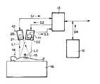
以下、図面を参照して本発明の実施の形態を詳細に説明する。図1は、本発明の外科手術支援システムの一つの実施の形態を示すものである。この外科手術支援システムは、蛍光像撮像装置10と、画像投影装置11と、MRI(磁気共鳴イメージング)装置12と、以上の各装置10、11および12に接続された制御装置13とから構成されている。
【0011】
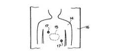
外科手術を受ける患者14の患部15には、腫瘍親和性を有し、光により励起されたとき蛍光を発する光感受性物質が予め吸収されている。この光感受性物質としては、例えばポルフィリン系のものが用いられる。なお図2に平面視の状態を示すように、患者14は手術台16上の所定位置に載置され、この患者14上の所定位置には一例として2個の位置合わせ蛍光マーカー17、17が固定されている。
【0012】
蛍光像撮像装置10は、上記光感受性物質の励起波長領域にある励起光L1を発する励起光源20と、上記光感受性物質が発する蛍光L2を検出して患部15の蛍光像を撮像する撮像手段21とから構成されている。なおこの撮像手段21は、例えば高感度のCCDカメラ等からなる。
【0013】
一方画像投影装置11は、例えば液晶表示パネル等の画像再生手段と、そこに再生表示された画像を患者14の患部15上に投影する投影光学系とから構成されている。そしてこの画像投影装置11には、上記位置合わせ蛍光マーカー17、17および制御装置13とともに画像位置合わせ手段を構成する、CCDカメラ等の撮像手段22が固定されている。
【0014】
以下、上記構成の外科手術支援システムの作用について説明する。患部15から腫瘍を摘出する外科手術が施される際には、蛍光像撮像装置10の励起光源20が駆動され、そこから発せられた励起光L1が患部15に照射される。それにより、患部15が吸収している光感受性物質が励起されて蛍光L2を発する。撮像手段21はこの蛍光L2を検出して患部15の蛍光像を撮像し、この蛍光像を示す画像データS1を制御装置13に入力する。
【0015】
制御装置13はこの画像データS1に対して、後述の位置合わせのための変換処理を施し、変換処理後の画像データS2を画像投影装置11に入力する。画像投影装置11はこの画像データS2に基づいて、前述した液晶表示パネル等の画像再生手段に患部15の蛍光像を再生表示する。図3の(a)は、この蛍光像の表示状態を概略的に示すものである。このように画像再生手段11aには、患部15に存在する腫瘍の像18Aを明瞭に示す蛍光像が表示される。なお図中の17Aは、マーカー像である。そして画像投影装置11は、この表示された蛍光像を、実際の患部15上に投影する。
【0016】
図3の(b)は、実際の患部15を肉眼で観察した状態を示している。実際の患部15には、上記蛍光像において示された腫瘍18が当然存在するものであるが、先に述べたよう手術室内が暗い等の理由で、肉眼ではこの腫瘍18が明瞭に認められないこともあり得る。しかしここで、上記蛍光像が、そこに示されている患部と実際の患部15とが位置的に整合するようにして実際の患部15上に投影されると、図3の(c)に示すように、実際に腫瘍18が存在する患部15上の位置に、腫瘍像18Aが投影表示されるようになる。
【0017】
したがって術者は、この投影表示画像中の腫瘍像18Aを参考にして、実際の腫瘍18の存在位置や大きさを正確に認識可能となり、よって、切除範囲を必要最小限にして適切な外科手術を行なうことができる。
【0018】
次に、実際の患部15と蛍光像との位置合わせについて説明する。画像投影装置11に固定されている撮像手段22は、実際の患部15を位置合わせ蛍光マーカー17、17とともに撮像する。こうして撮像された位置合わせ用画像を示す画像データS3は、制御装置13に入力される。制御装置13は、この画像データS3における蛍光マーカー17、17の画素位置と、蛍光像撮像装置10から入力された画像データS1における蛍光マーカー17、17の画素位置とが一致するように、画像データS1に対して画像拡縮および画像回転の変換処理を施す。
【0019】
また、画像投影装置11と撮像手段22との相対位置は、上記画像データS1とS3における蛍光マーカー17、17の画素位置が互いに一致したとき、実際の患部15と投影画像における患部とが位置的に整合するように設定されている。そこで、画像投影装置11により、上記変換処理を受けた後の画像データS2に基づいて蛍光像を再生し、それを実際の患部15上に投影すれば、実際に腫瘍18が存在する患部15上の位置に、腫瘍像18Aが投影表示されることになる。
【0020】
なお、画像データS1に対する画像拡縮(投影倍率変更)および画像回転(投影画像の向きの変更)の処理は、例えば蛍光像投影の向きを厳密に所定方向に設定可能である場合には画像拡縮のみというように、一方だけを行なうようにしてもよい。
【0021】
本例では、MRI装置12が出力するMRI画像データS4も制御装置13に入力されるようになっており、前記蛍光像に代えて、該画像データS4が示す患部15のMRI画像を実際の患部15上に投影表示可能となっている。したがって術者は、このMRI画像を参考にして病変部の位置を認識することもできる。この場合の表示画像における患部と実際の患部との位置合わせは、上に述べたのと同様にして行なうことができる。また、特に前述の蛍光マーカー17、17を写し込まなかったMRI画像に対しては、従来から知られているパターン・マッチングの手法を用いる等して、位置合わせを行なうことも可能である。
【0023】
また、蛍光像撮像装置10や画像投影装置11は、手術用照明装置や手術用顕微鏡装置に組み込むことができる。さらに画像投影装置11に代えて、光ビームを患部上で走査させてそこに画像を表示する装置を用いることもできる。
【図面の簡単な説明】
【図1】本発明の一つの実施の形態による外科手術支援システムを示す概略図
【図2】蛍光像撮像を受ける患者の状態を示す平面図
【図3】上記外科手術支援システムにおける患部画像の表示状態を説明する概略図
【符号の説明】
10 蛍光像撮像装置
11 画像投影装置
12 MRI装置
13 制御装置
14 患者
15 患部
17 位置合わせ蛍光マーカー
20 励起光源
21、22 撮像手段
L1 励起光
L2 蛍光[0001]
TECHNICAL FIELD OF THE INVENTION
BACKGROUND OF THE INVENTION 1. Field of the Invention The present invention relates to a surgical operation support system that assists an operator in confirming the position of a diseased part of a living body during a surgical operation.
[0002]
[Prior art]
2. Description of the Related Art Conventionally, various studies have been made on a photodynamic diagnosis generally called PDD (Photodynamic Diagnosis). The PDD means that a photosensitizer having tumor affinity and emitting fluorescence when excited by light is previously absorbed in a tumor part of a living body, and the excitation light in the excitation wavelength region of the photosensitizer is applied to the part. Is irradiated to generate fluorescence, and an image based on the fluorescence is displayed to diagnose a tumor portion.
[0003]
For example, Japanese Patent Publication No. 63-9644, Japanese Patent Application Laid-Open No. 1-136630, and Japanese Patent Application Laid-Open No. 7-59783 disclose a fluorescent image pickup apparatus for performing this PDD. Basically, this type of fluorescent image pickup device is an excitation light irradiating means for irradiating a living body with excitation light in an excitation wavelength region of a photosensitive substance, and a fluorescent image of a living body by detecting fluorescence emitted from the photosensitive substance. Means for capturing an image of the subject, and is often configured in a form incorporated in an endoscope inserted into a living body, a surgical microscope, or the like.
[0004]
When the image of the affected part captured by the above-described fluorescent image capturing apparatus is displayed on the image display means, the infiltration range of the tumor is shown as a fluorescent image because the photosensitizer has tumor affinity. Therefore, the surgeon can refer to this display image to grasp the invasion range of the tumor and determine an appropriate resection range.
[0005]
[Problems to be solved by the invention]
By the way, the fluorescence emitted from the above-mentioned photosensitizer is generally extremely weak. Therefore, when a fluorescence image is captured by a fluorescence image capturing device incorporated in a surgical microscope or the like, the brightness in the operating room is extremely low. It is necessary to lower it. If the operating room is darkened in this way, it is difficult to see the actual affected part, so even if the tumor part is displayed as a fluorescent image as described above, it is difficult to determine where it is located in the actual affected part. Become.
[0006]
Furthermore, since the fluorescent image displayed on the image display means is quite different from the actual affected part seen by the human eye, especially when the operator is unfamiliar, even if the operating room is bright, the fluorescent image It is difficult to understand the positional correspondence between the actual diseased part and the tumor, and it may not be possible to determine where the tumor part shown in the fluorescence image is located in the actual diseased part.
[0007]
The present invention has been made in view of the above circumstances, and it is an object of the present invention to provide a surgical operation support system capable of assisting an operator in confirming the position of a diseased part of a living body during a surgical operation. It is.
[0008]
[Means for Solving the Problems]
The surgical operation support system according to the present invention includes:
Irradiating the affected part of the living body undergoingthe surgical operation withthe excitation light in the excitation wavelength region of thephotosensitive substance, which absorbs the photosensitizer that emitsfluorescence, and detects the fluorescence emitted from the affected part at that time. Afluorescent image capturing apparatusthat captures a fluorescent image of the affected area, and outputs image data indicating thefluorescent imagewithout reconstructing the image ;
An image display device that reproduces afluorescent image of the affected part based on the image data and displays the image on the actual affected part;
The actual diseased part and a positioning means for adjusting the magnification and / or orientation of the displayedfluorescent image so that the diseased part in the displayedfluorescent image is aligned with each other.
[0009]
【The invention's effect】
According to the surgical operation support system of the present invention having the above configuration, an image of a diseased part of a living body is displayed on the actual diseased part after having a positional correspondence with the actual diseased part. Therefore, if a lesion is shown in the displayed image, it is superimposed and displayed on the actual lesion, so that the operator can easily and accurately recognize the position of the lesion.
[0010]
BEST MODE FOR CARRYING OUT THE INVENTION
Hereinafter, embodiments of the present invention will be described in detail with reference to the drawings. FIG. 1 shows an embodiment of a surgical operation support system according to the present invention. This surgical operation support system includes a fluorescent
[0011]
The affected
[0012]
The fluorescence
[0013]
On the other hand, the image projection device 11 is composed of an image reproducing means such as a liquid crystal display panel and a projection optical system for projecting the image reproduced and displayed on the affected
[0014]
Hereinafter, the operation of the surgical operation support system having the above configuration will be described. When a surgical operation for removing a tumor from the affected
[0015]
The
[0016]
FIG. 3B shows a state in which the actual
[0017]
Therefore, the surgeon can accurately recognize the actual location and size of the
[0018]
Next, the actual positioning of the
[0019]
When the pixel positions of the
[0020]
The processing of image enlargement / reduction (change of the projection magnification) and image rotation (change of the direction of the projection image) on the image data S1 is performed only when the fluorescence image projection direction can be strictly set to a predetermined direction. Thus, only one of them may be performed.
[0021]
In this example, the MRI image data S4 output from the MRI apparatus 12 is also input to the
[0023]
Further, the fluorescent
[Brief description of the drawings]
FIG. 1 is a schematic diagram showing a surgical operation support system according to one embodiment of the present invention. FIG. 2 is a plan view showing a state of a patient who receives a fluorescent image. FIG. 3 is a view showing an affected part image in the surgical operation support system. Schematic diagram for explaining the display state [Description of reference numerals]
DESCRIPTION OF
Claims (1)
Translated fromJapaneseこの画像データに基づいて前記患部の蛍光像を再生し、実際の患部上に表示する画像表示装置と、
実際の患部と、前記表示される蛍光像における患部とが互いに位置的に整合するように、表示される蛍光像の倍率および/または向きを調節する位置合わせ手段とからなる外科手術支援システム。Irradiating the affected part of the living body undergoingthe surgical operation withthe excitation light in the excitation wavelength region of thephotosensitive substance, which absorbs the photosensitizer that emitsfluorescence, and detects the fluorescence emitted from the affected part at that time. Afluorescent image capturing apparatusthat captures a fluorescent image of the affected area, and outputs image data indicating thefluorescent imagewithout reconstructing the image ;
An image display device that reproduces thefluorescent image of the affected part based on the image data and displays the image on the actual affected part,
A surgical operation support system comprising a positioning unit for adjusting a magnification and / or a direction of a displayedfluorescent image so that an actual diseased part and a diseased part in the displayedfluorescent image are aligned with each other.
Priority Applications (2)
| Application Number | Priority Date | Filing Date | Title |
|---|---|---|---|
| JP17599695AJP3568280B2 (en) | 1995-07-12 | 1995-07-12 | Surgical operation support system |
| US08/678,265US5772593A (en) | 1995-07-12 | 1996-07-11 | Surgical operation aiding system |
Applications Claiming Priority (2)
| Application Number | Priority Date | Filing Date | Title |
|---|---|---|---|
| JP17599695AJP3568280B2 (en) | 1995-07-12 | 1995-07-12 | Surgical operation support system |
| US08/678,265US5772593A (en) | 1995-07-12 | 1996-07-11 | Surgical operation aiding system |
Publications (2)
| Publication Number | Publication Date |
|---|---|
| JPH0924053A JPH0924053A (en) | 1997-01-28 |
| JP3568280B2true JP3568280B2 (en) | 2004-09-22 |
Family
ID=26497074
Family Applications (1)
| Application Number | Title | Priority Date | Filing Date |
|---|---|---|---|
| JP17599695AExpired - Fee RelatedJP3568280B2 (en) | 1995-07-12 | 1995-07-12 | Surgical operation support system |
Country Status (2)
| Country | Link |
|---|---|
| US (1) | US5772593A (en) |
| JP (1) | JP3568280B2 (en) |
Cited By (4)
| Publication number | Priority date | Publication date | Assignee | Title |
|---|---|---|---|---|
| KR101201083B1 (en) | 2011-06-15 | 2012-11-13 | 국립암센터 | Medical Multiple Clips, Clip Gun applying the same, Clipping Method using the same |
| KR101263939B1 (en) | 2011-12-02 | 2013-05-13 | 국립암센터 | Fluorescent indication clip for surgery |
| US10524666B2 (en) | 2018-05-09 | 2020-01-07 | Inner Ray, Inc. | White excitation light generating device and white excitation light generating method |
| US11442254B2 (en) | 2019-04-05 | 2022-09-13 | Inner Ray, Inc. | Augmented reality projection device |
Families Citing this family (103)
| Publication number | Priority date | Publication date | Assignee | Title |
|---|---|---|---|---|
| US6296613B1 (en) | 1997-08-22 | 2001-10-02 | Synthes (U.S.A.) | 3D ultrasound recording device |
| ES2304794T3 (en) | 1998-06-22 | 2008-10-16 | Ao Technology Ag | PAREO OF LOCATION THROUGH LOCALIZATION SCREWS. |
| CA2367271C (en) | 1999-03-17 | 2008-12-16 | Synthes (U.S.A.) | System and method for ligament graft placement |
| AU766981B2 (en) | 1999-04-20 | 2003-10-30 | Ao Technology Ag | Device for the percutaneous obtainment of 3D-coordinates on the surface of a human or animal organ |
| AU768975B2 (en)* | 1999-05-03 | 2004-01-15 | Ao Technology Ag | Position detector with auxiliary means for detecting the direction of the gravity vector |
| US6314311B1 (en)* | 1999-07-28 | 2001-11-06 | Picker International, Inc. | Movable mirror laser registration system |
| US6317616B1 (en) | 1999-09-15 | 2001-11-13 | Neil David Glossop | Method and system to facilitate image guided surgery |
| IL132138A0 (en)* | 1999-09-29 | 2001-03-19 | Metranets Ltd | Method and apparatus for 3d scanning of the human body form |
| DE60028815T2 (en) | 1999-12-23 | 2006-10-05 | Hill-Rom Services, Inc., Wilmington | OPERATING ROOM SYSTEM |
| US7239909B2 (en)* | 2000-01-19 | 2007-07-03 | Luminetx Technologies Corp. | Imaging system using diffuse infrared light |
| US8494616B2 (en)* | 2000-01-19 | 2013-07-23 | Christie Medical Holdings, Inc. | Method and apparatus for projection of subsurface structure onto an object's surface |
| US6556858B1 (en)* | 2000-01-19 | 2003-04-29 | Herbert D. Zeman | Diffuse infrared light imaging system |
| US8078263B2 (en)* | 2000-01-19 | 2011-12-13 | Christie Medical Holdings, Inc. | Projection of subsurface structure onto an object's surface |
| US20070161906A1 (en)* | 2000-01-19 | 2007-07-12 | Luminetx Technologies Corporation | Method To Facilitate A Dermatological Procedure |
| GB0014059D0 (en)* | 2000-06-09 | 2000-08-02 | Chumas Paul D | Method and apparatus |
| DE10033723C1 (en)* | 2000-07-12 | 2002-02-21 | Siemens Ag | Surgical instrument position and orientation visualization device for surgical operation has data representing instrument position and orientation projected onto surface of patient's body |
| US7547307B2 (en) | 2001-02-27 | 2009-06-16 | Smith & Nephew, Inc. | Computer assisted knee arthroplasty instrumentation, systems, and processes |
| WO2002080773A1 (en)* | 2001-04-05 | 2002-10-17 | Johns Hopkins University | Augmentet reality apparatus and ct method |
| JP2005516724A (en) | 2002-02-11 | 2005-06-09 | スミス アンド ネフュー インコーポレーテッド | Image guided fracture reduction |
| WO2004000151A1 (en)* | 2002-06-25 | 2003-12-31 | Michael Nicholas Dalton | Apparatus and method for superimposing images over an object |
| DE10238011A1 (en)* | 2002-08-20 | 2004-03-11 | GfM Gesellschaft für Medizintechnik mbH | Semi transparent augmented reality projection screen has pivoted arm to place image over hidden object and integral lighting |
| US7111401B2 (en)* | 2003-02-04 | 2006-09-26 | Eveready Battery Company, Inc. | Razor head having skin controlling means |
| US7862570B2 (en) | 2003-10-03 | 2011-01-04 | Smith & Nephew, Inc. | Surgical positioners |
| US7764985B2 (en) | 2003-10-20 | 2010-07-27 | Smith & Nephew, Inc. | Surgical navigation system component fault interfaces and related processes |
| ATE495706T1 (en) | 2003-11-14 | 2011-02-15 | Smith & Nephew Inc | ADJUSTABLE SURGICAL CUTTING SYSTEMS |
| JP4578817B2 (en)* | 2004-02-06 | 2010-11-10 | オリンパス株式会社 | Surgical lesion identification system |
| US7567833B2 (en)* | 2004-03-08 | 2009-07-28 | Stryker Leibinger Gmbh & Co. Kg | Enhanced illumination device and method |
| CA2561493A1 (en) | 2004-03-31 | 2005-10-20 | Smith & Nephew, Inc. | Methods and apparatuses for providing a reference array input device |
| EP1737375B1 (en) | 2004-04-21 | 2021-08-11 | Smith & Nephew, Inc | Computer-aided navigation systems for shoulder arthroplasty |
| US20080162213A1 (en)* | 2004-06-14 | 2008-07-03 | Clayton James D | Decision object for associating a plurality of business plans |
| US8548570B2 (en) | 2004-11-29 | 2013-10-01 | Hypermed Imaging, Inc. | Hyperspectral imaging of angiogenesis |
| EP2319406A1 (en)* | 2004-12-28 | 2011-05-11 | Hyperspectral Imaging, Inc | Hyperspectral/multispectral imaging in determination, assessment and monitoring of systemic physiology and shock |
| WO2006091704A1 (en) | 2005-02-22 | 2006-08-31 | Smith & Nephew, Inc. | In-line milling system |
| EP1695670A1 (en)* | 2005-02-24 | 2006-08-30 | BrainLAB AG | Portable Laser projection device for the medical image presentation |
| US9204116B2 (en)* | 2005-02-24 | 2015-12-01 | Brainlab Ag | Portable laser projection device for medical image display |
| CA2947613C (en) | 2005-04-04 | 2019-11-05 | Hypermed Imaging, Inc. | Hyperspectral imaging in diabetes and peripheral vascular disease |
| DE602005024873D1 (en)* | 2005-07-01 | 2010-12-30 | Luminetx Corp | PROJECTION OF A SURFACE STRUCTURE ON THE SURFACE OF AN OBJECT |
| US20070025521A1 (en)* | 2005-07-14 | 2007-02-01 | Tommi Jokiniemi | Method and equipment arrangement for presenting information in radiology |
| DE102005060311A1 (en)* | 2005-12-16 | 2007-06-21 | Siemens Ag | Device for visualizing object properties |
| US8478386B2 (en) | 2006-01-10 | 2013-07-02 | Accuvein Inc. | Practitioner-mounted micro vein enhancer |
| US11278240B2 (en) | 2006-01-10 | 2022-03-22 | Accuvein, Inc. | Trigger-actuated laser vein contrast enhancer |
| US8838210B2 (en) | 2006-06-29 | 2014-09-16 | AccuView, Inc. | Scanned laser vein contrast enhancer using a single laser |
| US10813588B2 (en) | 2006-01-10 | 2020-10-27 | Accuvein, Inc. | Micro vein enhancer |
| US8489178B2 (en) | 2006-06-29 | 2013-07-16 | Accuvein Inc. | Enhanced laser vein contrast enhancer with projection of analyzed vein data |
| US9854977B2 (en) | 2006-01-10 | 2018-01-02 | Accuvein, Inc. | Scanned laser vein contrast enhancer using a single laser, and modulation circuitry |
| US11253198B2 (en) | 2006-01-10 | 2022-02-22 | Accuvein, Inc. | Stand-mounted scanned laser vein contrast enhancer |
| US10238294B2 (en) | 2006-06-29 | 2019-03-26 | Accuvein, Inc. | Scanned laser vein contrast enhancer using one laser |
| US12408865B2 (en) | 2006-01-10 | 2025-09-09 | Accuvein Inc. | Vein imaging device with differential image resolution at the center and the extremities of the vein image |
| US8255040B2 (en)* | 2006-06-29 | 2012-08-28 | Accuvein, Llc | Micro vein enhancer |
| US9492117B2 (en) | 2006-01-10 | 2016-11-15 | Accuvein, Inc. | Practitioner-mounted micro vein enhancer |
| US12089951B2 (en) | 2006-01-10 | 2024-09-17 | AccuVeiw, Inc. | Scanned laser vein contrast enhancer with scanning correlated to target distance |
| US12295744B2 (en) | 2006-01-10 | 2025-05-13 | Accuvein, Inc. | Micro vein enhancer with two lasers and two optical detectors configured for removing surface topology |
| US8442281B2 (en)* | 2006-04-28 | 2013-05-14 | The Invention Science Fund I, Llc | Artificially displaying information relative to a body |
| JP4699295B2 (en)* | 2006-06-19 | 2011-06-08 | 株式会社吉田製作所 | Dental display device |
| US8665507B2 (en)* | 2006-06-29 | 2014-03-04 | Accuvein, Inc. | Module mounting mirror endoscopy |
| US8730321B2 (en) | 2007-06-28 | 2014-05-20 | Accuvein, Inc. | Automatic alignment of a contrast enhancement system |
| US8463364B2 (en)* | 2009-07-22 | 2013-06-11 | Accuvein Inc. | Vein scanner |
| US20160296146A9 (en)* | 2006-06-29 | 2016-10-13 | Fred Wood | Apparatus-Mounted Vein Contrast Enchancer |
| US8594770B2 (en) | 2006-06-29 | 2013-11-26 | Accuvein, Inc. | Multispectral detection and presentation of an object's characteristics |
| US8244333B2 (en)* | 2006-06-29 | 2012-08-14 | Accuvein, Llc | Scanned laser vein contrast enhancer |
| US20080004533A1 (en)* | 2006-06-30 | 2008-01-03 | General Electric Company | Optical imaging systems and methods |
| ATE479398T1 (en)* | 2006-09-11 | 2010-09-15 | Koninkl Philips Electronics Nv | SYSTEM AND METHOD FOR POSITIONING ELECTRODES ON A PATIENT'S BODY |
| WO2008101129A1 (en)* | 2007-02-14 | 2008-08-21 | Luminetx Corporation | System and method for projection of subsurface structure onto an object's surface |
| EP2075616A1 (en)* | 2007-12-28 | 2009-07-01 | Möller-Wedel GmbH | Device with a camera and a device for mapping and projecting the picture taken |
| GB2457072A (en)* | 2008-02-01 | 2009-08-05 | Elekta Ab | Fluorescence vision system |
| US20090236541A1 (en)* | 2008-03-24 | 2009-09-24 | General Electric Company | System and Methods for Optical Imaging |
| AU2009246917A1 (en) | 2008-05-13 | 2009-11-19 | Spectral Image, Inc. | Systems and methods for hyperspectral medical imaging using real-time projection of spectral information |
| US20090318815A1 (en)* | 2008-05-23 | 2009-12-24 | Michael Barnes | Systems and methods for hyperspectral medical imaging |
| US9117133B2 (en) | 2008-06-18 | 2015-08-25 | Spectral Image, Inc. | Systems and methods for hyperspectral imaging |
| WO2010056945A2 (en)* | 2008-11-13 | 2010-05-20 | Shalon Ventures, Inc. | Methods and systems for tissue processing and imaging |
| KR101263937B1 (en) | 2009-06-29 | 2013-05-13 | 국립암센터 | Fluorescent indication clip for surgery |
| US9061109B2 (en) | 2009-07-22 | 2015-06-23 | Accuvein, Inc. | Vein scanner with user interface |
| DE102009040430B4 (en)* | 2009-09-07 | 2013-03-07 | Fraunhofer-Gesellschaft zur Förderung der angewandten Forschung e.V. | Apparatus, method and computer program for overlaying an intra-operative live image of an operating area or the operating area with a preoperative image of the operating area |
| US8579922B2 (en)* | 2009-10-05 | 2013-11-12 | Covidien Lp | Method of suture identification and mesh marking for orienting and locating a mesh during hernia repair |
| US8504136B1 (en)* | 2009-10-06 | 2013-08-06 | University Of South Florida | See-through abdomen display for minimally invasive surgery |
| US8605165B2 (en)* | 2010-10-06 | 2013-12-10 | Ai Cure Technologies Llc | Apparatus and method for assisting monitoring of medication adherence |
| CN102770071B (en) | 2009-12-15 | 2015-03-25 | 爱默蕾大学 | Systems and methods for providing real-time anatomical guidance during diagnostic or therapeutic procedures |
| JP2013515266A (en)* | 2009-12-21 | 2013-05-02 | テルモ株式会社 | Excitation / detection / projection system to visualize target cancer tissue |
| JP2012115535A (en)* | 2010-12-02 | 2012-06-21 | Kochi Univ | Medical implement that emits near-infrared fluorescence and medical implement position confirmation system |
| EP2500816B1 (en) | 2011-03-13 | 2018-05-16 | LG Electronics Inc. | Transparent display apparatus and method for operating the same |
| US20130041266A1 (en)* | 2011-08-12 | 2013-02-14 | Tyco Healthcare Group Lp, | System and Method for Indicating Positioning of an Internal Anatomical Feature |
| US9520072B2 (en)* | 2011-09-21 | 2016-12-13 | University Of South Florida | Systems and methods for projecting images onto an object |
| CA2858578A1 (en)* | 2011-12-19 | 2013-06-27 | Howard L. Shackelford | Anatomical orientation system |
| US8971989B2 (en) | 2012-01-24 | 2015-03-03 | Covidien Lp | Magnetic field device for mapping and navigation in laparoscopic surgery |
| DE102012206350A1 (en)* | 2012-04-18 | 2013-10-24 | Deutsches Zentrum für Luft- und Raumfahrt e.V. | Method for operating a robot |
| US9072426B2 (en) | 2012-08-02 | 2015-07-07 | AccuVein, Inc | Device for detecting and illuminating vasculature using an FPGA |
| US10517483B2 (en) | 2012-12-05 | 2019-12-31 | Accuvein, Inc. | System for detecting fluorescence and projecting a representative image |
| TWI586327B (en)* | 2012-12-27 | 2017-06-11 | Metal Ind Research&Development Centre | Image projection system |
| AU2014236561B2 (en) | 2013-03-14 | 2018-08-16 | Lumicell, Inc. | Medical imaging device and methods of use |
| WO2015001807A1 (en) | 2013-07-05 | 2015-01-08 | パナソニックIpマネジメント株式会社 | Projection system |
| JPWO2015072047A1 (en) | 2013-11-14 | 2017-03-16 | パナソニックIpマネジメント株式会社 | Projection system |
| JP5915949B2 (en) | 2014-06-25 | 2016-05-11 | パナソニックIpマネジメント株式会社 | Projection system |
| WO2015198578A1 (en) | 2014-06-25 | 2015-12-30 | パナソニックIpマネジメント株式会社 | Projection system |
| JP6480694B2 (en) | 2014-09-30 | 2019-03-13 | 京セラ株式会社 | Surgery support device and program |
| JP6176582B2 (en) | 2015-03-31 | 2017-08-09 | パナソニックIpマネジメント株式会社 | Visible light projector |
| DE112016006140T5 (en)* | 2016-02-29 | 2018-09-13 | Olympus Corporation | Imaging / projection device with optical scanning and endoscope system |
| WO2017164101A1 (en)* | 2016-03-22 | 2017-09-28 | 国立研究開発法人産業技術総合研究所 | Light radiation system, control device, light radiation control method, and surgical microscope device |
| EP3424458B1 (en) | 2017-07-07 | 2020-11-11 | Leica Instruments (Singapore) Pte. Ltd. | Apparatus and method for tracking a movable target |
| CN109247910B (en)* | 2017-07-12 | 2020-12-15 | 京东方科技集团股份有限公司 | Blood vessel display device and blood vessel display method |
| WO2019103052A1 (en) | 2017-11-27 | 2019-05-31 | パナソニック株式会社 | Projection device |
| JPWO2019194174A1 (en)* | 2018-04-03 | 2021-05-13 | 国立大学法人京都大学 | Medical projector |
| JP2019184707A (en) | 2018-04-04 | 2019-10-24 | パナソニック株式会社 | Image projection device |
| US20210298863A1 (en)* | 2020-03-27 | 2021-09-30 | Trumpf Medizin Systeme GmbH & Co. KG. | Augmented reality for a surgical system |
Family Cites Families (4)
| Publication number | Priority date | Publication date | Assignee | Title |
|---|---|---|---|---|
| CH663902A5 (en)* | 1986-06-27 | 1988-01-29 | Heinz Donnerstag | STRENGTH TRAINING EQUIPMENT FOR SKIERS AND ICE SKATER. |
| JPH01136630A (en)* | 1987-11-25 | 1989-05-29 | Olympus Optical Co Ltd | Endoscopic apparatus for fluorescent observation |
| US5526812A (en)* | 1993-06-21 | 1996-06-18 | General Electric Company | Display system for enhancing visualization of body structures during medical procedures |
| JP3221169B2 (en)* | 1993-08-26 | 2001-10-22 | 松下電器産業株式会社 | Cancer lesion diagnostic device |
- 1995
- 1995-07-12JPJP17599695Apatent/JP3568280B2/ennot_activeExpired - Fee Related
- 1996
- 1996-07-11USUS08/678,265patent/US5772593A/ennot_activeExpired - Fee Related
Cited By (4)
| Publication number | Priority date | Publication date | Assignee | Title |
|---|---|---|---|---|
| KR101201083B1 (en) | 2011-06-15 | 2012-11-13 | 국립암센터 | Medical Multiple Clips, Clip Gun applying the same, Clipping Method using the same |
| KR101263939B1 (en) | 2011-12-02 | 2013-05-13 | 국립암센터 | Fluorescent indication clip for surgery |
| US10524666B2 (en) | 2018-05-09 | 2020-01-07 | Inner Ray, Inc. | White excitation light generating device and white excitation light generating method |
| US11442254B2 (en) | 2019-04-05 | 2022-09-13 | Inner Ray, Inc. | Augmented reality projection device |
Also Published As
| Publication number | Publication date |
|---|---|
| JPH0924053A (en) | 1997-01-28 |
| US5772593A (en) | 1998-06-30 |
Similar Documents
| Publication | Publication Date | Title |
|---|---|---|
| JP3568280B2 (en) | Surgical operation support system | |
| JP3532368B2 (en) | Endoscope | |
| JP3394447B2 (en) | Fluorescent endoscope | |
| US20030078477A1 (en) | Fluorescence endoscope apparatus and method for imaging tissue within a body using the same | |
| JPH10309281A (en) | Fluorescent diagnostic device | |
| WO2015092882A1 (en) | Infrared light imaging apparatus | |
| US10413619B2 (en) | Imaging device | |
| JP2009022652A (en) | Endoscope light source device | |
| JP4610970B2 (en) | Detachable filter device and endoscope device | |
| EP3435831A1 (en) | Imaging apparatus, imaging method, and medical observation equipment | |
| CN107072643A (en) | Imaging device | |
| JP2001149317A (en) | Fundus imaging device | |
| JP4648683B2 (en) | Endoscope system | |
| JP2008043383A (en) | Fluorescence observation endoscope device | |
| EP1227686B1 (en) | Feeble light color imaging device | |
| JP3221169B2 (en) | Cancer lesion diagnostic device | |
| JPH0663164A (en) | Laser irradiation device | |
| JP6747576B2 (en) | Imaging equipment | |
| JPH01136629A (en) | Endoscopic apparatus for fluorescent observation | |
| JP3380119B2 (en) | Endoscope device for fluorescence diagnosis | |
| JP2009022653A (en) | Electronic endoscope system | |
| WO2017169335A1 (en) | Imaging apparatus, imaging method, and medical observation equipment | |
| CN1119972C (en) | Coaxle low-light fluorescent diagnosing and positioning instrument for cancer of lung | |
| JP2005049282A (en) | Fluorescent observation apparatus and laser light irradiation device | |
| JP3638275B2 (en) | Ophthalmic image processing system |
Legal Events
| Date | Code | Title | Description |
|---|---|---|---|
| TRDD | Decision of grant or rejection written | ||
| A01 | Written decision to grant a patent or to grant a registration (utility model) | Free format text:JAPANESE INTERMEDIATE CODE: A01 Effective date:20040615 | |
| A61 | First payment of annual fees (during grant procedure) | Free format text:JAPANESE INTERMEDIATE CODE: A61 Effective date:20040615 | |
| R150 | Certificate of patent or registration of utility model | Free format text:JAPANESE INTERMEDIATE CODE: R150 | |
| R250 | Receipt of annual fees | Free format text:JAPANESE INTERMEDIATE CODE: R250 | |
| S111 | Request for change of ownership or part of ownership | Free format text:JAPANESE INTERMEDIATE CODE: R313111 | |
| FPAY | Renewal fee payment (event date is renewal date of database) | Free format text:PAYMENT UNTIL: 20080625 Year of fee payment:4 | |
| R350 | Written notification of registration of transfer | Free format text:JAPANESE INTERMEDIATE CODE: R350 | |
| FPAY | Renewal fee payment (event date is renewal date of database) | Free format text:PAYMENT UNTIL: 20080625 Year of fee payment:4 | |
| FPAY | Renewal fee payment (event date is renewal date of database) | Free format text:PAYMENT UNTIL: 20090625 Year of fee payment:5 | |
| FPAY | Renewal fee payment (event date is renewal date of database) | Free format text:PAYMENT UNTIL: 20090625 Year of fee payment:5 | |
| FPAY | Renewal fee payment (event date is renewal date of database) | Free format text:PAYMENT UNTIL: 20100625 Year of fee payment:6 | |
| FPAY | Renewal fee payment (event date is renewal date of database) | Free format text:PAYMENT UNTIL: 20100625 Year of fee payment:6 | |
| FPAY | Renewal fee payment (event date is renewal date of database) | Free format text:PAYMENT UNTIL: 20110625 Year of fee payment:7 | |
| FPAY | Renewal fee payment (event date is renewal date of database) | Free format text:PAYMENT UNTIL: 20110625 Year of fee payment:7 | |
| FPAY | Renewal fee payment (event date is renewal date of database) | Free format text:PAYMENT UNTIL: 20120625 Year of fee payment:8 | |
| FPAY | Renewal fee payment (event date is renewal date of database) | Free format text:PAYMENT UNTIL: 20120625 Year of fee payment:8 | |
| FPAY | Renewal fee payment (event date is renewal date of database) | Free format text:PAYMENT UNTIL: 20130625 Year of fee payment:9 | |
| R250 | Receipt of annual fees | Free format text:JAPANESE INTERMEDIATE CODE: R250 | |
| R250 | Receipt of annual fees | Free format text:JAPANESE INTERMEDIATE CODE: R250 | |
| LAPS | Cancellation because of no payment of annual fees |