JP3568210B2 - Control system for automatically dimming vehicle headlights - Google Patents
Control system for automatically dimming vehicle headlightsDownload PDFInfo
- Publication number
- JP3568210B2 JP3568210B2JP54179798AJP54179798AJP3568210B2JP 3568210 B2JP3568210 B2JP 3568210B2JP 54179798 AJP54179798 AJP 54179798AJP 54179798 AJP54179798 AJP 54179798AJP 3568210 B2JP3568210 B2JP 3568210B2
- Authority
- JP
- Japan
- Prior art keywords
- headlamp
- control system
- light source
- image
- control
- Prior art date
- Legal status (The legal status is an assumption and is not a legal conclusion. Google has not performed a legal analysis and makes no representation as to the accuracy of the status listed.)
- Expired - Lifetime
Links
Images


Classifications
- B—PERFORMING OPERATIONS; TRANSPORTING
- B60—VEHICLES IN GENERAL
- B60Q—ARRANGEMENT OF SIGNALLING OR LIGHTING DEVICES, THE MOUNTING OR SUPPORTING THEREOF OR CIRCUITS THEREFOR, FOR VEHICLES IN GENERAL
- B60Q1/00—Arrangement of optical signalling or lighting devices, the mounting or supporting thereof or circuits therefor
- B60Q1/02—Arrangement of optical signalling or lighting devices, the mounting or supporting thereof or circuits therefor the devices being primarily intended to illuminate the way ahead or to illuminate other areas of way or environments
- B60Q1/04—Arrangement of optical signalling or lighting devices, the mounting or supporting thereof or circuits therefor the devices being primarily intended to illuminate the way ahead or to illuminate other areas of way or environments the devices being headlights
- B60Q1/06—Arrangement of optical signalling or lighting devices, the mounting or supporting thereof or circuits therefor the devices being primarily intended to illuminate the way ahead or to illuminate other areas of way or environments the devices being headlights adjustable, e.g. remotely-controlled from inside vehicle
- B60Q1/08—Arrangement of optical signalling or lighting devices, the mounting or supporting thereof or circuits therefor the devices being primarily intended to illuminate the way ahead or to illuminate other areas of way or environments the devices being headlights adjustable, e.g. remotely-controlled from inside vehicle automatically
- B60Q1/085—Arrangement of optical signalling or lighting devices, the mounting or supporting thereof or circuits therefor the devices being primarily intended to illuminate the way ahead or to illuminate other areas of way or environments the devices being headlights adjustable, e.g. remotely-controlled from inside vehicle automatically due to special conditions, e.g. adverse weather, type of road, badly illuminated road signs or potential dangers
- H—ELECTRICITY
- H04—ELECTRIC COMMUNICATION TECHNIQUE
- H04N—PICTORIAL COMMUNICATION, e.g. TELEVISION
- H04N25/00—Circuitry of solid-state image sensors [SSIS]; Control thereof
- B—PERFORMING OPERATIONS; TRANSPORTING
- B60—VEHICLES IN GENERAL
- B60Q—ARRANGEMENT OF SIGNALLING OR LIGHTING DEVICES, THE MOUNTING OR SUPPORTING THEREOF OR CIRCUITS THEREFOR, FOR VEHICLES IN GENERAL
- B60Q1/00—Arrangement of optical signalling or lighting devices, the mounting or supporting thereof or circuits therefor
- B60Q1/0017—Devices integrating an element dedicated to another function
- B60Q1/0023—Devices integrating an element dedicated to another function the element being a sensor, e.g. distance sensor, camera
- B—PERFORMING OPERATIONS; TRANSPORTING
- B60—VEHICLES IN GENERAL
- B60Q—ARRANGEMENT OF SIGNALLING OR LIGHTING DEVICES, THE MOUNTING OR SUPPORTING THEREOF OR CIRCUITS THEREFOR, FOR VEHICLES IN GENERAL
- B60Q1/00—Arrangement of optical signalling or lighting devices, the mounting or supporting thereof or circuits therefor
- B60Q1/02—Arrangement of optical signalling or lighting devices, the mounting or supporting thereof or circuits therefor the devices being primarily intended to illuminate the way ahead or to illuminate other areas of way or environments
- B60Q1/04—Arrangement of optical signalling or lighting devices, the mounting or supporting thereof or circuits therefor the devices being primarily intended to illuminate the way ahead or to illuminate other areas of way or environments the devices being headlights
- B60Q1/14—Arrangement of optical signalling or lighting devices, the mounting or supporting thereof or circuits therefor the devices being primarily intended to illuminate the way ahead or to illuminate other areas of way or environments the devices being headlights having dimming means
- B60Q1/1415—Dimming circuits
- B60Q1/1423—Automatic dimming circuits, i.e. switching between high beam and low beam due to change of ambient light or light level in road traffic
- B60Q1/143—Automatic dimming circuits, i.e. switching between high beam and low beam due to change of ambient light or light level in road traffic combined with another condition, e.g. using vehicle recognition from camera images or activation of wipers
- B—PERFORMING OPERATIONS; TRANSPORTING
- B60—VEHICLES IN GENERAL
- B60Q—ARRANGEMENT OF SIGNALLING OR LIGHTING DEVICES, THE MOUNTING OR SUPPORTING THEREOF OR CIRCUITS THEREFOR, FOR VEHICLES IN GENERAL
- B60Q1/00—Arrangement of optical signalling or lighting devices, the mounting or supporting thereof or circuits therefor
- B60Q1/02—Arrangement of optical signalling or lighting devices, the mounting or supporting thereof or circuits therefor the devices being primarily intended to illuminate the way ahead or to illuminate other areas of way or environments
- B60Q1/04—Arrangement of optical signalling or lighting devices, the mounting or supporting thereof or circuits therefor the devices being primarily intended to illuminate the way ahead or to illuminate other areas of way or environments the devices being headlights
- B60Q1/18—Arrangement of optical signalling or lighting devices, the mounting or supporting thereof or circuits therefor the devices being primarily intended to illuminate the way ahead or to illuminate other areas of way or environments the devices being headlights being additional front lights
- G—PHYSICS
- G06—COMPUTING OR CALCULATING; COUNTING
- G06V—IMAGE OR VIDEO RECOGNITION OR UNDERSTANDING
- G06V20/00—Scenes; Scene-specific elements
- G06V20/50—Context or environment of the image
- G06V20/56—Context or environment of the image exterior to a vehicle by using sensors mounted on the vehicle
- G06V20/58—Recognition of moving objects or obstacles, e.g. vehicles or pedestrians; Recognition of traffic objects, e.g. traffic signs, traffic lights or roads
- G06V20/584—Recognition of moving objects or obstacles, e.g. vehicles or pedestrians; Recognition of traffic objects, e.g. traffic signs, traffic lights or roads of vehicle lights or traffic lights
- B—PERFORMING OPERATIONS; TRANSPORTING
- B60—VEHICLES IN GENERAL
- B60Q—ARRANGEMENT OF SIGNALLING OR LIGHTING DEVICES, THE MOUNTING OR SUPPORTING THEREOF OR CIRCUITS THEREFOR, FOR VEHICLES IN GENERAL
- B60Q2300/00—Indexing codes for automatically adjustable headlamps or automatically dimmable headlamps
- B60Q2300/05—Special features for controlling or switching of the light beam
- B60Q2300/054—Variable non-standard intensity, i.e. emission of various beam intensities different from standard intensities, e.g. continuous or stepped transitions of intensity
- B—PERFORMING OPERATIONS; TRANSPORTING
- B60—VEHICLES IN GENERAL
- B60Q—ARRANGEMENT OF SIGNALLING OR LIGHTING DEVICES, THE MOUNTING OR SUPPORTING THEREOF OR CIRCUITS THEREFOR, FOR VEHICLES IN GENERAL
- B60Q2300/00—Indexing codes for automatically adjustable headlamps or automatically dimmable headlamps
- B60Q2300/10—Indexing codes relating to particular vehicle conditions
- B60Q2300/11—Linear movements of the vehicle
- B60Q2300/112—Vehicle speed
- B—PERFORMING OPERATIONS; TRANSPORTING
- B60—VEHICLES IN GENERAL
- B60Q—ARRANGEMENT OF SIGNALLING OR LIGHTING DEVICES, THE MOUNTING OR SUPPORTING THEREOF OR CIRCUITS THEREFOR, FOR VEHICLES IN GENERAL
- B60Q2300/00—Indexing codes for automatically adjustable headlamps or automatically dimmable headlamps
- B60Q2300/10—Indexing codes relating to particular vehicle conditions
- B60Q2300/11—Linear movements of the vehicle
- B60Q2300/114—Vehicle acceleration or deceleration
- B—PERFORMING OPERATIONS; TRANSPORTING
- B60—VEHICLES IN GENERAL
- B60Q—ARRANGEMENT OF SIGNALLING OR LIGHTING DEVICES, THE MOUNTING OR SUPPORTING THEREOF OR CIRCUITS THEREFOR, FOR VEHICLES IN GENERAL
- B60Q2300/00—Indexing codes for automatically adjustable headlamps or automatically dimmable headlamps
- B60Q2300/10—Indexing codes relating to particular vehicle conditions
- B60Q2300/11—Linear movements of the vehicle
- B60Q2300/116—Vehicle at a stop
- B—PERFORMING OPERATIONS; TRANSPORTING
- B60—VEHICLES IN GENERAL
- B60Q—ARRANGEMENT OF SIGNALLING OR LIGHTING DEVICES, THE MOUNTING OR SUPPORTING THEREOF OR CIRCUITS THEREFOR, FOR VEHICLES IN GENERAL
- B60Q2300/00—Indexing codes for automatically adjustable headlamps or automatically dimmable headlamps
- B60Q2300/10—Indexing codes relating to particular vehicle conditions
- B60Q2300/12—Steering parameters
- B60Q2300/122—Steering angle
- B—PERFORMING OPERATIONS; TRANSPORTING
- B60—VEHICLES IN GENERAL
- B60Q—ARRANGEMENT OF SIGNALLING OR LIGHTING DEVICES, THE MOUNTING OR SUPPORTING THEREOF OR CIRCUITS THEREFOR, FOR VEHICLES IN GENERAL
- B60Q2300/00—Indexing codes for automatically adjustable headlamps or automatically dimmable headlamps
- B60Q2300/10—Indexing codes relating to particular vehicle conditions
- B60Q2300/13—Attitude of the vehicle body
- B60Q2300/132—Pitch
- B—PERFORMING OPERATIONS; TRANSPORTING
- B60—VEHICLES IN GENERAL
- B60Q—ARRANGEMENT OF SIGNALLING OR LIGHTING DEVICES, THE MOUNTING OR SUPPORTING THEREOF OR CIRCUITS THEREFOR, FOR VEHICLES IN GENERAL
- B60Q2300/00—Indexing codes for automatically adjustable headlamps or automatically dimmable headlamps
- B60Q2300/10—Indexing codes relating to particular vehicle conditions
- B60Q2300/13—Attitude of the vehicle body
- B60Q2300/134—Yaw
- B—PERFORMING OPERATIONS; TRANSPORTING
- B60—VEHICLES IN GENERAL
- B60Q—ARRANGEMENT OF SIGNALLING OR LIGHTING DEVICES, THE MOUNTING OR SUPPORTING THEREOF OR CIRCUITS THEREFOR, FOR VEHICLES IN GENERAL
- B60Q2300/00—Indexing codes for automatically adjustable headlamps or automatically dimmable headlamps
- B60Q2300/20—Indexing codes relating to the driver or the passengers
- B60Q2300/21—Manual control
- B—PERFORMING OPERATIONS; TRANSPORTING
- B60—VEHICLES IN GENERAL
- B60Q—ARRANGEMENT OF SIGNALLING OR LIGHTING DEVICES, THE MOUNTING OR SUPPORTING THEREOF OR CIRCUITS THEREFOR, FOR VEHICLES IN GENERAL
- B60Q2300/00—Indexing codes for automatically adjustable headlamps or automatically dimmable headlamps
- B60Q2300/30—Indexing codes relating to the vehicle environment
- B60Q2300/31—Atmospheric conditions
- B60Q2300/312—Adverse weather
- B—PERFORMING OPERATIONS; TRANSPORTING
- B60—VEHICLES IN GENERAL
- B60Q—ARRANGEMENT OF SIGNALLING OR LIGHTING DEVICES, THE MOUNTING OR SUPPORTING THEREOF OR CIRCUITS THEREFOR, FOR VEHICLES IN GENERAL
- B60Q2300/00—Indexing codes for automatically adjustable headlamps or automatically dimmable headlamps
- B60Q2300/30—Indexing codes relating to the vehicle environment
- B60Q2300/31—Atmospheric conditions
- B60Q2300/314—Ambient light
- B—PERFORMING OPERATIONS; TRANSPORTING
- B60—VEHICLES IN GENERAL
- B60Q—ARRANGEMENT OF SIGNALLING OR LIGHTING DEVICES, THE MOUNTING OR SUPPORTING THEREOF OR CIRCUITS THEREFOR, FOR VEHICLES IN GENERAL
- B60Q2300/00—Indexing codes for automatically adjustable headlamps or automatically dimmable headlamps
- B60Q2300/30—Indexing codes relating to the vehicle environment
- B60Q2300/32—Road surface or travel path
- B60Q2300/322—Road curvature
- B—PERFORMING OPERATIONS; TRANSPORTING
- B60—VEHICLES IN GENERAL
- B60Q—ARRANGEMENT OF SIGNALLING OR LIGHTING DEVICES, THE MOUNTING OR SUPPORTING THEREOF OR CIRCUITS THEREFOR, FOR VEHICLES IN GENERAL
- B60Q2300/00—Indexing codes for automatically adjustable headlamps or automatically dimmable headlamps
- B60Q2300/30—Indexing codes relating to the vehicle environment
- B60Q2300/32—Road surface or travel path
- B60Q2300/324—Road inclination, e.g. uphill or downhill
- B—PERFORMING OPERATIONS; TRANSPORTING
- B60—VEHICLES IN GENERAL
- B60Q—ARRANGEMENT OF SIGNALLING OR LIGHTING DEVICES, THE MOUNTING OR SUPPORTING THEREOF OR CIRCUITS THEREFOR, FOR VEHICLES IN GENERAL
- B60Q2300/00—Indexing codes for automatically adjustable headlamps or automatically dimmable headlamps
- B60Q2300/30—Indexing codes relating to the vehicle environment
- B60Q2300/33—Driving situation
- B60Q2300/332—Driving situation on city roads
- B60Q2300/3321—Detection of streetlights
- B—PERFORMING OPERATIONS; TRANSPORTING
- B60—VEHICLES IN GENERAL
- B60Q—ARRANGEMENT OF SIGNALLING OR LIGHTING DEVICES, THE MOUNTING OR SUPPORTING THEREOF OR CIRCUITS THEREFOR, FOR VEHICLES IN GENERAL
- B60Q2300/00—Indexing codes for automatically adjustable headlamps or automatically dimmable headlamps
- B60Q2300/30—Indexing codes relating to the vehicle environment
- B60Q2300/33—Driving situation
- B60Q2300/333—Driving situation on suburban or country roads
- B—PERFORMING OPERATIONS; TRANSPORTING
- B60—VEHICLES IN GENERAL
- B60Q—ARRANGEMENT OF SIGNALLING OR LIGHTING DEVICES, THE MOUNTING OR SUPPORTING THEREOF OR CIRCUITS THEREFOR, FOR VEHICLES IN GENERAL
- B60Q2300/00—Indexing codes for automatically adjustable headlamps or automatically dimmable headlamps
- B60Q2300/30—Indexing codes relating to the vehicle environment
- B60Q2300/33—Driving situation
- B60Q2300/337—Tunnels or bridges
- B—PERFORMING OPERATIONS; TRANSPORTING
- B60—VEHICLES IN GENERAL
- B60Q—ARRANGEMENT OF SIGNALLING OR LIGHTING DEVICES, THE MOUNTING OR SUPPORTING THEREOF OR CIRCUITS THEREFOR, FOR VEHICLES IN GENERAL
- B60Q2300/00—Indexing codes for automatically adjustable headlamps or automatically dimmable headlamps
- B60Q2300/40—Indexing codes relating to other road users or special conditions
- B60Q2300/41—Indexing codes relating to other road users or special conditions preceding vehicle
- B—PERFORMING OPERATIONS; TRANSPORTING
- B60—VEHICLES IN GENERAL
- B60Q—ARRANGEMENT OF SIGNALLING OR LIGHTING DEVICES, THE MOUNTING OR SUPPORTING THEREOF OR CIRCUITS THEREFOR, FOR VEHICLES IN GENERAL
- B60Q2300/00—Indexing codes for automatically adjustable headlamps or automatically dimmable headlamps
- B60Q2300/40—Indexing codes relating to other road users or special conditions
- B60Q2300/42—Indexing codes relating to other road users or special conditions oncoming vehicle
- B—PERFORMING OPERATIONS; TRANSPORTING
- B60—VEHICLES IN GENERAL
- B60Q—ARRANGEMENT OF SIGNALLING OR LIGHTING DEVICES, THE MOUNTING OR SUPPORTING THEREOF OR CIRCUITS THEREFOR, FOR VEHICLES IN GENERAL
- B60Q2300/00—Indexing codes for automatically adjustable headlamps or automatically dimmable headlamps
- B60Q2300/40—Indexing codes relating to other road users or special conditions
- B60Q2300/45—Special conditions, e.g. pedestrians, road signs or potential dangers
- B—PERFORMING OPERATIONS; TRANSPORTING
- B60—VEHICLES IN GENERAL
- B60Y—INDEXING SCHEME RELATING TO ASPECTS CROSS-CUTTING VEHICLE TECHNOLOGY
- B60Y2200/00—Type of vehicle
- B60Y2200/10—Road Vehicles
- B60Y2200/11—Passenger cars; Automobiles
Landscapes
- Engineering & Computer Science (AREA)
- Mechanical Engineering (AREA)
- Multimedia (AREA)
- Signal Processing (AREA)
- Physics & Mathematics (AREA)
- General Physics & Mathematics (AREA)
- Theoretical Computer Science (AREA)
- Lighting Device Outwards From Vehicle And Optical Signal (AREA)
Abstract
Description
Translated fromJapanese本発明の分野
本発明は車両の高ビームヘッドライトを自動的に減光するシステムに関し、より詳細には改善した光学システム及び画像処理システムを含むシステムに関し、他の周囲の光源に関して車両ヘッドランプ及び車両テールランプの改善した識別を供給するため、所定の視野内の光線の水平及び垂直の両位置を識別するように適応されると共にピクセルセンサアレイの光線を空間的に分離する光学システムに関する。画像処理システムは、制御車両に関する別の車両の角度位置の関数として車両のヘッドランプの高ビームを自動的に減光するため、周囲の光源の更なる識別を提供する。
従来技術の説明
米国運輸省(DOT)により示された規則は車両の高ビームのヘッドランプの光の放出を規定している。いろいろな州の規則は、車両が制御車両と同一の方向に進もうと又は反対の方向に進もうと、他の車両の運転者により経験されるグレア量を制御するために使用されている。
DOT規則に従って公知の車両の高ビームヘッドランプの放出は0度で40,000cd、3度で10,000cd、6度で3,250cd、9度で1,500cd及び12度で750cdの輝度を供給する。そのような放出パターン例が図1に示されている。別の車両への照度0.5フートキャンドル(fc)の入射を防ぐため、車両の高ビームヘッドランプは、0度で別の車両の230フィート以内、基準面に関し3度の水平位置の別の車両の115フィート以内に減光されるべきであり、そして、他の車両の位置の65フィートは制御車両に関し6度である。
いろいろな公知のヘッドライト減光器制御システムが当分野で公知である。他の車両の運転者が過度のグレアレベルに晒されるのを防ぐため、そのような自動的なヘッドランプの減光器システムは他の車両のテールライトと同様にヘッドライトの両方を検知しなければならない。多くの公知システムは接近する車両のヘッドランプを十分に検知することができるが、そのようなシステムは制御車両の前方を進む車両のテールライトの検知は不十分であることが知られている。そのようなものとして、そのようなシステムは結局、高ビームのヘッドランプを自動的に減光し、制御車両と同じ方向に進む車両の運転者が過度のグレアレベルに晒されるのを防ぐことはできない。
本発明の同じ譲受人に譲渡された米国特許No.5,537,003は、ヘッドランプと同様にテールランプを検知するための光学システムを含む自動的なヘッドランプの減光器システムを開示している。その'003特許は所定の視野を走査するための機械的走査装置を有する単一のホトダイオードを開示している。システムはテールランプと同様にヘッドランプの比較的適した検知を提供するが、光学サブシステムは製造するのがかなり複雑で高価である。
本発明の概要
従来技術の各種問題を解決するのことが本発明の目的である。
機械的光学走査システムの必要性を排除する車両ヘッドランプの減光システムを提供することが本発明の別の目的である。
制御車両に関する別の車両の水平角度位置の関数として異なる距離で高ビームヘッドライトを減光するのに適合したヘッドランプ減光システムを提供することが本発明の別の目的である。
要するに、本発明は自動的に車両ヘッドランプを減光するシステムに関する。システムは光学システム及び画像処理システムを含んでいる。光学システムはヘッドランプとテールランプとを識別すると共にヘッドランプ及びテールランプからの光線をピクセルセンサアレイの異なる部分に集束させるように構成されている。画像処理システムと同様に光学システムは他の車両のヘッドランプとテールランプの比較的高度の識別を提供し、制御車両に関し他の車両の水平角度位置と同様に距離の関数として制御車両の高ビームヘッドランプをも制御可能にする。
【図面の簡単な説明】
本発明のこれらの及び他の目的は以下の明細書及び添付された図面に関連させて容易に理解されるであろう。
図1は、従来の高ビームのヘッドランプのヘッドランプ放出パターンを示す平面図である。
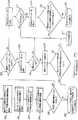
図2は、所望の視野内の垂直角度で入射する光線を示す本発明の一部を形成する光学システムの側断面図である。
図3は、図2と同様に、所望の視野を超えた垂直角度で入射する光線を示している。
図4は、図1に示された光学システムの平断面図であり、所望の視野内の水平角度での光線を有している。
図5は、本発明による自動的なヘッドライト減光システムのブロック図である。
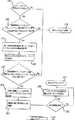
図6は、本発明による画像処理の全体フローチャートである。
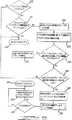
図7は、所望の視野内の車両のテールランプを検知するための方法を示すフローチャートである。
図8は、所望の視野内の他の車両からのヘッドランプを検知するフローチャートである。
本発明の詳細な説明
本発明による自動的なヘッドランプ減光システムは図2〜4に示されているような光学システム及び図5〜8に示されているような画像処理システムを含んでいる。妥当な最長時間、高ビームのヘッドランプを過度のグレアに別の車両の運転者が晒されることのない状態にとどまらせるため、本発明による自動的なヘッドランプ減光システムは、制御車両に関し他の車両の水平角度位置と同様に距離の関数として、車両の高ビームのヘッドランプを制御する。より詳細に後述するように、光学システムは他の車両のヘッドランプとテールランプとを識別するように適応されている。他の車両のヘッドランプ及びテールランプからの光線はピクセルセンサアレイで空間的に分離され、道路標識及び雪からの反射等のような他の周囲光源に関しヘッドランプとテールランプの高度の識別を提供する。光学システムは入射光源の水平及び垂直の両位置が光学システムの視野内に決定されるようにさせる。画像処理システムは制御車両に関し別の車両の距離及び水平角度位置の関数として、ヘッドランプの自動制御を供給するピクセルを処理する。そのようなものとして、本発明によるシステムは、他の車両の運転者が過度のグレア量に晒されるのを防いでいる間、可能な限り高ビームのヘッドランプをそのままの状態にさせることにより、車両の高ビームのヘッドランプの最適制御を供給するように適応されている。
光学システム
図2〜4を参照すると、光学システムは1対のレンズ103及び104、レンズケース105及び画像アレイセンサ106を含んでいる。図2及び3に最もよく示されているように、レンズ103及び104は、アレイの異なる部分に同じ視野の画像を可能にするため、別々に垂直に間隔をおいて配置されている。レンズ103,104間の距離は装置の視野内の光源に関し比較的小さいので、レンズ103及び104は通常、同じ視野を映す。
レンズ103は600nmより大きい波長の光を送るためと共にテールランプからの赤色光線101を画像アレイセンサ106の1方の半分に集束させるため、赤色のフィルター染料で形成されていてもよい。赤色のフィルター染料は可視スペクトルの青色端部でレンズ103にすべての光線を吸収させ、スペクトラムの赤色端部で光線を送る。そのようなものとして、ヘッドランプのように赤色でない光源から送られた光量は、テールランプからの光線がレンズ103を通って完全に送られている間、非常に減少される。そのようなものとして、テールランプから画像アレイセンサ106に映された光線の相対的輝度は非常に増加される。
レンズ104は600nm以下の波長の光を送るため、緑がかった青色の濾過された染料で形成されてもよい。レンズ104は画像アレイセンサ106の他の半分に光線を集束させるために使用される。緑がかった青色のフィルター染料は上述した赤色のフィルターに対して補色の効果を有している。特に、赤色のフィルター染料は、スペクトラムの赤色端部から光を吸収している間、可視スペクトラムの青色端部から光を送る。そのようなものとして、ヘッドライトのような源からの光のほとんどは、テールランプから発せられるすべての光が実質的に遮断されている間に、レンズ104を通って送られる。
ヘッドランプとテールランプの両方は赤外線光の実質量を発する。フィルター染料、または約750nmより大きい波長の光を阻止する分離したフィルターを有するレンズを利用することにより、ヘッドランプ及びテールランプにより送られた赤外線光はレンズ103及び104によって実質的に遮断されるだろう。赤外線光を除去することにより、赤色のフィルターを通って映された赤色光と緑がかったフィルターを通って映された赤色光との間の輝度の割合は実質的に増大されるだろう。
レンズ103及び104のための赤色及び緑がかった染料の使用は単に例示的である。レンズ103及び104のフィルターの特性は装置の感度を特定の光源に最適化するために選択される。例えば、新しい車両のヘッドランプまたはテールランプが異なるスペクトルの構成を有する別の光源、例えば、高輝度を放出するヘッドランプ及び異なるフィルター特性を要求するダイオードテールランプを発する光で置換されてもよい場合である。ヘッドランプ及びテールランプのスペクトル特性により、透明なレンズ103及び104は分離した色付きフィルターで使用されてもよい。
レンズ103及び104はアクリル性の球面レンズであってもよい。二者択一的に、レンズ103及び104は球面レンズに存在する色分散及び球面収差を最小にするため、非球面レンズとして形成されてもよい。球面及び非球面レンズの両方から形成された複合レンズもまた考えられている。
分離したレンズ103及び104の代わりに単一のレンズが使用されてもよい。単一レンズの使用はアレイの個々のピクセルに染料を含む完全または部分的な色付き画像アレイセンサに視野を映すために使用されてもよい。
図2及び3に最もよく示されているように、2つのレンズ103及び104と画像アレイセンサ106との間の水平距離は僅かに異なっている。2つのレンズ103及び104のオフセットは、材料の屈折率がそれを通って送られる光の波長で変化する事実の結果として作り出された色分散を補正する。2つのレンズ103及び104は可視スペクトルの異なる部分を送るので、レンズ103及び104と画像アレイセンサ106との間の距離はレンズ103及び104のそれぞれにより送られた光の周波帯のための分散を最小にするように最適化される。
上述したように、レンズ103を通って送られた光線101は、レンズ104を通って送られた光線102が画像アレイセンサ106の他の半分に映されている間、画像アレイセンサ106の1方の半分に映される。レンズ103及び104を通って送られる光線のそのような空間的分離を供給するため、レンズケース105はカットアウト107を供給され、好ましくは光吸収材料で形成または被覆されている。これらのカットアウト107は赤色レンズ103を通って送られる所望の最大垂直角度を超える光線が光線102のため予約された画像アレイセンサ106の部分に映されることを防止する。逆に、カットアウト107はまたレンズ104を通って送られた光線が光線101のため予約された画像アレイセンサ106の部分に映されることを防止する。
光学システムの視野は、画像アレイセンサ106に関してレンズ103及び104とカットアウト107の構成により形成されている。例えば、垂直方向に10度で水平方向に20度の例示的視野は下記に示した構成により創造されてもよい。特に、そのような視野のため、レンズ103及び104は小さな部分破断図で直径1.5mmを選択され、レンズの中心が1.0mm離れるようにレンズ103及び104を配置させる。レンズ103は画像アレイセンサ106から4.15mmに配置されているが、レンズ104は4.05mm離れて配置されている。レンズ103及び104の前後両面の半径は0.2mmの厚さで4.3mmである。
図3及び4に最もよく示されているように、円形のカットオフ108はレンズケース105に形成されている。通常矩形の一対の開口110は後壁112に形成されている。後の開口110は水平方向に1.6mmで垂直方向に0.8mmである。図4に最もよく示されているように、カットアウト107は後部開口110から前部カットアウト108の直径に次第に細くなっており、上述した視野を供給する。
したがって、上述した構成は所望の水平及び垂直視野の外部の光を妨げることができる。特に、図3は、システムが垂直視野を超えた角度で入射する光線を妨げる方法を示している。図4は、水平視野内で画像アレイセンサ106に映される光線を示している。
画像アレイセンサ106は、例えば、CMOS能動ピクセル画像センサアレイであってもよく、それは米国特許No.5,471,515に開示され、ここにインコーポレイテッドバイリファレンスされ、カリフォルニア州のPhotobit LLC of La Crasentaより利用可能である。CMOS能動ピクセル画像センサは同じチップの他の集積CMOS電子の性能と同様に比較的高感度で低電力消費を供給する。画像アレイセンサ106は50×5040mピクセルアレイであってもよい。画像アレイセンサ106のピクセル数は、レンズ103及び104が映す領域内にすべてのピクセルが入らないように選択される。追加のピクセルは予想された画像位置をオフセットすることにより機械的調整不良のための簡単な修正を可能にする。
画像アレイセンサ106は視野内の光源に関する空間的情報を供給する。アレイのサイズは限定されず、物理的及び経済的制限により選択され及び命令さえされてもよいが、アレイに存在するピクセル数は十分に空間の詳細を得るために選択される。画像アレイセンサ106は数百フィートのテールライトを正確に検知するために敏感でなければならない。そのような感度は、フレーム周期の間、アレイが光に晒される光場所の時間量を延ばすことにより達成されてもよい。フレーム周期は、画像処理システムに視野に入る他の車両を検知させるのに十分短い時間で、フレームを捕らえさせると共に画像処理システムに運ばせるように選択される。短い時間周期はまた集積化周期の間、フレーム内の動作量をも限定し、したがって、比較的より正確な瞬間画像を生成する。
ピクセルアレイの使用はまた他の利点を提供する。例えば、上述したように、フレームを捕らえる光集積化時間は変更可能である。そのような特徴は、暗闇で等級を変更する最適の結果をシステムに提供させる。画像アレイセンサの別の特徴はアレイ内のピクセルまたは個々のピクセルの副集合を利用する能力である。そのようなものとして、窓のサイズが減少されると、読み出し率が増加される。そのような特徴は、システムに街灯のような周囲の光源を識別させる。特に、そのような特徴は、システムにフレーム内の光源を配置させると共に60hzの数倍の大きさの割合で光源の幾つかのサンプルを捕らえさせる。特に、サンプルが120Hzの輝度変調を示している場合には、光源はおそらく街灯または60HzのAC電源から電力を供給された他の光源であろう。光源が変調されない場合には、光源はおそらく車両のDC電源により電力を供給されるだろう。
画像アレイセンサの別の潜在的な利点は、それが車両の前の視野をより高いピクセル解像度により直ぐに映させることである。したがって、システムは、制御車両に関して車両の角度が増加し、したがって、それらの領域の処理時間量を減少させると、有効なピクセル解像度が減少するように構成されてもよい。そのような構成は道路の横の反射する静止物体から光源に装置の感度を減少させる。
画像アレイセンサは、ピクセルが映す視野の領域の関数としてピクセルピッチが変化されることで製造されることができる。例えば、車両の中心の3度以内の水平角度に一致する空間を映すピクセルは10μmのピクセルピッチで供給されてもよい。3と6度の間の水平角度を映すピクセルは20μmピクセルピッチで供給されてもよいが、60度以上の角度を映すそれらは40μmピッチで供給されてもよい。そのような構成は検知領域を増加させないが、詳細に分解する能力は、比較的大きな距離のテールランプのその相対的サイズを考える重要な特徴を増加させる。例えば、200フィートの距離で4インチの直径のテールライトは0.11度以下の角度に延びている。50×50の画像アレイセンサが20度の視野を映すために使用される場合、テールランプはピクセルによって映された全領域のほぼ8%に延びている。
テールランプはその周囲の環境より比較的明るいが、テールライトにより与えられた赤色光はそのような距離で周囲光により淡くされる。所定領域の赤色光量を同じ領域の赤色でない光量と比較する時、そのような要素は重要である。比較された空間の領域が光源に関して大きい時、赤色光の割合は減少させられる。比較により、10μmのピクセルが40μmのピクセルの代わりにアレイ106の中心で使用される場合には、テールランプは全領域の0.04%延び、16倍改善されるであろう。
画像処理システム
画像処理が図5〜8に示されている。画像処理システムは画像アレイセンサ106、マイクロプロセッサ204、例えば、モトローラ型HC08、ヘッドランプ制御ユニット205及び1対のヘッドランプ206を含んでいる。上述したように、能動ピクセルアレイセンサは画像アレイセンサ106のため利用されてもよい。そのような能動ピクセルアレイセンサは画像アレイ201及びアナログデジタル変換器(ADC)202を含んでいる。タイミング及び制御回路はADC202と同様に画像アレイ201を制御するために使用され、集積化時間、読み出しタイミング、ピクセル選択、利得オフセット及び他の変数を制御する。マイクロプロセッサ204は画像アレイセンサ201により集められたデータを分析するために使用される。マイクロセンサ204はヘッドランプ制御ユニット、例えば、リレーとして遂行し、順番にヘッドランプ206を制御する伝統的なユニットと通信する。ヘッドランプ制御ユニット205は順番に、ヘッドランプ206に加えられた電圧を変え、高ビームまたは明るいランプを入り切りさせる。
ヘッドランプ制御のためのフローチャートが図6に示されている。システムは絶対的な光の測定、ADCパラメータまたは他の関数の調整のため時折中断のある連続サイクルで稼動する。
各サイクルの初めには、2つの画像がレンズ103及び104を通して取得される。ステップ302では、レンズ103及び104からの画像が分析され、テールランプを検知する。別の画像はレンズ104を通ってステップ303で取得される。レンズ104を通って取得された画像は、より低いレベルの反射及び不快な光源を拒絶している間に、低い充分な利得で取得され、接近するヘッドライトを検知する。画像が分析された後、システムは画像の非常に明るい光を検査し、ステップ305で制御車両の前で自動車が回転する時のように、視野内の車両のヘッドランプまたはテールランプの突然の出現を表示する。明るい光が検知される場合には、装置は直ぐにヘッドランプ206を減光し、後述するように時間検査を迂回する。その後、サイクルが繰り返される。明るい光がない場合には、システムはステップ307に進み、画像にヘッドランプまたはテールランプがあるかどうかを決定する。
フレームのヘッドランプまたはテールランプの存在または存在の欠乏を確認するため、非減光カウンター及び減光カウンターが使用される。これらのカウンターは、明るい光が検知された時、上述したこと以外で、ヘッドランプ206を減光または減光しないためヘッドランプ制御ユニット205に信号を送る前に、連続的なフレームからのテールランプからか又はヘッドランプからかにせよ特定の光源の検査を供給する。検査の供給により、装置内または画像の異常はヘッドランプ206の偽りの動作の要因とならないであろう。
作用することを要求された連続するフレームの数が届くまで、ヘッドランプまたはテールランプを有するフレームが検知される度に、減光カウンターは増やされる。クリアフレームが処理される度に、減光カウンターは0に設定される。非減光カウンターは各クリアフレームを増やし、ヘッドランプまたはテールランプを含む各フレームで0に設定する。減光または非減光することが要求される連続的なフレームの実際の数は装置の全体速度により決定される。フレームが検査のため使用される程、システムはノイズ及び異常に影響され難くなる。しかし、装置は有効となるように素早く反応できなければならず、検査フレームの数が比較的低く維持されるようになる。ステップ307で、ヘッドランプまたはテールランプが検知されるときは必ず、ステップ308で非減光カウンターは0に設定される。ステップ309で、システムはヘッドランプ206の高ビームがついているかどうかを検査する。高ビームが消えた場合、更なる動作は要求されず、サイクルはステップ317により示されているように繰り返される。高ビームがついている場合、減光カウンターはステップ310で増やされる。減光カウンターがステップ310で増やされた後、減光カウンターがヘッドランプ206を減光するように要求される連続フレームの数に達した場合には、システムはステップ311で検査する。もしそうであれば、システムはステップ306に進み、ヘッドランプ206を減光し、減光及び非減光カウンターの両方を再設定し、サイクルを繰り返す。そうでなければ、システムはサイクルを繰り返し、ステップ317に進む。
ステップ307で、画像にヘッドランプまたはテールランプがない場合には、減光カウンターはステップ312で0に設定される。その後、ステップ313で、システムは高ビーム206がついているかどうかを決定する。高ビームがついている場合には、システムはステップ317でサイクルを繰返し抜け出す。ステップ313で、ヘッドライトがついていない場合には、非減光カウンターが増やされる。非減光カウンターが増やされた後、ステップ315で、システムは、非減光カウンターが要求された連続するクリアフレームの数に届いて高ビーム206を作動させたかどうかを検査する。もしそうである場合には、高ビームはステップ316でつけられ、サイクルは繰り返される。非減光カウンターが明るいヘッドランプ206を作動するために要求される数より少ない場合には、システムはステップ317でサイクルを繰り返す。
テールライト処理のフローチャートが図7に示されている。より詳細に後述するように、テールライトのようなものを識別する主な方法は、レンズ103を通るピクセルのグレースケール値とレンズ104を通って映された同じ空間を表現するピクセルのグレースケール値とを比較することを含んでいる。レンズ103を通って映されるピクセルの値がレンズ104を通って映されるピクセルの値より著しく高い場合には、光源は赤色の光であると決定される。光が赤色であるかどうかを決定することに加えて、ピクセルのグレースケール値が閾値以上であるかどうかを決定することにより光がテールランプであると決定する前にシステムはまた赤色光の輝度をも検査する。当分野で公知なように、光源の輝度は観察者からの光源の距離の二乗で変化する。そのようなものとして、先導する車両の距離のおおよその決定がなされ、ヘッドランプを減光するおおよその時間を決定する。
閾値はいろいろな方法で計算されてもよい。例えば、現在の画像センサ及びADC設定の関数である所定の定数または数とすることができる。閾値は、周囲の光源を変化することにより生じる変動を除去するのに役立つ全体画像の平均のピクセル輝度の要素として、閾値を計算することにより決定される。更に、ピクセル値は、関心のピクセルの隣接領域のピクセルの平均と比較されてもよい。この局部平均方法は画像の比較的大きな適度な明るさの地点を車両の光源として見られることから防止する。より詳細には、遠くのテールランプは1つのピクセル以下に小さく延び、したがって、適度な輝度を有するだけとなるであろう。適度な明るさの画像の大きな地点はおそらく、大きな物体からの反射により発生されるであろう。多数のピクセルを延ばす近くのテールランプは飽和中心を有し、それは周囲のピクセルより明るく、それらを検知する同じ方法をも可能にする。
閾値はまた参照用テーブルまたは計算として閾値を空間的に変化させることにより決定されてもよい。しかし、DOT標準で許可される最も減光したテールライトにとって適切に減光が発生するように閾値が決定されなければならない。遠くの車両は制御車両の高ビームの最も強い部分に晒されやすく、したがって、図1に示されたような制御車両の直前でだけ光源することを要求する。したがって、制御車両の直前にない減光のためのより高い閾値と同時に比較的低い閾値は制御車両の直前に映された光源のため選択されてもよい。例えば、図1と関連させて説明したように、中心の右左3度の視野を映すピクセルのための閾値は車両の直前の赤色光のための閾値の約4倍の明るさで、6度の車両の12倍の明るさの画像アレイセンサ106に入射する光レベルに一致すべきである。そのように空間的に変化する閾値は、システムを制御車両の側面の領域に敏感でなくさせることにより、赤色の反射板により生じた偽りのテールランプの検知を除去するのに役立つ。
空間の画像領域のピクセル及び中心の上下の角度用の閾値を変化させるために同様のアプローチをとることができる。しかし、車両は道路の丘及びこぶのため垂直方向により頻繁に且つ迅速に動きがちであるので、垂直角度に関しテールライトの感度を決定する時、より連続的なアプローチをとることができる。そのため、比較的きつい垂直閾値を特定することにより、車両が数度上下に動く時、明るいヘッドランプ206を入り切りさせる。
ヒステリシス増倍器は、光源が閾値で又はその近くでグレースケールを有している時に、ヘッドランプ206の振動を防止する閾値に適用されてもよい。したがって、明るいヘッドランプ206が消えている場合には、たとえ最もかすかなテールランプが画像に存在していたとしても、閾値はすべてのピクセルのため低くなり、明るいヘッドランプが戻るのを防止する。しかし、明るいヘッドランプ206が付いている場合には、閾値はより高くなり、十分な明るさのテールランプだけが検知され、自動車が減光の範囲内にあり、ヘッドランプ206を減光させることを示している。
テールランプの検知に直面する最大の問題の1つは、通常、道路の縁及び郵便ポストの印として見出される角の反射物から反射された不快な赤色光である。上述した各種閾値方法は幾つかのこのノイズを除去するのに役立つ。しかし、車両が適当な角度で反射物に接近する時、赤色の反射物をテールランプと見分けることは比較的無理である。幸運にも、連続するフレームを検査すると共に時間が経つにつれてこれらの物体の動作を調査することにより、そのような反射は濾されることができる。時間が経つにつれてテールランプ及び画像の位置を記憶することにより、または、連続して数回、テールランプが配置される小さい関心領域を検知することにより、装置は右側の動作を探すと共に光源が反射物であるかどうかを決定することができる。更に、制御車両が静止物体を追い越す速度は、車両が別の進行車両を追い越す相対速度より非常に大きい。したがって、物体の輝度増加率は通常、別の車両のためより静止の反射物のための方が非常に大きいであろう。右側の水平動作と結びつく輝度のこの変化率は、偽りで検知されたテールランプの数を減少させるサインとして使用されることができる。
光源の空間動作を分析する計算的なより簡単な方法は、光源が配置される局部関心領域の連続的な幾つかの領域を単純にとることである。垂直及び水平方向の動作は先導する車両のテールランプにとって比較的遅い。連続的に数回ピクセルを簡単にサンプリングし、テールランプがすべてのサンプルに存在するかどうかを調べることは、画像内で迅速に動く物体を十分に除去することができる。
テールランプ処理のフローチャートは図7に示されている。当初、ステップ318では、システムはピクセルがテールランプ窓内にあるかどうかを確かめる。特に、上述したように、赤色光は画像アレイセンサ106の半分に映される。したがって、ピクセルが画像アレイセンサ106の適切な半分内にない場合には、システムはステップ319に進み、別のピクセルに移動する。上述したように、画像がテールランプかどうかを確かめるために2つの基準がある。第1の基準は、レンズ103を通るピクセル画像のグレースケール値とレンズ104を通って映された空間の同じ領域の対応するグレースケール値とを比較することに関する。レンズ103を通って映されたピクセルのグレースケール値がレンズ104を通って映された対応ピクセルのグレースケール値より著しく大きい場合には、テールランプを検知する基準の1つは満たされる。したがって、関心のピクセルがステップ318で確かめられたようなランプ窓内にある場合には、レンズ103を通って映されたピクセルのグレースケール値は、ステップ320で、レンズ104を通って映された対応ピクセルのグレースケール値と比較される。レンズ103を通るピクセル画像のグレースケール値がレンズ104により映される対応ピクセルよりn%大きくない場合には、システムはステップ319に進み、別のピクセルを検査する。さもなければ、システムはステップ321へ進み、それが映す空間領域に基づく特定のピクセルのための閾値を計算する。例えば、上述したように、ピクセル閾値は画像アレイセンサ内のそれらの空間的関係に基づいて変化されてもよい。
上述したように、テールランプのための他の基準は隣りのピクセルに関するピクセルの相対的輝度に関する。したがって、ステップ322で、システムは隣りのピクセルの平均グレースケール値を計算する。ステップ323で、レンズ103を通って映されたピクセルのためのピクセルグレースケール値がとなりのピクセルの平均グレースケール値よりn%大きいことが決定された場合には、システムはステップ324に進み、将来の参照フレームのためのテールランプリストにピクセルを加える。さもなければ、システムはステップ319に移動し、次のピクセルを移動する。ステップ325及び326では、上述されたように、検知された赤色光がテールランプかまたは反射物かをシステムが決定する。光が反射物であると決定された場合には、システムはステップ327に進み、次のピクセルに進む。さもなければ、ヘッドランプはステップ328で減光される。
ヘッドライト処理のためのフローチャートが図8に示されている。ヘッドランプ検知はテールランプ検知に類似している。主な相違はレンズ104が使用されることだけである。上述したように、ピクセル集積化時間はより短く、ADCパラメータは、ヘッドランプのように画像だけが非常に明るい物体を示しているようである。ほとんどの反射はADCのゼロ閾値より十分下になる低輝度の光源を有している。そのようなものとして、ピクセルは隣りのピクセルの局部平均の輝度と比較される。閾値の空間的な変化が設定され、視野の中心に対応するピクセルは左側の画像(左側の駆動領域)がより高い閾値を有することに対してもっと敏感なピクセルであるようになっている。しかし、それらの閾値は、ヘッドランプから観察される放出パターンの比較的広い変動のため、テールランプのための閾値と同じ程度に空間的に変化すべきではない。更に、接近する自動車の運転者への更なるグレアの比較的高い可能性のため、ヘッドランプは同方向に進む車両のテールランプが検知される場合より比較的迅速に制御されると共に減光されてもよい。テールランプ処理回路と同様に、ヒステリシスはヘッドランプのサイクリングを防ぐために付加されてもよい。
ヘッドランプ検知の更なる懸念は、接近する車両が突然、制御車両の視野に入る時、例えば、角を曲がるまたは同様の状況の時、特に重要になる接近する車両間の距離の急速な減少から生じる。この理由にとって、光源が一定の絶対的な高レベルの輝度の閾値以上の場合には、更なるフラッグは車両に明るいヘッドランプを直ぐに減光させると共に検査を迂回させるために使用される。
ヘッドランプ検知を悪化させる主な不快な光源は、街灯及び電気的に照らされた道路標識のような、頭上のライトから来る。そのような不快な光源を除去する1つの方法は、それらの動作を分析することである。特に、すべての頭上の街灯は制御車両が動いている時に画像の上方へ垂直に動くであろう。この動作を分析することは幾つかの街灯を検知する有効な方法を供給する。不幸にも、遠くの街灯は遠くのヘッドライトとほとんど同じ高低角であることが明らかであり、画像の垂直上昇割合は街灯がもっと近づくまで大きくならない。しかし、上述するように、街灯はAC制御され、したがって、120Hzの輝度変調に晒される。DC源により電力を供給されたヘッドランプはこの特性を示さない。したがって、画像アレイセンサ106は窓で素早く連続する幾つかの読みを取るため小数のピクセルを使用することができる。窓が十分小さい場合には、窓は秒当たり数百のフレームを読むことができる。一度、光源が画像で確認されると、幾つかのフレームが240Hz又はそれ以上の割合で読み出される。これらの読みはその後分析され、輝度変調を検知する。変調が存在する場合には、光源はAC源から生じ無視できる。二者択一的に、ホトダイオードが低域フィルターと関連して使用することができ、非変調光にAC変調された画像の光の割合を決定する。光源のかなりの部分がAC変調される場合には、画像に存在する光源はAC光からであると仮定される。そうでなければ、光源はDC源からであると仮定される。
ヘッドランプ処理のためのフローチャートが図8に示されている。当初、ステップ329で、システムはピクセルがヘッドランプ(すなわち、画像アレイセンサ106がレンズ104を通って映された光線のため保存したその部分)にあるかどうかを決定する。もしなければ、システムはステップ330に進み、次のピクセルを検査する。さもなければ、システムはステップ331でピクセルを検査し、ピクセルが上述したように120Hzで変調されるかどうかを決定する。もしそうであれば、光源は街灯であると仮定され、したがって、システムはステップ330で次のピクセルに進む。ピクセルが120Hzの輝度変調に晒されない場合には、その後、システムはステップ332で、隣りのピクセルの平均グレースケールを計算する。ステップ333で、システムはそれが映す空間の領域に基づいて特定のピクセルのための閾値を決定する。次に、システムはステップ334で、ピクセルのグレースケール値を絶対的な高レベルの閾値と比較し、例えば、接近する自動車が制御車両の視野に来るかどうかを決定する。もしそうであれば、システムはステップ335に進み、フラッグを設定し、即座の減光を行なわせる。さもなければ、システムはステップ336に進み、ピクセルのグレースケール値が隣りのピクセルの平均よりn%大きいかどうかを決定する。そうでなければ、システムはステップ330に戻り、次のピクセルを検査する。そうでなければ、システムはステップ337に進み、将来の参照フレームのためヘッドランプリストにピクセルを付加する。
上述したように、システムはステップ338及び339で上述した光源を検査し、光源が街灯かどうかを決定する。光源が街灯でないとシステムが決定した場合には。システムはステップ340に進み、フラッグを設定し、ヘッドランプ206の減光を行わせる。光源が街灯であるとシステムが決定すると、システムはステップ341に進み、次のピクセルに進む。伝統的な車両ランプシステムは明るいランプの選択をオンかオフのいずれかにさせる。本発明はヘッドランプシステムの使用に容易に適用可能であり、ヘッドライトは視野の他の車両の距離に基づいて変化する輝度までつけられることができる。そのような実施例では、ヘッドランプの輝度は、全体の輝度レベルを減少又は増加させるためヘッドランプの衝撃係数を変調することを含む各種技術によって変更されてもよい。
各種輝度のヘッドランプは又よりよいノイズ濾過ともなる。特に、光源が検知され、車両の制御されたヘッドランプの輝度を減少させる時は必ず、他の画像が検知され、これらの他の光源の輝度は同様の量減少するかどうかを決定する。そうであれば、システムは光源が車両のヘッドランプからの反射であると決定することができるだろう。そのような情報は比較的有効な手段を供給するフィードバックとして使用されることができ、制御車両のヘッドランプの反射により発生する不快な光を除去する。そのような実施例では、上述した輝度の閾値は使用されないであろう。より詳細には、画像の最も明るいヘッドランプ及びテールランプの輝度は制御車両のヘッドランプの輝度を決定するために使用される。画像のヘッドランプまたはテールランプが明るくなるにつれて、制御されたヘッドランプはますます減光される。
明らかに、上記教示を考慮して、本発明の多くの修正及び変更が可能である。したがって、本発明は、添付した請求の範囲内で、特に上述されたものとは別な手段で実施されてもよいことが理解されるであろう。Field of the invention
The present invention relates to a system for automatically dimming high beam headlights of a vehicle, and more particularly to a system including an improved optical system and an image processing system, and to an improvement in vehicle headlamps and vehicle taillights with respect to other ambient light sources. An optical system adapted to identify both horizontal and vertical positions of light rays within a given field of view and to spatially separate the light rays of a pixel sensor array to provide such identification. The image processing system provides further identification of the surrounding light source to automatically dimme the high beam of the vehicle headlamp as a function of the angular position of another vehicle with respect to the controlling vehicle.
Description of the prior art
Regulations set out by the US Department of Transportation (DOT) govern the emission of light from high-beam headlamps in vehicles. Various state regulations are used to control the amount of glare experienced by drivers of other vehicles, whether the vehicle is traveling in the same direction as the control vehicle or in the opposite direction.
According to the DOT regulations, the emission of high beam headlamps in known vehicles provides a luminance of 40,000 cd at 0 degrees, 10,000 cd at 3 degrees, 3,250 cd at 6 degrees, 1,500 cd at 9 degrees and 750 cd at 12 degrees. An example of such an emission pattern is shown in FIG. To prevent the illumination of a 0.5 foot candle (fc) from illuminating another vehicle, the vehicle's high beam headlamp must be located within 230 feet of the other vehicle at 0 degrees and at a horizontal position of 3 degrees relative to the reference plane. It should be dimmed within 115 feet, and 65 feet of other vehicle locations is 6 degrees with respect to the control vehicle.
Various known headlight dimmer control systems are known in the art. To prevent other vehicle drivers from being exposed to excessive glare levels, such automatic headlamp dimmer systems must detect both headlights as well as other vehicle taillights. Must. While many known systems are capable of detecting headlamps of an approaching vehicle satisfactorily, such systems are known to be inadequate for detecting taillights of vehicles traveling ahead of a controlled vehicle. As such, such a system would eventually automatically diminish the high beam headlamps and prevent the driver of the vehicle traveling in the same direction as the control vehicle from being exposed to excessive glare levels. Can not.
U.S. Pat. No. 5,537,003, assigned to the same assignee of the present invention, discloses an automatic headlamp dimmer system that includes an optical system for detecting tail lamps as well as head lamps. The '003 patent discloses a single photodiode having a mechanical scanning device for scanning a given field of view. While the system provides relatively good detection of headlamps as well as taillights, the optical subsystem is rather complicated and expensive to manufacture.
Summary of the present invention
It is an object of the present invention to solve various problems of the prior art.
It is another object of the present invention to provide a dimming system for vehicle headlamps that eliminates the need for a mechanical optical scanning system.
It is another object of the present invention to provide a headlamp dimming system adapted to dimming high beam headlights at different distances as a function of the horizontal angular position of another vehicle with respect to the controlling vehicle.
In summary, the present invention relates to a system for automatically dimming vehicle headlamps. The system includes an optical system and an image processing system. The optical system is configured to identify the headlamp and the taillamp and to focus light rays from the headlamp and the taillamp on different portions of the pixel sensor array. As with the image processing system, the optical system provides a relatively high degree of discrimination between the headlamps and tail lamps of the other vehicle, and the high beam head of the control vehicle as a function of distance as well as the horizontal angle position of the other vehicle with respect to the control vehicle. The lamp can also be controlled.
[Brief description of the drawings]
These and other objects of the present invention will be readily understood in connection with the following specification and the accompanying drawings.
FIG. 1 is a plan view showing a headlamp emission pattern of a conventional high beam headlamp.
FIG. 2 is a side cross-sectional view of an optical system forming part of the present invention, showing rays incident at a normal angle within the desired field of view.
FIG. 3, like FIG. 2, shows rays incident at a vertical angle beyond the desired field of view.
FIG. 4 is a plan cross-sectional view of the optical system shown in FIG. 1, having rays at a horizontal angle within the desired field of view.
FIG. 5 is a block diagram of an automatic headlight dimming system according to the present invention.
FIG. 6 is an overall flowchart of the image processing according to the present invention.
FIG. 7 is a flowchart illustrating a method for detecting a tail lamp of a vehicle within a desired field of view.
FIG. 8 is a flowchart for detecting a headlamp from another vehicle within a desired field of view.
Detailed description of the invention
An automatic headlamp dimming system according to the present invention includes an optical system as shown in FIGS. 2-4 and an image processing system as shown in FIGS. The automatic headlamp dimming system according to the present invention is useful for controlling vehicles in order to keep the high beam headlamps in the vehicle for a reasonable maximum time without exposing the driver of another vehicle to excessive glare. Control the high beam headlamps of the vehicle as a function of distance as well as the horizontal angular position of the vehicle. As will be described in more detail below, the optical system is adapted to distinguish headlamps and taillamps of other vehicles. Light rays from other vehicle headlamps and taillights are spatially separated by a pixel sensor array to provide headlight and taillight altitude discrimination with respect to other ambient light sources such as road signs and reflections from snow. The optical system allows both the horizontal and vertical position of the incident light source to be determined within the field of view of the optical system. The image processing system processes pixels that provide automatic control of the headlamps as a function of the distance and horizontal angular position of another vehicle with respect to the controlling vehicle. As such, the system according to the present invention leaves the high beam headlamps as high as possible while preventing other vehicle drivers from being exposed to excessive amounts of glare. It is adapted to provide optimal control of the high beam headlamp of the vehicle.
Optical system
Referring to FIGS. 2-4, the optical system includes a pair of
Both headlamps and taillamps emit a substantial amount of infrared light. By utilizing a filter dye or a lens with a separate filter that blocks light of wavelengths greater than about 750 nm, the infrared light transmitted by the headlamps and taillights will be substantially blocked by
The use of red and greenish dyes for
The
A single lens may be used instead of
As best shown in FIGS. 2 and 3, the horizontal distance between the two
As described above, the
The field of view of the optical system is formed by the configuration of
As best shown in FIGS. 3 and 4, a
Thus, the above-described arrangement can block light outside the desired horizontal and vertical fields. In particular, FIG. 3 illustrates how the system blocks light rays incident at angles beyond the vertical field of view. FIG. 4 shows the light rays projected on the
The
The use of a pixel array also offers other advantages. For example, as described above, the optical integration time for capturing a frame can be changed. Such features allow the system to provide optimal results of changing grades in the dark. Another feature of image array sensors is the ability to utilize a subset of the pixels or individual pixels in the array. As such, as the size of the window is reduced, the readout rate is increased. Such features allow the system to identify ambient light sources, such as street lamps. In particular, such features allow the system to place the light source in the frame and capture several samples of the light source at a rate several times as large as 60 hz. In particular, if the sample shows 120 Hz intensity modulation, the light source will likely be a street light or other light source powered from a 60 Hz AC power source. If the light source is not modulated, the light source will likely be powered by the vehicle's DC power supply.
Another potential advantage of an image array sensor is that it more quickly mirrors the front field of view of the vehicle with higher pixel resolution. Thus, the system may be configured such that as the angle of the vehicle with respect to the control vehicle increases, and thus the amount of processing time in those regions decreases, the effective pixel resolution decreases. Such an arrangement reduces the sensitivity of the device from a stationary stationary object beside the road to the light source.
Image array sensors can be manufactured by varying the pixel pitch as a function of the area of the field of view that the pixels project. For example, pixels representing a space corresponding to a horizontal angle within 3 degrees of the center of the vehicle may be provided at a pixel pitch of 10 μm. Pixels displaying a horizontal angle between 3 and 6 degrees may be provided at a 20 μm pixel pitch, but those displaying angles greater than 60 degrees may be provided at a 40 μm pitch. Although such an arrangement does not increase the sensing area, the ability to resolve in detail increases an important feature that accounts for its relative size of the tail lamp at relatively large distances. For example, at a distance of 200 feet, a 4 inch diameter taillight extends to an angle of less than 0.11 degrees. If a 50x50 image array sensor is used to project a 20 degree field of view, the tail lamp extends to approximately 8% of the total area imaged by the pixel.
Although the tail lamp is relatively brighter than its surroundings, the red light provided by the tail light is dimmed by ambient light at such a distance. Such factors are important when comparing the amount of red light in a given area to the amount of non-red light in the same area. When the area of the compared space is large with respect to the light source, the proportion of red light is reduced. By comparison, if 10 μm pixels are used at the center of the
Image processing system
Image processing is shown in FIGS. The image processing system includes an
FIG. 6 shows a flowchart for headlamp control. The system operates in continuous cycles with occasional interruptions for absolute light measurement, adjustment of ADC parameters or other functions.
At the beginning of each cycle, two images are acquired through
Non-dimming counters and dim counters are used to determine the presence or lack of presence of headlamps or taillamps in the frame. These counters, when a bright light is detected, except from the tail lamps from successive frames before sending a signal to the
The dimming counter is incremented each time a frame with a headlamp or taillamp is detected, until the number of consecutive frames required to work has been reached. Each time a clear frame is processed, the dimming counter is set to zero. The non-dimming counter increments each clear frame and sets it to 0 in each frame including a headlamp or taillamp. The actual number of consecutive frames required to be dimmed or non-dimmed is determined by the overall speed of the device. The more a frame is used for inspection, the less susceptible the system is to noise and anomalies. However, the device must be able to react quickly to be effective and the number of test frames will be kept relatively low. Whenever a head lamp or a tail lamp is detected in step 307, the non-dimming counter is set to 0 in
If there is no headlamp or taillamp in the image at step 307, the dimming counter is set to 0 at
FIG. 7 shows a flowchart of the taillight process. As will be described in more detail below, the primary method of identifying such things as taillights is the grayscale value of the pixel passing through
The threshold may be calculated in various ways. For example, it can be a predetermined constant or number that is a function of the current image sensor and ADC settings. The threshold value is determined by calculating the threshold value as a factor of the average pixel brightness of the whole image, which helps to eliminate fluctuations caused by changing the surrounding light source. Further, the pixel value may be compared to an average of pixels in a region adjacent to the pixel of interest. This local averaging method prevents relatively large, moderately bright spots in the image from being seen as a vehicle light source. More specifically, a distant tail lamp will extend less than one pixel and will therefore only have a reasonable brightness. Large points in a reasonably bright image will likely be generated by reflections from large objects. A nearby tail lamp that extends a large number of pixels has a saturation center, which is brighter than the surrounding pixels and also allows the same way of detecting them.
The threshold may also be determined by spatially varying the threshold as a look-up table or calculation. However, the threshold must be determined so that dimming occurs appropriately for the most dimmed taillights allowed by the DOT standard. Distant vehicles are subject to the strongest part of the high beam of the control vehicle, and therefore require only a light source in front of the control vehicle as shown in FIG. Thus, a relatively low threshold may be selected for the light source imaged immediately before the control vehicle, as well as a higher threshold for dimming that is not immediately before the control vehicle. For example, as described in connection with FIG. 1, the threshold value for a pixel that reflects a 3 degree field of view to the right and left of the center is about four times as bright as the threshold value for red light just before the vehicle, and is 6 degrees. It should match the light level incident on the
A similar approach can be taken to vary the thresholds for the pixels in the image region of space and the angles above and below the center. However, a more continuous approach can be taken when determining taillight sensitivity with respect to vertical angle, as vehicles tend to move more frequently and quickly in the vertical direction due to road hills and bumps. Therefore, by specifying a relatively tight vertical threshold, the
A hysteresis multiplier may be applied to the threshold to prevent vibration of
One of the biggest problems facing the detection of tail lamps is the unpleasant red light reflected from corner reflectors, which are usually found on the edges of roads and as marks on post boxes. The various thresholding methods described above help to remove some of this noise. However, when the vehicle approaches the reflector at an appropriate angle, it is relatively impossible to distinguish the red reflector from the tail lamp. Fortunately, such reflections can be filtered out by inspecting successive frames and investigating the behavior of these objects over time. By storing the position of the tail lamp and the image over time, or by detecting several small regions of interest where the tail lamp is located several times in a row, the device looks for the right-hand movement and the light source is reflected. You can decide if there is. Further, the speed at which the controlled vehicle overtakes a stationary object is much greater than the relative speed at which the vehicle overtakes another traveling vehicle. Thus, the rate of increase in brightness of the object will typically be much greater for stationary reflectors than for another vehicle. This rate of change in luminance associated with horizontal movement on the right side can be used as a sign to reduce the number of falsely detected tail lamps.
A computationally simpler way of analyzing the spatial behavior of the light source is to simply take several successive regions of the local region of interest where the light source is located. Vertical and horizontal movements are relatively slow for the tail lamps of leading vehicles. Simple sampling of pixels several times in a row and checking if a tail lamp is present in every sample can sufficiently remove fast moving objects in the image.
A flowchart of the tail lamp process is shown in FIG. Initially, in
As mentioned above, another criterion for a tail lamp relates to the relative brightness of a pixel with respect to neighboring pixels. Thus, in
A flowchart for the headlight process is shown in FIG. Headlamp detection is similar to taillamp detection. The only difference is that a
A further concern for headlamp detection is that when approaching vehicles suddenly enter the field of view of the control vehicle, for example, when turning corners or similar situations, the rapid decrease in distance between approaching vehicles becomes especially important. Occurs. For this reason, if the light source is above a certain absolute high-level brightness threshold, a further flag is used to cause the vehicle to immediately dimm the bright headlamps and bypass the inspection.
The main unpleasant light sources that exacerbate headlamp detection come from overhead lights, such as street lamps and electrically illuminated road signs. One way to eliminate such annoying light sources is to analyze their operation. In particular, all overhead street lights will move vertically above the image when the control vehicle is moving. Analyzing this behavior provides an effective way to detect some street lights. Unfortunately, it is clear that distant streetlights have almost the same elevation as distant headlights, and the vertical rise rate of the image does not increase until the streetlights get closer. However, as mentioned above, the streetlights are AC controlled and are therefore exposed to 120 Hz intensity modulation. Headlamps powered by a DC source do not exhibit this property. Thus, the
A flowchart for the headlamp processing is shown in FIG. Initially, at
As described above, the system examines the light source described above in
Various brightness headlamps also provide better noise filtering. In particular, whenever a light source is detected and reduces the brightness of the vehicle's controlled headlamps, another image is detected and determines whether the brightness of these other light sources is reduced by a similar amount. If so, the system could determine that the light source is a reflection from the vehicle headlamp. Such information can be used as feedback to provide relatively effective means, eliminating the offending light generated by the reflections of the headlamps of the control vehicle. In such an embodiment, the luminance threshold described above would not be used. More specifically, the brightness of the brightest headlamps and taillights of the image is used to determine the brightness of the headlamps of the control vehicle. As the headlights or taillights of the image become brighter, the controlled headlights are increasingly dimmed.
Obviously, many modifications and variations of the present invention are possible in light of the above teachings. Therefore, it will be appreciated that the invention may be practiced otherwise than as specifically described above, within the scope of the appended claims.
Claims (33)
Translated fromJapanese所定の視野内の2つの所定のスペクトル帯域を選択的に透過するように構成された所定の視野内の外部の光源を映す光学システムと、
前記光学システムからの画像を処理すると共に光の同じスペクトル帯域を映すピクセルの相対出力の関数としてヘッドランプの状態を制御する制御信号を供給するための画像処理システムと、を含み、
ヘッドランプの高ビームの輝度が可変であり、光源が検知され、ヘッドランプの輝度を減少させるとき、前記画像処理システムは、他の画像を検知し、他の画像の光源の強度が同様の量減少するかどうか決定し、同様の量減少すれば、前記画像処理システムは、光源が制御車両のヘッドランプからの反射であると決定することを特徴とする制御システム。A control system for automatically controlling a state of a headlamp of a control vehicle,
An optical system for projecting an external light source within the predetermined field of view configured to selectively transmit two predetermined spectral bands within the predetermined field of view;
An image processing system for processing an image from the optical system and providing a control signal for controlling a state of a headlamp as a function of a relative output of a pixel that projects the same spectral band of light,
When the brightness of the high beam of the headlamp is variable, the light source is detected, and the brightness of the headlamp is reduced, the image processing system detects another image and the intensity of the light source of the other image is a similar amount. A control system for determining whether to decrease, and if so, the image processing system determines that the light source is a reflection from a headlamp of a control vehicle.
少なくとも1つのヘッドランプの輝度が可変であり、
所定の視野内の外部の光源を映す光学システムと、
前記光学システムからの画像を処理すると共に少なくとも1つのヘッドランプの輝度を制御する制御信号を供給する画像処理システムであって、光源が検知され、ヘッドランプの輝度を減少させるとき、他の画像を検知し、他の画像の光源の強度が同様の量減少するかどうか決定し、同様の量減少すれば、前記画像処理システムは、光源が制御車両のヘッドランプからの反射であると決定する画像処理システムと、
を含むことを特徴とするシステム。A control system for automatically controlling a state of a headlamp of a control vehicle,
Brightness of at least one headlamp is variable;
An optical system that projects an external light source within a predetermined field of view;
An image processing system for processing an image from the optical system and providing a control signal for controlling the brightness of at least one headlamp, wherein when a light source is detected and the brightness of the headlamp is reduced, another image is generated. Detecting and determining whether the intensity of the light source in the other image decreases by a similar amount, and if so, the image processing system determines that the light source is a reflection from the headlights of the control vehicle. A processing system;
A system comprising:
所定の視野内の外部の光源を映す光学システムと、
前記光学システムからの画像を処理すると共に前記ヘッドランプの輝度を制御するため制御信号を供給し、不快な光源のAC輝度変調を検知することにより前記不快な光源を検知する手段を含み、輝度変調が前記不快な光源が電力を供給される交流源から生じる画像処理システムと、
を含むことを特徴とするシステム。A control system for automatically controlling a state of a headlamp of a control vehicle,
An optical system that projects an external light source within a predetermined field of view;
Means for processing an image from the optical system and for providing a control signal to control the brightness of the headlamp, and detecting the unpleasant light source by detecting the AC brightness modulation of the unpleasant light source, comprising: An image processing system wherein the unpleasant light source results from an alternating current source being powered,
A system comprising:
Applications Claiming Priority (3)
| Application Number | Priority Date | Filing Date | Title |
|---|---|---|---|
| US08/831,232 | 1997-04-02 | ||
| US08831232US5837994C1 (en) | 1997-04-02 | 1997-04-02 | Control system to automatically dim vehicle head lamps |
| PCT/US1998/005962WO1998043850A1 (en) | 1997-04-02 | 1998-03-26 | Control system to automatically dim vehicle head lamps |
Related Child Applications (1)
| Application Number | Title | Priority Date | Filing Date |
|---|---|---|---|
| JP2004072772ADivisionJP4108631B2 (en) | 1997-04-02 | 2004-03-15 | Control system that automatically dims vehicle headlights |
Publications (2)
| Publication Number | Publication Date |
|---|---|
| JP2001519744A JP2001519744A (en) | 2001-10-23 |
| JP3568210B2true JP3568210B2 (en) | 2004-09-22 |
Family
ID=25258611
Family Applications (2)
| Application Number | Title | Priority Date | Filing Date |
|---|---|---|---|
| JP54179798AExpired - LifetimeJP3568210B2 (en) | 1997-04-02 | 1998-03-26 | Control system for automatically dimming vehicle headlights |
| JP2004072772AExpired - LifetimeJP4108631B2 (en) | 1997-04-02 | 2004-03-15 | Control system that automatically dims vehicle headlights |
Family Applications After (1)
| Application Number | Title | Priority Date | Filing Date |
|---|---|---|---|
| JP2004072772AExpired - LifetimeJP4108631B2 (en) | 1997-04-02 | 2004-03-15 | Control system that automatically dims vehicle headlights |
Country Status (10)
| Country | Link |
|---|---|
| US (6) | US5837994C1 (en) |
| EP (2) | EP1129902B1 (en) |
| JP (2) | JP3568210B2 (en) |
| KR (1) | KR100493581B1 (en) |
| AT (2) | ATE256576T1 (en) |
| AU (1) | AU6777098A (en) |
| CA (1) | CA2284496C (en) |
| DE (2) | DE69802511T2 (en) |
| ES (2) | ES2213076T3 (en) |
| WO (1) | WO1998043850A1 (en) |
Cited By (4)
| Publication number | Priority date | Publication date | Assignee | Title |
|---|---|---|---|---|
| JP2007076429A (en)* | 2005-09-13 | 2007-03-29 | Koito Mfg Co Ltd | Head lamp system |
| JP2007076428A (en)* | 2005-09-13 | 2007-03-29 | Koito Mfg Co Ltd | Head lamp system |
| JP2011110999A (en)* | 2009-11-25 | 2011-06-09 | Koito Mfg Co Ltd | Vehicular headlight system |
| JP2012240523A (en)* | 2011-05-18 | 2012-12-10 | Denso Corp | Light distribution control device |
Families Citing this family (332)
| Publication number | Priority date | Publication date | Assignee | Title |
|---|---|---|---|---|
| US7339149B1 (en) | 1993-02-26 | 2008-03-04 | Donnelly Corporation | Vehicle headlight control using imaging sensor |
| US5877897A (en) | 1993-02-26 | 1999-03-02 | Donnelly Corporation | Automatic rearview mirror, vehicle lighting control and vehicle interior monitoring system using a photosensor array |
| US5910854A (en) | 1993-02-26 | 1999-06-08 | Donnelly Corporation | Electrochromic polymeric solid films, manufacturing electrochromic devices using such solid films, and processes for making such solid films and devices |
| US6822563B2 (en) | 1997-09-22 | 2004-11-23 | Donnelly Corporation | Vehicle imaging system with accessory control |
| US5670935A (en) | 1993-02-26 | 1997-09-23 | Donnelly Corporation | Rearview vision system for vehicle including panoramic view |
| US6396397B1 (en) | 1993-02-26 | 2002-05-28 | Donnelly Corporation | Vehicle imaging system with stereo imaging |
| US5796094A (en) | 1993-02-26 | 1998-08-18 | Donnelly Corporation | Vehicle headlight control using imaging sensor |
| US5668663A (en) | 1994-05-05 | 1997-09-16 | Donnelly Corporation | Electrochromic mirrors and devices |
| US6891563B2 (en) | 1996-05-22 | 2005-05-10 | Donnelly Corporation | Vehicular vision system |
| US8538636B2 (en)* | 1995-06-07 | 2013-09-17 | American Vehicular Sciences, LLC | System and method for controlling vehicle headlights |
| US20070154063A1 (en)* | 1995-06-07 | 2007-07-05 | Automotive Technologies International, Inc. | Image Processing Using Rear View Mirror-Mounted Imaging Device |
| US7655894B2 (en) | 1996-03-25 | 2010-02-02 | Donnelly Corporation | Vehicular image sensing system |
| US6049171A (en) | 1998-09-18 | 2000-04-11 | Gentex Corporation | Continuously variable headlamp control |
| US6587573B1 (en) | 2000-03-20 | 2003-07-01 | Gentex Corporation | System for controlling exterior vehicle lights |
| US6130421A (en)* | 1998-06-09 | 2000-10-10 | Gentex Corporation | Imaging system for vehicle headlamp control |
| US6631316B2 (en) | 2001-03-05 | 2003-10-07 | Gentex Corporation | Image processing system to control vehicle headlamps or other vehicle equipment |
| US5837994C1 (en)* | 1997-04-02 | 2001-10-16 | Gentex Corp | Control system to automatically dim vehicle head lamps |
| US5990469A (en)* | 1997-04-02 | 1999-11-23 | Gentex Corporation | Control circuit for image array sensors |
| US6861809B2 (en)* | 1998-09-18 | 2005-03-01 | Gentex Corporation | Headlamp control to prevent glare |
| US8120652B2 (en)* | 1997-04-02 | 2012-02-21 | Gentex Corporation | System for controlling vehicle equipment |
| US6774988B2 (en)* | 2002-07-30 | 2004-08-10 | Gentex Corporation | Light source detection and categorization system for automatic vehicle exterior light control and method of manufacturing |
| US6611610B1 (en)* | 1997-04-02 | 2003-08-26 | Gentex Corporation | Vehicle lamp control |
| US7653215B2 (en) | 1997-04-02 | 2010-01-26 | Gentex Corporation | System for controlling exterior vehicle lights |
| US6172613B1 (en) | 1998-02-18 | 2001-01-09 | Donnelly Corporation | Rearview mirror assembly incorporating vehicle information display |
| US8294975B2 (en) | 1997-08-25 | 2012-10-23 | Donnelly Corporation | Automotive rearview mirror assembly |
| US6326613B1 (en) | 1998-01-07 | 2001-12-04 | Donnelly Corporation | Vehicle interior mirror assembly adapted for containing a rain sensor |
| US6124886A (en) | 1997-08-25 | 2000-09-26 | Donnelly Corporation | Modular rearview mirror assembly |
| US6313454B1 (en) | 1999-07-02 | 2001-11-06 | Donnelly Corporation | Rain sensor |
| US6353392B1 (en) | 1997-10-30 | 2002-03-05 | Donnelly Corporation | Rain sensor with fog discrimination |
| DE19742093A1 (en)* | 1997-09-24 | 1999-03-25 | Kostal Leopold Gmbh & Co Kg | Photoelectric sensor array |
| US6278377B1 (en) | 1999-08-25 | 2001-08-21 | Donnelly Corporation | Indicator for vehicle accessory |
| US6445287B1 (en) | 2000-02-28 | 2002-09-03 | Donnelly Corporation | Tire inflation assistance monitoring system |
| US8288711B2 (en) | 1998-01-07 | 2012-10-16 | Donnelly Corporation | Interior rearview mirror system with forwardly-viewing camera and a control |
| US6693517B2 (en) | 2000-04-21 | 2004-02-17 | Donnelly Corporation | Vehicle mirror assembly communicating wirelessly with vehicle accessories and occupants |
| US6477464B2 (en) | 2000-03-09 | 2002-11-05 | Donnelly Corporation | Complete mirror-based global-positioning system (GPS) navigation solution |
| US6329925B1 (en) | 1999-11-24 | 2001-12-11 | Donnelly Corporation | Rearview mirror assembly with added feature modular display |
| US6420975B1 (en) | 1999-08-25 | 2002-07-16 | Donnelly Corporation | Interior rearview mirror sound processing system |
| US6411444B1 (en)* | 1998-06-30 | 2002-06-25 | Corning Precision Lens, Incorporated | Lenses for electronic imaging systems having long wavelength filtering properties |
| WO2000022881A2 (en) | 1998-10-12 | 2000-04-20 | Control Devices, Inc. | Ambient light sensor |
| WO2000043236A1 (en)* | 1999-01-25 | 2000-07-27 | Gentex Corporation | Vehicle equipment control with semiconductor light sensors |
| US6166698A (en) | 1999-02-16 | 2000-12-26 | Gentex Corporation | Rearview mirror with integrated microwave receiver |
| JP4285716B2 (en)* | 1999-03-26 | 2009-06-24 | 株式会社小糸製作所 | Vehicle headlamp device |
| DE10017139B4 (en)* | 1999-04-07 | 2007-01-04 | Honda Giken Kogyo K.K. | Illumination control device for an automatic follow-up driving system |
| US6340864B1 (en)* | 1999-08-10 | 2002-01-22 | Philips Electronics North America Corporation | Lighting control system including a wireless remote sensor |
| EP1103420B1 (en) | 1999-11-24 | 2006-06-21 | Donnelly Corporation | Rearview mirror assembly with utility functions |
| DE20003339U1 (en)* | 2000-02-24 | 2001-06-28 | Bombik, Franz, 22850 Norderstedt | Lighting unit for muscle-powered vehicles |
| AU2001243285A1 (en) | 2000-03-02 | 2001-09-12 | Donnelly Corporation | Video mirror systems incorporating an accessory module |
| US7480149B2 (en) | 2004-08-18 | 2009-01-20 | Donnelly Corporation | Accessory module for vehicle |
| US7167796B2 (en) | 2000-03-09 | 2007-01-23 | Donnelly Corporation | Vehicle navigation system for use with a telematics system |
| US7370983B2 (en) | 2000-03-02 | 2008-05-13 | Donnelly Corporation | Interior mirror assembly with display |
| US6403942B1 (en)* | 2000-03-20 | 2002-06-11 | Gentex Corporation | Automatic headlamp control system utilizing radar and an optical sensor |
| AU2005200407B2 (en)* | 2000-03-20 | 2006-09-28 | Gentex Corporation | System for controlling exterior vehicle lights |
| US6396408B2 (en) | 2000-03-31 | 2002-05-28 | Donnelly Corporation | Digital electrochromic circuit with a vehicle network |
| DE10052541A1 (en)* | 2000-10-23 | 2002-04-25 | Patent Treuhand Ges Fuer Elektrische Gluehlampen Mbh | Method for triggering a sensor-controlled lamp uses a microprocessor to evaluate sensor signals and apply any time change in them to change or activate lamp control operating parameters. |
| JP2002193025A (en)* | 2000-12-27 | 2002-07-10 | Koito Mfg Co Ltd | Vehicular head lamp device |
| US7581859B2 (en) | 2005-09-14 | 2009-09-01 | Donnelly Corp. | Display device for exterior rearview mirror |
| US7255451B2 (en) | 2002-09-20 | 2007-08-14 | Donnelly Corporation | Electro-optic mirror cell |
| AU2002251807A1 (en) | 2001-01-23 | 2002-08-19 | Donnelly Corporation | Improved vehicular lighting system for a mirror assembly |
| US7697027B2 (en) | 2001-07-31 | 2010-04-13 | Donnelly Corporation | Vehicular video system |
| US6882287B2 (en) | 2001-07-31 | 2005-04-19 | Donnelly Corporation | Automotive lane change aid |
| FR2829977B1 (en)* | 2001-09-24 | 2003-12-12 | Valeo Vision | LIGHTING OR SIGNALING PROJECTOR WITH INTEGRATED CONTROLLER FOR VEHICLE AND LIGHTING OR SIGNALING SYSTEM PROVIDED WITH AT LEAST ONE SUCH PROJECTOR |
| US6617564B2 (en) | 2001-10-04 | 2003-09-09 | Gentex Corporation | Moisture sensor utilizing stereo imaging with an image sensor |
| DE10156653A1 (en)* | 2001-11-17 | 2003-05-28 | Volkswagen Ag | Automatic generation of main beam and/or dipped beam light involves using pattern-supported video sensors to automatically distinguish between all dazzle situations while driving |
| DE10156649B4 (en)* | 2001-11-17 | 2015-09-17 | Volkswagen Ag | Method and device for automatically detecting luminous objects in traffic |
| WO2003065084A1 (en) | 2002-01-31 | 2003-08-07 | Donnelly Corporation | Vehicle accessory module |
| US7004606B2 (en)* | 2002-04-23 | 2006-02-28 | Donnelly Corporation | Automatic headlamp control |
| US6918674B2 (en) | 2002-05-03 | 2005-07-19 | Donnelly Corporation | Vehicle rearview mirror system |
| ES2391556T3 (en) | 2002-05-03 | 2012-11-27 | Donnelly Corporation | Object detection system for vehicles |
| AU2003237424A1 (en) | 2002-06-06 | 2003-12-22 | Donnelly Corporation | Interior rearview mirror system with compass |
| US20060061008A1 (en) | 2004-09-14 | 2006-03-23 | Lee Karner | Mounting assembly for vehicle interior mirror |
| US7329013B2 (en) | 2002-06-06 | 2008-02-12 | Donnelly Corporation | Interior rearview mirror system with compass |
| US7683326B2 (en) | 2002-07-09 | 2010-03-23 | Gentex Corporation | Vehicle vision system with high dynamic range |
| US10144353B2 (en) | 2002-08-21 | 2018-12-04 | Magna Electronics Inc. | Multi-camera vision system for a vehicle |
| CA2494723C (en)* | 2002-08-21 | 2011-11-08 | Gentex Corporation | Image acquisition and processing methods for automatic vehicular exterior lighting control |
| DE10242864A1 (en)* | 2002-09-14 | 2004-03-25 | Adam Opel Ag | Automatic headlamp regulator for motor vehicle with at least one headlamp has at least one sensor with at least one light emitting diode associated with headlamp for measuring incident light intensity |
| US7310177B2 (en) | 2002-09-20 | 2007-12-18 | Donnelly Corporation | Electro-optic reflective element assembly |
| WO2004103772A2 (en) | 2003-05-19 | 2004-12-02 | Donnelly Corporation | Mirror assembly for vehicle |
| WO2004026633A2 (en) | 2002-09-20 | 2004-04-01 | Donnelly Corporation | Mirror reflective element assembly |
| MXPA05008702A (en) | 2003-02-21 | 2005-10-05 | Gentex Corp | ASSEMBLIES OF AUTOMATIC SYSTEM OF CONTROL OF EXTERNAL LIGHTS OF THE VEHICLE. |
| US8045760B2 (en)* | 2003-02-21 | 2011-10-25 | Gentex Corporation | Automatic vehicle exterior light control systems |
| US8326483B2 (en)* | 2003-02-21 | 2012-12-04 | Gentex Corporation | Monitoring and automatic equipment control systems |
| JP4152779B2 (en)* | 2003-03-13 | 2008-09-17 | 株式会社小糸製作所 | Vehicle headlight system |
| JP2004276739A (en)* | 2003-03-14 | 2004-10-07 | Koito Mfg Co Ltd | Lighting equipment for vehicle |
| DE10317827B4 (en)* | 2003-04-16 | 2006-06-08 | Fraunhofer-Gesellschaft zur Förderung der angewandten Forschung e.V. | Apparatus for receiving radiation transmitted signals |
| US20040217258A1 (en) | 2003-04-30 | 2004-11-04 | Clugston P. Edward | Solar sensor including reflective element to transform the angular response |
| EP1620763B1 (en) | 2003-05-06 | 2012-07-25 | Gentex Corporation | Vehicular rearview mirror |
| CA2524041C (en) | 2003-05-19 | 2011-07-19 | Gentex Corporation | Rearview mirror assemblies incorporating hands-free telephone components |
| CN100360338C (en)* | 2003-06-30 | 2008-01-09 | 赵立 | Automatic dimming device of front headlamp for motor vehicle |
| KR20050006913A (en)* | 2003-07-10 | 2005-01-17 | 현대자동차주식회사 | System for detecting fog for vehicle and method for the same |
| US6989589B2 (en)* | 2003-07-21 | 2006-01-24 | Motorola, Inc. | Programmable sensor array |
| DE10334147A1 (en)* | 2003-07-26 | 2005-02-17 | Hella Kgaa Hueck & Co. | Infra-red imaging system for automobile using headlamp with lamp and filter for blocking visible light together with IR sensor coupled to display device |
| JP4253271B2 (en)* | 2003-08-11 | 2009-04-08 | 株式会社日立製作所 | Image processing system and vehicle control system |
| DE10342388A1 (en)* | 2003-09-13 | 2005-04-07 | Hella Kgaa Hueck & Co. | Optoelectronic monitoring device for motor vehicles |
| US7446924B2 (en) | 2003-10-02 | 2008-11-04 | Donnelly Corporation | Mirror reflective element assembly including electronic component |
| US7308341B2 (en) | 2003-10-14 | 2007-12-11 | Donnelly Corporation | Vehicle communication system |
| JP4262072B2 (en) | 2003-12-05 | 2009-05-13 | 株式会社日立製作所 | Auxiliary equipment control equipment for automobiles |
| US7526103B2 (en) | 2004-04-15 | 2009-04-28 | Donnelly Corporation | Imaging system for vehicle |
| US20060016965A1 (en)* | 2004-07-23 | 2006-01-26 | Gentex Corporation | Optics elements configured for light sensing applications and related methods of manufacturing |
| US7881496B2 (en)* | 2004-09-30 | 2011-02-01 | Donnelly Corporation | Vision system for vehicle |
| TWM270954U (en)* | 2004-10-26 | 2005-07-21 | Yung-Cheng Chen | Light-sensitive lamp-controlling structure of scooter |
| DE102004052434B4 (en)* | 2004-10-28 | 2016-09-15 | Volkswagen Ag | Device and method for headlight range control of vehicle headlights |
| JP4838261B2 (en)* | 2004-11-18 | 2011-12-14 | ジェンテックス コーポレイション | Image collection and processing system for vehicle equipment control |
| US8924078B2 (en) | 2004-11-18 | 2014-12-30 | Gentex Corporation | Image acquisition and processing system for vehicle equipment control |
| JP5013668B2 (en)* | 2004-11-19 | 2012-08-29 | 株式会社デンソー | Vehicle control system |
| WO2006063827A1 (en) | 2004-12-15 | 2006-06-22 | Magna Donnelly Electronics Naas Limited | An accessory module system for a vehicle window |
| US7720580B2 (en) | 2004-12-23 | 2010-05-18 | Donnelly Corporation | Object detection system for vehicle |
| DE102004063836A1 (en)* | 2004-12-24 | 2006-03-30 | Daimlerchrysler Ag | Vehicle`s headlight controller, has sensors for receiving of occurrence of traffic before the vehicle, and evaluating unit controlling electronics, which adjusts range of lower beam headlight after determined traffic occurrences |
| DE102005008850B4 (en) | 2005-02-26 | 2022-10-06 | Kostal Automobil Elektrik Gmbh & Co. Kg | Device for automatically switching lighting devices of a motor vehicle on and off |
| JP4604816B2 (en)* | 2005-04-27 | 2011-01-05 | 株式会社デンソー | In-vehicle imaging module |
| EP1883855B1 (en) | 2005-05-16 | 2011-07-20 | Donnelly Corporation | Vehicle mirror assembly with indicia at reflective element |
| JP2006327314A (en)* | 2005-05-24 | 2006-12-07 | Aisin Aw Co Ltd | Light distribution control system and method |
| US7365300B2 (en)* | 2005-06-29 | 2008-04-29 | Visteon Global Technologies, Inc. | Rear vision system |
| US7417221B2 (en)* | 2005-09-08 | 2008-08-26 | Gentex Corporation | Automotive vehicle image sensor |
| EP1949666B1 (en) | 2005-11-01 | 2013-07-17 | Magna Mirrors of America, Inc. | Interior rearview mirror with display |
| CN100360339C (en)* | 2005-11-07 | 2008-01-09 | 四川科泰智能电子有限公司 | Intelligent dimmer for motro vehicle large lamp |
| US9371032B2 (en) | 2006-01-10 | 2016-06-21 | Guardian Industries Corp. | Moisture sensor and/or defogger with Bayesian improvements, and related methods |
| US8634988B2 (en)* | 2006-01-10 | 2014-01-21 | Guardian Industries Corp. | Time, space, and/or wavelength multiplexed capacitive light sensor, and related methods |
| EP2426552A1 (en) | 2006-03-03 | 2012-03-07 | Gentex Corporation | Electro-optic elements incorporating improved thin-film coatings |
| CN101401024B (en) | 2006-03-09 | 2016-03-16 | 金泰克斯公司 | Comprise the vehicle rearview assembly of high intensity display |
| JP4466604B2 (en)* | 2006-04-26 | 2010-05-26 | 株式会社デンソー | Vehicle headlamp device |
| JP4473232B2 (en)* | 2006-04-26 | 2010-06-02 | 株式会社日本自動車部品総合研究所 | Vehicle front environment detecting device for vehicle and lighting device for vehicle |
| TWI302879B (en) | 2006-05-12 | 2008-11-11 | Univ Nat Chiao Tung | Real-time nighttime vehicle detection and recognition system based on computer vision |
| JP4853160B2 (en)* | 2006-08-02 | 2012-01-11 | 株式会社デンソー | Vehicle detection device and headlamp control device |
| DE102006036358A1 (en)* | 2006-08-02 | 2008-02-07 | GM Global Technology Operations, Inc., Detroit | Headlight in a motor vehicle |
| WO2008024639A2 (en) | 2006-08-11 | 2008-02-28 | Donnelly Corporation | Automatic headlamp control system |
| JP4664883B2 (en)* | 2006-09-13 | 2011-04-06 | パナソニック株式会社 | Headlight control device |
| JP4544233B2 (en)* | 2006-10-11 | 2010-09-15 | 株式会社デンソー | Vehicle detection device and headlamp control device |
| JP4240110B2 (en) | 2006-10-31 | 2009-03-18 | トヨタ自動車株式会社 | VEHICLE LIGHTING DEVICE, VEHICLE LIGHTING CONTROL METHOD, AND VEHICLE LIGHTING CONTROL PROGRAM |
| DE102006055908A1 (en) | 2006-11-27 | 2008-05-29 | Adc Automotive Distance Control Systems Gmbh | Method for automatic high beam control |
| DE102006055903A1 (en)* | 2006-11-27 | 2008-05-29 | Adc Automotive Distance Control Systems Gmbh | Detection of vehicle lights with a camera |
| DE102006055904A1 (en)* | 2006-11-27 | 2008-05-29 | Adc Automotive Distance Control Systems Gmbh | Recognition and categorization of points of light with a camera in a vehicle environment |
| EP2122599B1 (en) | 2007-01-25 | 2019-11-13 | Magna Electronics Inc. | Radar sensing system for vehicle |
| JP4283314B2 (en)* | 2007-01-31 | 2009-06-24 | シャープ株式会社 | Illuminance sensor and dimming control device |
| JP4914234B2 (en)* | 2007-01-31 | 2012-04-11 | 富士重工業株式会社 | Leading vehicle detection device |
| DE102007008543A1 (en) | 2007-02-21 | 2008-08-28 | Hella Kgaa Hueck & Co. | Method and device for determining the state of motion of objects |
| DE102007008542B4 (en) | 2007-02-21 | 2019-04-18 | HELLA GmbH & Co. KGaA | Method and device for controlling the light output of a vehicle |
| JP4538468B2 (en)* | 2007-02-27 | 2010-09-08 | 日立オートモティブシステムズ株式会社 | Image processing apparatus, image processing method, and image processing system |
| US7914187B2 (en) | 2007-07-12 | 2011-03-29 | Magna Electronics Inc. | Automatic lighting system with adaptive alignment function |
| US8199198B2 (en)* | 2007-07-18 | 2012-06-12 | Delphi Technologies, Inc. | Bright spot detection and classification method for a vehicular night-time video imaging system |
| US8017898B2 (en) | 2007-08-17 | 2011-09-13 | Magna Electronics Inc. | Vehicular imaging system in an automatic headlamp control system |
| DE102007040114B4 (en)* | 2007-08-24 | 2010-10-28 | Robert Bosch Gmbh | Color mask for an image sensor of a vehicle camera |
| DE102007040042B4 (en)* | 2007-08-24 | 2019-02-21 | HELLA GmbH & Co. KGaA | System for generating a light beam in the apron of a motor vehicle |
| WO2009036176A1 (en) | 2007-09-11 | 2009-03-19 | Magna Electronics | Imaging system for vehicle |
| US8446470B2 (en) | 2007-10-04 | 2013-05-21 | Magna Electronics, Inc. | Combined RGB and IR imaging sensor |
| FR2922671B1 (en)* | 2007-10-17 | 2010-03-12 | Valeo Vision | METHOD FOR THE AUTOMATIC DETERMINATION OF COEFFICIENT OF A SLOPE ON THE POINT BEING ABORDIED BY A MOTOR VEHICLE AND ASSOCIATED DEVICE |
| EP2206074B1 (en)* | 2007-10-25 | 2013-05-15 | ADC Automotive Distance Control Systems GmbH | Method for the adaptive determination of a threshold value for identifying vehicle headlights using a camera system |
| US8587456B2 (en)* | 2007-10-25 | 2013-11-19 | Adc Automotive Distance Control Systems Gmbh | Method for distinguishing between reflectors arranged on the roadside and vehicle lights in the dark |
| DE102007051268A1 (en) | 2007-10-26 | 2009-04-30 | Hella Kgaa Hueck & Co. | Arrangement for motor vehicles for detecting the ambient brightness while driving the motor vehicle |
| DE102007051269A1 (en)* | 2007-10-26 | 2009-05-07 | Hella Kgaa Hueck & Co. | Device for motor vehicles for the classification of light sources in the traffic area |
| DE102007051271A1 (en) | 2007-10-26 | 2009-04-30 | Hella Kgaa Hueck & Co. | Arrangement for controlling and / or regulating the cut-off line in motor vehicle headlights |
| US20090122565A1 (en)* | 2007-11-13 | 2009-05-14 | Lear Corporation | Vehicle exterior lighting system |
| US20090174572A1 (en)* | 2008-01-04 | 2009-07-09 | Smith Alexander E | Method and apparatus for an adaptive target vehicle notification system |
| US8031062B2 (en) | 2008-01-04 | 2011-10-04 | Smith Alexander E | Method and apparatus to improve vehicle situational awareness at intersections |
| JP5255301B2 (en)* | 2008-03-12 | 2013-08-07 | 株式会社小糸製作所 | Vehicle headlamp device |
| US8154418B2 (en) | 2008-03-31 | 2012-04-10 | Magna Mirrors Of America, Inc. | Interior rearview mirror system |
| DE102008025808B4 (en) | 2008-05-29 | 2023-06-29 | HELLA GmbH & Co. KGaA | Control device for setting a light distribution and a vertical light-dark boundary of one or more main headlights of a first motor vehicle in the event of delays in the generation of control signals |
| US20100020170A1 (en)* | 2008-07-24 | 2010-01-28 | Higgins-Luthman Michael J | Vehicle Imaging System |
| JP4950967B2 (en)* | 2008-08-25 | 2012-06-13 | 日立オートモティブシステムズ株式会社 | Auxiliary equipment control equipment for automobiles |
| JP5138517B2 (en)* | 2008-09-08 | 2013-02-06 | 株式会社小糸製作所 | Vehicle headlamp, control method for vehicle headlamp |
| US9487144B2 (en) | 2008-10-16 | 2016-11-08 | Magna Mirrors Of America, Inc. | Interior mirror assembly with display |
| EP2179892A1 (en) | 2008-10-24 | 2010-04-28 | Magna Electronics Europe GmbH & Co. KG | Method for automatic calibration of a virtual camera |
| DE102008059629A1 (en) | 2008-11-28 | 2010-06-02 | Adc Automotive Distance Control Systems Gmbh | Method for the adaptive detection of vehicle lights and retroreflectors with a camera system |
| US8964032B2 (en) | 2009-01-30 | 2015-02-24 | Magna Electronics Inc. | Rear illumination system |
| WO2010099416A1 (en) | 2009-02-27 | 2010-09-02 | Magna Electronics | Alert system for vehicle |
| US8376595B2 (en) | 2009-05-15 | 2013-02-19 | Magna Electronics, Inc. | Automatic headlamp control |
| TR200904762A2 (en)* | 2009-06-18 | 2011-01-21 | Tofaş Türk Otomobi̇l Fabri̇kasi A.Ş. | Headlamp system for automatically adjusting light intensity |
| JP5372616B2 (en)* | 2009-06-22 | 2013-12-18 | 株式会社小糸製作所 | Light distribution control system for vehicle headlamps |
| CN102481874B (en) | 2009-07-27 | 2015-08-05 | 马格纳电子系统公司 | Parking assistance system |
| US9495876B2 (en) | 2009-07-27 | 2016-11-15 | Magna Electronics Inc. | Vehicular camera with on-board microcontroller |
| ES2538827T3 (en) | 2009-09-01 | 2015-06-24 | Magna Mirrors Of America, Inc. | Imaging and display system for a vehicle |
| DE102009050282A1 (en) | 2009-10-21 | 2011-04-28 | GM Global Technology Operations, Inc., Detroit | Headlight controlling device for vehicle, comprises receiving device configured to receive information from object located in pre-determined area surrounding vehicle |
| JP5503259B2 (en)* | 2009-11-16 | 2014-05-28 | 富士通テン株式会社 | In-vehicle illumination device, image processing device, and image display system |
| WO2011085489A1 (en) | 2010-01-13 | 2011-07-21 | Magna Electronics Inc. | Vehicular camera and method for periodic calibration of vehicular camera |
| JP5451425B2 (en)* | 2010-01-28 | 2014-03-26 | 矢崎総業株式会社 | Luminous structure of vehicle interior design |
| US8890955B2 (en) | 2010-02-10 | 2014-11-18 | Magna Mirrors Of America, Inc. | Adaptable wireless vehicle vision system based on wireless communication error |
| WO2011100566A2 (en) | 2010-02-12 | 2011-08-18 | Oncomed Pharmaceuticals, Inc. | Methods for identifying and isolating cells expressing a polypeptide |
| JP5722882B2 (en) | 2010-04-13 | 2015-05-27 | 株式会社小糸製作所 | Optical unit |
| JP5368369B2 (en) | 2010-04-28 | 2013-12-18 | 株式会社デンソー | In-vehicle imaging device and in-vehicle image processing device |
| JP2011253222A (en)* | 2010-05-31 | 2011-12-15 | Denso Corp | Front region detection device and vehicle control device |
| US9117123B2 (en) | 2010-07-05 | 2015-08-25 | Magna Electronics Inc. | Vehicular rear view camera display system with lifecheck function |
| US9056584B2 (en) | 2010-07-08 | 2015-06-16 | Gentex Corporation | Rearview assembly for a vehicle |
| US8536997B2 (en) | 2010-08-12 | 2013-09-17 | General Electric Company | Vehicle lighting control apparatus and method |
| WO2012068331A1 (en) | 2010-11-19 | 2012-05-24 | Magna Electronics Inc. | Lane keeping system and lane centering system |
| WO2012075250A1 (en) | 2010-12-01 | 2012-06-07 | Magna Electronics Inc. | System and method of establishing a multi-camera image using pixel remapping |
| US9264672B2 (en) | 2010-12-22 | 2016-02-16 | Magna Mirrors Of America, Inc. | Vision display system for vehicle |
| US9085261B2 (en) | 2011-01-26 | 2015-07-21 | Magna Electronics Inc. | Rear vision system with trailer angle detection |
| US9194943B2 (en) | 2011-04-12 | 2015-11-24 | Magna Electronics Inc. | Step filter for estimating distance in a time-of-flight ranging system |
| JP5617999B2 (en)* | 2011-04-13 | 2014-11-05 | トヨタ自動車株式会社 | On-vehicle peripheral object recognition device and driving support device using the same |
| US9834153B2 (en) | 2011-04-25 | 2017-12-05 | Magna Electronics Inc. | Method and system for dynamically calibrating vehicular cameras |
| US9357208B2 (en) | 2011-04-25 | 2016-05-31 | Magna Electronics Inc. | Method and system for dynamically calibrating vehicular cameras |
| WO2012145819A1 (en) | 2011-04-25 | 2012-11-01 | Magna International Inc. | Image processing method for detecting objects using relative motion |
| DE102011077038A1 (en) | 2011-06-07 | 2012-12-13 | Robert Bosch Gmbh | Method and device for detecting objects in an environment of a vehicle |
| US8620523B2 (en) | 2011-06-24 | 2013-12-31 | Gentex Corporation | Rearview assembly with multiple ambient light sensors |
| US10793067B2 (en) | 2011-07-26 | 2020-10-06 | Magna Electronics Inc. | Imaging system for vehicle |
| WO2013019707A1 (en) | 2011-08-01 | 2013-02-07 | Magna Electronics Inc. | Vehicle camera alignment system |
| EP2740003B1 (en) | 2011-08-05 | 2017-06-14 | Gentex Corporation | Optical assembly for a light sensor |
| DE102011081432A1 (en) | 2011-08-23 | 2013-02-28 | Robert Bosch Gmbh | Method and control unit for adjusting a luminous intensity of at least one headlight of a vehicle |
| US20140218535A1 (en) | 2011-09-21 | 2014-08-07 | Magna Electronics Inc. | Vehicle vision system using image data transmission and power supply via a coaxial cable |
| US9681062B2 (en) | 2011-09-26 | 2017-06-13 | Magna Electronics Inc. | Vehicle camera image quality improvement in poor visibility conditions by contrast amplification |
| CN103029621B (en)* | 2011-09-30 | 2016-04-06 | 株式会社理光 | Detect the method and apparatus of front vehicles |
| DE102011084613A1 (en) | 2011-10-17 | 2013-04-18 | Robert Bosch Gmbh | Detecting a street lighting |
| US9146898B2 (en) | 2011-10-27 | 2015-09-29 | Magna Electronics Inc. | Driver assist system with algorithm switching |
| US9491451B2 (en) | 2011-11-15 | 2016-11-08 | Magna Electronics Inc. | Calibration system and method for vehicular surround vision system |
| US10099614B2 (en) | 2011-11-28 | 2018-10-16 | Magna Electronics Inc. | Vision system for vehicle |
| WO2013086249A2 (en) | 2011-12-09 | 2013-06-13 | Magna Electronics, Inc. | Vehicle vision system with customized display |
| US9316347B2 (en) | 2012-01-24 | 2016-04-19 | Gentex Corporation | Rearview assembly with interchangeable rearward viewing device |
| WO2013126715A2 (en) | 2012-02-22 | 2013-08-29 | Magna Electronics, Inc. | Vehicle camera system with image manipulation |
| US10457209B2 (en) | 2012-02-22 | 2019-10-29 | Magna Electronics Inc. | Vehicle vision system with multi-paned view |
| US8694224B2 (en) | 2012-03-01 | 2014-04-08 | Magna Electronics Inc. | Vehicle yaw rate correction |
| US10609335B2 (en) | 2012-03-23 | 2020-03-31 | Magna Electronics Inc. | Vehicle vision system with accelerated object confirmation |
| US9751465B2 (en) | 2012-04-16 | 2017-09-05 | Magna Electronics Inc. | Vehicle vision system with reduced image color data processing by use of dithering |
| US8879139B2 (en) | 2012-04-24 | 2014-11-04 | Gentex Corporation | Display mirror assembly |
| US10089537B2 (en) | 2012-05-18 | 2018-10-02 | Magna Electronics Inc. | Vehicle vision system with front and rear camera integration |
| US8983135B2 (en) | 2012-06-01 | 2015-03-17 | Gentex Corporation | System and method for controlling vehicle equipment responsive to a multi-stage village detection |
| US8977439B2 (en) | 2012-06-12 | 2015-03-10 | Genetex Corporation | Vehicle imaging system providing multi-stage aiming stability indication |
| US9809149B2 (en) | 2012-07-13 | 2017-11-07 | Lg Innotek Co., Ltd | Lamp and vehicle lamp apparatus using the same |
| US9308858B2 (en)* | 2012-07-13 | 2016-04-12 | Lg Innotek Co., Ltd. | Lamp unit and lighting system for vehicle |
| EP2879912B1 (en)* | 2012-08-02 | 2021-11-10 | Gentex Corporation | System and method for controlling exterior vehicle lights responsive to detection of a semi-truck |
| US9340227B2 (en) | 2012-08-14 | 2016-05-17 | Magna Electronics Inc. | Vehicle lane keep assist system |
| US9511708B2 (en) | 2012-08-16 | 2016-12-06 | Gentex Corporation | Method and system for imaging an external scene by employing a custom image sensor |
| US8864322B2 (en) | 2012-08-24 | 2014-10-21 | Gentex Corporation | Shaped rearview mirror assembly |
| DE102013217430A1 (en) | 2012-09-04 | 2014-03-06 | Magna Electronics, Inc. | Driver assistance system for a motor vehicle |
| US9446713B2 (en) | 2012-09-26 | 2016-09-20 | Magna Electronics Inc. | Trailer angle detection system |
| US9558409B2 (en)* | 2012-09-26 | 2017-01-31 | Magna Electronics Inc. | Vehicle vision system with trailer angle detection |
| US9723272B2 (en) | 2012-10-05 | 2017-08-01 | Magna Electronics Inc. | Multi-camera image stitching calibration system |
| US9090234B2 (en) | 2012-11-19 | 2015-07-28 | Magna Electronics Inc. | Braking control system for vehicle |
| US9743002B2 (en) | 2012-11-19 | 2017-08-22 | Magna Electronics Inc. | Vehicle vision system with enhanced display functions |
| US10025994B2 (en) | 2012-12-04 | 2018-07-17 | Magna Electronics Inc. | Vehicle vision system utilizing corner detection |
| WO2014089050A1 (en)* | 2012-12-04 | 2014-06-12 | Gentex Corporation | Imaging system and method for detecting a bright city condition |
| WO2014089042A1 (en)* | 2012-12-04 | 2014-06-12 | Gentex Corporation | An imaging system and method for detecting a winding road |
| US9481301B2 (en) | 2012-12-05 | 2016-11-01 | Magna Electronics Inc. | Vehicle vision system utilizing camera synchronization |
| US20140168415A1 (en) | 2012-12-07 | 2014-06-19 | Magna Electronics Inc. | Vehicle vision system with micro lens array |
| US9327648B2 (en) | 2013-01-04 | 2016-05-03 | Gentex Corporation | Rearview assembly with exposed carrier plate |
| WO2014110124A1 (en) | 2013-01-09 | 2014-07-17 | Gentex Corporation | Printed appliqué and method thereof |
| US20140218529A1 (en) | 2013-02-04 | 2014-08-07 | Magna Electronics Inc. | Vehicle data recording system |
| US9092986B2 (en) | 2013-02-04 | 2015-07-28 | Magna Electronics Inc. | Vehicular vision system |
| US9207116B2 (en) | 2013-02-12 | 2015-12-08 | Gentex Corporation | Light sensor |
| US9870753B2 (en) | 2013-02-12 | 2018-01-16 | Gentex Corporation | Light sensor having partially opaque optic |
| US10179543B2 (en) | 2013-02-27 | 2019-01-15 | Magna Electronics Inc. | Multi-camera dynamic top view vision system |
| WO2014133868A1 (en) | 2013-03-01 | 2014-09-04 | Gentex Corporation | Vehicle imaging system and method for categorizing objects using relative motion analysis |
| US10027930B2 (en) | 2013-03-29 | 2018-07-17 | Magna Electronics Inc. | Spectral filtering for vehicular driver assistance systems |
| US9327693B2 (en) | 2013-04-10 | 2016-05-03 | Magna Electronics Inc. | Rear collision avoidance system for vehicle |
| US10232797B2 (en) | 2013-04-29 | 2019-03-19 | Magna Electronics Inc. | Rear vision system for vehicle with dual purpose signal lines |
| US9508014B2 (en) | 2013-05-06 | 2016-11-29 | Magna Electronics Inc. | Vehicular multi-camera vision system |
| US9205776B2 (en) | 2013-05-21 | 2015-12-08 | Magna Electronics Inc. | Vehicle vision system using kinematic model of vehicle motion |
| US9563951B2 (en) | 2013-05-21 | 2017-02-07 | Magna Electronics Inc. | Vehicle vision system with targetless camera calibration |
| US10567705B2 (en) | 2013-06-10 | 2020-02-18 | Magna Electronics Inc. | Coaxial cable with bidirectional data transmission |
| US9260095B2 (en) | 2013-06-19 | 2016-02-16 | Magna Electronics Inc. | Vehicle vision system with collision mitigation |
| US20140375476A1 (en) | 2013-06-24 | 2014-12-25 | Magna Electronics Inc. | Vehicle alert system |
| US10755110B2 (en) | 2013-06-28 | 2020-08-25 | Magna Electronics Inc. | Trailering assist system for vehicle |
| US9619716B2 (en) | 2013-08-12 | 2017-04-11 | Magna Electronics Inc. | Vehicle vision system with image classification |
| US10326969B2 (en) | 2013-08-12 | 2019-06-18 | Magna Electronics Inc. | Vehicle vision system with reduction of temporal noise in images |
| WO2015026823A1 (en)* | 2013-08-19 | 2015-02-26 | Gentex Corporation | Vehicle imaging system and method for distinguishing between vehicle tail lights and flashing red stop lights |
| EP3036132B1 (en) | 2013-08-19 | 2019-02-27 | Gentex Corporation | Vehicle imaging system and method for distinguishing reflective objects from lights of another vehicle |
| KR101738995B1 (en) | 2013-08-19 | 2017-05-23 | 젠텍스 코포레이션 | Imaging system and method with ego motion detection |
| CN105517844B (en) | 2013-09-04 | 2018-10-19 | 金泰克斯公司 | The rearview assembly for showing image of vehicle |
| JP2016534915A (en) | 2013-09-24 | 2016-11-10 | ジェンテックス コーポレイション | Display mirror assembly |
| EP3052341B1 (en) | 2013-10-01 | 2021-12-01 | Gentex Corporation | System and method for controlling exterior vehicle lights on motorways |
| KR101511853B1 (en) | 2013-10-14 | 2015-04-13 | 영남대학교 산학협력단 | Night-time vehicle detection and positioning system and method using multi-exposure single camera |
| KR101794821B1 (en) | 2013-11-15 | 2017-11-07 | 젠텍스 코포레이션 | Imaging system including dynamic compensation for color attenuation for vehicle windscreens |
| US9499139B2 (en) | 2013-12-05 | 2016-11-22 | Magna Electronics Inc. | Vehicle monitoring system |
| US9988047B2 (en) | 2013-12-12 | 2018-06-05 | Magna Electronics Inc. | Vehicle control system with traffic driving control |
| US9511715B2 (en) | 2014-01-31 | 2016-12-06 | Gentex Corporation | Backlighting assembly for display for reducing cross-hatching |
| CN104924877B (en)* | 2014-03-18 | 2017-10-10 | 鸿富锦精密工业(深圳)有限公司 | Automobile and the anti-glare method of automobile |
| US10705332B2 (en) | 2014-03-21 | 2020-07-07 | Gentex Corporation | Tri-modal display mirror assembly |
| KR101894262B1 (en) | 2014-04-01 | 2018-09-04 | 젠텍스 코포레이션 | Automatic display mirror assembly |
| US9623878B2 (en) | 2014-04-02 | 2017-04-18 | Magna Electronics Inc. | Personalized driver assistance system for vehicle |
| US9487235B2 (en) | 2014-04-10 | 2016-11-08 | Magna Electronics Inc. | Vehicle control system with adaptive wheel angle correction |
| US10328932B2 (en) | 2014-06-02 | 2019-06-25 | Magna Electronics Inc. | Parking assist system with annotated map generation |
| FR3023642B1 (en)* | 2014-07-09 | 2017-10-20 | Valeo Schalter & Sensoren Gmbh | SYSTEM AND METHOD FOR DETECTING LUMINOUS AREAS AND SYSTEMS FOR DRIVING AID AND AUTOMATIC PROJECTOR SWITCH USING SUCH A DETECTION SYSTEM |
| US9925980B2 (en) | 2014-09-17 | 2018-03-27 | Magna Electronics Inc. | Vehicle collision avoidance system with enhanced pedestrian avoidance |
| US9694751B2 (en) | 2014-09-19 | 2017-07-04 | Gentex Corporation | Rearview assembly |
| WO2016073848A1 (en) | 2014-11-07 | 2016-05-12 | Gentex Corporation | Full display mirror actuator |
| US10071689B2 (en) | 2014-11-13 | 2018-09-11 | Gentex Corporation | Rearview mirror system with a display |
| US10131279B2 (en) | 2014-12-03 | 2018-11-20 | Gentex Corporation | Display mirror assembly with an RF shield bezel |
| USD746744S1 (en) | 2014-12-05 | 2016-01-05 | Gentex Corporation | Rearview device |
| US9744907B2 (en) | 2014-12-29 | 2017-08-29 | Gentex Corporation | Vehicle vision system having adjustable displayed field of view |
| US9916660B2 (en) | 2015-01-16 | 2018-03-13 | Magna Electronics Inc. | Vehicle vision system with calibration algorithm |
| US9720278B2 (en) | 2015-01-22 | 2017-08-01 | Gentex Corporation | Low cost optical film stack |
| JP6517519B2 (en)* | 2015-01-26 | 2019-05-22 | 株式会社小糸製作所 | Vehicle detection device |
| US9764744B2 (en) | 2015-02-25 | 2017-09-19 | Magna Electronics Inc. | Vehicle yaw rate estimation system |
| US10286855B2 (en) | 2015-03-23 | 2019-05-14 | Magna Electronics Inc. | Vehicle vision system with video compression |
| JP2018513810A (en) | 2015-04-20 | 2018-05-31 | ジェンテックス コーポレイション | Rear view assembly with decoration |
| US10946799B2 (en) | 2015-04-21 | 2021-03-16 | Magna Electronics Inc. | Vehicle vision system with overlay calibration |
| US10819943B2 (en) | 2015-05-07 | 2020-10-27 | Magna Electronics Inc. | Vehicle vision system with incident recording function |
| EP3297870B1 (en) | 2015-05-18 | 2020-02-05 | Gentex Corporation | Full display rearview device |
| WO2016209877A1 (en) | 2015-06-22 | 2016-12-29 | Gentex Corporation | System and method for processing streamed video images to correct for flicker of amplitude-modulated lights |
| US10214206B2 (en) | 2015-07-13 | 2019-02-26 | Magna Electronics Inc. | Parking assist system for vehicle |
| US10078789B2 (en) | 2015-07-17 | 2018-09-18 | Magna Electronics Inc. | Vehicle parking assist system with vision-based parking space detection |
| DE102015214760A1 (en) | 2015-08-03 | 2017-02-09 | Hella Kgaa Hueck & Co. | Method for controlling a headlight |
| JP6389158B2 (en) | 2015-09-29 | 2018-09-12 | 矢崎総業株式会社 | Wire harness for vehicles |
| US10875403B2 (en) | 2015-10-27 | 2020-12-29 | Magna Electronics Inc. | Vehicle vision system with enhanced night vision |
| US10187590B2 (en) | 2015-10-27 | 2019-01-22 | Magna Electronics Inc. | Multi-camera vehicle vision system with image gap fill |
| USD798207S1 (en) | 2015-10-30 | 2017-09-26 | Gentex Corporation | Rearview mirror assembly |
| CN108349436B (en) | 2015-10-30 | 2019-12-20 | 金泰克斯公司 | Rear-view device |
| WO2017075420A1 (en) | 2015-10-30 | 2017-05-04 | Gentex Corporation | Toggle paddle |
| USD797627S1 (en) | 2015-10-30 | 2017-09-19 | Gentex Corporation | Rearview mirror device |
| USD800618S1 (en) | 2015-11-02 | 2017-10-24 | Gentex Corporation | Toggle paddle for a rear view device |
| US10144419B2 (en) | 2015-11-23 | 2018-12-04 | Magna Electronics Inc. | Vehicle dynamic control system for emergency handling |
| US20170158130A1 (en)* | 2015-12-03 | 2017-06-08 | Dura Operating, Llc | System to detect vehicle lamp performance |
| US11285878B2 (en) | 2015-12-17 | 2022-03-29 | Magna Electronics Inc. | Vehicle vision system with camera line power filter |
| US10155478B2 (en)* | 2015-12-17 | 2018-12-18 | Ford Global Technologies, Llc | Centerline method for trailer hitch angle detection |
| US11277558B2 (en) | 2016-02-01 | 2022-03-15 | Magna Electronics Inc. | Vehicle vision system with master-slave camera configuration |
| US11433809B2 (en) | 2016-02-02 | 2022-09-06 | Magna Electronics Inc. | Vehicle vision system with smart camera video output |
| US10160437B2 (en) | 2016-02-29 | 2018-12-25 | Magna Electronics Inc. | Vehicle control system with reverse assist |
| US20170253237A1 (en) | 2016-03-02 | 2017-09-07 | Magna Electronics Inc. | Vehicle vision system with automatic parking function |
| US10132971B2 (en) | 2016-03-04 | 2018-11-20 | Magna Electronics Inc. | Vehicle camera with multiple spectral filters |
| US10055651B2 (en) | 2016-03-08 | 2018-08-21 | Magna Electronics Inc. | Vehicle vision system with enhanced lane tracking |
| USD845851S1 (en) | 2016-03-31 | 2019-04-16 | Gentex Corporation | Rearview device |
| USD817238S1 (en) | 2016-04-29 | 2018-05-08 | Gentex Corporation | Rearview device |
| KR101653981B1 (en) | 2016-05-11 | 2016-09-06 | 주식회사 현암 | Safety lamp for pedestrian for dimming control according to detecting vehicle head light |
| US10025138B2 (en) | 2016-06-06 | 2018-07-17 | Gentex Corporation | Illuminating display with light gathering structure |
| US10300859B2 (en) | 2016-06-10 | 2019-05-28 | Magna Electronics Inc. | Multi-sensor interior mirror device with image adjustment |
| US9889790B2 (en)* | 2016-06-24 | 2018-02-13 | Gentex Corporation | Imaging system with adaptive high beam control |
| US10412312B2 (en) | 2016-08-08 | 2019-09-10 | Gentex Corporation | System and method for processing video data to detect and eliminate flickering light sources through dynamic exposure control |
| USD809984S1 (en) | 2016-12-07 | 2018-02-13 | Gentex Corporation | Rearview assembly |
| USD854473S1 (en) | 2016-12-16 | 2019-07-23 | Gentex Corporation | Rearview assembly |
| KR20190104990A (en) | 2016-12-30 | 2019-09-11 | 젠텍스 코포레이션 | Full display mirror with instant custom spotter view |
| WO2018140402A1 (en) | 2017-01-27 | 2018-08-02 | Gentex Corporation | Image compensation for motorcycle banking |
| EP3595931A4 (en) | 2017-03-17 | 2020-01-22 | Gentex Corporation | REVIEW REVERSE CAMERA WITH TWO |
| CN111247032B (en)* | 2017-10-27 | 2023-04-04 | 金泰克斯公司 | Headlight assembly with automatic dimming function |
| DE212018000369U1 (en) | 2017-12-01 | 2020-08-14 | Gentex Corporation | System for identifying a vehicle operating mode |
| CN108146337A (en)* | 2018-02-02 | 2018-06-12 | 北京汽车研究总院有限公司 | A kind of car lamp control system and with its vehicle |
| EP3891018A4 (en) | 2018-12-05 | 2022-01-19 | Gentex Corporation | IRIS RECOGNITION AND DRIVER MONITORING IMAGING SYSTEM |
| FR3098325A1 (en)* | 2019-07-02 | 2021-01-08 | Psa Automobiles Sa | Method for detecting an anomaly affecting an exterior part of a motor vehicle |
| US11390209B2 (en)* | 2020-03-18 | 2022-07-19 | Grote Industries, Llc | System and method for adaptive driving beam headlamp |
| JP7472571B2 (en)* | 2020-03-19 | 2024-04-23 | マツダ株式会社 | Headlight control device |
| US11968639B2 (en) | 2020-11-11 | 2024-04-23 | Magna Electronics Inc. | Vehicular control system with synchronized communication between control units |
| CN112693453B (en)* | 2021-01-04 | 2022-07-01 | 广州小鹏自动驾驶科技有限公司 | Vehicle avoiding method and device |
| US11994272B2 (en) | 2021-08-20 | 2024-05-28 | Gentex Corporation | Lighting assembly and illumination system having a lighting assembly |
| US12252069B2 (en)* | 2023-01-19 | 2025-03-18 | Toyota Jidosha Kabushiki Kaisha | Light distribution control apparatus that irradiates different regions with a different illuminances |
| CN119164613B (en)* | 2024-09-05 | 2025-09-05 | 武汉华工正源光子技术有限公司 | Frequency domain-based ADB headlight optical performance detection method, system and equipment |
Family Cites Families (113)
| Publication number | Priority date | Publication date | Assignee | Title |
|---|---|---|---|---|
| US2131888A (en)* | 1933-11-06 | 1938-10-04 | Floyd M Harris | Automobile lighting system |
| US2632040A (en)* | 1952-05-01 | 1953-03-17 | Rabinow Jacob | Automatic headlight dimmer |
| US2827594A (en)* | 1954-09-02 | 1958-03-18 | Rabinow Jacob | Color discriminating headlight dimmer |
| US3179845A (en)* | 1961-05-01 | 1965-04-20 | Kulwiec Chester | Headlight illumination and signaling system for motor vehicles |
| US3581276A (en)* | 1968-03-22 | 1971-05-25 | Essex International Inc | Vehicle light control and warning indicator system |
| US3663819A (en)* | 1969-07-23 | 1972-05-16 | Lucas Industries Ltd | Road vehicle lighting system in which same shutter obscures photocell when system is operative and when it is not energized |
| JPS5844228B2 (en)* | 1976-07-08 | 1983-10-01 | トヨタ自動車株式会社 | Obstacle detection radar for vehicles |
| US4139801A (en) | 1977-01-26 | 1979-02-13 | Linares Raul F | Automatic automobile light control system |
| US4258979A (en)* | 1978-12-08 | 1981-03-31 | Mahin William E | Rear view mirror assembly |
| US4236099A (en) | 1979-03-05 | 1980-11-25 | Irving Rosenblum | Automatic headlight system |
| US4376909A (en) | 1979-04-13 | 1983-03-15 | Honda Giken Kogyo Kabushiki Kaisha | Automatic light control for automotive vehicles |
| US4286308A (en)* | 1979-09-04 | 1981-08-25 | Polaroid Corporation | Apparatus and method for reducing headlight glare |
| FR2492748A2 (en) | 1979-11-07 | 1982-04-30 | Massoni Francois | DEVICE FOR AUTOMATICALLY CONTROLLING IGNITION AND EXTINGUISHING LIGHTS IN A VEHICLE |
| DE2946561A1 (en)* | 1979-11-17 | 1981-05-27 | Bosch Gmbh Robert | Automatic vehicle headlamp light distribution testing and video system - has microcomputer-controlled signal analyser and calibration lamp arrangement |
| US6324453B1 (en)* | 1998-12-31 | 2001-11-27 | Automotive Technologies International, Inc. | Methods for determining the identification and position of and monitoring objects in a vehicle |
| US6507779B2 (en)* | 1995-06-07 | 2003-01-14 | Automotive Technologies International, Inc. | Vehicle rear seat monitor |
| US6442465B2 (en)* | 1992-05-05 | 2002-08-27 | Automotive Technologies International, Inc. | Vehicular component control systems and methods |
| US4692798A (en)* | 1984-01-09 | 1987-09-08 | Nissan Motor Company, Limited | Apparatus and process for improving visibility of object within visual field |
| US4599544A (en) | 1984-05-24 | 1986-07-08 | General Motors Corporation | Vehicle headlamp beam control |
| US4645975A (en)* | 1984-09-04 | 1987-02-24 | Ford Motor Company | Composite light pickup device |
| NO850900L (en)* | 1985-03-06 | 1986-09-08 | Hans Christian Flaaten | DEVICE FOR AUTOMATIC, SELECTIVE LIGHT CONTROL FOR VEHICLES. |
| US4891559A (en)* | 1985-06-13 | 1990-01-02 | Nippondenso Soken, Inc. | Apparatus for controlling a headlight of a vehicle |
| US4665321A (en) | 1985-08-14 | 1987-05-12 | Kwangling Chang | Automatic control system for automobile lights |
| DE3601388A1 (en) | 1986-01-18 | 1987-07-23 | Bosch Gmbh Robert | HEADLIGHT SYSTEM FOR VEHICLES, ESPECIALLY FOR MOTOR VEHICLES |
| US4727290A (en) | 1987-05-29 | 1988-02-23 | General Motors Corporation | Automatic vehicle headlamp dimming control |
| JPH01158579A (en)* | 1987-09-09 | 1989-06-21 | Aisin Seiki Co Ltd | Image recognizing device |
| US4862037A (en)* | 1987-12-24 | 1989-08-29 | Ford Motor Company | Automatic headlamp dimming system |
| US4930742A (en) | 1988-03-25 | 1990-06-05 | Donnelly Corporation | Rearview mirror and accessory mount for vehicles |
| JPH01278848A (en)* | 1988-05-02 | 1989-11-09 | Nissan Motor Co Ltd | Vehicle headlight device |
| DE3844364C2 (en)* | 1988-12-30 | 1996-07-25 | Bosch Gmbh Robert | Method for controlling the light emission of a headlight arrangement of a vehicle and headlight arrangement for carrying out the method |
| CA1329263C (en)* | 1989-03-01 | 1994-05-03 | Mark Krichever | Bar code scanner |
| US4934273A (en)* | 1989-06-20 | 1990-06-19 | Spectra Diode Laboratories, Inc. | Laser flare |
| US6231002B1 (en)* | 1990-03-12 | 2001-05-15 | The Boeing Company | System and method for defending a vehicle |
| US5072154A (en) | 1990-03-13 | 1991-12-10 | Chen Min Hsiung | Automatic luminosity control device for car and motor bicycle headlamps |
| JP2920653B2 (en)* | 1990-03-15 | 1999-07-19 | アイシン精機株式会社 | In-vehicle imaging device |
| JP3043469B2 (en)* | 1990-07-05 | 2000-05-22 | キヤノン株式会社 | Large-capacity color laser printing system |
| US5036437A (en) | 1990-09-04 | 1991-07-30 | Lectron Products, Inc. | Vehicle lamp control sensor |
| US5905457A (en)* | 1990-10-11 | 1999-05-18 | Rashid; Charles | Vehicle radar safety apparatus |
| US5086253A (en) | 1990-10-15 | 1992-02-04 | Lawler Louis N | Automatic headlight dimmer apparatus |
| US5124549A (en)* | 1990-10-15 | 1992-06-23 | Lectron Products, Inc. | Automatic headlamp dimmer with optical baffle |
| US5187383A (en) | 1990-11-06 | 1993-02-16 | Alfonse Taccetta | Headlight actuator associated with windsheild wiper actuation having delay circuits and daylight detection |
| US5451822A (en) | 1991-03-15 | 1995-09-19 | Gentex Corporation | Electronic control system |
| US5182502A (en) | 1991-05-06 | 1993-01-26 | Lectron Products, Inc. | Automatic headlamp dimmer |
| US5235178A (en) | 1991-10-03 | 1993-08-10 | Hegyi Dennis J | Light sensor with diffuser and eye-like response |
| US5416318A (en) | 1991-10-03 | 1995-05-16 | Hegyi; Dennis J. | Combined headlamp and climate control sensor having a light diffuser and a light modulator |
| US5402170A (en)* | 1991-12-11 | 1995-03-28 | Eastman Kodak Company | Hand-manipulated electronic camera tethered to a personal computer |
| GB2267341B (en)* | 1992-05-27 | 1996-02-21 | Koito Mfg Co Ltd | Glare sensor for a vehicle |
| JP2783079B2 (en)* | 1992-08-28 | 1998-08-06 | トヨタ自動車株式会社 | Light distribution control device for headlamp |
| JP3158707B2 (en)* | 1992-09-09 | 2001-04-23 | 株式会社デンソー | Optical radar equipment for vehicles |
| US5347261A (en)* | 1993-01-21 | 1994-09-13 | Robert Adell | "Hands free" vehicle bright light signal system |
| JPH06286521A (en)* | 1993-02-10 | 1994-10-11 | Ford Motor Co | Method and device for automatic shifting of car head light to low beam |
| US5298732A (en)* | 1993-02-18 | 1994-03-29 | Emee, Inc. | Automatic visor for continuously repositioning a shading object to shade a designated location from a direct radiation source |
| US6396397B1 (en) | 1993-02-26 | 2002-05-28 | Donnelly Corporation | Vehicle imaging system with stereo imaging |
| US5796094A (en) | 1993-02-26 | 1998-08-18 | Donnelly Corporation | Vehicle headlight control using imaging sensor |
| US5877897A (en)* | 1993-02-26 | 1999-03-02 | Donnelly Corporation | Automatic rearview mirror, vehicle lighting control and vehicle interior monitoring system using a photosensor array |
| US5550677A (en)* | 1993-02-26 | 1996-08-27 | Donnelly Corporation | Automatic rearview mirror system using a photosensor array |
| US5347459A (en)* | 1993-03-17 | 1994-09-13 | National Research Council Of Canada | Real time collision detection |
| US5452004A (en)* | 1993-06-17 | 1995-09-19 | Litton Systems, Inc. | Focal plane array imaging device with random access architecture |
| US5434407A (en) | 1993-08-23 | 1995-07-18 | Gentex Corporation | Automatic rearview mirror incorporating light pipe |
| GB9317983D0 (en)* | 1993-08-28 | 1993-10-13 | Lucas Ind Plc | A driver assistance system for a vehicle |
| JP2777052B2 (en)* | 1993-10-13 | 1998-07-16 | 株式会社小糸製作所 | Automotive headlamp |
| JP3106045B2 (en)* | 1993-11-25 | 2000-11-06 | 株式会社デンソー | Radar equipment |
| US5379104A (en)* | 1994-01-04 | 1995-01-03 | Chuo Electronic Measurement Co., Ltd. | Method of, and apparatus for, detecting optical axis of headlamp |
| US5471515A (en) | 1994-01-28 | 1995-11-28 | California Institute Of Technology | Active pixel sensor with intra-pixel charge transfer |
| US5841126A (en) | 1994-01-28 | 1998-11-24 | California Institute Of Technology | CMOS active pixel sensor type imaging system on a chip |
| US5666028A (en) | 1994-04-06 | 1997-09-09 | Gentex Corporation | Automobile headlamp and running light control system |
| US5537003A (en)* | 1994-04-08 | 1996-07-16 | Gentex Corporation | Control system for automotive vehicle headlamps and other vehicle equipment |
| US5483346A (en)* | 1994-04-11 | 1996-01-09 | Butzer; Dane C. | Polarization based optical sensor utilizing total internal reflection |
| SE516317C2 (en)* | 1994-06-07 | 2001-12-17 | Saabtech Electronics Ab | Procedure for determining the lane of a vehicle ahead |
| JP3240835B2 (en)* | 1994-06-09 | 2001-12-25 | 株式会社日立製作所 | Vehicle distance measuring device |
| DE69528123T2 (en) | 1994-07-19 | 2003-06-05 | Donnelly Corp., Holland | Automatic rear-view mirror system with automatic headlight actuation |
| US5812321A (en) | 1994-07-19 | 1998-09-22 | Donnelly Corporation | Automatic sensitivity adjustment for electro-optic mirror and headlight activation control |
| US5481268A (en)* | 1994-07-20 | 1996-01-02 | Rockwell International Corporation | Doppler radar system for automotive vehicles |
| US5621460A (en)* | 1994-10-11 | 1997-04-15 | Lockheed Martin Corporation | Optical differentiation between plants and background utilizing a single CCD camera |
| FR2726144B1 (en)* | 1994-10-24 | 1996-11-29 | Valeo Vision | METHOD AND DEVICE FOR IMPROVING NIGHT VISION, ESPECIALLY FOR MOTOR VEHICLES |
| JP3503230B2 (en)* | 1994-12-15 | 2004-03-02 | 株式会社デンソー | Nighttime vehicle recognition device |
| US5508592A (en) | 1994-12-21 | 1996-04-16 | Osram Sylvania Inc. | Method for deflecting the arc of an electrodeless hid lamp |
| US5614788A (en) | 1995-01-31 | 1997-03-25 | Autosmart Light Switches, Inc. | Automated ambient condition responsive daytime running light system |
| JP3470453B2 (en)* | 1995-04-06 | 2003-11-25 | 株式会社デンソー | Inter-vehicle distance control device |
| US5554912A (en)* | 1995-05-15 | 1996-09-10 | Delco Electronics Corporation | Adaptive instrument display brightness control system |
| US5764163A (en)* | 1995-09-21 | 1998-06-09 | Electronics & Space Corp. | Non-imaging electro-optic vehicle sensor apparatus utilizing variance in reflectance |
| US5751832A (en)* | 1996-09-04 | 1998-05-12 | Progressive Tool & Industries Co. | Headlight aiming apparatus |
| US5592146A (en)* | 1995-11-06 | 1997-01-07 | Kover, Jr.; Joseph | Programmable vehicle light controller |
| JPH09178848A (en)* | 1995-12-25 | 1997-07-11 | Denso Corp | Obstacle recognizing device for vehicle |
| DE19603529A1 (en) | 1996-02-01 | 1997-08-07 | Bosch Gmbh Robert | Car headlamp |
| US5912534A (en) | 1996-03-18 | 1999-06-15 | Autosmart Light Switches, Inc. | Double relay light switching system for providing daytime running lights for vehicles |
| US5867214A (en)* | 1996-04-11 | 1999-02-02 | Apple Computer, Inc. | Apparatus and method for increasing a digital camera image capture rate by delaying image processing |
| US5736816A (en)* | 1996-06-24 | 1998-04-07 | Strenke; Leroy M. | Automatic on-off vehicle headlight system |
| US6144158A (en) | 1996-11-07 | 2000-11-07 | Sensci Corporation | Adaptive/anti-blinding headlights |
| US5811888A (en) | 1996-11-12 | 1998-09-22 | Hsieh; Cheng-Tien | Automatic vehicle power and headlight controlling device with detecting function of a generator and delayed effect |
| US5990469A (en)* | 1997-04-02 | 1999-11-23 | Gentex Corporation | Control circuit for image array sensors |
| US6130421A (en) | 1998-06-09 | 2000-10-10 | Gentex Corporation | Imaging system for vehicle headlamp control |
| US5923027A (en) | 1997-09-16 | 1999-07-13 | Gentex Corporation | Moisture sensor and windshield fog detector using an image sensor |
| US6611610B1 (en)* | 1997-04-02 | 2003-08-26 | Gentex Corporation | Vehicle lamp control |
| US5837994C1 (en) | 1997-04-02 | 2001-10-16 | Gentex Corp | Control system to automatically dim vehicle head lamps |
| US6049171A (en)* | 1998-09-18 | 2000-04-11 | Gentex Corporation | Continuously variable headlamp control |
| US6356376B1 (en)* | 1997-04-02 | 2002-03-12 | Gentex Corporation | Electrochromic rearview mirror incorporating a third surface metal reflector and a display/signal light |
| US5781105A (en)* | 1997-04-09 | 1998-07-14 | Ford Motor Company | Light management system for a vehicle |
| JP3684776B2 (en)* | 1997-07-23 | 2005-08-17 | 株式会社デンソー | Obstacle recognition device for vehicles |
| US6008486A (en) | 1997-12-31 | 1999-12-28 | Gentex Corporation | Wide dynamic range optical sensor |
| DE19861428B4 (en) | 1998-03-17 | 2008-01-10 | Robert Bosch Gmbh | Optical sensor |
| WO2000022881A2 (en) | 1998-10-12 | 2000-04-20 | Control Devices, Inc. | Ambient light sensor |
| WO2000043236A1 (en)* | 1999-01-25 | 2000-07-27 | Gentex Corporation | Vehicle equipment control with semiconductor light sensors |
| US6184781B1 (en)* | 1999-02-02 | 2001-02-06 | Intel Corporation | Rear looking vision system |
| JP4171127B2 (en)* | 1999-03-01 | 2008-10-22 | スタンレー電気株式会社 | Automotive headlamp device |
| US6102546A (en)* | 1999-04-01 | 2000-08-15 | Gentex Corporation | Rearview mirror bezel having reduced apparent size |
| JP4093515B2 (en)* | 1999-05-12 | 2008-06-04 | 本田技研工業株式会社 | Front and rear wheel drive vehicle |
| US6403942B1 (en)* | 2000-03-20 | 2002-06-11 | Gentex Corporation | Automatic headlamp control system utilizing radar and an optical sensor |
| US7036966B2 (en)* | 2001-05-25 | 2006-05-02 | Illume, Inc. | Lamp masking method and apparatus |
| US6550943B2 (en)* | 2001-05-25 | 2003-04-22 | Illume, L.L.C. | Lamp masking method and apparatus |
| US6902307B2 (en)* | 2001-05-25 | 2005-06-07 | Illume, L.L.C. | Taillight apparatus and method of making |
| US6558026B2 (en)* | 2001-05-25 | 2003-05-06 | Illume, L.L.C. | Lamp masking method and apparatus |
| US6617564B2 (en)* | 2001-10-04 | 2003-09-09 | Gentex Corporation | Moisture sensor utilizing stereo imaging with an image sensor |
- 1997
- 1997-04-02USUS08831232patent/US5837994C1/ennot_activeExpired - Lifetime
- 1998
- 1998-03-26WOPCT/US1998/005962patent/WO1998043850A1/enactiveIP Right Grant
- 1998-03-26JPJP54179798Apatent/JP3568210B2/ennot_activeExpired - Lifetime
- 1998-03-26ESES01109404Tpatent/ES2213076T3/ennot_activeExpired - Lifetime
- 1998-03-26AUAU67770/98Apatent/AU6777098A/ennot_activeAbandoned
- 1998-03-26ESES98913149Tpatent/ES2167879T3/ennot_activeExpired - Lifetime
- 1998-03-26KRKR10-1999-7008976Apatent/KR100493581B1/ennot_activeExpired - Lifetime
- 1998-03-26DEDE69802511Tpatent/DE69802511T2/ennot_activeExpired - Lifetime
- 1998-03-26ATAT01109404Tpatent/ATE256576T1/ennot_activeIP Right Cessation
- 1998-03-26DEDE69820682Tpatent/DE69820682T2/ennot_activeExpired - Lifetime
- 1998-03-26EPEP01109404Apatent/EP1129902B1/ennot_activeExpired - Lifetime
- 1998-03-26EPEP98913149Apatent/EP0971829B1/ennot_activeExpired - Lifetime
- 1998-03-26CACA002284496Apatent/CA2284496C/ennot_activeExpired - Lifetime
- 1998-03-26ATAT98913149Tpatent/ATE208719T1/ennot_activeIP Right Cessation
- 1998-09-11USUS09/151,487patent/US6255639B1/ennot_activeExpired - Lifetime
- 2001
- 2001-06-05USUS09/874,197patent/US6653614B2/ennot_activeExpired - Lifetime
- 2003
- 2003-10-02USUS10/677,453patent/US6919548B2/ennot_activeExpired - Fee Related
- 2004
- 2004-03-15JPJP2004072772Apatent/JP4108631B2/ennot_activeExpired - Lifetime
- 2005
- 2005-07-13USUS11/180,346patent/US20050242740A1/ennot_activeAbandoned
- 2005-12-13USUS11/301,472patent/US20060091813A1/ennot_activeAbandoned
Cited By (4)
| Publication number | Priority date | Publication date | Assignee | Title |
|---|---|---|---|---|
| JP2007076429A (en)* | 2005-09-13 | 2007-03-29 | Koito Mfg Co Ltd | Head lamp system |
| JP2007076428A (en)* | 2005-09-13 | 2007-03-29 | Koito Mfg Co Ltd | Head lamp system |
| JP2011110999A (en)* | 2009-11-25 | 2011-06-09 | Koito Mfg Co Ltd | Vehicular headlight system |
| JP2012240523A (en)* | 2011-05-18 | 2012-12-10 | Denso Corp | Light distribution control device |
Also Published As
| Publication number | Publication date |
|---|---|
| DE69802511D1 (en) | 2001-12-20 |
| US5837994A (en) | 1998-11-17 |
| WO1998043850A1 (en) | 1998-10-08 |
| KR100493581B1 (en) | 2005-06-08 |
| DE69820682T2 (en) | 2004-12-09 |
| JP2004189229A (en) | 2004-07-08 |
| JP4108631B2 (en) | 2008-06-25 |
| EP1129902A3 (en) | 2001-09-19 |
| KR20010005899A (en) | 2001-01-15 |
| ATE256576T1 (en) | 2004-01-15 |
| US6653614B2 (en) | 2003-11-25 |
| US6255639B1 (en) | 2001-07-03 |
| DE69802511T2 (en) | 2002-05-23 |
| US20020005472A1 (en) | 2002-01-17 |
| EP0971829B1 (en) | 2001-11-14 |
| US5837994C1 (en) | 2001-10-16 |
| US20050242740A1 (en) | 2005-11-03 |
| JP2001519744A (en) | 2001-10-23 |
| CA2284496C (en) | 2002-01-29 |
| US20060091813A1 (en) | 2006-05-04 |
| EP0971829A1 (en) | 2000-01-19 |
| ATE208719T1 (en) | 2001-11-15 |
| US20040069931A1 (en) | 2004-04-15 |
| ES2167879T3 (en) | 2002-05-16 |
| CA2284496A1 (en) | 1998-10-08 |
| ES2213076T3 (en) | 2004-08-16 |
| AU6777098A (en) | 1998-10-22 |
| EP1129902B1 (en) | 2003-12-17 |
| US6919548B2 (en) | 2005-07-19 |
| EP1129902A2 (en) | 2001-09-05 |
| DE69820682D1 (en) | 2004-01-29 |
Similar Documents
| Publication | Publication Date | Title |
|---|---|---|
| JP3568210B2 (en) | Control system for automatically dimming vehicle headlights | |
| JP3660877B2 (en) | Continuously variable headlight control | |
| KR100874461B1 (en) | External lighting control device of vehicle and automatic control device of vehicle | |
| US7402786B2 (en) | Vehicle headlight control using imaging sensor with spectral filtering | |
| US8324552B2 (en) | Vehicular image sensing system | |
| EP0889801A4 (en) | HEADLAMP CONTROL FOR MOTOR VEHICLES WITH IMAGE SENSOR | |
| JP2012240530A (en) | Image processing apparatus | |
| CA2354093C (en) | Control system to automatically dim vehicle head lamps | |
| MXPA99008906A (en) | Control system to automatically dim vehicle head lamps |
Legal Events
| Date | Code | Title | Description |
|---|---|---|---|
| A521 | Request for written amendment filed | Free format text:JAPANESE INTERMEDIATE CODE: A523 Effective date:20031217 | |
| A911 | Transfer to examiner for re-examination before appeal (zenchi) | Free format text:JAPANESE INTERMEDIATE CODE: A911 Effective date:20040122 | |
| A131 | Notification of reasons for refusal | Free format text:JAPANESE INTERMEDIATE CODE: A131 Effective date:20040223 | |
| A521 | Request for written amendment filed | Free format text:JAPANESE INTERMEDIATE CODE: A523 Effective date:20040226 | |
| TRDD | Decision of grant or rejection written | ||
| A01 | Written decision to grant a patent or to grant a registration (utility model) | Free format text:JAPANESE INTERMEDIATE CODE: A01 Effective date:20040517 | |
| A61 | First payment of annual fees (during grant procedure) | Free format text:JAPANESE INTERMEDIATE CODE: A61 Effective date:20040615 | |
| R150 | Certificate of patent or registration of utility model | Free format text:JAPANESE INTERMEDIATE CODE: R150 | |
| FPAY | Renewal fee payment (event date is renewal date of database) | Free format text:PAYMENT UNTIL: 20080625 Year of fee payment:4 | |
| FPAY | Renewal fee payment (event date is renewal date of database) | Free format text:PAYMENT UNTIL: 20090625 Year of fee payment:5 | |
| FPAY | Renewal fee payment (event date is renewal date of database) | Free format text:PAYMENT UNTIL: 20090625 Year of fee payment:5 | |
| FPAY | Renewal fee payment (event date is renewal date of database) | Free format text:PAYMENT UNTIL: 20100625 Year of fee payment:6 | |
| FPAY | Renewal fee payment (event date is renewal date of database) | Free format text:PAYMENT UNTIL: 20100625 Year of fee payment:6 | |
| FPAY | Renewal fee payment (event date is renewal date of database) | Free format text:PAYMENT UNTIL: 20110625 Year of fee payment:7 | |
| FPAY | Renewal fee payment (event date is renewal date of database) | Free format text:PAYMENT UNTIL: 20120625 Year of fee payment:8 | |
| FPAY | Renewal fee payment (event date is renewal date of database) | Free format text:PAYMENT UNTIL: 20130625 Year of fee payment:9 | |
| R250 | Receipt of annual fees | Free format text:JAPANESE INTERMEDIATE CODE: R250 | |
| R250 | Receipt of annual fees | Free format text:JAPANESE INTERMEDIATE CODE: R250 | |
| R250 | Receipt of annual fees | Free format text:JAPANESE INTERMEDIATE CODE: R250 | |
| R250 | Receipt of annual fees | Free format text:JAPANESE INTERMEDIATE CODE: R250 | |
| R250 | Receipt of annual fees | Free format text:JAPANESE INTERMEDIATE CODE: R250 | |
| EXPY | Cancellation because of completion of term |