JP3566541B2 - Waterproof connector and waterproofing method - Google Patents
Waterproof connector and waterproofing methodDownload PDFInfo
- Publication number
- JP3566541B2 JP3566541B2JP08711698AJP8711698AJP3566541B2JP 3566541 B2JP3566541 B2JP 3566541B2JP 08711698 AJP08711698 AJP 08711698AJP 8711698 AJP8711698 AJP 8711698AJP 3566541 B2JP3566541 B2JP 3566541B2
- Authority
- JP
- Japan
- Prior art keywords
- terminal
- sealing material
- soft
- insertion hole
- seal
- Prior art date
- Legal status (The legal status is an assumption and is not a legal conclusion. Google has not performed a legal analysis and makes no representation as to the accuracy of the status listed.)
- Expired - Fee Related
Links
- 238000000034methodMethods0.000titleclaimsdescription12
- 238000004078waterproofingMethods0.000titleclaimsdescription10
- 239000003566sealing materialSubstances0.000claimsdescription72
- 238000003780insertionMethods0.000claimsdescription47
- 230000037431insertionEffects0.000claimsdescription47
- 239000000463materialSubstances0.000claimsdescription27
- 238000007789sealingMethods0.000claimsdescription13
- 230000004308accommodationEffects0.000claimsdescription12
- 125000006850spacer groupChemical group0.000description7
- XLYOFNOQVPJJNP-UHFFFAOYSA-NwaterSubstancesOXLYOFNOQVPJJNP-UHFFFAOYSA-N0.000description4
- 230000002542deteriorative effectEffects0.000description3
- 230000013011matingEffects0.000description3
- 239000012212insulatorSubstances0.000description2
- 230000000149penetrating effectEffects0.000description2
- 230000015556catabolic processEffects0.000description1
- 238000007796conventional methodMethods0.000description1
- 230000007423decreaseEffects0.000description1
- 238000006731degradation reactionMethods0.000description1
- 230000000694effectsEffects0.000description1
- 230000003014reinforcing effectEffects0.000description1
- 229910052710siliconInorganic materials0.000description1
- 239000010703siliconSubstances0.000description1
Images


Classifications
- H—ELECTRICITY
- H01—ELECTRIC ELEMENTS
- H01R—ELECTRICALLY-CONDUCTIVE CONNECTIONS; STRUCTURAL ASSOCIATIONS OF A PLURALITY OF MUTUALLY-INSULATED ELECTRICAL CONNECTING ELEMENTS; COUPLING DEVICES; CURRENT COLLECTORS
- H01R13/00—Details of coupling devices of the kinds covered by groups H01R12/70 or H01R24/00 - H01R33/00
- H01R13/46—Bases; Cases
- H01R13/52—Dustproof, splashproof, drip-proof, waterproof, or flameproof cases
- H01R13/5205—Sealing means between cable and housing, e.g. grommet
- H01R13/5208—Sealing means between cable and housing, e.g. grommet having at least two cable receiving openings
Landscapes
- Connector Housings Or Holding Contact Members (AREA)
- Connections By Means Of Piercing Elements, Nuts, Or Screws (AREA)
Description
Translated fromJapanese【0001】
【発明の属する技術分野】
本発明は、ハウジングの端子収容室が軟質シール材によりシールされた防水コネクタ及び防水処理方法に関する。
【0002】
【従来の技術】
図6(a)、(b)、(c)は、米国特許第4662692号、特開昭64−63282号、実開平4−101380号公報に記載のものと類似の技術が用いられた従来の防水コネクタ1を示す。この防水コネクタ1は、端子収容室2が形成されたハウジング3と、電線4の端末に接続されて端子収容室2内に収容される端子5と、端子収容室2内をシールする軟質シール材6とを備えている。軟質シール材6は、シリコン等からなるジェルで、ハウジング3の内壁3a及び電線4の外周に密着することで電線4の外周とハウジング3の内壁3aとの間からの端子収容室2内への水の浸入を阻止している。
【0003】
また、軟質シール材6は、電線4の引出側に装着され、ハウジング3の後端部に挿着された止め部材7によって、ハウジング3からの脱落が阻止されている。さらに、軟質シール材6には、図6(b)に示すように、端子5及び電線4が挿通する複数のスリット8が形成されている。
【0004】
この防水コネクタ1において、端子5をハウジング3に組み付けるには、図6(a)に示すように、ハウジング3に軟質シール材6を電線引出側の開口から挿入し、ハウジング3の内壁3aに密着当接させた状態で、ハウジング3内に収容する。次に、止め部材7をハウジング3の後端部に挿着することにより軟質シール材6の脱落を防止する。
【0005】
この状態から図6(c)に示すように、スリット8内に端子5を挿入し、スリット8内を無理矢理挿通させ、端子5を端子収容室2内に挿入・収容させると共に、電線4をスリット8内に挿通させる。
【0006】
このとき、軟質シール材6は、ハウジング3の内壁3aから押圧されているので、スリット8が押し潰されており、電線4の外周に密着当接している。
【0007】
これにより、電線4の外周とハウジング3の内壁3aとの間からの水の浸入が阻止されている。
【0008】
【発明が解決しようとする課題】
ところで、図6(a)の状態から図6(c)に示すように、押し潰された状態のスリット8内に端子5を挿通させると、端子5が軟質シール材6を削り取って、削り取った軟質シール材6が端子に付着した状態で端子収容室2内に収容される。このため、端子5が相手端子(不図示)と接続する場合、絶縁体である軟質シール材6の削り取られたものが相手端子との間に介在されることになるため、接続における信頼性が低下するという問題を有している。
【0009】
また、端子5によって軟質シール材6が削り取られると、軟質シール材6の防水性能を劣化させる原因にもなるという問題を有している。
【0010】
そこで、本発明は、端子への軟質シール材の付着を防止し、軟質シール材の端子による損傷を防止することができると共に、シール性能の低下を防止することができる防水コネクタ及び防水処理方法の提供を目的とする。
【0011】
【課題を解決するための手段】
上記目的を達成するため、請求項1の発明は、端子が収容される端子収容室を有するハウジングと、このハウジングの電線引出側の後端部に設けられて前記端子収容室内をシールするシール部と、このシール部に組み付けられる軟質シール材とを備えた防水コネクタであって、前記軟質シール材に前記端子の外径より大きい挿通孔を設け、前記シール部に前記軟質シール材が挿入されるシール材収容空間を設け、このシール材収容空間内の軟質シール材を加圧して前記挿通孔を縮小させることで前記電線の外周全域に密着・当接させる加圧部材を前記シール部に設け、前記加圧部材が、前記シール材収容空間内に収容された前記軟質シール材の前記挿通孔を前記挿通孔断面形状を圧縮する方向に挟んで両側に設けられ、両側の加圧部材を互いに接近させることにより前記軟質シール材を加圧することを特徴とする。
【0012】
この防水コネクタでは、シール材収容空間に軟質シール材を収容した状態で、端子を挿通孔内に挿通させて端子収容室内に収容させても、挿通孔が端子の外径より大きく設定されているので、端子に軟質シール材が付着することがない。また、端子によって軟質シール材が削り取られることもない。さらに、軟質シール材は、加圧部材によって加圧されることによって、電線の外周全域に密着・当接することで防水性能を確保することができる。
【0013】
さらに、前記加圧部材が、前記シール材収容空間内に収容された前記軟質シール材の前記挿通孔を前記挿通孔断面形状を圧縮する方向に挟んで両側に設けられ、両側の加圧部材を互いに接近させることにより前記軟質シール材を加圧することを特徴とする。
【0014】
この防水コネクタでは、軟質シール材の両側の加圧部材を互いに接近させることにより、挿通孔断面形状を圧縮する方向に加圧するので、軟質シール材を容易にかつ確実に加圧することができる。
【0015】
請求項2の発明は、請求項1に記載の防水コネクタであって、前記シール部に係止孔を設け、前記加圧部材に、前記軟質シール材を加圧した状態で前記係止孔に挿入・係止して加圧状態を保持する係止突起を設けたことを特徴とする。
【0016】
この防水コネクタでは、軟質シール材を加圧した加圧部材による加圧状態が、係止突起を係止孔に挿入・係止して加圧部材をシール部に保持することで維持される。
【0017】
請求項3の発明は、請求項1又は請求項2のいずれかに記載の防水コネクタによる防水処理方法であって、前記シール部のシール材収容空間内に前記軟質シール材を収容した状態で、この軟質シール材の挿通孔に電線端末の端子を挿通させて、端子収容室内に収容し、前記加圧部材により前記軟質シール材を加圧し前記挿通孔を縮小させて前記軟質シール材を電線の外周全域に密着当接させることを特徴とする。
【0018】
この防水処理方法では、シール材収容空間内の軟質シール材の挿通孔に電線端末の端子を挿通させて端子収容室内に収容させても、挿通孔が端子の外径より大きく設定されているので端子に軟質シール材が付着することがない。また軟質シール材を端子が削り取ることもないので、軟質シール材のシール性能の低下を防止することができる。
【0020】
この防水処理方法では、両側の加圧部材を互いに接近する方向に移動することにより、軟質シール材を容易にかつ確実に加圧することができる。
【0021】
【発明の実施の形態】
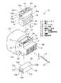
以下、本発明に係る防水コネクタ及び防水処理方法の実施形態について説明する。図1は、防水コネクタ10の外観を示す分解斜視図であり、図2、図3、図4は、防水コネクタ10の内部を示す断面図である。
【0022】
図1及び図2に示すように、防水コネクタ10は、端子11が収容される端子収容室12を有するハウジング13と、このハウジング13の電線引出側の後端部13aに設けられて端子収容室12内をシールするシール部14と、このシール部14に組み付けられる軟質シール材15とを備えている。また、本実施形態の防水コネクタ10は、軟質シール材15に端子11の外径寸法L1より大きい寸法L2の挿通孔16が設けられ、シール部14に軟質シール材15が挿入されるシール材収容空間17が設けられている。さらに、このシール材収容空間17内の軟質シール材15を加圧して挿通孔16を縮小させることで電線18の外周に密着・当接させる加圧部材29がシール部14に設けられている。
【0023】
ハウジング13は、本体19と、この本体19の外側に一体に形成された防水フード部20と、本体19の後端側に一体に設けられた基部21とからなり、基部21の本体19側にシール部14が設けられている。本体19内には、端子収容室12が2段に形成されており、各内壁からは可撓性の係止ランス22がそれぞれ突設されている。
【0024】
また、本体19には、端子収容室12内への端子11の挿入方向に対して交差する方向に沿って移動可能なスペーサ23が仮係止位置に組み付けられている。このスペーサ23は、本係止位置に移動することによって、端子収容室12内に収容されて係止ランス22と係合し、その抜けが阻止された端子11に係止して、端子収容室12内からの端子11の抜けを二重に防止している。また、本体19の相手コネクタとの嵌合面19a側には、スライド部材24が装着されている。このスライド部材24は、本体19側へ移動することによりスペーサ23を仮係止位置から本係止位置に移動させる。
【0025】
上記シール部14は、上下に貫通した矩形断面の貫通孔25が設けられており、貫通孔25の対向する内壁25a、25bには、端子収容室12と基部21の端子導入孔27にそれぞれ連通する端子挿入開口26、28が形成されている。そして、基部21と本体19との間が、軟質シール材15が収容されるシール材収容空間17となっている。
【0026】
軟質シール材15は、ブロック状に形成されて、厚み方向に貫通したスリット状の上記端子挿通孔16、16が2段に形成されている。この端子挿通孔16の幅寸法L2は、上記したように端子11の外径寸法L1より大きく設定されており、端子11が端子挿通孔16内を挿通する場合、挿通孔16の内壁に端子11が摺動することのない程度に形成されている。また、端子挿通孔16は、シール材収容空間17に収容された状態では、端子挿通孔16が端子挿入開口26、28にそれぞれ連通し、基部21の端子導入孔27から挿入された端子11が、端子挿通孔16を挿通した後に、端子収容室12内に容易に挿入できるようになっている。
【0027】
この軟質シール材15は、電線挿通孔16を間に挟んで両側に配置された加圧部材29、29により加圧されて収縮し、電線挿通孔16が縮小することにより電線18の外周に密着・当接する。
【0028】
加圧部材29は、軟質シール材の上面15a又は下面15bに当接する板状の当接底部30の外周から、4つの側壁31a、31a、32a、32aが立ち上がったボックス状に形成され、内部に対角同士を結ぶ補強板35、35がクロスして設けられている。また、側壁32a、32aの外周には係止突起(ただし、図1には片側のみ図示)33、33が設けられている。この係止突起33は、傾斜面33aと垂直面33bとを有し、シール部14の両側壁14a、14aに設けられた矩形状の係止孔34、34に係合することにより、軟質シール材15を加圧した状態に保持する。また、シール部14の上下の開口部分にセットされた状態では、垂直面33b、33bが係止孔34の縁部上に当接する。
【0029】
次に、この防水コネクタ10による防水処理方法について説明する。
【0030】
先ず、図2に示すように、軟質シール材15をシール材収容空間17内にセットする。この場合、軟質シール材15の端子挿通孔16は、端子収容室12側の開口26と連通すると共に、端子導入孔27側の開口28と連通している。この状態から、電線18の端末の端子11を基部21の端子導入孔27内に挿入し、端子挿通孔16内を挿通させた後に、端子収容室12内に収容する。このとき、図3及び図5(a)に示すように、端子11は、端子挿通孔16の内壁に接触することなく、あるいは、触れても端子挿通孔16の内壁を傷つけることなく挿通することができる。
【0031】
端子11を端子収容室12内に収容した状態では、係止ランス22が端子11に係合して端子収容室12内からの抜けが阻止される。また、この状態から、スライド部材24を本体19側に移動させることにより、仮係止位置にあるスペーサ23を本係止位置に移動させて、スペーサ23を端子11に係止する。これにより、端子11は、係止ランス22との係合、スペーサ23との係止により端子収容室12内に二重に係止される。
【0032】
次に、図3、図5(b)に示すように、加圧部材29、29を互いに接近する方向に移動させることによって、軟質シール部材15を加圧すると、端子挿通孔16の内壁が電線18の外周に密着当接する。また、係止突起33が係止孔34に係合することによって、加圧部材29、29が軟質シール材15を加圧した状態が保持される。これにより、電線18の外周と軟質シール材15との間からの水の浸入が阻止される。
【0033】
本実施形態によれば、軟質シール材15に設けた端子挿通孔16が、端子11の外径寸法より大きく設定されているので、端子挿通孔16内に端子11を挿通させても端子11に軟質シール部材15が付着することがない。この結果、相手端子との接続時に絶縁体である軟質シール材15が介在しないので、電気的接続における信頼性を向上することができる。
【0034】
また、端子挿通孔16に端子11を挿通させて端子収容室12内に収容した後に、加圧部材29、29によって軟質シール材15を加圧して電線18の外周に密着当接させることによって、端子収容室12内への水の浸入を防止することができる。
【0035】
さらに、加圧部材29、29を係止孔34と係止突起33によって、軟質シール材15を加圧した状態に保持することによって、シール性能を確実に維持することができる。
【0036】
さらに、端子挿通孔16を端子11が挿通する場合、端子11によって、軟質シール材15を削り取ることがないので、軟質シール材の欠損を防止して、流れ込み量が変化することがないので、シール性能の低下を確実に防止することができる。
【0037】
【発明の効果】
以上説明したように請求項1の発明によれば、シール材収容空間に軟質シール材を収容した状態で、端子を挿通孔内に挿通させて端子収容室内に収容させても、挿通孔が端子の外径より大きく設定されているので、端子に軟質シール材が付着することがない。また、端子によって軟質シール材が削り取られることもない。
【0038】
さらに、軟質シール材は、加圧部材によって加圧されることによって、電線の外周全域に密着・当接することで防水性能を確保することができる。
【0039】
さらに、軟質シール材の両側の加圧部材を互いに接近させることにより、挿通孔断面形状を圧縮する方向に加圧するので、軟質シール材を容易にかつ確実に加圧することができる。
【0040】
請求項2の発明によれば、軟質シール材を加圧した加圧部材による加圧状態を、係止突起を係止孔に挿入・係止して加圧部材をシール部に保持することで維持することができる。
【0041】
請求項3の発明によれば、シール材収容空間内の軟質シール材の挿通孔に電線端末の端子を挿通させて端子収容室内に収容させても、挿通孔が端子の外径より大きく設定されているので端子に軟質シール材が付着することがない。また、軟質シール材を端子が削り取ることもないので、軟質シール材のシール性能の低下を防止することができる。
【図面の簡単な説明】
【図1】本発明に係る防水コネクタを示す分解斜視図である。
【図2】本発明に係る防水コネクタの内部を示し、端子を端子収容室内に収容する前の状態を示す断面図である。
【図3】端子を端子収容室内に収容した状態を示す断面図である。
【図4】軟質シール材を加圧部材で加圧した状態を示す断面図である。
【図5】本発明に係る防水コネクタの内部を示し、(a)は図3のa−a線に沿って切断した断面図、(b)は図4のb−b線に沿って切断した断面図である。
【図6】従来の防水コネクタを示し、(a)は端子を端子収容室内に挿入する前の状態を示す断面図、(b)は防水コネクタに用いられる軟質シール材を示す正面図、(c)は端子を端子収容室内に挿入した状態を示す断面図である。
【符号の説明】
10 防水コネクタ
11 端子
12 端子収容室
13 ハウジング
14 シール部
15 軟質シール材
16 端子挿通孔
17 シール材収容空間
18 電線
29 加圧部材[0001]
TECHNICAL FIELD OF THE INVENTION
The present invention relates to a waterproof connector and a waterproofing method in which a terminal accommodating chamber of a housing is sealed with a soft sealing material.
[0002]
[Prior art]
6 (a), 6 (b) and 6 (c) show a conventional technique using a technique similar to that described in U.S. Pat. No. 4,662,692, JP-A-64-63282, and JP-A-4-101380. 1 shows a
[0003]
Further, the
[0004]
In this
[0005]
From this state, as shown in FIG. 6C, the
[0006]
At this time, since the
[0007]
This prevents water from entering between the outer periphery of the electric wire 4 and the
[0008]
[Problems to be solved by the invention]
By the way, as shown in FIG. 6 (c), when the
[0009]
Further, if the
[0010]
Therefore, the present invention provides a waterproof connector and a waterproofing method capable of preventing the soft sealing material from adhering to the terminal, preventing the soft sealing material from being damaged by the terminal, and preventing the sealing performance from deteriorating. For the purpose of providing.
[0011]
[Means for Solving the Problems]
In order to achieve the above object, an invention according to
[0012]
In this waterproof connector, the insertion hole is set to be larger than the outer diameter of the terminal even when the terminal is inserted into the insertion hole and is accommodated in the terminal accommodation room in a state where the soft sealing material is accommodated in the sealing material accommodation space. Therefore, the soft sealing material does not adhere to the terminals. Further, the soft sealing material is not scraped off by the terminal. Furthermore, the soft sealing material is pressurized by the pressurizing member, so that the soft sealing material comes into close contact with and contacts theentire outer periphery of the electric wire, so that waterproof performance can be secured.
[0013]
Further, the pressure members are provided on both sides of the insertion hole of the soft seal material accommodated in the seal material accommodation space ina direction to compress the cross-sectional shape of the insertion hole , and the pressure members on both sides are provided. The method is characterized in that the soft sealing materials are pressed by approaching each other.
[0014]
In this waterproof connector, the pressurizing members on both sides of the soft seal material are brought close to each other topress in a direction to compress the cross-sectional shape of theinsertion hole ,so that the soft seal material can be easily and reliably pressurized.
[0015]
The invention according to
[0016]
In this waterproof connector, the pressurized state by the pressurizing member pressurizing the soft sealing material is maintained by inserting and locking the locking projection into the locking hole and holding the pressing member in the seal portion.
[0017]
According to a third aspect of the present invention,there is provided a waterproofing method using the waterproof connector according to any one of the first to second aspects, wherein the soft sealing material is accommodated in a sealing material accommodation space of the seal portion. The terminal of the electric wire terminal is inserted through the insertion hole of the soft seal material, accommodated in the terminal accommodating chamber, the soft seal material is pressurized by the pressurizing member, the insertion hole is reduced, and the soft seal material is inserted into the electric wire. It is characterizedby being brought into close contact with the entire outer periphery .
[0018]
In this waterproofing method, even if the insertion hole of the soft sealing material of the sealing material accommodation space by inserting the pin of the wire end is received in the terminal receiving chamber, the insertion holethat is larger than the outer diameter of the pin No soft sealing material adheres to the terminals. Further, since the terminal does not scrape off the soft sealing material, it is possible to prevent the sealing performance of the soft sealing material from deteriorating.
[0020]
In this waterproofing method, the soft sealing material can be pressed easily and reliably by moving the pressing members on both sides in a direction approaching each other.
[0021]
BEST MODE FOR CARRYING OUT THE INVENTION
Hereinafter, embodiments of a waterproof connector and a waterproofing method according to the present invention will be described. FIG. 1 is an exploded perspective view showing the appearance of the
[0022]
As shown in FIGS. 1 and 2, the
[0023]
The
[0024]
Further, a
[0025]
The
[0026]
The
[0027]
The
[0028]
The pressing
[0029]
Next, a waterproofing method using the
[0030]
First, as shown in FIG. 2, the
[0031]
When the terminal 11 is accommodated in the
[0032]
Next, as shown in FIGS. 3 and 5 (b), when the
[0033]
According to the present embodiment, since the
[0034]
Further, after the terminal 11 is inserted into the
[0035]
Furthermore, by maintaining the
[0036]
Further, when the terminal 11 is inserted through the
[0037]
【The invention's effect】
As described above, according to the first aspect of the present invention, even if the terminal is inserted into the insertion hole and accommodated in the terminal accommodating chamber in a state where the soft sealing material is accommodated in the sealing material accommodating space, the insertion hole is Is set larger than the outer diameter of the terminal, so that the soft sealing material does not adhere to the terminal. Further, the soft sealing material is not scraped off by the terminal.
[0038]
Furthermore, the soft sealing material is pressurized by the pressurizing member, so that the soft sealing material comes into close contact with and contacts theentire outer periphery of the electric wire, so that waterproof performance can be secured.
[0039]
Furthermore, since the pressurizing members on both sides of the soft seal material are brought closer to each other, the pressure is applied in the direction of compressing the cross-sectional shape of theinsertion hole ,so that the soft seal material can be pressed easily and reliably.
[0040]
According to thesecond aspect of the present invention, the pressurized state by the pressurizing member pressurizing the soft sealing material is maintained by inserting and locking the locking projection into the locking hole and holding the pressing member in the seal portion. Can be maintained.
[0041]
According to the invention of claim 3, even if the terminal of the electric wire terminal is inserted into the insertion hole of the soft sealing material in the sealing material accommodation space and accommodated in the terminal accommodation room, the insertion hole is set to be larger than the outer diameter of the terminal. since TeiRu soft sealing material does not adhere to the terminal. Further, since the terminal does not scrape off the soft sealing material, it is possible to prevent the sealing performance of the soft sealing material from deteriorating.
[Brief description of the drawings]
FIG. 1 is an exploded perspective view showing a waterproof connector according to the present invention.
FIG. 2 is a cross-sectional view showing the inside of the waterproof connector according to the present invention and showing a state before terminals are accommodated in a terminal accommodating chamber.
FIG. 3 is a cross-sectional view showing a state in which a terminal is housed in a terminal housing chamber.
FIG. 4 is a cross-sectional view showing a state where a soft sealing material is pressed by a pressing member.
5A and 5B show the inside of the waterproof connector according to the present invention, in which FIG. 5A is a cross-sectional view taken along the line aa of FIG. 3, and FIG. 5B is a cross-sectional view taken along the line bb of FIG. It is sectional drawing.
6A and 6B show a conventional waterproof connector, in which FIG. 6A is a cross-sectional view showing a state before a terminal is inserted into a terminal accommodating chamber, FIG. 6B is a front view showing a soft sealing material used in the waterproof connector, and FIG. () Is a sectional view showing a state where the terminal is inserted into the terminal accommodating chamber.
[Explanation of symbols]
DESCRIPTION OF
Claims (3)
Translated fromJapanesePriority Applications (4)
| Application Number | Priority Date | Filing Date | Title |
|---|---|---|---|
| JP08711698AJP3566541B2 (en) | 1998-03-31 | 1998-03-31 | Waterproof connector and waterproofing method |
| EP99105167AEP0948092B1 (en) | 1998-03-31 | 1999-03-30 | Waterproof connector and waterproofing method |
| DE69937082TDE69937082T2 (en) | 1998-03-31 | 1999-03-30 | Waterproof connector and sealing method |
| US09/281,005US6514102B1 (en) | 1998-03-31 | 1999-03-30 | Waterproof connector and waterproofing method |
Applications Claiming Priority (1)
| Application Number | Priority Date | Filing Date | Title |
|---|---|---|---|
| JP08711698AJP3566541B2 (en) | 1998-03-31 | 1998-03-31 | Waterproof connector and waterproofing method |
Publications (2)
| Publication Number | Publication Date |
|---|---|
| JPH11283694A JPH11283694A (en) | 1999-10-15 |
| JP3566541B2true JP3566541B2 (en) | 2004-09-15 |
Family
ID=13905992
Family Applications (1)
| Application Number | Title | Priority Date | Filing Date |
|---|---|---|---|
| JP08711698AExpired - Fee RelatedJP3566541B2 (en) | 1998-03-31 | 1998-03-31 | Waterproof connector and waterproofing method |
Country Status (4)
| Country | Link |
|---|---|
| US (1) | US6514102B1 (en) |
| EP (1) | EP0948092B1 (en) |
| JP (1) | JP3566541B2 (en) |
| DE (1) | DE69937082T2 (en) |
Cited By (4)
| Publication number | Priority date | Publication date | Assignee | Title |
|---|---|---|---|---|
| WO2018123098A1 (en)* | 2016-12-27 | 2018-07-05 | 矢崎総業株式会社 | Terminal connection method |
| WO2018123097A1 (en)* | 2016-12-27 | 2018-07-05 | 矢崎総業株式会社 | Terminal-equipped electric wire and terminal production method |
| JP2018106997A (en)* | 2016-12-27 | 2018-07-05 | 矢崎総業株式会社 | Crimp terminal |
| JP2018106993A (en)* | 2016-12-27 | 2018-07-05 | 矢崎総業株式会社 | Crimp terminal |
Families Citing this family (11)
| Publication number | Priority date | Publication date | Assignee | Title |
|---|---|---|---|---|
| EP1028493B1 (en)* | 1998-06-08 | 2008-07-30 | Harness System Technologies Research, Ltd. | Waterproof connector |
| US6906396B2 (en) | 2002-01-15 | 2005-06-14 | Micron Technology, Inc. | Magnetic shield for integrated circuit packaging |
| JP4529082B2 (en)* | 2005-01-05 | 2010-08-25 | 住友電装株式会社 | connector |
| EP1859512A1 (en)* | 2005-01-19 | 2007-11-28 | Fci | Electric connector for a flat cable provided with improved sealing means |
| WO2007128337A1 (en)* | 2006-05-10 | 2007-11-15 | Fci | Electrical connector |
| GB0625527D0 (en)* | 2006-12-22 | 2007-01-31 | Delphi Tech Inc | Seal for flat electrical conductor |
| JP2010532546A (en) | 2007-06-29 | 2010-10-07 | ザ・パテント・ストア・エルエルシー | Waterproof push-in wire connector |
| PL2228870T3 (en)* | 2009-03-12 | 2011-11-30 | Te Connectivity Germany Gmbh | Electrical connector |
| ITTO20120905A1 (en)* | 2012-10-16 | 2014-04-17 | Tyco Electronics Amp Italia Srl | ELECTRIC CONNECTOR WITH SEALING ELEMENT AND PROCEDURE FOR ASSEMBLY |
| CN205752743U (en)* | 2016-05-06 | 2016-11-30 | 富士康(昆山)电脑接插件有限公司 | Electric connector |
| JP7378896B2 (en)* | 2019-12-06 | 2023-11-14 | 矢崎総業株式会社 | Seal structure |
Family Cites Families (71)
| Publication number | Priority date | Publication date | Assignee | Title |
|---|---|---|---|---|
| DE2116354A1 (en) | 1971-04-03 | 1972-10-19 | Kabel Metallwerke Ghh | Process for the production of an ultrasonically weldable material from polyvinyl chloride |
| FR2243022B1 (en) | 1973-09-10 | 1977-09-23 | Rhone Progil | |
| US4083902A (en) | 1977-01-10 | 1978-04-11 | Raychem Corporation | Method of sealing a connector |
| JPS5498987A (en) | 1978-01-20 | 1979-08-04 | Nissan Motor | Waterproof connector |
| JPS6112621A (en) | 1984-06-27 | 1986-01-21 | Lion Corp | Cataplasma |
| EP0187819B1 (en) | 1984-06-29 | 1988-12-14 | AMP INCORPORATED (a New Jersey corporation) | Retention article for electrical contacts |
| US4662629A (en) | 1984-09-19 | 1987-05-05 | Bartholomew Plovie | Exercise device |
| GB8431301D0 (en)* | 1984-12-12 | 1985-01-23 | Amp Great Britain | Lead sealing assembly |
| US4640567A (en) | 1985-01-30 | 1987-02-03 | Amp Incorporated | Detachable sealed multicontact electrical connector |
| US4662692A (en) | 1985-05-02 | 1987-05-05 | Raychem Corp. | Sealing member |
| US4643506A (en) | 1985-05-17 | 1987-02-17 | Amp Incorporated | Wire seal |
| US4713021A (en)* | 1985-05-17 | 1987-12-15 | Amp Incorporated | Sealed electrical connector and method of using same |
| JPS62188069A (en) | 1986-02-14 | 1987-08-17 | Hitachi Ltd | Image data recording system |
| US4708662A (en) | 1986-06-20 | 1987-11-24 | Amp Incorporated | Connector assembly with pre-staged terminal retainer |
| EP0299797B1 (en) | 1987-07-16 | 1994-12-07 | Raychem Limited | Article for protecting a substrate |
| US4776813A (en)* | 1987-12-08 | 1988-10-11 | Molex Incorporated | Sealed connector assembly |
| JPH0773063B2 (en) | 1988-05-31 | 1995-08-02 | 矢崎総業株式会社 | Crimped terminal conductor coupling structure and method of forming the same |
| US4976634A (en) | 1989-08-31 | 1990-12-11 | Amp Incorporated | Means and method of securing an insert in a shell |
| US4944688A (en) | 1989-09-25 | 1990-07-31 | Amp Incorporated | Programmable sealed connector |
| EP0424887B1 (en) | 1989-10-24 | 1996-04-03 | The Whitaker Corporation | Electrical connector having improved secondary retention means |
| US4979913A (en) | 1989-10-26 | 1990-12-25 | Amp Incorporated | Electrical connector with hinged secondary lock |
| JPH0449480A (en) | 1990-06-19 | 1992-02-18 | Fujitsu Ltd | Bar code reading system |
| JPH0495369A (en) | 1990-08-01 | 1992-03-27 | Yazaki Corp | Electrical connector with terminal fixture |
| JP2533679B2 (en) | 1990-08-17 | 1996-09-11 | 日本碍子株式会社 | Plate-shaped ceramic heater and method for manufacturing the same |
| US5116236A (en) | 1990-11-05 | 1992-05-26 | Molex Incorporated | Electrical connector with terminal position assurance component |
| JP2524946Y2 (en) | 1991-07-10 | 1997-02-05 | 矢崎総業株式会社 | Structure of waterproof female connector housing |
| US5266045A (en) | 1991-10-28 | 1993-11-30 | Yazaki Corporation | Waterproof connector |
| JP3062545B2 (en) | 1991-11-29 | 2000-07-10 | タイコエレクトロニクスアンプ株式会社 | IDC type waterproof connector assembly |
| JP3125198B2 (en) | 1991-12-04 | 2001-01-15 | 本田技研工業株式会社 | Battery temperature control device for electric vehicle |
| US5215635A (en) | 1991-12-13 | 1993-06-01 | General Electric Company | Method for making silicone gels using ultrasonic energy |
| JP2996559B2 (en) | 1992-01-29 | 2000-01-11 | 本田技研工業株式会社 | Electric vehicle charging status display system |
| JP2901110B2 (en) | 1992-05-25 | 1999-06-07 | 矢崎総業株式会社 | Electrical connector with rear holder |
| JP2575393Y2 (en) | 1992-11-11 | 1998-06-25 | 住友電装株式会社 | Waterproof connector |
| JP2567133Y2 (en) | 1992-12-16 | 1998-03-30 | 矢崎総業株式会社 | Shield connector |
| JPH06217412A (en) | 1993-01-14 | 1994-08-05 | Toyota Motor Corp | Battery unit for vehicle |
| JP3240080B2 (en) | 1993-04-09 | 2001-12-17 | 本田技研工業株式会社 | Electric vehicle |
| GB9313281D0 (en) | 1993-06-28 | 1993-08-11 | Amp Gmbh | Sealed insulation displacement connector |
| JP2725758B2 (en) | 1993-10-27 | 1998-03-11 | 矢崎総業株式会社 | Dummy plug for waterproof connector and waterproof connector |
| JP2896737B2 (en) | 1993-12-28 | 1999-05-31 | 矢崎総業株式会社 | connector |
| JP3009122B2 (en) | 1994-03-03 | 2000-02-14 | 矢崎総業株式会社 | Waterproof plug for waterproof connector |
| JP2863083B2 (en) | 1994-04-01 | 1999-03-03 | 矢崎総業株式会社 | Waterproof stopper for connector |
| US5529508A (en) | 1994-04-01 | 1996-06-25 | Raychem Corporation | Sealing member |
| JP3060359B2 (en) | 1994-04-06 | 2000-07-10 | 矢崎総業株式会社 | Electrical connector |
| JPH07298450A (en) | 1994-04-19 | 1995-11-10 | Japan Aviation Electron Ind Ltd | Mounting structure for housing cover for harness |
| JP2921641B2 (en)* | 1994-05-23 | 1999-07-19 | 矢崎総業株式会社 | Waterproof connector |
| US5580264A (en) | 1994-08-09 | 1996-12-03 | Sumitomo Wiring Systems, Ltd. | Waterproofed connector |
| US5554055A (en) | 1994-08-31 | 1996-09-10 | Thomas & Betts Corporation | Electrical connector employing dual locking contact retention |
| US5562477A (en) | 1994-11-02 | 1996-10-08 | Caterpillar Inc. | High vibration electrical connector |
| US5569050A (en) | 1994-12-02 | 1996-10-29 | W. L. Gore & Associates, Inc. | Low-profile, pierce-through connector backshell |
| JPH08186901A (en) | 1994-12-29 | 1996-07-16 | Nissan Motor Co Ltd | Ventilation fan controller |
| US5782657A (en) | 1995-04-13 | 1998-07-21 | The Whitaker Corporation | Electrical connector with secondary lock |
| JPH097676A (en) | 1995-06-23 | 1997-01-10 | Yazaki Corp | Connector terminal locking structure |
| JPH0945376A (en) | 1995-07-26 | 1997-02-14 | Honda Motor Co Ltd | Overdischarge detection device for sealed alkaline secondary battery |
| JP3083070B2 (en) | 1995-08-29 | 2000-09-04 | 矢崎総業株式会社 | Double locking connector |
| JP3230956B2 (en)* | 1995-09-05 | 2001-11-19 | 矢崎総業株式会社 | Waterproof insulation displacement connector |
| JP3140343B2 (en) | 1995-09-14 | 2001-03-05 | 矢崎総業株式会社 | Connector device |
| JPH09106851A (en) | 1995-10-09 | 1997-04-22 | Yazaki Corp | Waterproof connector |
| JP3168396B2 (en) | 1995-11-29 | 2001-05-21 | 矢崎総業株式会社 | Connector with rear holder |
| US5647775A (en) | 1995-12-07 | 1997-07-15 | Molex Incorporated | Electrical connector with terminal locking means |
| WO1997036346A1 (en) | 1996-03-27 | 1997-10-02 | The Whitaker Corporation | Sealed electrical connector |
| JP3511431B2 (en) | 1996-04-01 | 2004-03-29 | カルソニックカンセイ株式会社 | Connector with terminal lock |
| JPH09289057A (en)* | 1996-04-19 | 1997-11-04 | Yazaki Corp | Waterproof connector |
| JPH1060096A (en) | 1996-08-20 | 1998-03-03 | Toshiba Chem Corp | Flame-retardant epoxy resin composition |
| FR2753008B1 (en) | 1996-09-05 | 1998-10-30 | Cinch Connecteurs Sa | ELECTRICAL CONNECTOR CHANNEL SHUTTER |
| US5947774A (en) | 1996-09-13 | 1999-09-07 | Yazaki Corporation | Press-connecting connector |
| JP3593425B2 (en) | 1996-09-13 | 2004-11-24 | 矢崎総業株式会社 | ID connector |
| JP3311619B2 (en) | 1996-12-24 | 2002-08-05 | 矢崎総業株式会社 | Waterproof structure of wire lead-out part and manufacturing method |
| JP3394146B2 (en) | 1996-12-26 | 2003-04-07 | 矢崎総業株式会社 | Connector wire connection structure |
| JP3195263B2 (en) | 1997-01-08 | 2001-08-06 | 矢崎総業株式会社 | Waterproof connector and method of manufacturing the same |
| JP3295329B2 (en) | 1997-01-09 | 2002-06-24 | 矢崎総業株式会社 | Ultrasonic connection terminal and ultrasonic connection structure |
| JP3529972B2 (en) | 1997-03-28 | 2004-05-24 | 矢崎総業株式会社 | Connector housing rear holder lifting prevention structure |
- 1998
- 1998-03-31JPJP08711698Apatent/JP3566541B2/ennot_activeExpired - Fee Related
- 1999
- 1999-03-30USUS09/281,005patent/US6514102B1/ennot_activeExpired - Fee Related
- 1999-03-30DEDE69937082Tpatent/DE69937082T2/ennot_activeExpired - Lifetime
- 1999-03-30EPEP99105167Apatent/EP0948092B1/ennot_activeExpired - Lifetime
Cited By (10)
| Publication number | Priority date | Publication date | Assignee | Title |
|---|---|---|---|---|
| WO2018123098A1 (en)* | 2016-12-27 | 2018-07-05 | 矢崎総業株式会社 | Terminal connection method |
| WO2018123097A1 (en)* | 2016-12-27 | 2018-07-05 | 矢崎総業株式会社 | Terminal-equipped electric wire and terminal production method |
| JP2018106996A (en)* | 2016-12-27 | 2018-07-05 | 矢崎総業株式会社 | Terminal connection method |
| JP2018106995A (en)* | 2016-12-27 | 2018-07-05 | 矢崎総業株式会社 | Electric wire with terminal and terminal manufacturing method |
| JP2018106997A (en)* | 2016-12-27 | 2018-07-05 | 矢崎総業株式会社 | Crimp terminal |
| JP2018106993A (en)* | 2016-12-27 | 2018-07-05 | 矢崎総業株式会社 | Crimp terminal |
| WO2018123099A1 (en)* | 2016-12-27 | 2018-07-05 | 矢崎総業株式会社 | Crimp terminal |
| US10658784B2 (en) | 2016-12-27 | 2020-05-19 | Yazaki Corporation | Crimp terminal |
| US10978824B2 (en) | 2016-12-27 | 2021-04-13 | Yazaki Corporation | Crimp terminal with ridge portion and manufacturing method thereof |
| US11239620B2 (en) | 2016-12-27 | 2022-02-01 | Yazaki Corporation | Terminal connecting method |
Also Published As
| Publication number | Publication date |
|---|---|
| EP0948092A1 (en) | 1999-10-06 |
| DE69937082T2 (en) | 2008-06-12 |
| DE69937082D1 (en) | 2007-10-25 |
| JPH11283694A (en) | 1999-10-15 |
| US6514102B1 (en) | 2003-02-04 |
| EP0948092B1 (en) | 2007-09-12 |
Similar Documents
| Publication | Publication Date | Title |
|---|---|---|
| JP3547988B2 (en) | Waterproof connector and waterproofing method | |
| JP3566541B2 (en) | Waterproof connector and waterproofing method | |
| US4621883A (en) | Electrical connector assembly | |
| JP2725753B2 (en) | Sealing member for waterproof connector | |
| JP2660392B2 (en) | Sealed electrical connector | |
| CN100452548C (en) | Onboard connector | |
| US6053753A (en) | Sealed electrical connector assembly | |
| JP3566540B2 (en) | Waterproof connector | |
| JP3591280B2 (en) | connector | |
| JPH0553155U (en) | Waterproof connector | |
| EP3893334B1 (en) | Connection assembly | |
| JP2001257028A (en) | Connector connection structure | |
| US6520788B2 (en) | Watertight connector and sealing member | |
| US6244897B1 (en) | Watertight connector and a method for mounting a watertight connector | |
| JP3540156B2 (en) | Waterproof connector and method of assembling the waterproof connector | |
| JP3517109B2 (en) | Waterproof connector and method of assembling waterproof connector | |
| JP3283791B2 (en) | Connector and connector manufacturing method | |
| JPH0557772U (en) | Waterproof connector | |
| JP2007042449A (en) | Waterproof connector for flat cable | |
| EP0529463B1 (en) | Seals for an electrical connector | |
| JPH023262Y2 (en) | ||
| AU648988B2 (en) | Wire connector for cable wires, in particular of telecommunication cables | |
| JP2005166293A (en) | Waterproof connector | |
| WO1998049755A1 (en) | Connector protective cover | |
| JP2001035588A (en) | Waterproof connector |
Legal Events
| Date | Code | Title | Description |
|---|---|---|---|
| A131 | Notification of reasons for refusal | Free format text:JAPANESE INTERMEDIATE CODE: A131 Effective date:20040302 | |
| A521 | Written amendment | Free format text:JAPANESE INTERMEDIATE CODE: A523 Effective date:20040506 | |
| TRDD | Decision of grant or rejection written | ||
| A01 | Written decision to grant a patent or to grant a registration (utility model) | Free format text:JAPANESE INTERMEDIATE CODE: A01 Effective date:20040601 | |
| A61 | First payment of annual fees (during grant procedure) | Free format text:JAPANESE INTERMEDIATE CODE: A61 Effective date:20040610 | |
| R150 | Certificate of patent or registration of utility model | Free format text:JAPANESE INTERMEDIATE CODE: R150 | |
| FPAY | Renewal fee payment (event date is renewal date of database) | Free format text:PAYMENT UNTIL: 20080618 Year of fee payment:4 | |
| FPAY | Renewal fee payment (event date is renewal date of database) | Free format text:PAYMENT UNTIL: 20090618 Year of fee payment:5 | |
| FPAY | Renewal fee payment (event date is renewal date of database) | Free format text:PAYMENT UNTIL: 20090618 Year of fee payment:5 | |
| FPAY | Renewal fee payment (event date is renewal date of database) | Free format text:PAYMENT UNTIL: 20100618 Year of fee payment:6 | |
| LAPS | Cancellation because of no payment of annual fees |