JP3559306B2 - Traveling robot device and method of performing assembly work using the device - Google Patents
Traveling robot device and method of performing assembly work using the deviceDownload PDFInfo
- Publication number
- JP3559306B2 JP3559306B2JP10160394AJP10160394AJP3559306B2JP 3559306 B2JP3559306 B2JP 3559306B2JP 10160394 AJP10160394 AJP 10160394AJP 10160394 AJP10160394 AJP 10160394AJP 3559306 B2JP3559306 B2JP 3559306B2
- Authority
- JP
- Japan
- Prior art keywords
- robots
- assembling
- robot
- traveling
- area
- Prior art date
- Legal status (The legal status is an assumption and is not a legal conclusion. Google has not performed a legal analysis and makes no representation as to the accuracy of the status listed.)
- Expired - Fee Related
Links
Images


Classifications
- B—PERFORMING OPERATIONS; TRANSPORTING
- B25—HAND TOOLS; PORTABLE POWER-DRIVEN TOOLS; MANIPULATORS
- B25J—MANIPULATORS; CHAMBERS PROVIDED WITH MANIPULATION DEVICES
- B25J9/00—Programme-controlled manipulators
- B25J9/0084—Programme-controlled manipulators comprising a plurality of manipulators
- B—PERFORMING OPERATIONS; TRANSPORTING
- B25—HAND TOOLS; PORTABLE POWER-DRIVEN TOOLS; MANIPULATORS
- B25J—MANIPULATORS; CHAMBERS PROVIDED WITH MANIPULATION DEVICES
- B25J9/00—Programme-controlled manipulators
- B25J9/0084—Programme-controlled manipulators comprising a plurality of manipulators
- B25J9/0087—Dual arms
- B—PERFORMING OPERATIONS; TRANSPORTING
- B25—HAND TOOLS; PORTABLE POWER-DRIVEN TOOLS; MANIPULATORS
- B25J—MANIPULATORS; CHAMBERS PROVIDED WITH MANIPULATION DEVICES
- B25J9/00—Programme-controlled manipulators
- B25J9/16—Programme controls
- B25J9/1679—Programme controls characterised by the tasks executed
- B25J9/1682—Dual arm manipulator; Coordination of several manipulators
- G—PHYSICS
- G05—CONTROLLING; REGULATING
- G05B—CONTROL OR REGULATING SYSTEMS IN GENERAL; FUNCTIONAL ELEMENTS OF SUCH SYSTEMS; MONITORING OR TESTING ARRANGEMENTS FOR SUCH SYSTEMS OR ELEMENTS
- G05B2219/00—Program-control systems
- G05B2219/30—Nc systems
- G05B2219/39—Robotics, robotics to robotics hand
- G05B2219/39109—Dual arm, multiarm manipulation, object handled in cooperation
- G—PHYSICS
- G05—CONTROLLING; REGULATING
- G05B—CONTROL OR REGULATING SYSTEMS IN GENERAL; FUNCTIONAL ELEMENTS OF SUCH SYSTEMS; MONITORING OR TESTING ARRANGEMENTS FOR SUCH SYSTEMS OR ELEMENTS
- G05B2219/00—Program-control systems
- G05B2219/30—Nc systems
- G05B2219/39—Robotics, robotics to robotics hand
- G05B2219/39468—Changeable hand, tool, code carrier, detector
- G—PHYSICS
- G05—CONTROLLING; REGULATING
- G05B—CONTROL OR REGULATING SYSTEMS IN GENERAL; FUNCTIONAL ELEMENTS OF SUCH SYSTEMS; MONITORING OR TESTING ARRANGEMENTS FOR SUCH SYSTEMS OR ELEMENTS
- G05B2219/00—Program-control systems
- G05B2219/30—Nc systems
- G05B2219/40—Robotics, robotics mapping to robotics vision
- G05B2219/40272—Manipulator on slide, track
- G—PHYSICS
- G05—CONTROLLING; REGULATING
- G05B—CONTROL OR REGULATING SYSTEMS IN GENERAL; FUNCTIONAL ELEMENTS OF SUCH SYSTEMS; MONITORING OR TESTING ARRANGEMENTS FOR SUCH SYSTEMS OR ELEMENTS
- G05B2219/00—Program-control systems
- G05B2219/30—Nc systems
- G05B2219/40—Robotics, robotics mapping to robotics vision
- G05B2219/40307—Two, dual arm robot, arm used synchronously, or each separately, asynchronously
- G—PHYSICS
- G05—CONTROLLING; REGULATING
- G05B—CONTROL OR REGULATING SYSTEMS IN GENERAL; FUNCTIONAL ELEMENTS OF SUCH SYSTEMS; MONITORING OR TESTING ARRANGEMENTS FOR SUCH SYSTEMS OR ELEMENTS
- G05B2219/00—Program-control systems
- G05B2219/30—Nc systems
- G05B2219/45—Nc applications
- G05B2219/45064—Assembly robot
Landscapes
- Engineering & Computer Science (AREA)
- Robotics (AREA)
- Mechanical Engineering (AREA)
- Manipulator (AREA)
- Automatic Assembly (AREA)
- Control Of Position Or Direction (AREA)
- Numerical Control (AREA)
Description
Translated fromJapanese【0001】
【産業上の利用分野】
本願発明は各種部品の組立工程あるいはこれに関連あるいは類似じた工程を含むアセンブリング乃至組立加工作業一般(本願においては、これらを総称して「組立作業」と呼ぶこととする)の自動化、省力化に利用される走行ロボット装置と該装置を用いた組立作業実行方法に関し、特に、2台のロボットの協調動作(双腕ロボット状態)と独立動作(非双腕ロボット状態)の使い分けが可能な走行ロボット装置とこれを用いた組立作業実行方法に関する。
【0002】
【従来の技術】
ロボットを用いて物品の把持・搬送を含む組立作業を実行する場合には、ハンドを装着した2本のロボットアームに協調動作を行なわせる双腕ロボット方式が採用されることが多い。双腕ロボット方式は、2台のロボットを共通の制御手段で制御することによって実現される。このような制御手段としては、2台のロボットを一括制御するロボットコントローラあるいは各ロボットに接続された2台のロボットコントローラを通信回線で接続したものが利用出来る(当出願人に係る特願平5−191649号参照)。
【0003】
ところで、一般に、機械部品の組立作業には複数種の部品が関係し、また、ロボットが遂行しなければならない作業の種類の多様であり、双腕協調を要する作業と独立動作が適している作業とが混在している。例えば、部品供給領域に供給された小型軽量の部品を組立テーブル位置まで運ぶだけの作業であれば単腕ロボットで十分であるが、組立時に各ロボットアームに別個の部品を把持して組み付け工程を実行する場合などには、双腕協調が要求される可能性が高い。
【0004】
また、これら多様に作業の中には2台のロボットが接近乃至密着していなければ実行困難な作業とそうでない作業とが含まれている。即ち、ロボット装置を双腕ロボット状態で動作させる作業では、両ロボットのロボットの運動領域の重なり部分(双腕ロボットの作業領域)を大きくとる為に両ロボットは接近乃至密着している必要があるが、各ロボットを単腕で動作させる作業においては、むしろ両ロボットはある程度離れていた方が、各ロボット個々の作業領域を広くとる上で好都合である。
【0005】
従って、2台のロボットで構成される双腕ロボットを含むロボット装置は、上記したようなような状況に適切に対処し得る能力を備えていることが望まれる。
【0006】
下記(1)〜(5)に列記したように、これまでにも双腕ロボットに関する技術が多々提案されているが、上記対応能力を備えたロボット装置は未提案である。
【0007】
(1)実開平04−2577号、実開平04−2578号、特開平01−310874号、特開平01−310875号、特開平05−92379号、特開平05−301180号の各公報には、マスタスレーブ方式の双腕アームの制御に関する技術が開示されているが、機械的構成に関する言及は無く、組立作業に双腕アームを利用することに関する具体的な記載もなされていない。
【0008】
(2)特開平05−262406号公報には、双腕ロボットに対する教示に関する技術が示されているが、やはり、機械的構成に関する言及が無く、組立作業に双腕アームを利用することに関する具体的な記載もなされていない。
【0009】
(3)実開平05−20882号、特開平02−271402号、特開平05−233056号の各公報には、双腕ロボットの機械的構成に関する記述があり、2台のロボットで双腕ロボットを構成することが示されているが、両ロボットのベースが連結された状態で使用されるものであり、2台のロボットの相対的な位置を変更して多様な作業に対応する技術は開示されていない。
【0010】
(4)特開平01−295773号公報には、2台のロボットを1つの回転台上に連結し、更にこの回転台をガイドレール上で走行させるシステムが開示されているが、このシステムは、2台のロボットを個別にガイドレール上で移動させる形態で使用するものではない。
【0011】
(5)実公平5−46865号公報には、2台のロボットを1つの回転台上に連結し、2台のロボットを同時に回転移動させることが記載されているが、2台のロボットを独立に移動させる形態で使用することに関する具体的な記載は無い。
【0012】
【発明が解決しようとする課題】
上記説明したように、従来の技術においては、2台のロボットを双腕ロボット状態と2機の独立した単腕ロボットとして使い分けることは行なわれておらず、また、双腕アームを用いて組立作業等を実行する際に2台のロボット間の相対的な位置関係は連結されたままでであり、自由な選択が許されていない。このような制約により、従来技術では次のような問題点が生じている。
【0013】
(1)組立作業等において、2台のロボットの協調動作、即ち双腕による協調制御によって、複雑な作業を含む工程を実行する場合、あるいは、部品を所定位置に連結する治具等の使用を出来るだけ少なくしたシステムで作業を遂行しようとした場合には、組み付け対象となる部品はすべて双腕アームが届く範囲に供給しなければならない。
【0014】
これでは、供給された部品によって双腕アームの動作範囲が制限を受けたり、部品を立体的に配置する形で供給する為の大がかりなコンベアシステムを必要とする事態を招くことになり、不利である。
【0015】
また、多くの部品を周辺から供給する必要がある場合には、部品の流れが複雑になる。更に、双腕ロボットの利点を生かして、両ロボットに共通の作業領域を多くしようとすると、個々のロボットの作業領域は狭くなってしまう。逆に、部品供給を容易にする為に、個々の作業領域を広くしようとすると、共通の作業領域が狭くなってしまう。
【0016】
(2)上記公知文献の一部に示されているように、双腕ロボットを構成する2台のロボットを旋回する基台上に搭載してロボットの向きを変え得るシステムを採用することで動作領域の拡張を図り、供給部品の分散配置をある程度実現することが可能になるが、このようなシステムにおいては、部品供給の流れが求心的にならざるを得ず、供給ラインを含めた配置の自由度が乏しくなる。また、2本の腕が常に同じ方向にしか向かず、部品搬送の効率が悪い。
【0017】
(3)双腕ロボットを走行軌道上に搭載して走行させるシステムを採用すれば部品の分散配置が可能になるが、2本の腕を走行軌道上で個別に指定された位置に移動させることが出来ないので、作業効率に限界がある。
【0018】
以上のような問題点(1)〜(3)の他にハンド交換に関連した次の問題点(4)がある。
(4)双腕ロボットを利用して組立作業等を実行する場合には、ロボットに装着するハンドを必要に応じて交換しながら各工程の作業を進めることによって、多くの工程をその双腕ロボットに集約して割り当てることが可能となり、作業効率が改善される。しかし、2台のロボットの双腕に使用するハンドを各ロボットの動作領域内に配置すると、そのハンドの為に動作領域が制限を受けて狭められる。
【0019】
また、ハンド交換用に、工作機械におけるタレットの様なインデックス(位置割り出し)機構を備えたテーブルにハンドを装備して交換用に供給することも考えられるが、インデックス動作の制御とロボットの動作の制御が独立して行なわれることになり、作業効率が良くない。
【0020】
本願発明の目的は、これらの問題点を解決することが出来る走行ロボット装置を提供し、また、該走行ロボット装置を使用して組立作業を実行する方法を併せて提案したものである。
【0021】
【課題を解決するための手段】
本願発明は、上記課題を解決し得る走行ロボット装置の基本構成として、請求項1に記載された走行ロボット装置を提案したものである。
【0022】
また、複数系列の組立対象物の供給経路を設定した場合の基本構成として、請求項2に記載された走行ロボット装置を提案したものである。
【0023】
更に、ハンド交換を考慮に入れた構成として、請求項3に記載された走行ロボット装置を提案したものである。
【0024】
そして、以上の各構成を有する走行ロボット装置による作業実行時に大きな反力を受けることを想定した付加構成要件として、請求項4及び請求項5に記載された構成を提案したものである。
【0025】
一方、上記2系列の組立対象物供給経路に対応した型の走行ロボット装置を用いて組立作業を実行する方法としては、請求項6に記載された方法を提案したものである。
【0026】
また、ハンド交換、2台のロボット相互の機械的連結あるいは走行軌道基部への一括固定を含む上記方法として、請求項8に記載された方法並びに請求項9に記載された方法を併せて提案したものである。
【0027】
なお、これら方法を規定した請求項6〜請求項9の文言において、各「段階」は記載順序の通りのシーケンスを必ずしも意味するものでなく、作業の種類によっては順不同に実行されることを許容するものである。例えば、ハンド交換、各機械的連結手段の作動状態への切換は、作業内容に適合したフェイズ乃至タイミングで実行される性質のものである。
【0028】
【作用】
本願発明の走行ロボット装置においては、組立対象物が供給される領域と組立作業が実行される領域の間に1本の共通ロボット走行軌道または互いに平行関係にある2本のロボット走行軌道が設けられる。共通のロボット走行軌道あるいは2本の平行ロボット走行軌道の各々は、1本または2本以上のガイドレールで構成される。即ち、「ロボット走行軌道」を数える単位はガイドレールの本数を必ずしも意味するものではない。
【0029】
1本の共通ロボット走行軌道が設定される場合には、この共通ロボット走行軌道上に2台のロボットが搭載される。また、互いに平行関係にある2本のロボット走行軌道上が設定される場合には、各ロボット走行軌道に1台づつのロボットが搭載される。後者の場合、両ロボット走行軌道間の距離は、少なくとも両ロボットの協調動作が可能な程度に小さく選択される。
【0030】
これら2台のロボットの走行動作、並びにそれ以外のロボット動作(以下、単に「ロボット動作」と言う。は、共通した制御手段によって制御される。この制御手段は、2台のロボットの制御系統を一括してバス結合で統括したロボットコントローラで構成することが出来るが、独立動作時(非協調状態)には各ロボット用のロボットコントローラとして使用される2台のロボットコントローラを通信回線で結合したもので構成しても良い。
【0031】
制御手段は、2台のロボットの走行軌道上における位置を独立に制御することも出来るし、2台のロボットの動作を独立に制御することも出来る。また、2台のロボットのロボット走行軌道上における相対的な位置関係を一定に保つように制御しながら2台のロボットに協調動作を行なわせることも出来る。
【0032】
機械部品等の組立対象物は、通常2系列以上の供給経路を介して供給されるから、各供給系列にロボットの一方を割り当てる形態で、供給された組立対象物の搬送工程を実行することが出来る。組立対象物は、通常、ロボット走行軌道を挟んで存在する組立作業領域内に配置された組立テーブル上まで搬送される。この作業は、2台のロボットの独立制御(非双腕ロボット状態)で実行されることが普通であるが、場合によっては、協調動作によっても構わない。
【0033】
組立作業に必要な部品が組立テーブルに運ばれると、対象物順序に適合した作業のシーケンスに従って、組立工程が実行される。この工程についても、独立動作と協調動作が適宜使い分けられる。
いずれの作業においても、2台のロボットを協調動作させる場合には、2台のロボットのロボット走行軌道上の位置関係は不変に保たれる。
【0034】
また、走行ロボット装置をハンド交換に効率的に対処し得るものとする為には、少なくとも2系列の供給経路に挟まれた領域内(3系列以上の供給経路がある場合には、その中央付近)に、タレット型ハンド置き台のような動的なハンド置き台手段が設置される。このハンド置き台の制御についても、2台のロボットの共通の制御手段によって行なわれる。具体的には、例えば、タレット型ハンド置き台の回転駆動を該制御手段によって制御されるサーボモータによって行なうようにすれば良い。
【0035】
本願発明の一形態によれば、走行ロボット装置には、組立対象物が重量物である場合などには、作業時にロボットを反力による悪影響から守る為に、2台のロボットを前記ロボット軌道上で相互に連結する機械的連結手段、あるいは、2台のロボットをロボット軌道基部に対して一括して固定する機械的結合手段が設けられる。
【0036】
これらの機械的連結手段は、作動状態と非作動状態の切換が可能であり、その切換制御も、2台のロボットを制御する制御する制御手段によって行なわれる。具体的には、例えばロボットコントローラからの指令に従って電気的空気圧手段あるいは電磁的付勢手段に結合されたクランプ部材を作動位置と非作動位置の間で切換移動させることによって、作動状態と非作動状態の切換が行なわれる。
【0037】
これらの機械的連結手段が作動状態とされるのは、協調作業時である場合が一般的であると考えられるが、場合によっては、独立作業時に作動させることも有り得る。
【0038】
なお、2台のロボットを協調動作させて双腕ロボット状態を実現させる制御方法自体には、特に制限は無く、これまでに提案されているマスタスレーブアーム方式の制御方式を適宜利用することが出来る。
【0039】
これら諸制御を含めて、2台のロボット共通の制御手段を、2台のロボットの制御系統を一括してバス結合で統括したロボットコントローラで構成した場合、及び、各ロボット用のロボットコントローラに所属した2台のロボットコントローラを通信回線で結合したもので構成した場合、各々のケースについての協調動作制御の詳細例については、当出願人に係る前出の特願平5−191649号に添付された明細書に記されている。
【0040】
【実施例】
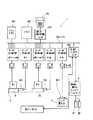
図1は、本願発明に従った走行ロボット装置の全体構成を要部ブロック図で示したものである。
【0041】
走行ロボット装置を含むシステム全体は大別して、ロボットコントローラ1、ロボット走行軌道(走行軸)2、該ロボット走行軌道上に搭載された2台のロボットR1,R2、供給・搬出コンベアコントローラ3、供給・搬出各コンベア31,32、回転式ハンド置き台4で構成されている。また、必要に応じて連結装置とそのエア駆動部KL1及び/または対基部結合装置とそのエア駆動部KL2が装備される。
【0042】
ロボットコントローラ1は、システム全体の制御装置を兼ねており、中央演算処理装置(メインCPU、以下単にCPUと言う。)101を有し、該CPU101には、RAM及びROMからなるメモリ102、運動の教示・座標設定等を行う為の教示操作盤104に接続された教示操作盤用インターフェイス103、供給・搬出コンベアコントローラ3に接続された入出力インターフェイス105及びサーボ制御部#1〜#15がバス106を介して接続されている。
【0043】
各サーボアンプを介して、サーボ制御部#1〜#6はロボットR1の各軸モータに接続され、サーボ制御部#8〜#13はロボットR2の各軸モータに接続されている。また、サーボ制御部#7はロボットR1の走行台1の駆動モータM1に接続され、サーボ制御部#14はロボットR2の走行台2の駆動モータM2に接続されている。更に、サーボ制御部#14は回転式ハンド置き台4の駆動軸を減速機構を介して駆動するモータM3に接続されている。
【0044】
連結装置とそのエア駆動部KL1及び/または対基部結合装置とそのエア駆動部KL2が装備される場合には、エア駆動部KL1及び/またはエア駆動部KL2が入出力インターフェイス105に接続される。
【0045】
本実施例においては、ロボットR1,R2の独立制御(走行制御を含む)、双腕協調制御、回転式ハンド置き台4との協調制御等は、ロボットコントローラ1のメモリ102に格納された動作プログラムに従って、メインCPU101によって統括的に遂行される。また、エア駆動部KL1及び/またはエア駆動部KL2の作動/非作動状態の切換制御や供給・搬出コンベアコントローラとの各種信号授受は、CPU101の制御の下に、入出力インターフェイス105を介して行なわれる。
【0046】
なお、既述したように、装置全体を統括制御する制御手段は、必ずしも本例のように両ロボットのロボットアーム各軸、走行軸等をバス結合で統括したロボットコントローラで構成する必要はない。例えば、独立動作時(非協調状態)には各ロボット用のロボットコントローラとして使用される2台のロボットコントローラを通信回線で結合したもので構成しても良い。その場合には、図1におけるサーボ制御部の数を必要数に減じ、バス106に通信インターフェイスを接続したロボットコントローラ2台を使用することが出来る。
【0047】
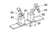
図2は、本願発明に従った走行ロボット装置の全体構成を要部外観図で示したもので、(1)はロボットR1,R2を密着させての双腕協調時、(2)はロボットR1,R2を離隔させての独立動作時の外観を表わしている。
【0048】
また、図3は図2(1)に対応した斜視図で、2台のロボットが互いに近接した位置で双腕協調動作中にある状況を概念的に表わし、図4は図2(1)と図2(2)の中間的状態に対応した斜視図で、2台のロボットが、図3の状態から若干離れた状況を概念的に表わしている。更に、図5は図2(2)に対応した斜視図で、2台のロボットが、図3の状態から図4の状態を経て、完全に離れて独立動作で作業を行なう態勢にある状況を概念的に表わしている。
【0049】
これらの図を参照して、先ず、システム全体のレイアウトについて説明すると、ガイドレール状のロボット走行軌道2には、ボールネジ機構等公知の走行軸機構を介して各走行台10,20が走行可能に取り付けられており、各走行台上にはロボットR1,R2のベースB1,B2が固定されている。ロボットR1,R2は必ずしも同型、同サイズのものであるとは限らず、例えば、立体的な作業をやり易くする為に、ベースB1,B2の高さが異なる2機のロボットを使用することが出来る。また、ベースB1,B2の内部を給電用ケーブル、信号ケーブル等(図示省略)の収容に利用しても良い。
【0050】
ロボット走行軌道2の一方側には、2つの供給系列群SP1,SP2に分かれた配置で多数の供給コンベア31の各供給端が設けられている。
【0051】
各コンベアには、種々の組立部品W1 〜Wn 多数載置されており、ロボットによる組立作業の進行に応じて次々とロボットR1,R2による把持位置に供給される。各コンベアの延在方向は、ロボット走行軌道2に対して交差(ここでは直交)しているので、いずれの供給端もロボット走行軌道2の近傍領域に沿って位置することになる。
【0052】
供給系列群SP1とSP2に属するコンベア列の間には、回転式ハンド置き台4が配置され、両ロボットR1,R2が随時容易にアクセス出来るようになっている。回転式ハンド置き台4上には、ハンドマガジンMGが設けられ、種々のハンド(例えば、把持ハンド、ネジ締めハンドなど)が収容されている。
【0053】
この回転式ハンド置き台4の位置は、ロボット走行軌道2の長さ方向のほぼ中間点位置に対応している。そして、ロボット走行軌道2を挟んで回転式ハンド置き台4と対応した位置には組立テーブルTBが設けられており、その近傍には組立作業を終えた完成ユニット品Wを搬出する搬出コンベア32が配置されている。
【0054】
各ロボットR1,R2のアーム先端部には次に行なう作業工程の遂行に適したハンドH1,H2が、公知のハンド交換機構を含む装着部(図示省略)を介して装着されている。ハンド交換の必要がある場合には、ロボットR1またはR2を回転式ハンド置き台4の近くに走行及び移動させ、ロボットR1またはR2と回転式ハンド置き台4を協調動作させながら、ハンド交換機構を介してハンド交換を行なう。
【0055】
このように本願発明の走行ロボット装置を使用すると、組立作業システム全体のレイアウトが極めてコンパクトにまとめられ、しかも、各ロボットによってアクセスされる必要のあるいずれの要素も、ロボット走行軌道2の中央部を中心にロボット走行軌道2に沿って配列されることになるので、作業効率を高める上で極めて有利である。
【0056】
一般に、ロボットR1,R2による双腕協調動作は、ロボット走行軌道2上におけるロボットR1,R2間の間隔を一定に保った状態で行なわれる。この間隔は自由に選択可能である。図3では、両ロボットのベースB1,B2を密着させた状態で双腕協調動作が行なわれている例を示している。このような双腕協調動作は、組立テーブルTB上における組立作業の遂行に多く利用される。なお、図3〜図5において、把持部品の図示は省略されている。
【0057】
今、仮に図3の状態で、組立テーブルTB上における双腕協調動作による1工程が終了し、次の部品群(W1 〜Wn )を組み立てるステップに移行しようとする場合を想定する。本願発明の走行ロボット装置の典型的な組立作業遂行形態に従えば、ロボットR1,R2はここで次の部品群(W1 〜Wn )から必要な部品を組立テーブルTB上に搬送する為に、一旦、双腕協調状態を解除し、各ロボットR1,R2を独立に走行させ、図4の状態を経て、図5の状態とする。
【0058】
図3(2)に示された外観に対応したこの図5の状態では、両ロボットR1,R2は完全に離れて独立動作で作業を行なう態勢にあり、その位置は各分担された供給系列SP1,SP2のコンベア供給端の近傍にある。
【0059】
各ロボットR1,R2は、図5乃至図3(2)に示された位置で、必要な部品を把持し、組立テーブルTBまで搬送する。次の工程に関与する2個またはそれ以上の部品が組立テーブルTB上に用意された時点で、再度ロボットR1,R2を図4の状態を経て図3の双腕協調状態に復帰させ、組立作業を組立テーブルTB上で実行する。組立作業が終了したユニット完成品は、ロボットコントローラからの指令によって制御される搬出コンベア32上に載置され、次工程へ送り出される。
【0060】
以上が本願発明の走行ロボット装置を用いた典型的な組立作業実行手順であるが、独立動作、協調動作を使い分け及びロボットの走行移動とアームの運動によるロボット移動の使い分け等を含む作業シーケンスの具体的内容は実際の作業内容に即して作成された一連の動作プログラムよって定められるものである。 さて、一般に、組立工程(例えば、ネジ締め)におけるロボット動作には高い精度が要求されることが多いから、上記図3に示したような密着状態で双腕協調動作による組立工程を遂行する際には、ロボットが反力によって不安定になることを極力避けることが望ましい。
図6及び図7は、この課題を解決する為に提案されたロボット連結装置及び対基部結合装置の実施例を表わしている。
【0061】
先ず、図6にはエア駆動により2台の走行台部分を連結する連結装置の一例の概略構成が示されている。連結装置は両走行台10,20の最下部の符号Fで示した部分に設けられている。図には、この領域Fを拡大した様子が併記されている。
【0062】
この拡大図を参照すると、連結装置は一方の走行台20上に設けられたエアシリンダ21、ガイドブッシュ22を備え、連結バー24のガイドピン23がガイドブッシュ22内に挿入されている。また、他方の走行台10側には、連結ブッシュ11が設けられている。エアシリンダ21には、クランプ時及びクランプ解除時にエア供給を行なう為のエア供給ホース26,27が接続されている。
【0063】
図2(1)あるいは図3に示したようなロボット密着時には、ロボットコントローラからの指令によって、図示しないエア供給源からエア供給ホース26を介してエア供給が行なわれ、双方向矢印の下向き方向に空気圧によって連結バー24が移動し、ガイドピン23、連結ピン25が各々ガイドブッシュ22と連結ブッシュ11内に嵌入される。これによって、両ロボットR1,R2の機械的な連結が実現されるから、作業中に反力を受けてもロボットが不安定になること避けられる。
【0064】
ロボットR1,R2を離間させ、連結状態を解除して、図3の状態から図4、図5の状態への移行する際には、ロボットコントローラからの指令によって、図示しないエア供給源からエア供給ホース27を介してエア供給が行なわれ、空気圧によって連結バー24が双方向矢印の上向き方向に移動し、ガイドピン23、連結ピン25が各々ガイドブッシュ22と連結ブッシュ11から離脱する。これによって、両ロボットR1,R2の機械的な連結が解除され、ロボット走行軌道2上の独立走行が可能な状態となる。
【0065】
次に、図7にはエア駆動により2台の走行台部分をロボット走行軌道2の基部(ここでは、床面ベース)に固定する結合装置の一例の概略構成が示されている。結合装置は両走行台10,20の最下部の符号Gで示した付近の床面ベース上に設けられている。図には、この領域Gを拡大した様子が併記されている。
【0066】
この拡大図を参照すると、結合装置は床面ベースに対して固設されたV字ピンベース51と該V字ピンベースに対して水平方向(双方向矢印で指示)にスライド可能に取り付けられたV字ピン52,53を備えている。
【0067】
V字ピン52,53に対向した走行台10,20の各部分には、これらのピンを受容するV字状凹部19,29が形成されている。また、V字ピンベース51には、図6に示した連結装置の場合と同様に、エア供給ホースが接続されている(図示は省略)。
【0068】
図2(1)あるいは図3に示したようなロボット密着時には、ロボットコントローラからの指令によって、図示しないエア供給源からエア供給ホースを介してエア供給が行なわれ、V字ピン52,53が同時にV字状凹部19,29内に受容・係合される。これによって、両ロボットR1,R2が一括して床面ベースに対して固定されるから、作業中に反力を受けてもロボットが不安定になることが避けられる。
【0069】
ロボットR1,R2を離間させ、床面ベースへの固定結合状態を解除して、図3の状態から図4、図5の状態への移行する際には、ロボットコントローラからの指令によって、図示しないエア供給源からの結合解除用のエア供給によってV字ピン52,53がV字状凹部19,29らら離脱する。これによって、両ロボットR1,R2の床面ベースに対する機械的な結合が解除され、ロボット走行軌道2上の独立走行が可能な状態となる。
【0070】
最後に、作業開始前〜終了後までのいずれかの時点において、ロボットハンドの交換を行なう場合のロボットR1またはR2と回転式ハンド置き台4の協調動作について説明する。
図8は、ロボットR1またはR2が、現在装着してハンドHを、回転式ハンド置き台4のハンドマガジン内に準備されたハンドH’に交換する場合を例にとって、ロボットと回転式置き台の協調動作の各段階の推移を概念的に表わした図である。ここでは、符号S1〜S7で指示された各段階別に協調動作の概略を説明する。図中羽根付矢印はハンド置き台4の回転を表わし、羽根無し矢印はロボットアームの動きを表わしている。これらの動きは、いずれもロボットコントローラによるロボット各軸モータ及び回転式ハンド置き台4を駆動するサーボモータM3の制御によって統括的に行なわれる。なお、二重線矢印は、動作段階の推移を表わしている。
【0071】
(S1);回転式ハンド置き台4は、ハンドHの置き位置がロボット(R1またはR2、以下略。)に近づくように回転する。一方、ハンドHが回転式ハンド置き台4に近づき、ハンドHの置き位置に形成されたハンド保持溝Cに正対する位置で両者が接近遭遇するようにロボットを動作させる。
【0072】
(S2);ハンドHとハンド保持溝Cが近接正対する状態になったら、ハンド交換の為の回転式ハンド置き台4の回転方向を決定する。この回転方向は、通常はハンドHとH’の置き位置間の角度間隔が長くならない方向(角度間隔が180度以下となる方向)と一致するように選ばれる。
【0073】
(S3);回転方向が決定したら、回転式ハンド置き台4はその方向へ回転を始める。ロボットには、この回転に追従した動きに、回転式ハンド置き台4の中心へ向かう運動を重畳した動作を行わせ、ハンドHをハンド保持溝C内へはめ込む。
【0074】
(S4);ロボットは、ハンドHを取り外した時点で、回転式ハンド置き台4への追従動作を中止し、次に装着するハンドH’の位置へ移動する。この時、回転式ハンド置き台4は回転を続行しているので、回転式ハンド置き台4の回転速度とロボット手首部の移動速度に基づいて、次に追従動作を開始すべき位置を算出し、その点へ向かって移動する。(ハンド置き位置の回転半径をr、ハンドH,H’の置き位置間の中心角をφ、回転式ハンド置き台の回転速度をω、ロボットの移動速度をv、置き位置の描く円弧上の任意の位置をMとして、ハンドH位置から位置Mへの直線移動所要時間t1 及び、ハンドH’位置から位置Mへの所要回転時間t2 を計算し、t1 =t2 が成立するような位置Mへロボット手首部を移動させる。)。
【0075】
(S5);位置Mへ到達した状態を表わしている。
【0076】
(S6);位置Mより、ロボットは回転式ハンド置き台4に追従動作を行いながら、ハンドH’を装着する。
【0077】
(S7);ハンドH’を装着したら、ロボットは回転式ハンド置き台4から離れ、追従動作を中止する。以上でハンドHからH’への交換が(協調動作)が完了したことになる。以後、ハンドH’を装着した状態で、次の動作へ移行する。
【0078】
以上、1本の共通のロボット走行軌道上に2台のロボットを搭載した実施例について説明を行なったが、上記実施例に関連した説明に含まれる技術事項は、平行に配置された2本のロボット走行軌道上に1台づつロボットを搭載した構成に対しても、ロボット連結装置(図6参照)や対基部結合装置(図7参照)に若干の設計的変更が必要な他は、特に変更を要することなくほぼそのまま成立することは言うまでもない。
【0079】
【発明の効果】
以上詳述したように、本願発明によれば、2台のロボットが、両ロボットに共通したロボット走行軌道または互いに平行関係にある2本のロボット走行軌道上に搭載され、「2台の走行ロボットとしての独立動作」と「2台のロボットを一定の位置関係に保っての協調動作(双腕ロボット状態)」のいずれもが可能とされている。従って、独立動作ロボットとして、各ロボットに独自の搬送作業等を効率的に行なわせることが出来ると同時に、2台のロボットの密着乃至接近状態を維持しながら協調双腕動作によって、複雑な組立作業等を行なわせることが出来る。即ち、2台の単腕の走行ロボットの利点と、1台の双腕走行ロボットの利点を合わせ持った走行ロボット装置が提供される。
【0080】
また、実行作業の種類に応じて、双腕動作時においても2台のロボットの相対位置を選択出来るから、双腕間距離が可変な双腕ロボットとしての機能を有している。
【0081】
更に、走行軌道に沿った広がりのある部分に、各ロボットの動作領域が存在するので、そこに複数系列の経路を介して組立部品等を供給することが可能であり、
部品の種類、数、サイズ、形状等に応じたコンベアを配置して、コンベアの配列幅をカバー出来る長さを有する走行軌道を用意すれば、供給系列数が増加してもシステム構成に支障を来さない。また、ロボット側の制約の為に、供給部品の流れを無理に変更する必要が生じない。
【0082】
組立テーブルの配置に関しても、作業効率を考えて最適の位置に設定することが出来る。例えば、走行軌道を挟んでその延在方向中央付近に、供給コンベアと組立テーブルを対向配置することにより、各供給コンベアの供給端から組立テーブルまでの距離がほぼ一定とし、独立走行ロボットとして動作した場合の作業効率を高めることが出来る。
【0083】
ロボット走行軌道を挟んで供給領域と組立作業領域を設け、供給コンベアと組立テーブルを配置したレイアウトは、前段工程あるいは後続工程との円滑な接続が容易であり、製造ラインの流れを作り出す上で有利である。
【0084】
ハンド交換に対処する際にも、複数系列の供給経路に挟まれた領域内(3系列以上の供給経路がある場合には、その中央付近)に、タレット型ハンド置き台のような動的なハンド置き台手段を設置し、これをロボット制御手段によって制御される軸で駆動することが出来るから、ハンド交換時にハンド置き台とロボットとを協調動作させることも可能である。従って、ハンド交換が迅速的確に実行される。
【0085】
そして、本願発明の一形態においては、組立対象物に重量物が含まれる場合などに想定される作業時の反力による悪影響からロボットを守る為に、2台のロボットを前記ロボット軌道上で相互に連結する機械的連結手段、あるいは、2台のロボットをロボット軌道基部に対して一括して連結する機械的連結手段を装備させ、これらの機械的連結手段あるいは結合手段の作動状態と非作動状態の切換を2台のロボットを制御する制御手段によって遂行させ得る構成を採用した。これにより、双腕協調作業による重量物に対する作業等反力を受ける作業についても、ロボットを安定した状態で実行させることが可能となった。
【図面の簡単な説明】
【図1】
本願発明に従った走行ロボット装置の全体構成を要部ブロック図で示したものである。
【図2】
本願発明に従った走行ロボット装置の全体構成を要部外観図で示したもので、(1)はロボットR1,R2を密着させての双腕協調時、(2)はロボットR1,R2を離隔させての独立動作時の外観を表わしている。
【図3】
図2(1)に対応した斜視図で、2台のロボットが互いに近接した位置で双腕協調動作中にある状況を概念的に表わしている。
【図4】
図2(1)と図2(2)の中間的状態に対応した斜視図で、2台のロボットが、図3の状態から若干離れた状況を概念的に表わしている。
【図5】
図2(2)に対応した斜視図で、2台のロボットが、図3の状態から図4の状態を経て、完全に離れて独立動作で作業を行なう態勢にある状況を概念的に表わしている。
【図6】
2台のロボットの走行台部分を連結する連結装置の実施例を表わした模式図であり、連結装置部分の拡大図が併記されている。
【図7】
2台のロボットの走行台部分をロボット走行軌道の基部に固定する結合装置の実施例を表わした模式図であり、結合装置部分の拡大図が併記されている。
【図8】
ロボットが、現在装着してハンドHを、回転式ハンド置き台のハンドマガジン内に準備されたハンドH’に交換する場合を例にとって、ロボットと回転式置き台の協調動作の各段階の推移を概念的に表わした図である。
【符号の説明】
1 ロボットコントローラ
2 ロボット走行軌道(走行軸)
3 供給・搬出コンベアコントローラ
4 回転式ハンド置き台
10,20 走行台
11 連結ブッシュ
19,29 V字状凹部
21 エアシリンダ
22 ガイドブッシュ
23 ガイドピン
24 連結バー
25 連結ピン
26,27 エア供給ホース
31 供給コンベア
32 搬出コンベア
51 V字ピンベース
52,53 V字ピン
101 中央演算処理装置(メインCPU)
102 メモリ
103 教示操作盤用インターフェイス
104 教示操作盤
105 入出力インターフェイス
106 バス
H1,H2 ハンド
KL1 連結装置エア駆動部
KL2 対基部固定装置エア駆動部
M1,M2 走行軸駆動モータ
M3 回転式ハンド置き台駆動モータ
MG ハンドマガジン
R1,R2 ロボット
SP1,SP2 供給コンベア列(供給系列群)
TB 組立テーブル
W1 〜Wn 供給部品
W ユニット完成品[0001]
[Industrial applications]
The present invention is an automation and labor-saving of assembling or assembling processing in general (in the present application, these are collectively referred to as "assembly work") including assembling steps of various parts or steps related to or similar thereto. The present invention relates to a traveling robot device used for construction and an assembling work execution method using the device, and in particular, it is possible to selectively use two robots in a cooperative operation (dual-arm robot state) and an independent operation (non-dual-arm robot state). The present invention relates to a traveling robot device and a method of performing an assembly operation using the same.
[0002]
[Prior art]
When performing an assembling operation including gripping / transporting of an article using a robot, a dual-arm robot system in which two robot arms equipped with hands perform a cooperative operation is often adopted. The dual-arm robot system is realized by controlling two robots with common control means. As such a control means, a robot controller for controlling two robots at once or a robot controller connected to two robots connected to each robot via a communication line can be used (Japanese Patent Application No. Hei 5 (1993) -A1). 191649).
[0003]
By the way, in general, a plurality of types of parts are involved in assembling mechanical parts, and there are a variety of types of tasks that a robot must perform, and tasks that require dual-arm coordination and tasks that are suitable for independent operation And are mixed. For example, a single-arm robot is sufficient to carry small and lightweight parts supplied to the parts supply area to the assembly table position.However, during assembly, separate parts are held by each robot arm to perform the assembly process. For example, there is a high possibility that dual-arm cooperation is required.
[0004]
In addition, these various tasks include tasks that are difficult to perform if the two robots do not approach or are in close contact, and tasks that are not. That is, in the operation of operating the robot apparatus in the state of the double-armed robot, the two robots need to be close to or close to each other in order to increase the overlapping area (working area of the double-armed robot) of the motion areas of the robots. However, in the operation of operating each robot with a single arm, it is more convenient for the two robots to be apart from each other to some extent in order to increase the work area of each robot.
[0005]
Therefore, it is desired that a robot device including a dual-arm robot composed of two robots has an ability to appropriately cope with the above-described situation.
[0006]
As listed in the following (1) to (5), various technologies relating to a dual-arm robot have been proposed so far, but a robot device having the above-mentioned capability has not been proposed yet.
[0007]
(1) JP-A-04-2577, JP-A-04-2578, JP-A-01-310874, JP-A-01-310875, JP-A-05-92379, JP-A-05-301180, Although a technique relating to control of a master-slave dual-arm arm is disclosed, there is no mention of a mechanical configuration, and there is no specific description relating to the use of the dual-arm arm for assembly work.
[0008]
(2) Japanese Unexamined Patent Publication No. 05-262406 discloses a technique relating to teaching to a double-armed robot, but there is also no mention of a mechanical configuration, and specifics relating to the use of a double-armed arm for assembly work. There is no description.
[0009]
(3) JP-A-05-20882, JP-A-02-271402, and JP-A-05-2333056 each describe a mechanical configuration of a dual-arm robot. Although the configuration is shown, the two robots are used in a state where their bases are connected, and a technique for changing the relative positions of the two robots and corresponding to various tasks is disclosed. Not.
[0010]
(4) Japanese Patent Application Laid-Open No. H01-295773 discloses a system in which two robots are connected on one turntable and the turntable travels on a guide rail. It is not used in a form in which two robots are individually moved on a guide rail.
[0011]
(5) Japanese Utility Model Publication No. 5-46865 describes that two robots are connected on one turntable and the two robots are simultaneously rotated and moved. However, the two robots are independent. There is no specific description regarding use in the form of being moved to
[0012]
[Problems to be solved by the invention]
As described above, in the prior art, the two robots are not properly used as a dual-arm robot and as two independent single-arm robots. The relative positional relationship between the two robots is still connected when executing the operation, and free selection is not allowed. Due to such a restriction, the following problems occur in the related art.
[0013]
(1) In an assembly operation or the like, when a process including a complicated operation is executed by a cooperative operation of two robots, that is, a cooperative control by two arms, or use of a jig or the like for connecting parts to a predetermined position. If you want to work on a system that is as small as possible, all parts to be assembled must be supplied within reach of the dual arm.
[0014]
In this case, the range of operation of the double-armed arm is restricted by the supplied parts, or a large-scale conveyor system for supplying the parts in a three-dimensional arrangement is required. is there.
[0015]
Also, when many parts need to be supplied from the periphery, the flow of the parts becomes complicated. Further, if an attempt is made to increase the work area common to both robots by taking advantage of the dual-arm robot, the work area of each robot is reduced. Conversely, if an attempt is made to widen individual work areas in order to facilitate component supply, the common work area will be reduced.
[0016]
(2) As shown in a part of the above-mentioned known document, the operation is performed by adopting a system in which two robots constituting a dual-arm robot are mounted on a turning base and the direction of the robots can be changed. Although it is possible to expand the area and achieve a distributed arrangement of supply parts to some extent, in such a system, the flow of component supply must be centripetal, and the arrangement including the supply line must be performed. The degree of freedom is reduced. In addition, the two arms always face only in the same direction, and the efficiency of component transfer is low.
[0017]
(3) If a system is adopted in which a dual-arm robot is mounted and traveled on a traveling trajectory, parts can be distributed and arranged. However, moving two arms to individually designated positions on the traveling trajectory is required. Work efficiency is limited.
[0018]
In addition to the above problems (1) to (3), there is the following problem (4) related to hand exchange.
(4) When performing an assembling operation or the like using a double-armed robot, many steps are performed by changing the hands attached to the robot as necessary, thereby performing many processes. It is possible to collectively assign the information to the workplace, thereby improving work efficiency. However, if the hands used for the two arms of the two robots are arranged in the operation area of each robot, the operation area is restricted and narrowed for the hands.
[0019]
For hand exchange, it is conceivable to equip a table equipped with an index (position indexing) mechanism such as a turret in a machine tool with a hand and supply it for exchange. However, control of index operation and robot operation can be considered. Since control is performed independently, work efficiency is not good.
[0020]
An object of the present invention is to provide a traveling robot device capable of solving these problems, and also propose a method of executing an assembling operation using the traveling robot device.
[0021]
[Means for Solving the Problems]
The present invention proposes a traveling robot device according to
[0022]
Further, as a basic configuration in a case where supply routes for a plurality of series of objects to be assembled are set, a traveling robot device according to a second aspect is proposed.
[0023]
Further, as a configuration in which hand exchange is taken into consideration, a traveling robot device according to a third aspect is proposed.
[0024]
Further, the present invention proposes the configurations described in claims 4 and 5 as additional configuration requirements assuming that the traveling robot device having the above-described configuration receives a large reaction force when performing a work.
[0025]
On the other hand, as a method for performing an assembling operation using a traveling robot apparatus of a type corresponding to the two series of assembling object supply paths, a method according to claim 6 has been proposed.
[0026]
In addition, as the above method including hand exchange, mechanical connection between two robots or collective fixing to the base of the running track, the method described in
[0027]
In the words of claim 6 to claim 9 defining these methods, each “step” does not necessarily mean a sequence in the order described, and may be executed in any order depending on the type of work. Is what you do. For example, hand exchange and switching to the operating state of each mechanical connection means are performed in a phase or timing suitable for the work content.
[0028]
[Action]
In the traveling robot apparatus according to the present invention, one common robot traveling path or two robot traveling paths parallel to each other are provided between the area where the assembly target is supplied and the area where the assembling operation is performed. . Each of the common robot traveling trajectory or the two parallel robot traveling trajectories is constituted by one or two or more guide rails. That is, the unit for counting the “robot traveling trajectory” does not necessarily mean the number of guide rails.
[0029]
When one common robot traveling trajectory is set, two robots are mounted on this common robot traveling trajectory. When two robot traveling trajectories in parallel with each other are set, one robot is mounted on each robot traveling trajectory. In the latter case, the distance between the traveling trajectories of the two robots is selected to be at least small enough to allow the two robots to cooperate.
[0030]
The traveling operation of these two robots and the other robot operation (hereinafter, simply referred to as “robot operation”) are controlled by common control means. This control means controls the control system of the two robots. It can be composed of robot controllers that are collectively controlled by a bus connection, but in independent operation (non-cooperative state), two robot controllers used as robot controllers for each robot are connected by a communication line May be configured.
[0031]
The control means can independently control the positions of the two robots on the traveling trajectory, and can also independently control the operations of the two robots. Further, it is also possible to cause the two robots to perform a cooperative operation while controlling the relative positional relationship between the two robots on the robot traveling trajectory to be constant.
[0032]
Since an assembly target such as a mechanical component is usually supplied via two or more supply routes, it is possible to execute a transport process of the supplied assembly target in a form in which one of the robots is assigned to each supply sequence. I can do it. The assembly object is usually conveyed to an assembly table arranged in an assembly work area existing across the robot traveling trajectory. This work is usually performed under independent control of two robots (non-dual-arm robot state), but in some cases, cooperative operation may be performed.
[0033]
When the parts necessary for the assembly work are carried to the assembly table, the assembly process is executed in accordance with the work sequence adapted to the object order. Also in this step, an independent operation and a cooperative operation can be properly used.
In any operation, when two robots are operated in cooperation, the positional relationship between the two robots on the robot traveling trajectory is kept unchanged.
[0034]
Further, in order to enable the traveling robot apparatus to efficiently cope with hand exchange, at least an area between two supply routes (when there are three or more supply routes, near the center thereof). ), A dynamic hand rest means such as a turret type hand rest is provided. The control of the hand table is also performed by the common control means of the two robots. Specifically, for example, the rotary drive of the turret type hand placing table may be performed by a servomotor controlled by the control means.
[0035]
According to an embodiment of the present invention, the traveling robot device includes two robots on the robot trajectory in order to protect the robots from being adversely affected by a reaction force during work, for example, when the object to be assembled is heavy. Mechanical coupling means for interconnecting the two robots, or mechanical coupling means for integrally fixing two robots to the robot track base.
[0036]
These mechanical coupling means can be switched between an operating state and a non-operating state, and the switching control is also performed by control means for controlling two robots. Specifically, for example, by switching the clamp member coupled to the electric pneumatic means or the electromagnetic biasing means between the operation position and the non-operation position in accordance with a command from the robot controller, the operation state and the non-operation state are changed. Is switched.
[0037]
It is generally considered that these mechanical connecting means are activated during cooperative work, but may be activated during independent work in some cases.
[0038]
There is no particular limitation on the control method itself for realizing the dual-arm robot state by cooperatively operating the two robots, and the control method of the master-slave arm method proposed so far can be appropriately used. .
[0039]
The control means common to the two robots, including these controls, is composed of a robot controller that controls the control systems of the two robots collectively by bus connection, and belongs to the robot controller for each robot. When the two robot controllers described above are connected by a communication line, a detailed example of the cooperative operation control in each case is attached to the above-mentioned Japanese Patent Application No. 5-191649 to the present applicant. It is written in the specification.
[0040]
【Example】
FIG. 1 is a main block diagram showing the entire configuration of a traveling robot device according to the present invention.
[0041]
The entire system including the traveling robot device is roughly divided into a
[0042]
The
[0043]
The servo
[0044]
When the coupling device and its air drive unit KL1 and / or the base coupling device and its air drive unit KL2 are provided, the air drive unit KL1 and / or the air drive unit KL2 are connected to the input /
[0045]
In the present embodiment, independent control (including running control) of the robots R1 and R2, dual-arm cooperative control, cooperative control with the rotary hand rest 4, and the like are performed by operation programs stored in the
[0046]
As described above, the control means for controlling the entire apparatus does not necessarily need to be constituted by a robot controller that controls the axes of the robot arms of the two robots, the running axes, and the like by bus connection as in the present embodiment. For example, at the time of independent operation (non-cooperative state), two robot controllers used as robot controllers for each robot may be connected by a communication line. In that case, the number of servo control units in FIG. 1 can be reduced to the required number, and two robot controllers with a communication interface connected to the bus 106 can be used.
[0047]
FIG. 2 shows the overall configuration of the traveling robot device according to the present invention in an external view of a main part, in which (1) is a dual-arm cooperation in which the robots R1 and R2 are brought into close contact, and (2) is a robot R1. , R2 are separated from each other.
[0048]
FIG. 3 is a perspective view corresponding to FIG. 2 (1), and conceptually shows a situation where two robots are performing a double-arm cooperative operation at positions close to each other, and FIG. 4 is a perspective view corresponding to FIG. 2 (1). FIG. 2B is a perspective view corresponding to the intermediate state in FIG. 2B, and conceptually illustrates a situation in which two robots are slightly apart from the state in FIG. FIG. 5 is a perspective view corresponding to FIG. 2 (2), showing a situation in which two robots are completely separated from the state of FIG. 3 through the state of FIG. It is conceptually represented.
[0049]
First, the layout of the entire system will be described with reference to these drawings. First, each of the traveling tables 10 and 20 can travel on the guide rail-shaped
[0050]
On one side of the
[0051]
A large number of various assembly parts W1 to Wn are placed on each conveyor, and are successively supplied to gripping positions by the robots R1 and R2 as the assembly work by the robot progresses. Since the extending direction of each conveyor intersects (here, is orthogonal to) the
[0052]
A rotary hand table 4 is arranged between the conveyor rows belonging to the supply series groups SP1 and SP2, so that the robots R1 and R2 can easily access them at any time. A hand magazine MG is provided on the rotary hand rest 4 and accommodates various hands (for example, a gripping hand, a screw tightening hand, and the like).
[0053]
The position of the rotary hand table 4 substantially corresponds to the position of the intermediate point in the longitudinal direction of the
[0054]
Hands H1 and H2 suitable for performing the next work process are mounted on the arm distal ends of the robots R1 and R2 via mounting portions (not shown) including a known hand exchange mechanism. When the hand needs to be replaced, the robot R1 or R2 is moved and moved near the rotary hand table 4, and the robot R1 or R2 and the rotary hand table 4 are operated in a coordinated manner, and the hand replacement mechanism is operated. Hand exchange is performed via.
[0055]
As described above, when the traveling robot apparatus according to the present invention is used, the layout of the entire assembling work system is extremely compacted, and any elements that need to be accessed by each robot are located at the center of the
[0056]
Generally, the two-arm cooperative operation by the robots R1 and R2 is performed in a state where the distance between the robots R1 and R2 on the
[0057]
Now, it is assumed that, in the state of FIG. 3, one process by the two-arm cooperative operation on the assembly table TB is completed, and a transition is made to a step of assembling the next parts group (W1 to Wn). According to a typical assembly work execution form of the traveling robot apparatus of the present invention, the robots R1 and R2 temporarily transfer necessary parts from the next part group (W1 to Wn) onto the assembly table TB. Then, the double-arm cooperative state is released, and the robots R1 and R2 are independently driven to change to the state of FIG. 5 through the state of FIG.
[0058]
In the state of FIG. 5 corresponding to the appearance shown in FIG. 3 (2), both robots R1 and R2 are in a state of completely separating and performing an independent operation, and their positions are respectively assigned to the supply series SP1. , SP2 near the conveyor supply end.
[0059]
Each of the robots R1 and R2 grasps necessary parts and transports them to the assembly table TB at the positions shown in FIGS. When two or more parts involved in the next process are prepared on the assembly table TB, the robots R1 and R2 are returned to the dual-arm cooperative state of FIG. 3 again via the state of FIG. Is executed on the assembly table TB. The completed unit product after the assembly work is placed on the carry-out
[0060]
The above is a typical assembly work execution procedure using the traveling robot device of the present invention. Specific examples of the work sequence including independent use and cooperative operation and use of robot movement by robot movement and arm movement by arm movement, etc. The target contents are determined by a series of operation programs created according to the actual work contents. Generally, a robot operation in an assembling process (for example, screw tightening) often requires high accuracy. Therefore, when performing an assembling process by a dual-arm cooperative operation in a close contact state as shown in FIG. Therefore, it is desirable to minimize the instability of the robot due to the reaction force.
FIG. 6 and FIG. 7 show an embodiment of a robot connecting device and a base connecting device proposed to solve this problem.
[0061]
First, FIG. 6 shows a schematic configuration of an example of a connecting device for connecting two traveling platform portions by air drive. The coupling device is provided at the lowermost part of both the
[0062]
Referring to this enlarged view, the connecting device includes an
[0063]
When the robot is in close contact as shown in FIG. 2 (1) or FIG. 3, air is supplied from an air supply source (not shown) via the
[0064]
When the robots R1 and R2 are separated from each other to release the connected state and shift from the state of FIG. 3 to the state of FIGS. 4 and 5, air is supplied from an air supply source (not shown) by a command from the robot controller. Air is supplied via the
[0065]
Next, FIG. 7 shows a schematic configuration of an example of a coupling device for fixing two traveling platform portions to a base (here, a floor surface base) of the
[0066]
Referring to this enlarged view, the coupling device is mounted on a V-shaped pin base 51 fixed to a floor base and slidably mounted on the V-shaped pin base in a horizontal direction (indicated by a bidirectional arrow). V-shaped
[0067]
V-shaped
[0068]
When the robot is in close contact as shown in FIG. 2 (1) or FIG. 3, air is supplied from an air supply source (not shown) via an air supply hose by a command from the robot controller, and the V-shaped
[0069]
When the robots R1 and R2 are separated from each other to release the state of being fixedly connected to the floor base and shift from the state of FIG. 3 to the state of FIGS. 4 and 5, not shown by a command from the robot controller. The V-shaped
[0070]
Finally, the cooperative operation between the robot R1 or R2 and the rotary hand rest 4 when exchanging the robot hand at any time from before the start to after the work will be described.
FIG. 8 shows an example in which the robot R1 or R2 replaces the currently mounted hand H with the hand H ′ prepared in the hand magazine of the rotary hand stand 4 by using the robot and the rotary stand. It is the figure which represented transition of each stage of cooperative operation notionally. Here, the outline of the cooperative operation will be described for each of the stages designated by reference numerals S1 to S7. In the figure, the arrow with a blade indicates the rotation of the hand rest 4, and the arrow without the blade indicates the movement of the robot arm. All of these movements are integrally performed by the robot controller by controlling the axis motors of the robot and the servomotor M3 for driving the rotary hand table 4. Note that the double-line arrows indicate the transition of the operation stage.
[0071]
(S1); The rotary hand placing table 4 rotates so that the placing position of the hand H approaches a robot (R1 or R2, hereinafter abbreviated). On the other hand, the robot is operated such that the hand H approaches the rotary hand rest 4 and the two approach each other at a position facing the hand holding groove C formed at the position where the hand H is placed.
[0072]
(S2): When the hand H and the hand holding groove C are in close proximity to each other, the rotation direction of the rotary hand table 4 for hand exchange is determined. This rotation direction is usually selected so as to coincide with a direction in which the angular interval between the placing positions of the hands H and H 'does not become long (a direction in which the angular interval becomes 180 degrees or less).
[0073]
(S3): When the rotation direction is determined, the rotary hand rest 4 starts rotating in that direction. The robot is caused to perform an operation in which the movement following the rotation is superimposed on the movement toward the center of the rotary hand rest 4, and the hand H is fitted into the hand holding groove C.
[0074]
(S4): When the robot removes the hand H, the robot stops the operation of following the rotary hand table 4, and moves to the position of the hand H ′ to be mounted next. At this time, since the rotary hand table 4 continues to rotate, a position at which the next follow-up operation is to be started is calculated based on the rotation speed of the rotary hand table 4 and the moving speed of the robot wrist. , Move towards that point. (The radius of rotation of the hand placing position is r, the central angle between the placing positions of the hands H and H 'is φ, the rotational speed of the rotary hand placing table is ω, the moving speed of the robot is v, Assuming that an arbitrary position is M, a required time t1 for linear movement from the position of the hand H to the position M and a required rotation time t2 from the position of the hand H ′ to the position M are calculated, and the position M is set such that t1 = t2 is satisfied. Move the robot wrist.).
[0075]
(S5): represents a state where the position M has been reached.
[0076]
(S6); From the position M, the robot mounts the hand H ′ while performing the following operation on the rotary hand placing table 4.
[0077]
(S7): When the hand H 'is mounted, the robot separates from the rotary hand rest 4 and stops the following operation. This completes the exchange of the hand H to the hand H ′ (cooperative operation). Thereafter, the process moves to the next operation with the hand H 'attached.
[0078]
Although the embodiment in which two robots are mounted on one common robot traveling trajectory has been described above, the technical items included in the description related to the above-described embodiment include two parallelly arranged two robots. Especially for the configuration in which one robot is mounted on the robot traveling trajectory, the robot connection device (see Fig. 6) and the base connection device (see Fig. 7) need to be slightly changed in design. Needless to say, this is almost true without any need.
[0079]
【The invention's effect】
As described above in detail, according to the present invention, two robots are mounted on a robot traveling trajectory common to both robots or two robot traveling trajectories in a parallel relationship with each other. Independent operation "and" Cooperative operation while keeping two robots in a fixed positional relationship (dual-arm robot state) "are both possible. Therefore, as independent robots, each robot can efficiently carry out its own transport work and the like, and at the same time, complicated assembly work is performed by cooperative dual-arm operation while keeping the two robots in close contact or approaching each other. Etc. can be performed. That is, a traveling robot device having the advantages of two single-arm traveling robots and the advantages of one dual-arm traveling robot is provided.
[0080]
Further, since the relative positions of the two robots can be selected even during the double-arm operation according to the type of the execution work, the robot has a function as a double-arm robot in which the distance between the two arms is variable.
[0081]
Furthermore, since there is an operation area of each robot in a part extending along the traveling track, it is possible to supply assembly parts and the like to the robot through a plurality of routes.
By arranging conveyors according to the type, number, size, shape, etc. of parts and preparing a running track with a length that can cover the arrangement width of the conveyor, the system configuration will not be affected even if the number of supply lines increases. Don't come. Also, due to restrictions on the robot side, there is no need to forcibly change the flow of supply parts.
[0082]
Regarding the arrangement of the assembly table, it can be set to an optimum position in consideration of work efficiency. For example, by arranging the supply conveyor and the assembly table in the vicinity of the center in the extending direction across the traveling track, the distance from the supply end of each supply conveyor to the assembly table is almost constant, and the robot operates as an independent traveling robot. In this case, work efficiency can be improved.
[0083]
The layout in which the supply area and the assembly work area are provided with the robot traveling track interposed, and the supply conveyor and the assembly table are arranged facilitates smooth connection with the preceding or subsequent process, which is advantageous in creating the flow of the production line. It is.
[0084]
When coping with hand exchange, a dynamic area such as a turret-type hand table is placed in an area sandwiched between a plurality of supply routes (when there are three or more supply routes, near the center thereof). Since the hand placing means can be installed and driven by an axis controlled by the robot control means, the hand placing means and the robot can be operated cooperatively when the hand is replaced. Therefore, hand exchange is quickly and accurately performed.
[0085]
In one embodiment of the present invention, in order to protect the robot from adverse effects due to a reaction force at the time of work assumed when an object to be assembled includes a heavy object, two robots are mutually moved on the robot trajectory. Or mechanical connection means for connecting the two robots to the base of the robot trajectory collectively, and operating and non-operating states of these mechanical connection means or connection means. Is switched by control means for controlling two robots. Thus, it is possible to cause the robot to execute the work in a stable state even in a work that receives a reaction force such as a work on a heavy object by the dual-arm cooperative work.
[Brief description of the drawings]
FIG.
BRIEF DESCRIPTION OF THE DRAWINGS Fig. 1 is a main block diagram showing the entire configuration of a traveling robot device according to the present invention.
FIG. 2
FIG. 1 is an external view of a main part of a traveling robot apparatus according to the present invention, in which (1) is a double-arm cooperation in which the robots R1 and R2 are brought into close contact, and (2) is separated from the robots R1 and R2. This shows the appearance during independent operation.
FIG. 3
FIG. 2 is a perspective view corresponding to FIG. 2A and conceptually illustrates a situation where two robots are performing a dual-arm cooperative operation at positions close to each other.
FIG. 4
FIG. 2 is a perspective view corresponding to an intermediate state between FIG. 2 (1) and FIG. 2 (2), and conceptually shows a situation where two robots are slightly apart from the state of FIG.
FIG. 5
FIG. 2B is a perspective view corresponding to FIG. 2B, conceptually showing a situation in which two robots are completely separated from the state of FIG. 3 through the state of FIG. I have.
FIG. 6
It is the schematic diagram showing the Example of the connection device which connects the traveling platform part of two robots, and the enlarged view of the connection device part is also described.
FIG. 7
FIG. 3 is a schematic view illustrating an embodiment of a coupling device for fixing a traveling platform portion of two robots to a base of a robot traveling track, and also illustrates an enlarged view of the coupling device portion.
FIG. 8
The transition of each stage of the cooperative operation of the robot and the rotary table will be described by taking, as an example, a case where the robot replaces the currently mounted hand H with the hand H ′ prepared in the hand magazine of the rotary table. It is the figure represented notionally.
[Explanation of symbols]
1 Robot controller
2 Robot trajectory (travel axis)
3 Supply / Unload Conveyor Controller
4 Rotary hand table
10,20 carriage
11 Connecting bush
19,29 V-shaped recess
21 Air cylinder
22 Guide bush
23 Guide pin
24 Connecting bar
25 Connecting pin
26,27 Air supply hose
31 Supply conveyor
32 Unloading conveyor
51 V-shaped pin base
52,53 V-shaped pin
101 Central Processing Unit (Main CPU)
102 memory
103 Interface for teaching operation panel
104 Teaching operation panel
105 I / O interface
106 bus
H1, H2 hand
KL1 coupling device air drive unit
KL2 Air drive unit for base fixing device
M1, M2 Travel axis drive motor
M3 Rotary hand table drive motor
MG Hand Magazine
R1, R2 robot
SP1, SP2 supply conveyor line (supply system group)
TB assembly table
W1 to Wn Supply parts
W unit finished product
Claims (9)
Translated fromJapanese前記制御手段は、前記2台のロボットの前記走行軌道上における位置を独立に制御する手段と、前記2台のロボットの動作を独立に制御する手段と、前記2台のロボットの前記ロボット走行軌道上における相対的な位置関係を一定に保ちながら前記2台のロボットに協調動作を行わせる手段を備えていることを特徴とする前記走行ロボット装置。Means for supplying the assembly object supply area to the assembly object supply area, and one common robot traveling path or two robot traveling parallel to each other disposed between the assembly object supply area and the assembly work execution area Two robots eachmounted on a trackand used to transfer an assembly object supplied to the assembly object supply area to the assembly operation execution area and perform an assembly operation; and A traveling robot device provided with a controlling means,
Means for independently controlling the positions of the two robots on the travel trajectory, means for independently controlling the operations of the two robots, and the robot travel trajectory of the two robots The traveling robot apparatus, further comprising: means for causing the two robots to perform a cooperative operation while maintaining a relative positional relationship above.
前記制御手段は、前記2台のロボットの前記走行軌道上における位置を独立に制御する手段と、前記2台のロボットの動作を独立に制御する手段と、前記2台のロボットの前記ロボット走行軌道上における相対的な位置関係を一定に保ちながら前記2台のロボットに協調動作を行わせる手段を備えていることを特徴とする前記走行ロボット装置。Means for supplying an assembling object to the assembling object supply area through at least two series of supply paths; assembling table means arranged in the assembling work area; and between the assembling object supply area and the assembling work area. Theassembling objects mounted on one arranged common robot traveling orbit or two robot traveling orbits parallel to each otherand supplied to the assembling object supply area are moved to the assembling work execution area. A traveling robot apparatus including two robotsused for performing an assembling operation, and means for controlling the two robots,
Means for independently controlling the positions of the two robots on the travel trajectory, means for independently controlling the operations of the two robots, and the robot travel trajectory of the two robots The traveling robot apparatus, further comprising: means for causing the two robots to perform a cooperative operation while maintaining a relative positional relationship above.
前記制御手段は、前記2台のロボットの前記走行軌道上における位置を独立に制御する手段と、前記2台のロボットの動作を独立に制御する手段と、前記2台のロボットの前記ロボット走行軌道上における相対的な位置関係を一定に保ちながら前記2台のロボットに協調動作を行わせる手段と、前記動的なハンド置き台の動作をロボット動作と関連させて制御する手段を備えたことを特徴とする前記走行ロボット装置。Means for supplying an assembling object to the assembling object supply area through at least two series of supply paths; assembling table means arranged in the assembling work area; and between the assembling object supply area and the assembling work area. Theassembling objects mounted on one arranged common robot traveling orbit or two robot traveling orbits parallel to each otherand supplied to the assembling object supply area are moved to the assembling work execution area. Two robotsused for performing an assembling operation, means for controlling the two robots, and a dynamic hand rest means arranged in an area sandwiched by the at least two series of supply paths A traveling robot device comprising:
Means for independently controlling the positions of the two robots on the travel trajectory, means for independently controlling the operations of the two robots, and the robot travel trajectory of the two robots Means for causing the two robots to perform a cooperative operation while keeping the relative positional relationship above constant, and means for controlling the operation of the dynamic hand rest in association with the robot operation. The traveling robot device, characterized in that:
前記制御手段が前記2台のロボットの前記走行軌道上における位置を独立に制御する手段と、前記2台のロボットの動作を独立に制御する手段と、前記2台のロボットの前記ロボット走行軌道上における相対的な位置関係を一定に保ちながら前記2台のロボットに協調動作を行なわせる手段を備えている走行ロボット装置を用いて組立作業を実行する方法であって、
前記組立対象物供給領域に組立対象物を前記少なくとも2系列の供給経路を介して供給する段階と、
前記少なくとも2系列の供給経路を前記2台のロボットに対して各々割り当てて、前記2台のロボットを前記制御手段によって独立に制御することにより、各割り当てられた経路を介して供給された組立対象物を各ロボットのハンドに把持させて前記組立テーブル手段上に搬送する段階と、
組立作業の少なくとも一部組立工程について、前記2台のロボットを前記制御手段によって協調動作させることによって前記組立工程を実行する段階を含むことを特徴とする前記方法。Means for supplying an assembling object to the assembling object supply area through at least two series of supply paths; assembling table means arranged in the assembling work area; and between the assembling object supply area and the assembling work area. Theassembling object mounted on one common robot traveling orbit or two robot traveling orbits in parallel with each otherand supplied to the assembling object supply area is moved to the assembling work execution area. Along with two robotsused for performing the assembling work, and means for controlling these two robots,
Means for independently controlling the positions of the two robots on the traveling trajectory, means for independently controlling the operations of the two robots, and means for controlling the operation of the two robots on the robot traveling trajectory A method of performing an assembling operation using a traveling robot apparatus including means for causing the two robots to perform a cooperative operation while maintaining a relative positional relationship in the constant,
Supplying the assembling object to the assembling object supply area via the at least two series of supply paths;
The at least two series of supply paths are respectively assigned to the two robots, and the two robots are independently controlled by the control unit, so that the assembling objects supplied through the assigned paths are provided. Transporting the object onto the assembling table means by causing the hand of each robot to grasp the object;
Performing said assembling step by causing said two robots to cooperate by said control means for at least a part of the assembling step of the assembling operation.
前記制御手段が、前記2台のロボットの前記走行軌道上における位置を独立に制御する手段と、前記2台のロボットの動作を独立に制御する手段と、前記2台のロボットの前記ロボット走行軌道上における相対的な位置関係を一定に保ちながら前記2台のロボットに協調動作を行なわせる手段と、前記動的なハンド置き台の動作をロボット動作と関連させて制御する手段を備えている走行ロボット装置を用いて組立作業を実行する方法であって、
前記組立対象物供給領域に組立対象物を前記少なくとも2系列の供給経路を介して供給する段階と、
前記少なくとも2系列の供給経路を前記2台のロボットに対して各々割り当てて、前記2台のロボットを前記制御手段によって独立に制御することにより、各割り当てられた経路を介して供給された組立対象物を各ロボットのハンドに把持させて前記組立テーブル手段上に搬送する段階と、
組立作業の少なくとも一部組立工程について、前記2台のロボットを前記制御手段によって協調動作させることによって前記組立工程を実行する段階と、
前記動的なハンド置き台の動作をロボット動作と関連させて制御することによってハンドを交換する段階を含むことを特徴とする前記方法。Means for supplying an assembling object to the assembling object supply area through at least two series of supply paths; assembling table means arranged in the assembling work area; and between the assembling object supply area and the assembling work area. Theassembling object mounted on one common robot traveling orbit or two robot traveling orbits in parallel with each otherand supplied to the assembling object supply area is moved to the assembling work execution area. Two robotsused for performing an assembling operation, means for controlling the two robots, and a dynamic hand rest means arranged in an area sandwiched by the at least two series of supply paths With,
Means for independently controlling the positions of the two robots on the travel trajectory, means for independently controlling the operations of the two robots, and the robot travel trajectory of the two robots A traveling device comprising: means for causing the two robots to perform a cooperative operation while maintaining a relative positional relationship above; and means for controlling the operation of the dynamic hand table in association with the robot operation. A method for performing an assembly operation using a robot device,
Supplying the assembling object to the assembling object supply area via the at least two series of supply paths;
The at least two series of supply paths are respectively assigned to the two robots, and the two robots are independently controlled by the control unit, so that the assembling objects supplied through the assigned paths are provided. Transporting the object onto the assembling table means by causing the hand of each robot to grasp the object;
Performing at least a part of the assembling process by performing the assembling process by causing the two robots to cooperate with each other by the control unit;
Exchanging hands by controlling the movement of the dynamic hand rest in relation to robot movement.
前記制御手段が前記2台のロボットの前記走行軌道上における位置を独立に制御する手段と、前記2台のロボットの動作を独立に制御する手段と、前記2台のロボットの前記ロボット走行軌道上における相対的な位置関係を一定に保ちながら前記2台のロボットに協調動作を行なわせる手段と、前記機械的結合手段の作動及び不作動状態を切換制御する手段を含んでいる走行ロボット装置を用いて組立作業を実行する方法であって、
前記組立対象物供給領域に組立対象物を前記少なくとも2系列の供給経路を介して供給する段階と、
前記少なくとも2系列の供給経路を前記2台のロボットに対して各々割り当てて、前記2台のロボットを前記制御手段によって独立に制御することにより、各割り当てられた経路を介して供給された組立対象物を各ロボットのハンドに把持させて前記組立テーブル手段上に搬送する段階と、
組立作業の少なくとも一部組立工程について、前記2台のロボットを前記制御手段によって協調動作させることによって前記組立工程を実行する段階と、
前記2台のロボットの協調動作時に前記機械的結合手段を作動状態とする段階を含むことを特徴とする前記方法。Means for supplying an assembling object to the assembling object supply area through at least two series of supply paths; assembling table means arranged in the assembling work area; and between the assembling object supply area and the assembling work area. Two sets eachmounted on one common robot traveling orbitand used for performing an assembling work by transferring an assembling object supplied to the assembling object supply area to the assembling work execution area . Robot, means for controlling these two robots, and mechanical coupling means capable of taking an operating state in which the two robots are collectively fixed to the robot track base and a non-operating state in which the fixing is released With,
Means for independently controlling the positions of the two robots on the traveling trajectory, means for independently controlling the operations of the two robots, and means for controlling the operation of the two robots on the robot traveling trajectory Using a traveling robot device including means for causing the two robots to perform a cooperative operation while maintaining a constant relative positional relationship in and a means for switching and controlling the operation and non-operation of the mechanical coupling means. A method of performing an assembly operation,
Supplying the assembling object to the assembling object supply area via the at least two series of supply paths;
The at least two series of supply paths are respectively assigned to the two robots, and the two robots are independently controlled by the control unit, so that the assembling objects supplied through the assigned paths are provided. Transporting the object onto the assembling table means by causing the hand of each robot to grasp the object;
Performing at least a part of the assembling process by performing the assembling process by causing the two robots to cooperate with each other by the control unit;
Activating the mechanical coupling means during the cooperative operation of the two robots.
前記制御手段が前記2台のロボットの前記走行軌道上における位置を独立に制御する手段と、前記2台のロボットの動作を独立に制御する手段と、前記2台のロボットの前記ロボット走行軌道上における相対的な位置関係を一定に保ちながら前記2台のロボットに協調動作を行なわせる手段と、前記機械的連結手段の作動及び不作動状態を切換制御する手段を含んでいる走行ロボット装置を用いて組立作業を実行する方法であって、
前記組立対象物供給領域に組立対象物を前記少なくとも2系列の供給経路を介して供給する段階と、
前記少なくとも2系列の供給経路を前記2台のロボットに対して各々割り当てて、前記2台のロボットを前記制御手段によって独立に制御することにより、各割り当てられた経路を介して供給された組立対象物を各ロボットのハンドに把持させて前記組立テーブル手段上に搬送する段階と、
組立作業の少なくとも一部組立工程について、前記2台のロボットを前記制御手段によって協調動作させることによって前記組立工程を実行する段階と、
前記2台のロボットの協調動作時に前記機械的連結手段を作動状態とする段階を含むことを特徴とする前記方法。Means for supplying an assembling object to the assembling object supply area through at least two series of supply paths; assembling table means arranged in the assembling work area; and between the assembling object supply area and the assembling work area. Two sets eachmounted on one common robot traveling orbitand used for performing an assembling work by transferring an assembling object supplied to the assembling object supply area to the assembling work execution area . A robot, means for controlling these two robots, and mechanical connecting means capable of taking an operative state of interconnecting the two robots on the robot trajectory and a non-operating state of releasing the connection; ,
Means for independently controlling the positions of the two robots on the traveling trajectory, means for independently controlling the operations of the two robots, and means for controlling the operation of the two robots on the robot traveling trajectory Using a traveling robot apparatus including means for causing the two robots to perform a cooperative operation while maintaining a constant relative positional relationship in and a means for switching and controlling the operation and non-operation of the mechanical coupling means. A method of performing an assembly operation,
Supplying the assembling object to the assembling object supply area via the at least two series of supply paths;
The at least two series of supply paths are respectively assigned to the two robots, and the two robots are independently controlled by the control unit, so that the assembling objects supplied through the assigned paths are provided. Transporting the object onto the assembling table means by causing the hand of each robot to grasp the object;
Performing at least a part of the assembling process by performing the assembling process by causing the two robots to cooperate with each other by the control unit;
Activating the mechanical coupling means during a cooperative operation of the two robots.
Priority Applications (4)
| Application Number | Priority Date | Filing Date | Title |
|---|---|---|---|
| JP10160394AJP3559306B2 (en) | 1994-04-15 | 1994-04-15 | Traveling robot device and method of performing assembly work using the device |
| PCT/JP1995/000487WO1995028667A1 (en) | 1994-04-15 | 1995-03-17 | Industrial robot device and method for executing jobs using the same |
| DE69525008TDE69525008T2 (en) | 1994-04-15 | 1995-03-17 | INDUSTRIAL ROBOTS AND METHOD FOR CARRYING OUT TASKS THEREOF |
| EP95912466AEP0704780B1 (en) | 1994-04-15 | 1995-03-17 | Industrial robot device and method for executing jobs using the same |
Applications Claiming Priority (1)
| Application Number | Priority Date | Filing Date | Title |
|---|---|---|---|
| JP10160394AJP3559306B2 (en) | 1994-04-15 | 1994-04-15 | Traveling robot device and method of performing assembly work using the device |
Publications (2)
| Publication Number | Publication Date |
|---|---|
| JPH07281721A JPH07281721A (en) | 1995-10-27 |
| JP3559306B2true JP3559306B2 (en) | 2004-09-02 |
Family
ID=14304972
Family Applications (1)
| Application Number | Title | Priority Date | Filing Date |
|---|---|---|---|
| JP10160394AExpired - Fee RelatedJP3559306B2 (en) | 1994-04-15 | 1994-04-15 | Traveling robot device and method of performing assembly work using the device |
Country Status (4)
| Country | Link |
|---|---|
| EP (1) | EP0704780B1 (en) |
| JP (1) | JP3559306B2 (en) |
| DE (1) | DE69525008T2 (en) |
| WO (1) | WO1995028667A1 (en) |
Families Citing this family (33)
| Publication number | Priority date | Publication date | Assignee | Title |
|---|---|---|---|---|
| DE29716334U1 (en)* | 1997-09-11 | 1999-01-21 | carat robotic innovation GmbH, 44227 Dortmund | Device for controlling a production machine with different, processing handling devices or the like. |
| JP3673117B2 (en) | 1999-06-14 | 2005-07-20 | 和泉電気株式会社 | Assembly apparatus and tray system therefor |
| AU742980B2 (en) | 1999-10-13 | 2002-01-17 | Kawasaki Jukogyo Kabushiki Kaisha | Random work arranging device |
| JP4449161B2 (en)* | 2000-05-09 | 2010-04-14 | 株式会社安川電機 | Tool change method for automatic tool changer |
| JP4390172B2 (en)* | 2001-05-09 | 2009-12-24 | 本田技研工業株式会社 | Jig stocker and work robot system |
| US6757586B2 (en)* | 2001-09-05 | 2004-06-29 | Abb Automation Inc. | Multiple arm robot arrangement |
| JP2003136446A (en)* | 2001-10-30 | 2003-05-14 | Honda Motor Co Ltd | Robot control method and control system |
| DE10354079B4 (en) | 2003-11-19 | 2006-07-06 | Daimlerchrysler Ag | Method for the automated tightening of a screw connection on a component and suitable industrial robot system |
| DE102004021388A1 (en)* | 2004-04-30 | 2005-12-01 | Daimlerchrysler Ag | Positioning and processing system and suitable method for positioning and processing at least one component |
| EP1837133A1 (en)* | 2006-03-20 | 2007-09-26 | Abb Ab | An industrial production arrangement and a method for production |
| WO2009001678A1 (en)* | 2007-06-26 | 2008-12-31 | Kabushiki Kaisha Yaskawa Denki | Torque control device, and its control method |
| JP4249789B2 (en)* | 2007-07-23 | 2009-04-08 | ファナック株式会社 | Flexible work assembly method |
| JP4888582B2 (en)* | 2010-05-28 | 2012-02-29 | 株式会社安川電機 | Robot device, processing system, and method of manufacturing processed product |
| JP5895337B2 (en)* | 2010-09-15 | 2016-03-30 | セイコーエプソン株式会社 | robot |
| JP5360155B2 (en)* | 2011-08-01 | 2013-12-04 | 株式会社安川電機 | Robot system |
| JP6039187B2 (en)* | 2012-02-03 | 2016-12-07 | キヤノン株式会社 | Assembly apparatus, gripping hand, and article assembling method |
| EP2913042B1 (en) | 2012-10-25 | 2019-10-02 | Yuyama Mfg. Co., Ltd. | Co-infusion device |
| JP5761238B2 (en)* | 2013-03-15 | 2015-08-12 | 株式会社安川電機 | Robot system and workpiece manufacturing method |
| JP5768829B2 (en)* | 2013-03-15 | 2015-08-26 | 株式会社安川電機 | Robot system, robot control method, and workpiece manufacturing method |
| CN104354157B (en)* | 2014-10-29 | 2016-03-02 | 南京航空航天大学 | A kind of tire transfer robot and control method thereof |
| US9815155B2 (en)* | 2015-03-31 | 2017-11-14 | GM Global Technology Operations LLC | Reconfigurable assembly work station |
| JP6641746B2 (en)* | 2015-07-06 | 2020-02-05 | セイコーエプソン株式会社 | Robot arm system |
| CN107977019B (en)* | 2016-10-21 | 2020-07-28 | 杰克缝纫机股份有限公司 | Grab position and attitude control method and system of cloth grab device |
| CZ307830B6 (en)* | 2017-07-18 | 2019-06-05 | České vysoké učenà technické v Praze | Method and equipment for handling flexible bodies |
| EP3470179A1 (en)* | 2017-10-13 | 2019-04-17 | Siemens Aktiengesellschaft | Robot and method for controlling an arrangement of a first robot and at least one second robot |
| CN109014892A (en)* | 2018-08-11 | 2018-12-18 | 山东栋梁科技设备有限公司 | A kind of device and method of Liang Tai robot collaborative assembly mouse |
| JP7081437B2 (en)* | 2018-10-22 | 2022-06-07 | 富士通株式会社 | Information processing device, tool position determination program and tool position determination method |
| IT201900020844A1 (en)* | 2019-11-12 | 2021-05-12 | Lucchese Ind S R L | ISLAND ROBOTIC APPARATUS FOR THE ASSEMBLY OF FINISHED PRODUCTS AND RELATED ASSEMBLY METHOD |
| JP6825686B1 (en)* | 2019-12-17 | 2021-02-03 | 株式会社安川電機 | Production system, production method, and program |
| CN112643646B (en)* | 2020-09-02 | 2022-01-28 | 王卫华 | Omnidirectional movement formula both arms assembly robot based on initiative universal wheel |
| US11794345B2 (en)* | 2020-12-31 | 2023-10-24 | Sarcos Corp. | Unified robotic vehicle systems and methods of control |
| JP2024152428A (en)* | 2023-04-14 | 2024-10-25 | 株式会社サワイリエンジニアリング | Processing System |
| CN116160434B (en)* | 2023-04-24 | 2023-07-14 | 南京智欧智能技术研究院有限公司 | Wire-controlled robot with combined operating space and working method |
Family Cites Families (9)
| Publication number | Priority date | Publication date | Assignee | Title |
|---|---|---|---|---|
| EP0214666B1 (en)* | 1985-09-11 | 1991-09-11 | Omron Tateisi Electronics Co. | Apparatus for identifying tools and for managing tool data |
| US4826392A (en)* | 1986-03-31 | 1989-05-02 | California Institute Of Technology | Method and apparatus for hybrid position/force control of multi-arm cooperating robots |
| JPH04310384A (en)* | 1991-04-09 | 1992-11-02 | Toyota Motor Corp | double arm robot |
| US5023808A (en)* | 1987-04-06 | 1991-06-11 | California Institute Of Technology | Dual-arm manipulators with adaptive control |
| JPH01187602A (en)* | 1988-01-22 | 1989-07-27 | Fanuc Ltd | Robot controlling method |
| JPH0657382B2 (en)* | 1988-06-03 | 1994-08-03 | 本田技研工業株式会社 | Line equipment modification method and line equipment |
| JP2786225B2 (en)* | 1989-02-01 | 1998-08-13 | 株式会社日立製作所 | Industrial robot control method and apparatus |
| US5303384A (en)* | 1990-01-02 | 1994-04-12 | The United States Of America As Represented By The Administrator Of The National Aeronautics And Space Administration | High level language-based robotic control system |
| JP2880590B2 (en)* | 1991-07-24 | 1999-04-12 | 株式会社不二越 | Synchronous control method for industrial robot |
- 1994
- 1994-04-15JPJP10160394Apatent/JP3559306B2/ennot_activeExpired - Fee Related
- 1995
- 1995-03-17DEDE69525008Tpatent/DE69525008T2/ennot_activeExpired - Fee Related
- 1995-03-17EPEP95912466Apatent/EP0704780B1/ennot_activeExpired - Lifetime
- 1995-03-17WOPCT/JP1995/000487patent/WO1995028667A1/enactiveIP Right Grant
Also Published As
| Publication number | Publication date |
|---|---|
| EP0704780A1 (en) | 1996-04-03 |
| DE69525008D1 (en) | 2002-02-21 |
| WO1995028667A1 (en) | 1995-10-26 |
| DE69525008T2 (en) | 2002-11-14 |
| EP0704780B1 (en) | 2002-01-16 |
| JPH07281721A (en) | 1995-10-27 |
| EP0704780A4 (en) | 1997-02-26 |
Similar Documents
| Publication | Publication Date | Title |
|---|---|---|
| JP3559306B2 (en) | Traveling robot device and method of performing assembly work using the device | |
| US7322510B2 (en) | Machining system | |
| US8001680B2 (en) | Multi-flexible manufacturing plant for assemblies, to be joined together from several pre-fabricated parts, of vehicle bodies | |
| EP2623269B1 (en) | Assembly equipment and assembly method | |
| US4275986A (en) | Programmable automatic assembly system | |
| JPH04310384A (en) | double arm robot | |
| US20080271302A1 (en) | Machining center | |
| CN102133701A (en) | Production system | |
| JPH0257457B2 (en) | ||
| JPH05301142A (en) | Machine tool with carrying device | |
| JP2001030190A (en) | Conveying device | |
| US5174071A (en) | Lathe and grinder apparatus with two or more side-by-side arranged manipulator-interfaced dual-spindle units | |
| USRE32794E (en) | Programmable automatic assembly system | |
| JPS6322284A (en) | Device for automatically operating object in three-dimensional space | |
| US10850387B2 (en) | Automatic workpiece transfer machine | |
| JPH08118267A (en) | Conveyer robot | |
| JP4134858B2 (en) | Articulated robot movement system | |
| JPH06320363A (en) | Automatic parts assembly equipment | |
| JPH0442064Y2 (en) | ||
| JP2593096B2 (en) | Sealant application method by robot | |
| CN221361664U (en) | Cleaning device | |
| JPS597573A (en) | Industrial robot | |
| JPS6264674A (en) | Positioning method and jig for automobile body panel | |
| JPS62181887A (en) | Method of controlling arm for robot | |
| JPS6037227Y2 (en) | Automatic assembly equipment using industrial robots |
Legal Events
| Date | Code | Title | Description |
|---|---|---|---|
| A02 | Decision of refusal | Free format text:JAPANESE INTERMEDIATE CODE: A02 Effective date:20020514 | |
| A521 | Written amendment | Free format text:JAPANESE INTERMEDIATE CODE: A523 Effective date:20040309 | |
| A61 | First payment of annual fees (during grant procedure) | Free format text:JAPANESE INTERMEDIATE CODE: A61 Effective date:20040521 | |
| R150 | Certificate of patent or registration of utility model | Free format text:JAPANESE INTERMEDIATE CODE: R150 | |
| FPAY | Renewal fee payment (event date is renewal date of database) | Free format text:PAYMENT UNTIL: 20080528 Year of fee payment:4 | |
| FPAY | Renewal fee payment (event date is renewal date of database) | Free format text:PAYMENT UNTIL: 20090528 Year of fee payment:5 | |
| LAPS | Cancellation because of no payment of annual fees |