JP3557186B2 - DC-DC converter - Google Patents
DC-DC converterDownload PDFInfo
- Publication number
- JP3557186B2 JP3557186B2JP2001294115AJP2001294115AJP3557186B2JP 3557186 B2JP3557186 B2JP 3557186B2JP 2001294115 AJP2001294115 AJP 2001294115AJP 2001294115 AJP2001294115 AJP 2001294115AJP 3557186 B2JP3557186 B2JP 3557186B2
- Authority
- JP
- Japan
- Prior art keywords
- capacitors
- vdd
- voltage
- capacitor
- switch
- Prior art date
- Legal status (The legal status is an assumption and is not a legal conclusion. Google has not performed a legal analysis and makes no representation as to the accuracy of the status listed.)
- Expired - Fee Related
Links
- 239000003990capacitorSubstances0.000claimsdescription190
- 238000007599dischargingMethods0.000claimsdescription13
- 238000010586diagramMethods0.000description11
- 230000001808coupling effectEffects0.000description10
- 230000008878couplingEffects0.000description1
- 238000010168coupling processMethods0.000description1
- 238000005859coupling reactionMethods0.000description1
- 230000000694effectsEffects0.000description1
- 230000001939inductive effectEffects0.000description1
Images


Classifications
- H—ELECTRICITY
- H02—GENERATION; CONVERSION OR DISTRIBUTION OF ELECTRIC POWER
- H02M—APPARATUS FOR CONVERSION BETWEEN AC AND AC, BETWEEN AC AND DC, OR BETWEEN DC AND DC, AND FOR USE WITH MAINS OR SIMILAR POWER SUPPLY SYSTEMS; CONVERSION OF DC OR AC INPUT POWER INTO SURGE OUTPUT POWER; CONTROL OR REGULATION THEREOF
- H02M3/00—Conversion of DC power input into DC power output
- H02M3/02—Conversion of DC power input into DC power output without intermediate conversion into AC
- H02M3/04—Conversion of DC power input into DC power output without intermediate conversion into AC by static converters
- H02M3/10—Conversion of DC power input into DC power output without intermediate conversion into AC by static converters using discharge tubes with control electrode or semiconductor devices with control electrode
- H02M3/125—Conversion of DC power input into DC power output without intermediate conversion into AC by static converters using discharge tubes with control electrode or semiconductor devices with control electrode using devices of a thyratron or thyristor type requiring extinguishing means
- H02M3/135—Conversion of DC power input into DC power output without intermediate conversion into AC by static converters using discharge tubes with control electrode or semiconductor devices with control electrode using devices of a thyratron or thyristor type requiring extinguishing means using semiconductor devices only
- H—ELECTRICITY
- H02—GENERATION; CONVERSION OR DISTRIBUTION OF ELECTRIC POWER
- H02M—APPARATUS FOR CONVERSION BETWEEN AC AND AC, BETWEEN AC AND DC, OR BETWEEN DC AND DC, AND FOR USE WITH MAINS OR SIMILAR POWER SUPPLY SYSTEMS; CONVERSION OF DC OR AC INPUT POWER INTO SURGE OUTPUT POWER; CONTROL OR REGULATION THEREOF
- H02M3/00—Conversion of DC power input into DC power output
- H02M3/02—Conversion of DC power input into DC power output without intermediate conversion into AC
- H02M3/04—Conversion of DC power input into DC power output without intermediate conversion into AC by static converters
- H02M3/06—Conversion of DC power input into DC power output without intermediate conversion into AC by static converters using resistors or capacitors, e.g. potential divider
- H02M3/07—Conversion of DC power input into DC power output without intermediate conversion into AC by static converters using resistors or capacitors, e.g. potential divider using capacitors charged and discharged alternately by semiconductor devices with control electrode, e.g. charge pumps
Landscapes
- Engineering & Computer Science (AREA)
- Power Engineering (AREA)
- Dc-Dc Converters (AREA)
- Charge And Discharge Circuits For Batteries Or The Like (AREA)
Description
Translated fromJapanese【0001】
【発明の属する技術分野】
本発明は、電源回路等に用いて好適なDC−DCコンバータに関し、特に高効率化を図ったDC−DCコンバータに関する。
【0002】
【従来の技術】
近年のビデオカメラ、デジタルスチールカメラ(DSC)、DSCフォーン等の映像機器は、その映像を取り込むためにCCD(Charge Coupled Devices)を使用している。CCDを駆動するためのCCD駆動回路は、プラス、マイナスの高電圧(十数V)で且つ大電流(数mA)の電源回路を必要とする。現在、この高電圧はスイッチングレギュレータを用いて生成している。
【0003】
スイッチングレギュレータは高性能、即ち高い電力効率(出力電力/入力電力)にて、高電圧を生成することができる。しかし、この回路は電流のスイッチング時に高調波ノイズを発生する欠点があり、電源回路をシールドして用いなければならない。更に外部部品としてコイルを必要とするので小型化が難しいという欠点もある。
【0004】
そこで、そのような欠点を克服するためにスイッチトキャパシタ型のDC−DCコンバータが提案されている。この種のDC−DCコンバータは、例えば電子情報通信学会誌(C−2 Vol.J81−C−2 No.7 pp.600−612 1998年7月)に記載されている。
【0005】
図9、図10は、従来例に係るスイッチトキャパシタ型のDC−DCコンバータの回路図である。10は電源電圧Vddを提供する電圧源、C1、C2、C3は各段を構成するコンデンサ、11,12,13は電源電圧Vddと各コンデンサC1,C2,C3の一端との間に設けられたスイッチ、21,22,23は接地電圧(0V)と各コンデンサC1,C2,C3の他端との間に設けられたスイッチである。
【0006】
また、30は電源電圧Vddと1段目のコンデンサC1の接地電圧(0V)の一端の間に設けられたスイッチ、31はコンデンサC1のVdd側の一端と2段目のコンデンサC2の接地電圧(0V)の一端の間に設けられたスイッチ、32はコンデンサC2のVdd側の一端と3段目のコンデンサC3の接地電圧(0V)の一端の間に設けられたスイッチ、33はコンデンサC3のVdd側の一端と出力端子40との間に設けられたスイッチである。Coutは出力容量、50は出力端子40に接続された電流負荷である。このように、このスイッチトキャパシタ型のDC−DCコンバータは3段構成であり、その動作は次の通りである。
【0007】
図8に示すように、スイッチ11〜13及びスイッチ21〜23をオンさせ、スイッチ30〜33をオフする。すると、コンデンサC1〜C3は電源電圧Vddと接地電圧(0V)の間に並列に接続され、充電が行われる。これにより、各コンデンサC1〜C3の電圧V1〜V3はVddとなる。出力端子40における出力電流をIoutとすると、各コンデンサC1〜C3の充電電流は2Ioutである。
【0008】
次に、図9に示すように、スイッチ11〜13及びスイッチ21〜23をオフさせ、スイッチ30〜33をオンする。すると、コンデンサC1〜C3は電源電圧Vddと接地電圧(0V)から切り離されると共に、相互に直列に接続され、放電が行われる。そして、コンデンサ結合効果により、電圧V1は2Vddに、電圧V2は3Vddに、電圧V3(=Vout)は4Vddにそれぞれ昇圧される。出力端子40における出力電流をIoutとすると、電源VddからコンデンサC1に流れる電流は2Ioutである。
【0009】
このように、スイッチトキャパシタ型のDC−DCコンバータは、電源電圧Vddを供給することにより、出力端子40から4Vddという高電圧が得られる。
【0010】
ここで、DC−DCコンバータの理論効率ηは出力電力/入力電力で定義される。図8及び図9に対応するスイッチの切り換え期間が同じであり、スイッチ等により全ての電圧ロスを無視すると、
入力電力=4×2Iout/2×Vdd=Iout×4Vdd
出力電力=Iout×4Vdd
故に、理論効率η=100%である。
【0011】
一般には、n段のスイッチトキャパシタ型DC−DCコンバータによれば、(n+1)Vddの出力電圧が得られる。
【0012】
【発明が解決しようとする課題】
しかしながら、従来のスイッチトキャパシタ型DC−DCコンバータでは、Vddステップの昇圧電圧が得られるのみである。スイッチトキャパシタ型DC−DCコンバータを電源回路として利用する場合、所望の出力電圧に設定するために、レギュレータによって降圧による電圧調整が行われる。ところが、DC−DCコンバータの出力電圧(n+1)Vddと所望の出力電圧との開きが大きいと電源回路の効率が悪化してしまうという欠点があった。
【0013】
そこで、本発明は、Vddより小さなステップの出力電圧、例えば、1.5Vdd,2.5Vdd、3.5Vdd・・・を発生することが可能なDC−DCコンバータを提供することにより、電源回路の効率を向上させることを目的とする。
【0014】
【課題を解決するための手段】
本発明のDC−DCコンバータは、第1及び第2のコンデンサを直列もしくは並列に切り換える第1のスイッチを備えた直並列コンデンサと、複数のコンデンサと、 前記直並列コンデンサと前記複数のコンデンサとをそれぞれ第1の電圧と第2の電圧の間に並列に接続して充電するための第2のスイッチと、前記直並列コンデンサと前記複数のコンデンサとを前記第1の電圧又は前記第2の電圧と出力端子との間に直列に接続して放電するための第3のスイッチとを備え、充電時には前記直並列コンデンサの前記第1及び第2のコンデンサを前記第1及び第2の電圧の間に直列に接続して充電し、放電時には前記第1及び第2のコンデンサを並列に接続することを特徴とするものである。
【0015】
充電時にはコンデンサが直列接続された状態で充電されるので各コンデンサには分圧された電圧(例えば、2個のコンデンサの場合には、0.5Vdd)が充電される。そして、放電時にはコンデンサは並列に接続されるので、分圧された電圧がコンデンサ結合により次段のコンデンサへ伝達される。これにより、Vddより小さなステップの出力電圧、例えば、1.5Vdd,2.5Vdd、3.5Vdd・・・を発生することが可能になる。
【0016】
【発明の実施の形態】
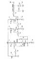
以下、本発明の各実施形態について、図面を参照しながら説明する。図1及び図2は、第1の実施形態に係る3段構成のスイッチトキャパシタ型DC−DCコンバータを示す回路図である。
【0017】
10は電源電圧Vddを提供する電圧源である。C11,C12は直並列切り換えスイッチ61,62,63によって直列又は並列に切り換え可能なコンデンサである。スイッチ61がオン、スイッチ62,63がオフすると、コンデンサC11,C12は互いに直列に接続される。反対にスイッチ61がオフ、スイッチ62,63がオンすると、コンデンサC11,C12は互いに並列に接続される。以下、このような構成のコンデンサC11,C12を直並列コンデンサと呼ぶことにする。
【0018】
11は電源電圧VddとコンデンサC11の一端との間に設けられたスイッチ、21は接地電圧(0V)と各コンデンサC12の一端との間に設けられたスイッチである。
【0019】
C2、C3はそれぞれ2段目、3段目を構成するコンデンサである。12,13は電源電圧Vddと各コンデンサC2,C3の一端との間に設けられたスイッチ、22,23は接地電圧(0V)と各コンデンサC2,C3の他端との間に設けられたスイッチである。
【0020】
上述のスイッチ11〜13、21〜23はコンデンサC11,C12,C2,C3を電源電圧Vddに接続するための充電スイッチ群を構成している。
【0021】
また、30は電源電圧Vddと1段目のコンデンサC12の接地電圧(0V)側の一端の間に設けられたスイッチ、31はコンデンサC11のVdd側の一端と2段目のコンデンサC2の接地電圧(0V)の一端の間に設けられたスイッチ、32はコンデンサC2のVdd側の一端と3段目のコンデンサC3の接地電圧(0V)の一端の間に設けられたスイッチ、33はコンデンサC3のVdd側の一端と出力端子40との間に設けられたスイッチである。Coutは出力容量、50は出力端子40に接続された電流負荷である。
【0022】
上述したスイッチ30〜33は、コンデンサC11,C12,C2,C3を直列に接続して放電を行うための、放電スイッチ群を構成している。
【0023】
なお、上記のスイッチ11〜13,21〜23,30〜33,61〜63は、いずれもMOSトランジスタで構成することにより、DC−DCコンバータをICの中に集積化することができる。
【0024】
次に、図1、図2及び図3を参照しながら、上述した構成のスイッチトキャパシタ型のDC−DCコンバータの第1の動作例を説明する。図3は、スイッチトキャパシタ型のDC−DCコンバータの第1の動作例を説明するタイミング図である。
【0025】
図1に示すように、スイッチ11〜13及びスイッチ21〜23をオンさせ、スイッチ30〜33をオフする。同時に、スイッチ61をオンさせ、スイッチ62,63をオフさせる。
【0026】
すると、コンデンサC11,C12は直列に接続された状態で、電源電圧Vddと接地電圧(0V)の間に接続され、充電がなされる。コンデンサC2,C3は電源電圧Vddと接地電圧(0V)の間に並列に接続され、充電が行われる。
【0027】
これにより、コンデンサC11とC12の接続点の電圧V0は0.5Vddとなり、コンデンサC11の高電圧側の電圧V1はVddとなる。すなわち、各コンデンサC11,C12は0.5Vddに充電される。ただし、各コンデンサC11,C12が有する容量値は等しいとする。もし、各コンデンサC11,C12が有する容量値が異なれば、コンデンサC11とC12の接続点の電圧V0は0.5Vddにはならず、容量比で定まる電圧となる。
【0028】
コンデンサC2,C3の電圧V2,V3はいずれもVddとなる。出力端子40における出力電流をIoutとすると、コンデンサC11,C12の充電電流はIout、コンデンサC2,C3の充電電流は2Ioutである。
【0029】
次に、図2に示すように、スイッチ11〜13及びスイッチ21〜23をオフさせ、スイッチ30〜33をオンする。同時に、スイッチ61をオフさせ、スイッチ62,63をオンさせる。
【0030】
すると、コンデンサC11,C12及びC2,C3は電源電圧Vddと接地電圧(0V)から切り離される。同時に、コンデンサC11,C12は並列接続された状態で、コンデンサC2と相互に直列に接続され、コンデンサC2はさらに3段目のコンデンサC3と相互に直列に接続され、放電が行われる。
【0031】
そして、コンデンサ結合効果により、コンデンサC11の電源電圧Vdd側の一端の電圧V1は1.5Vddとなる。これは、コンデンサC11,C12の接続点の0.5Vddに電圧源10のVddが加算されるからである。そして、同様にコンデンサ結合効果により、電圧V2は2.5Vddに、電圧V3(=Vout)は3.5Vddにそれぞれ昇圧される。
【0032】
出力端子40における出力電流をIoutとすると、電源VddからコンデンサC11,C12に流れる電流はそれぞれIoutである。
【0033】
次に、スイッチトキャパシタ型のDC−DCコンバータの効率について考察する。この図1及び図2に対応するスイッチの切り換え期間が同じであり、スイッチ等により全ての電圧ロスを無視する。すなわち、図3において、時間t1,t2,t3・・・は等しいものとする。
入力電力=(3×2Iout+Iout)/2×Vdd=Iout×3.5Vdd
出力電力=Iout×3.5Vdd
故に、理論効率η=100%である。
【0034】
n段のスイッチトキャパシタ型DC−DCコンバータに拡張すれば、(n+0.5)Vddの出力電圧が得られる。また、1段目のコンデンサC12,C13を常に直列に接続しておけば、(n+1)Vddの出力電圧が得られる。すなわち、1.5Vdd、2Vdd、2.5Vdd、3Vdd、3.5Vdd、・・・というように、0.5Vddステップの出力電圧を発生することが可能であり、しかも理論効率η=100%である。
【0035】
次に、図1、図2及び図4を参照しながら、上述した構成のスイッチトキャパシタ型のDC−DCコンバータの第2の動作例を説明する。図4は、スイッチトキャパシタ型のDC−DCコンバータの第2の動作例を説明するタイミング図である。
【0036】
上述した第1の実施形態では、各スイッチの切り換えを同時に行っているが、スイッチの切り換えのタイミングがずれると電流が逆流して流れてしまう。例えば、コンデンサC11,C12,C2,C3を直列に接続して放電を行うためのスイッチ30〜31をオン状態にしたまま、充電用のスイッチ11〜13,21〜23をオンすると、スイッチ30〜31を通して電流が電源電圧Vddに逆流し、昇圧された電圧が降下してしまう。
【0037】
これは、DC−DCコンバータの効率を悪化させる。同様に、充電用のスイッチ11〜13,21〜23をオフさせるより前に、スイッチ30〜31がオンしてしまうと同様に逆流が生じる。また、スイッチ61とスイッチ62,63との関係でも、同時にこれらのスイッチがオンすると、接地電圧(0V)へ電流の逆流が起こり、同様に、昇圧された電圧が降下してしまい、DC−DCコンバータの効率を悪化させる。
【0038】
そこで、このような電流の逆流を防止するために、スイッチ11〜13,21〜23がスイッチングする時には、他のスイッチ30〜33,スイッチ61〜63は全てオフにしておくことが必要である。
【0039】
以下、図1、図2、図4を参照しながらスイッチの制御ステップについて説明する。まず、全てのスイッチをオフした状態で、充電スイッチ11〜13,21〜23をオンする(図4中の▲1▼)。次に、スイッチ61をオンしてコンデンサC11,C12を直列接続する(図4中の▲2▼)。これにより、コンデンサC11,C12,C2,C3は電源電圧Vddからの電流により充電される。コンデンサC11,C12は直列接続された状態で充電される(図1の状態)。
【0040】
次に、スイッチ61オフする(図4中の▲3▼)。これにより、コンデンサC11,C12は非接続状態となる。その後、充電スイッチ11〜13,21〜23をオフする(図4中の▲4▼)。
【0041】
次に、スイッチ62,63をオンする。これにより、コンデンサC11,C12は並列接続される(図4中の▲5▼)。次に、放電スイッチ30〜33をオンする(図4中の▲6▼)。これにより、コンデンサの結合効果により、コンデンサ結合効果により、コンデンサC11の電源電圧Vdd側の一端の電圧V1は1.5Vddとなる。これは、コンデンサC11,C12の接続点の0.5Vddに電圧源10のVddが加算されるからである。そして、同様にコンデンサ結合効果により、電圧V2は2.5Vddに、電圧V3(=Vout)は3.5Vddにそれぞれ昇圧される(図2の状態)。 次に、放電スイッチ30〜33をオフする(図4中の▲7▼)。次に、スイッチ62,63をオフする(図4中の▲8▼)。以上のステップを繰り返すことにより、電流の逆流を招くことなく、昇圧動作を行うことができる。
【0042】
次に、図5及び図6は、第2の実施形態に係る3段構成のスイッチトキャパシタ型DC−DCコンバータを示す回路図である。このスイッチトキャパシタ型DC−DCコンバータは、2段目に直並列コンデンサC21,C22を有している。スイッチ71,72,73はコンデンサC21,C22を直列又は並列に切り換えるスイッチである。他の構成については、第1の実施形態と同様である。
【0043】
このスイッチトキャパシタ型DC−DCコンバータの動作についても第1の実施形態のものと同様に理解することができる。図4に示すように、スイッチ11〜13及びスイッチ21〜23をオンさせ、スイッチ30〜33をオフする。同時に、スイッチ71をオンさせ、スイッチ72,73をオフさせる。
【0044】
すると、コンデンサC21,C22は直列に接続された状態で、電源電圧Vddと接地電圧(0V)の間に接続され、充電がなされる。1段目のコンデンサC1,3段目のコンデンサC3は電源電圧Vddと接地電圧(0V)の間に並列に接続され、充電がなされる。
【0045】
これにより、コンデンサC21とC22の接続点の電圧V0は0.5Vddとなり、コンデンサC21の高電圧側の電圧V2はVddとなる。すなわち、各コンデンサC21,C22は0.5Vddに充電される。ただし、各コンデンサC21,C22が有する容量値は等しいとする。
【0046】
コンデンサC1,C3の電圧V1,V3はいずれもVddとなる。出力端子40における出力電流をIoutとすると、コンデンサC21,C22の充電電流はIout、コンデンサC2,C3の充電電流は2Ioutである。
【0047】
次に、図6に示すように、スイッチ11〜13及びスイッチ21〜23をオフさせ、スイッチ30〜33をオンする。同時に、スイッチ71をオフさせ、スイッチ72,73をオンさせる。
【0048】
すると、コンデンサC21,C22及びC2,C3は電源電圧Vddと接地電圧(0V)から切り離される。同時に、コンデンサC21,C22は並列接続された状態で、コンデンサC1,C3と相互に直列に接続され、放電が行われる。
【0049】
そして、コンデンサ結合効果により、コンデンサC1の電源電圧Vdd側の一端の電圧V1は2Vddとなる。2段目の電圧V2は2.5Vddとなる。これは、コンデンサC21,C22の接続点の0.5Vddに電圧V1が加算されるからである。そして、同様にコンデンサ結合効果により、電圧V3(=Vout)は3.5Vddにそれぞれ昇圧される。
【0050】
出力端子40における出力電流をIoutとすると、電源VddからコンデンサC1に流れる電流は2Ioutである。これが効率を決める電流である。したがって、本実施形態についても第1の実施形態と同様の条件の下に、
入力電力=(3×2Iout+Iout)/2×Vdd=Iout×3.5Vdd
出力電力=Iout×3.5Vdd
が成立する。故に、理論効率η=100%である。
【0051】
また以上の説明から、直並列コンデンサは何段目に挿入しても同じ結果を得ることができることがわかる。なお、電流の逆流を防止するための動作タイミングについては第1の実施形態で説明したもの(図4参照)と同様である。
【0052】
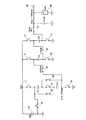
次に、第3の実施形態について図7及び図8を参照しながら説明する。第1及び第2の実施形態はプラスの昇圧電圧を発生するDC−DCコンバータであるが、本実施形態のものは、マイナスの昇圧電圧を発生するDC−DCコンバータである。
【0053】
10は電源電圧Vddを提供する電圧源である。C11,C12はスイッチ81,82,83によって直列又は並列に切り換え可能なコンデンサである。スイッチ81がオン、スイッチ82,83がオフすると、コンデンサC11,C12は互いに直列に接続される。反対にスイッチ81がオフ、スイッチ82,83がオンすると、コンデンサC11,C12は互いに並列に接続される。11は電源電圧VddとコンデンサC11の一端との間に設けられたスイッチ、21は接地電圧(0V)と各コンデンサC12の一端との間に設けられたスイッチである。
【0054】
C2、C3はそれぞれ2段目、3段目を構成するコンデンサである。12,13は電源電圧Vddと各コンデンサC2,C3の一端との間に設けられたスイッチ、22,23は接地電圧(0V)と各コンデンサC2,C3の他端との間に設けられたスイッチである。
【0055】
ここまでは第1の実施形態と同様の構成であるが、以下の構成が異なる。30は接地電圧(0V)と1段目のコンデンサC12の電源電圧(Vdd)側の一端の間に設けられたスイッチ、31はコンデンサC11の接地電圧(0V)側の一端と2段目のコンデンサC2の電源電圧(Vdd)の一端の間に設けられたスイッチ、32はコンデンサC2の接地電圧(0V)側の一端と3段目のコンデンサC3の電源電圧(Vdd)側の一端の間に設けられたスイッチ、33はコンデンサC3の接地電圧(0V)側の一端と出力端子40との間に設けられたスイッチである。
【0056】
なお、Coutは出力容量、50は出力端子40に接続された電流負荷であり、第1の実施形態と同様である。
【0057】
このスイッチトキャパシタ型DC−DCコンバータの動作についても第1及び第2の実施形態のものと同様に理解することができる。図6に示すように、スイッチ11〜13及びスイッチ21〜23をオンさせ、スイッチ30〜33をオフする。同時に、スイッチ81をオンさせ、スイッチ82,83をオフさせる。
【0058】
すると、コンデンサC11,C12は直列に接続された状態で、電源電圧Vddと接地電圧(0V)の間に接続され、充電がなされる。1段目のコンデンサC1,3段目のコンデンサC3は電源電圧Vddと接地電圧(0V)の間に並列に接続され、充電がなされる。
【0059】
これにより、コンデンサC21とC22の接続点の電圧V0は0.5Vddとなり、コンデンサC21の高電圧側の電圧V2はVddとなる。すなわち、各コンデンサC21,C22は0.5Vddに充電される。ただし、各コンデンサC21,C22が有する容量値は等しいとする。ここで、出力端子40における出力電流をIoutとすると、コンデンサC11,C12の充電電流はIout、コンデンサC2,C3の充電電流は2Ioutである。
【0060】
次に、図7に示すように、スイッチ11〜13及びスイッチ21〜23をオフさせ、スイッチ30〜33をオンする。同時に、スイッチ81をオフさせ、スイッチ82,83をオンさせる。
【0061】
すると、コンデンサC11,C12及びC2,C3は電源電圧Vddと接地電圧(0V)から切り離される。同時に、コンデンサC11,C12は並列接続された状態で、コンデンサC2,C3と相互に直列に接続され、放電が行われる。
【0062】
そして、コンデンサ結合効果により、コンデンサC12の接地電圧(0V)側の端子の電圧V1は−0.5Vddとなる。これはコンデンサC11の電源電圧Vdd側の電圧がVddから0Vに変化したことに伴うものである。すると、2段目の電圧V2は−1.5Vddとなる。これは、コンデンサC2の電源電圧Vdd側の電圧がVddから−0.5Vに変化したことに伴うコンデンサ結合効果によるものである。続いて、3段目の電圧V3は−2.5Vddとなる。これは、コンデンサC3の電源電圧Vdd側の電圧がVddから−1.5Vddに変化したことに伴うコンデンサ結合効果によるものである。
【0063】
こうして、出力端子40から出力電圧Vout=−2.5Vddが得られる。
【0064】
本実施形態については、第1の実施形態と同様の条件の下に、
入力電力=(2×2Iout+Iout)/2×Vdd=Iout×2.5Vdd
出力電力=Iout×2.5Vdd
が成立する。故に、理論効率η=100%である。なお、電流の逆流を防止するための動作タイミングについては第1の実施形態で説明したもの(図4参照)と同様である。
【0065】
【発明の効果】
本発明によれば、供給される電源電圧Vddより小さなステップの出力電圧、例えば、1.5Vdd,2.5Vdd、3.5Vdd・・・を発生することが可能なDC−DCコンバータを提供することができる。
特に、DC−DCコンバータを電源回路に適用した場合、電源回路の効率を大幅に向上させることができる。
【図面の簡単な説明】
【図1】本発明の第1の実施形態に係るDC−DCコンバータを示す回路図である。
【図2】本発明の第1の実施形態に係るDC−DCコンバータを示す回路図である。
【図3】本発明の第1の実施形態に係るDC−DCコンバータの第1の動作例を説明するタイミング図である。
【図4】本発明の第1の実施形態に係るDC−DCコンバータの第2の動作例を説明するタイミング図である。
【図5】本発明の第2の実施形態に係るDC−DCコンバータを示す回路図である。
【図6】本発明の第2の実施形態に係るDC−DCコンバータを示す回路図である。
【図7】本発明の第2の実施形態に係るDC−DCコンバータを示す回路図である。
【図8】本発明の第2の実施形態に係るDC−DCコンバータを示す回路図である。
【図9】従来例に係るDC−DCコンバータを示す回路図である。
【図10】従来例に係るDC−DCコンバータを示す回路図である。
【符号の説明】
10 電圧源
11〜13 スイッチ
21〜23 スイッチ
30〜33 スイッチ
40 出力端子
50 電流負荷
61〜63 スイッチ
71〜73 スイッチ
81〜83 スイッチ
C1〜C3 コンデンサ
C11,C12 コンデンサ
C21,C22 コンデンサ
Cout 出力容量[0001]
TECHNICAL FIELD OF THE INVENTION
The present invention relates to a DC-DC converter suitable for use in a power supply circuit and the like, and particularly to a DC-DC converter with high efficiency.
[0002]
[Prior art]
2. Description of the Related Art In recent years, video devices such as a video camera, a digital still camera (DSC), and a DSC phone use a CCD (Charge Coupled Devices) to capture the video. A CCD drive circuit for driving a CCD requires a power supply circuit with a high and a negative high voltage (tens of volts) and a large current (several mA). Currently, this high voltage is generated using a switching regulator.
[0003]
The switching regulator can generate a high voltage with high performance, that is, high power efficiency (output power / input power). However, this circuit has a disadvantage that harmonic noise is generated at the time of current switching, so that the power supply circuit must be used in a shielded manner. Furthermore, there is a disadvantage that miniaturization is difficult because a coil is required as an external component.
[0004]
In order to overcome such disadvantages, a switched capacitor type DC-DC converter has been proposed. This type of DC-DC converter is described, for example, in the Journal of the Institute of Electronics, Information and Communication Engineers (C-2 Vol. J81-C-2 No. 7, pp. 600-612, July 1998).
[0005]
9 and 10 are circuit diagrams of a switched capacitor type DC-DC converter according to a conventional example.
[0006]
[0007]
As shown in FIG. 8, the
[0008]
Next, as shown in FIG. 9, the
[0009]
As described above, the switched capacitor type DC-DC converter can obtain a high voltage of 4 Vdd from the
[0010]
Here, the theoretical efficiency η of the DC-DC converter is defined as output power / input power. The switching periods of the switches corresponding to FIGS. 8 and 9 are the same, and ignoring all voltage losses by switches and the like,
Input power = 4 × 2Iout / 2 × Vdd = Iout × 4Vdd
Output power = Iout × 4Vdd
Therefore, the theoretical efficiency η = 100%.
[0011]
Generally, according to an n-stage switched capacitor type DC-DC converter, an output voltage of (n + 1) Vdd can be obtained.
[0012]
[Problems to be solved by the invention]
However, the conventional switched-capacitor type DC-DC converter can only obtain a boosted voltage in a Vdd step. When a switched-capacitor DC-DC converter is used as a power supply circuit, a regulator performs voltage adjustment by stepping down to set a desired output voltage. However, when the difference between the output voltage (n + 1) Vdd of the DC-DC converter and the desired output voltage is large, there is a disadvantage that the efficiency of the power supply circuit is deteriorated.
[0013]
Accordingly, the present invention provides a DC-DC converter capable of generating an output voltage of a step smaller than Vdd, for example, 1.5 Vdd, 2.5 Vdd, 3.5 Vdd,. The aim is to improve efficiency.
[0014]
[Means for Solving the Problems]
A DC-DC converter according to the present invention includes a series-parallel capacitor including a first switch that switches a first and a second capacitor in series or in parallel, a plurality of capacitors, the series-parallel capacitor, and the plurality of capacitors. A second switch for connecting and charging between the first voltage and the second voltage in parallel, and connecting the series-parallel capacitor and the plurality of capacitors to the first voltage or the second voltage, respectively. And a third switch connected in series between the first and second capacitors for discharging the first and second capacitors of the series-parallel capacitor during charging. And the first and second capacitors are connected in parallel at the time of discharging.
[0015]
At the time of charging, the capacitors are charged in a state of being connected in series, so that each capacitor is charged with a divided voltage (for example, 0.5 Vdd in the case of two capacitors). Then, at the time of discharging, the capacitors are connected in parallel, so that the divided voltage is transmitted to the next-stage capacitor by capacitor coupling. This makes it possible to generate output voltages in steps smaller than Vdd, for example, 1.5 Vdd, 2.5 Vdd, 3.5 Vdd, and so on.
[0016]
BEST MODE FOR CARRYING OUT THE INVENTION
Hereinafter, embodiments of the present invention will be described with reference to the drawings. FIGS. 1 and 2 are circuit diagrams showing a switched-capacitor type DC-DC converter having a three-stage configuration according to the first embodiment.
[0017]
[0018]
[0019]
C2 and C3 are capacitors constituting the second and third stages, respectively.
[0020]
The
[0021]
[0022]
The above-described
[0023]
Each of the
[0024]
Next, a first operation example of the switched capacitor type DC-DC converter having the above-described configuration will be described with reference to FIGS. 1, 2, and 3. FIG. 3 is a timing chart illustrating a first operation example of the switched capacitor type DC-DC converter.
[0025]
As shown in FIG. 1, the
[0026]
Then, the capacitors C11 and C12 are connected in series between the power supply voltage Vdd and the ground voltage (0 V), and are charged. The capacitors C2 and C3 are connected in parallel between the power supply voltage Vdd and the ground voltage (0 V) to perform charging.
[0027]
Thus, the voltage V0 at the connection point between the capacitors C11 and C12 becomes 0.5 Vdd, and the voltage V1 on the high voltage side of the capacitor C11 becomes Vdd. That is, the capacitors C11 and C12 are charged to 0.5 Vdd. However, it is assumed that the capacitance values of the capacitors C11 and C12 are equal. If the capacitance values of the capacitors C11 and C12 are different, the voltage V0 at the connection point between the capacitors C11 and C12 does not become 0.5 Vdd but becomes a voltage determined by the capacitance ratio.
[0028]
The voltages V2 and V3 of the capacitors C2 and C3 both become Vdd. Assuming that the output current at the
[0029]
Next, as shown in FIG. 2, the
[0030]
Then, the capacitors C11 and C12 and C2 and C3 are disconnected from the power supply voltage Vdd and the ground voltage (0 V). At the same time, the capacitors C11 and C12 are connected in series with the capacitor C2 in a state of being connected in parallel, and the capacitor C2 is further connected in series with the capacitor C3 of the third stage to perform discharging.
[0031]
The voltage V1 at one end of the capacitor C11 on the power supply voltage Vdd side becomes 1.5 Vdd due to the capacitor coupling effect. This is because Vdd of the
[0032]
Assuming that the output current at the
[0033]
Next, the efficiency of the switched capacitor type DC-DC converter will be considered. The switching periods of the switches corresponding to FIGS. 1 and 2 are the same, and all the voltage losses are ignored by the switches and the like. That is, in FIG. 3, the times t1, t2, t3,... Are equal.
Input power = (3 × 2Iout + Iout) /2×Vdd=Iout×3.5 Vdd
Output power = Iout × 3.5 Vdd
Therefore, the theoretical efficiency η = 100%.
[0034]
By expanding to an n-stage switched capacitor DC-DC converter, an output voltage of (n + 0.5) Vdd can be obtained. If the first-stage capacitors C12 and C13 are always connected in series, an output voltage of (n + 1) Vdd can be obtained. That is, it is possible to generate an output voltage of 0.5 Vdd steps such as 1.5 Vdd, 2 Vdd, 2.5 Vdd, 3 Vdd, 3.5 Vdd,..., And the theoretical efficiency η = 100%. .
[0035]
Next, a second operation example of the switched capacitor type DC-DC converter having the above-described configuration will be described with reference to FIGS. 1, 2, and 4. FIG. 4 is a timing chart for explaining a second operation example of the switched capacitor type DC-DC converter.
[0036]
In the above-described first embodiment, the switches are switched at the same time. However, if the switching timing of the switches is shifted, a current flows backward. For example, when the
[0037]
This degrades the efficiency of the DC-DC converter. Similarly, if the
[0038]
Therefore, in order to prevent such a reverse current, when the
[0039]
Hereinafter, the control steps of the switch will be described with reference to FIGS. 1, 2, and 4. First, with all the switches off, the charging switches 11 to 13 and 21 to 23 are turned on ((1) in FIG. 4). Next, the
[0040]
Next, the
[0041]
Next, the
[0042]
Next, FIGS. 5 and 6 are circuit diagrams showing a switched-capacitor type DC-DC converter having a three-stage configuration according to the second embodiment. This switched capacitor type DC-DC converter has series-parallel capacitors C21 and C22 at the second stage. The
[0043]
The operation of the switched capacitor type DC-DC converter can be understood in the same manner as that of the first embodiment. As shown in FIG. 4, the
[0044]
Then, while the capacitors C21 and C22 are connected in series, they are connected between the power supply voltage Vdd and the ground voltage (0 V), and charging is performed. The first-stage capacitor C1 and the third-stage capacitor C3 are connected in parallel between the power supply voltage Vdd and the ground voltage (0 V), and are charged.
[0045]
Thus, the voltage V0 at the connection point between the capacitors C21 and C22 becomes 0.5 Vdd, and the voltage V2 on the high voltage side of the capacitor C21 becomes Vdd. That is, the capacitors C21 and C22 are charged to 0.5 Vdd. However, it is assumed that the capacitance values of the capacitors C21 and C22 are equal.
[0046]
Each of the voltages V1 and V3 of the capacitors C1 and C3 becomes Vdd. Assuming that the output current at the
[0047]
Next, as shown in FIG. 6, the
[0048]
Then, the capacitors C21 and C22 and C2 and C3 are disconnected from the power supply voltage Vdd and the ground voltage (0 V). At the same time, the capacitors C21 and C22 are connected in series with the capacitors C1 and C3 in a state of being connected in parallel, and discharging is performed.
[0049]
The voltage V1 at one end of the capacitor C1 on the side of the power supply voltage Vdd becomes 2 Vdd due to the capacitor coupling effect. The second-stage voltage V2 is 2.5 Vdd. This is because the voltage V1 is added to 0.5 Vdd at the connection point between the capacitors C21 and C22. Then, similarly, the voltage V3 (= Vout) is boosted to 3.5 Vdd by the capacitor coupling effect.
[0050]
Assuming that the output current at the
Input power = (3 × 2Iout + Iout) /2×Vdd=Iout×3.5 Vdd
Output power = Iout × 3.5 Vdd
Holds. Therefore, the theoretical efficiency η = 100%.
[0051]
From the above description, it can be seen that the same result can be obtained even if the series-parallel capacitor is inserted at any stage. The operation timing for preventing the backflow of the current is the same as that described in the first embodiment (see FIG. 4).
[0052]
Next, a third embodiment will be described with reference to FIGS. Although the first and second embodiments are DC-DC converters that generate a positive boosted voltage, the present embodiment is a DC-DC converter that generates a negative boosted voltage.
[0053]
[0054]
C2 and C3 are capacitors constituting the second and third stages, respectively.
[0055]
Up to this point, the configuration is the same as that of the first embodiment, but the following configuration is different.
[0056]
Note that Cout is an output capacitance, and 50 is a current load connected to the
[0057]
The operation of the switched capacitor type DC-DC converter can be understood in the same manner as in the first and second embodiments. As shown in FIG. 6, the
[0058]
Then, the capacitors C11 and C12 are connected in series between the power supply voltage Vdd and the ground voltage (0 V), and are charged. The first-stage capacitor C1 and the third-stage capacitor C3 are connected in parallel between the power supply voltage Vdd and the ground voltage (0 V), and are charged.
[0059]
Thus, the voltage V0 at the connection point between the capacitors C21 and C22 becomes 0.5 Vdd, and the voltage V2 on the high voltage side of the capacitor C21 becomes Vdd. That is, the capacitors C21 and C22 are charged to 0.5 Vdd. However, it is assumed that the capacitance values of the capacitors C21 and C22 are equal. Here, assuming that the output current at the
[0060]
Next, as shown in FIG. 7, the
[0061]
Then, the capacitors C11 and C12 and C2 and C3 are disconnected from the power supply voltage Vdd and the ground voltage (0 V). At the same time, the capacitors C11 and C12 are connected in series with the capacitors C2 and C3 in a state of being connected in parallel, and discharging is performed.
[0062]
Due to the capacitor coupling effect, the voltage V1 at the terminal of the capacitor C12 on the ground voltage (0 V) side becomes -0.5 Vdd. This is because the voltage on the power supply voltage Vdd side of the capacitor C11 has changed from Vdd to 0V. Then, the voltage V2 of the second stage becomes -1.5 Vdd. This is due to a capacitor coupling effect caused by a change in the voltage of the capacitor C2 on the power supply voltage Vdd side from Vdd to -0.5V. Subsequently, the voltage V3 at the third stage becomes -2.5 Vdd. This is due to the capacitor coupling effect caused by the change in the voltage of the capacitor C3 on the power supply voltage Vdd side from Vdd to -1.5 Vdd.
[0063]
Thus, an output voltage Vout = −2.5 Vdd is obtained from the
[0064]
In the present embodiment, under the same conditions as in the first embodiment,
Input power = (2 × 2Iout + Iout) /2×Vdd=Iout×2.5Vdd
Output power = Iout × 2.5Vdd
Holds. Therefore, the theoretical efficiency η = 100%. The operation timing for preventing the backflow of the current is the same as that described in the first embodiment (see FIG. 4).
[0065]
【The invention's effect】
According to the present invention, there is provided a DC-DC converter capable of generating an output voltage of a step smaller than a supplied power supply voltage Vdd, for example, 1.5 Vdd, 2.5 Vdd, 3.5 Vdd,. Can be.
In particular, when a DC-DC converter is applied to a power supply circuit, the efficiency of the power supply circuit can be significantly improved.
[Brief description of the drawings]
FIG. 1 is a circuit diagram showing a DC-DC converter according to a first embodiment of the present invention.
FIG. 2 is a circuit diagram showing a DC-DC converter according to the first embodiment of the present invention.
FIG. 3 is a timing chart illustrating a first operation example of the DC-DC converter according to the first embodiment of the present invention.
FIG. 4 is a timing chart illustrating a second operation example of the DC-DC converter according to the first embodiment of the present invention.
FIG. 5 is a circuit diagram showing a DC-DC converter according to a second embodiment of the present invention.
FIG. 6 is a circuit diagram illustrating a DC-DC converter according to a second embodiment of the present invention.
FIG. 7 is a circuit diagram showing a DC-DC converter according to a second embodiment of the present invention.
FIG. 8 is a circuit diagram showing a DC-DC converter according to a second embodiment of the present invention.
FIG. 9 is a circuit diagram showing a DC-DC converter according to a conventional example.
FIG. 10 is a circuit diagram showing a DC-DC converter according to a conventional example.
[Explanation of symbols]
Claims (9)
Translated fromJapanese前記直並列コンデンサと前記複数のコンデンサとをそれぞれ第1の電圧と第2の電圧の間に並列に接続して充電するための第2のスイッチと、
前記直並列コンデンサと前記複数のコンデンサとを前記第1の電圧又は前記第2の電圧と出力端子との間に直列に接続して放電するための第3のスイッチとを備え、
充電時には前記直並列コンデンサの前記第1及び第2のコンデンサを前記第1及び第2の電圧の間に直列に接続し、放電時には前記第1及び第2のコンデンサを並列に接続することを特徴とするDC−DCコンバータ。A series-parallel capacitor having a first switch for switching the first and second capacitors in series or in parallel, a plurality of capacitors,
A second switch for connecting and charging the series-parallel capacitor and the plurality of capacitors in parallel between a first voltage and a second voltage, respectively;
A third switch for discharging the serial-parallel capacitor and the plurality of capacitors connected in series between the first voltage or the second voltage and an output terminal;
When charging, the first and second capacitors of the series-parallel capacitor are connected in series between the first and second voltages, and when discharging, the first and second capacitors are connected in parallel. DC-DC converterto be.
前記直並列コンデンサと前記複数のコンデンサとをそれぞれ高電圧と低電圧の間に並列に接続して充電するための第2のスイッチと、
前記直並列コンデンサと前記複数のコンデンサとを前記高電圧と出力端子との間に直列に接続して放電するための第3のスイッチと、を備え、
充電時には前記直並列コンデンサの前記第1及び第2のコンデンサを前記高電圧と低電圧の間に直列に接続し、放電時には前記第1及び第2のコンデンサを並列に接続し、前記出力端子からプラスの昇圧電圧を発生することを特徴とするDC−DCコンバータ。A series-parallel capacitor having a first switch for switching the first and second capacitors in series or in parallel, a plurality of capacitors,
A second switch for connecting and charging the series-parallel capacitor and the plurality of capacitors in parallel between a high voltage and a low voltage, respectively;
A third switch for connecting and discharging the series-parallel capacitor and the plurality of capacitors in series between the high voltage and an output terminal,
At the time of charging, the first and second capacitors of the series-parallel capacitor are connected in series between the high voltage and the low voltage. At the time of discharging, the first and second capacitors are connected in parallel. A DC-DC converterfor generating a positive boosted voltage .
前記直並列コンデンサと前記複数のコンデンサとをそれぞれ高電圧と低電圧の間に並列に接続して充電するための第2のスイッチと、
前記直並列コンデンサと前記複数のコンデンサとを前記低電圧と出力端子との間に直列に接続して放電するための第3のスイッチと、を備え、
充電時には前記直並列コンデンサの前記第1及び第2のコンデンサを前記第1及び第2の電圧の間に直列に接続し、放電時には前記第1及び第2のコンデンサを並列に接続し、前記前記出力端子からマイナスの昇圧電圧を発生することを特徴とするDC−DCコンバータ。A series-parallel capacitor having a first switch for switching the first and second capacitors in series or in parallel, a plurality of capacitors,
A second switch for connecting and charging the series-parallel capacitor and the plurality of capacitors in parallel between a high voltage and a low voltage, respectively;
A third switch for connecting and discharging the series-parallel capacitor and the plurality of capacitors in series between the low voltage and an output terminal;
When charging, the first and second capacitors of the series-parallel capacitor are connected in series between the first and second voltages, and when discharging, the first and second capacitors are connected in parallel. A DC-DC converterthat generates a negative boosted voltage from an output terminal .
Priority Applications (5)
| Application Number | Priority Date | Filing Date | Title |
|---|---|---|---|
| JP2001294115AJP3557186B2 (en) | 2001-09-26 | 2001-09-26 | DC-DC converter |
| CNB021318859ACN1234202C (en) | 2001-09-26 | 2002-09-05 | DC-DC converter |
| US10/244,624US6834001B2 (en) | 2001-09-26 | 2002-09-16 | Multi-stage switched capacitor DC-DC converter |
| TW091121302ATW578358B (en) | 2001-09-26 | 2002-09-18 | DC-DC converter |
| KR10-2002-0058200AKR100516083B1 (en) | 2001-09-26 | 2002-09-25 | Dc-dc converter |
Applications Claiming Priority (1)
| Application Number | Priority Date | Filing Date | Title |
|---|---|---|---|
| JP2001294115AJP3557186B2 (en) | 2001-09-26 | 2001-09-26 | DC-DC converter |
Publications (2)
| Publication Number | Publication Date |
|---|---|
| JP2003111385A JP2003111385A (en) | 2003-04-11 |
| JP3557186B2true JP3557186B2 (en) | 2004-08-25 |
Family
ID=19115774
Family Applications (1)
| Application Number | Title | Priority Date | Filing Date |
|---|---|---|---|
| JP2001294115AExpired - Fee RelatedJP3557186B2 (en) | 2001-09-26 | 2001-09-26 | DC-DC converter |
Country Status (5)
| Country | Link |
|---|---|
| US (1) | US6834001B2 (en) |
| JP (1) | JP3557186B2 (en) |
| KR (1) | KR100516083B1 (en) |
| CN (1) | CN1234202C (en) |
| TW (1) | TW578358B (en) |
Families Citing this family (584)
| Publication number | Priority date | Publication date | Assignee | Title |
|---|---|---|---|---|
| DE10227375A1 (en)* | 2002-06-20 | 2004-01-15 | Infineon Technologies Ag | Input voltage increasing method for integrated circuit uses charge pump for pre-charging capacitor and for converting its stored charge to be transferred to output capacitor |
| US9060770B2 (en) | 2003-05-20 | 2015-06-23 | Ethicon Endo-Surgery, Inc. | Robotically-driven surgical instrument with E-beam driver |
| US20070084897A1 (en) | 2003-05-20 | 2007-04-19 | Shelton Frederick E Iv | Articulating surgical stapling instrument incorporating a two-piece e-beam firing mechanism |
| US20040264223A1 (en)* | 2003-06-30 | 2004-12-30 | Intel Corporation | Switched capacitor power converter |
| JP2005039936A (en)* | 2003-07-15 | 2005-02-10 | Matsushita Electric Ind Co Ltd | Power supply |
| TWI256761B (en)* | 2003-12-22 | 2006-06-11 | Sunplus Technology Co Ltd | Charging pump circuitry |
| US9533164B2 (en)* | 2004-04-12 | 2017-01-03 | Advanced Neuromodulation Systems, Inc. | Method for providing multiple voltage levels during pulse generation and implantable pulse generating employing the same |
| US7751879B2 (en)* | 2004-04-12 | 2010-07-06 | Advanced Neuromodulation Systems, Inc. | Fractional voltage converter |
| CN100414824C (en)* | 2004-06-19 | 2008-08-27 | 燕山大学 | Magnetic integrated DC/DC conversion step-up transmission ratio expansion circuit |
| US11998198B2 (en) | 2004-07-28 | 2024-06-04 | Cilag Gmbh International | Surgical stapling instrument incorporating a two-piece E-beam firing mechanism |
| US11890012B2 (en) | 2004-07-28 | 2024-02-06 | Cilag Gmbh International | Staple cartridge comprising cartridge body and attached support |
| US9072535B2 (en) | 2011-05-27 | 2015-07-07 | Ethicon Endo-Surgery, Inc. | Surgical stapling instruments with rotatable staple deployment arrangements |
| US8215531B2 (en) | 2004-07-28 | 2012-07-10 | Ethicon Endo-Surgery, Inc. | Surgical stapling instrument having a medical substance dispenser |
| TWI298970B (en) | 2004-07-29 | 2008-07-11 | Sanyo Electric Co | Voltage reduction type dc-dc converter |
| KR101024630B1 (en) | 2004-08-31 | 2011-03-25 | 매그나칩 반도체 유한회사 | Booster circuit |
| JP3964900B2 (en)* | 2004-11-08 | 2007-08-22 | 株式会社東芝 | Voltage supply circuit |
| CN101095276B (en)* | 2005-01-14 | 2011-09-07 | 半导体元件工业有限责任公司 | DC-to-dc converter and method therefor |
| EP1686692A3 (en) | 2005-01-31 | 2006-08-09 | Advanced Neuromodulation Systems, Inc. | Pulse generator having an efficient fractional voltage converter and method of use |
| US20060280655A1 (en)* | 2005-06-08 | 2006-12-14 | California Institute Of Technology | Intravascular diagnostic and therapeutic sampling device |
| JP4175393B2 (en)* | 2005-06-23 | 2008-11-05 | セイコーエプソン株式会社 | Semiconductor device and booster circuit |
| TWI298828B (en)* | 2005-06-29 | 2008-07-11 | Novatek Microelectronics Corp | Charge pump for generating arbitrary voltage level |
| US7669746B2 (en) | 2005-08-31 | 2010-03-02 | Ethicon Endo-Surgery, Inc. | Staple cartridges for forming staples having differing formed staple heights |
| US8800838B2 (en) | 2005-08-31 | 2014-08-12 | Ethicon Endo-Surgery, Inc. | Robotically-controlled cable-based surgical end effectors |
| US7934630B2 (en) | 2005-08-31 | 2011-05-03 | Ethicon Endo-Surgery, Inc. | Staple cartridges for forming staples having differing formed staple heights |
| US7673781B2 (en) | 2005-08-31 | 2010-03-09 | Ethicon Endo-Surgery, Inc. | Surgical stapling device with staple driver that supports multiple wire diameter staples |
| US10159482B2 (en) | 2005-08-31 | 2018-12-25 | Ethicon Llc | Fastener cartridge assembly comprising a fixed anvil and different staple heights |
| US9237891B2 (en) | 2005-08-31 | 2016-01-19 | Ethicon Endo-Surgery, Inc. | Robotically-controlled surgical stapling devices that produce formed staples having different lengths |
| US11246590B2 (en) | 2005-08-31 | 2022-02-15 | Cilag Gmbh International | Staple cartridge including staple drivers having different unfired heights |
| US11484312B2 (en) | 2005-08-31 | 2022-11-01 | Cilag Gmbh International | Staple cartridge comprising a staple driver arrangement |
| JP4699851B2 (en)* | 2005-09-30 | 2011-06-15 | ルネサスエレクトロニクス株式会社 | Booster circuit |
| US20070106317A1 (en) | 2005-11-09 | 2007-05-10 | Shelton Frederick E Iv | Hydraulically and electrically actuated articulation joints for surgical instruments |
| US8161977B2 (en) | 2006-01-31 | 2012-04-24 | Ethicon Endo-Surgery, Inc. | Accessing data stored in a memory of a surgical instrument |
| US11278279B2 (en) | 2006-01-31 | 2022-03-22 | Cilag Gmbh International | Surgical instrument assembly |
| US20120292367A1 (en) | 2006-01-31 | 2012-11-22 | Ethicon Endo-Surgery, Inc. | Robotically-controlled end effector |
| US9861359B2 (en) | 2006-01-31 | 2018-01-09 | Ethicon Llc | Powered surgical instruments with firing system lockout arrangements |
| US20110295295A1 (en) | 2006-01-31 | 2011-12-01 | Ethicon Endo-Surgery, Inc. | Robotically-controlled surgical instrument having recording capabilities |
| US8763879B2 (en) | 2006-01-31 | 2014-07-01 | Ethicon Endo-Surgery, Inc. | Accessing data stored in a memory of surgical instrument |
| US20110024477A1 (en) | 2009-02-06 | 2011-02-03 | Hall Steven G | Driven Surgical Stapler Improvements |
| US8186555B2 (en) | 2006-01-31 | 2012-05-29 | Ethicon Endo-Surgery, Inc. | Motor-driven surgical cutting and fastening instrument with mechanical closure system |
| US7845537B2 (en) | 2006-01-31 | 2010-12-07 | Ethicon Endo-Surgery, Inc. | Surgical instrument having recording capabilities |
| US8820603B2 (en) | 2006-01-31 | 2014-09-02 | Ethicon Endo-Surgery, Inc. | Accessing data stored in a memory of a surgical instrument |
| US8708213B2 (en) | 2006-01-31 | 2014-04-29 | Ethicon Endo-Surgery, Inc. | Surgical instrument having a feedback system |
| US7753904B2 (en) | 2006-01-31 | 2010-07-13 | Ethicon Endo-Surgery, Inc. | Endoscopic surgical instrument with a handle that can articulate with respect to the shaft |
| US11793518B2 (en) | 2006-01-31 | 2023-10-24 | Cilag Gmbh International | Powered surgical instruments with firing system lockout arrangements |
| US11224427B2 (en) | 2006-01-31 | 2022-01-18 | Cilag Gmbh International | Surgical stapling system including a console and retraction assembly |
| US7710184B2 (en)* | 2006-02-08 | 2010-05-04 | Broadcom Corporation | ISI reduction technique |
| US8236010B2 (en) | 2006-03-23 | 2012-08-07 | Ethicon Endo-Surgery, Inc. | Surgical fastener and cutter with mimicking end effector |
| US8992422B2 (en) | 2006-03-23 | 2015-03-31 | Ethicon Endo-Surgery, Inc. | Robotically-controlled endoscopic accessory channel |
| JP4825584B2 (en)* | 2006-05-29 | 2011-11-30 | パナソニック株式会社 | Charge pump circuit |
| US8322455B2 (en) | 2006-06-27 | 2012-12-04 | Ethicon Endo-Surgery, Inc. | Manually driven surgical cutting and fastening instrument |
| US7369419B2 (en)* | 2006-07-05 | 2008-05-06 | Vanguard International Semiconductor Corporation | Voltage converter |
| JP2008042979A (en)* | 2006-08-02 | 2008-02-21 | Rohm Co Ltd | Semiconductor integrated circuit and electronic apparatus equipped with it |
| US10130359B2 (en) | 2006-09-29 | 2018-11-20 | Ethicon Llc | Method for forming a staple |
| US7506791B2 (en) | 2006-09-29 | 2009-03-24 | Ethicon Endo-Surgery, Inc. | Surgical stapling instrument with mechanical mechanism for limiting maximum tissue compression |
| US10568652B2 (en) | 2006-09-29 | 2020-02-25 | Ethicon Llc | Surgical staples having attached drivers of different heights and stapling instruments for deploying the same |
| US11980366B2 (en) | 2006-10-03 | 2024-05-14 | Cilag Gmbh International | Surgical instrument |
| US11291441B2 (en) | 2007-01-10 | 2022-04-05 | Cilag Gmbh International | Surgical instrument with wireless communication between control unit and remote sensor |
| US8652120B2 (en) | 2007-01-10 | 2014-02-18 | Ethicon Endo-Surgery, Inc. | Surgical instrument with wireless communication between control unit and sensor transponders |
| US8632535B2 (en) | 2007-01-10 | 2014-01-21 | Ethicon Endo-Surgery, Inc. | Interlock and surgical instrument including same |
| US8684253B2 (en) | 2007-01-10 | 2014-04-01 | Ethicon Endo-Surgery, Inc. | Surgical instrument with wireless communication between a control unit of a robotic system and remote sensor |
| US8459520B2 (en) | 2007-01-10 | 2013-06-11 | Ethicon Endo-Surgery, Inc. | Surgical instrument with wireless communication between control unit and remote sensor |
| US11039836B2 (en) | 2007-01-11 | 2021-06-22 | Cilag Gmbh International | Staple cartridge for use with a surgical stapling instrument |
| US20080169333A1 (en) | 2007-01-11 | 2008-07-17 | Shelton Frederick E | Surgical stapler end effector with tapered distal end |
| US7673782B2 (en) | 2007-03-15 | 2010-03-09 | Ethicon Endo-Surgery, Inc. | Surgical stapling instrument having a releasable buttress material |
| JP5566568B2 (en)* | 2007-03-27 | 2014-08-06 | ピーエスフォー ルクスコ エスエイアールエル | Power supply voltage generation circuit |
| US8893946B2 (en) | 2007-03-28 | 2014-11-25 | Ethicon Endo-Surgery, Inc. | Laparoscopic tissue thickness and clamp load measuring devices |
| US8931682B2 (en) | 2007-06-04 | 2015-01-13 | Ethicon Endo-Surgery, Inc. | Robotically-controlled shaft based rotary drive systems for surgical instruments |
| US7832408B2 (en) | 2007-06-04 | 2010-11-16 | Ethicon Endo-Surgery, Inc. | Surgical instrument having a directional switching mechanism |
| US7905380B2 (en) | 2007-06-04 | 2011-03-15 | Ethicon Endo-Surgery, Inc. | Surgical instrument having a multiple rate directional switching mechanism |
| US11564682B2 (en) | 2007-06-04 | 2023-01-31 | Cilag Gmbh International | Surgical stapler device |
| US8534528B2 (en) | 2007-06-04 | 2013-09-17 | Ethicon Endo-Surgery, Inc. | Surgical instrument having a multiple rate directional switching mechanism |
| CN100592153C (en)* | 2007-06-08 | 2010-02-24 | 群康科技(深圳)有限公司 | negative voltage generating circuit |
| US8408439B2 (en) | 2007-06-22 | 2013-04-02 | Ethicon Endo-Surgery, Inc. | Surgical stapling instrument with an articulatable end effector |
| US7753245B2 (en) | 2007-06-22 | 2010-07-13 | Ethicon Endo-Surgery, Inc. | Surgical stapling instruments |
| US11849941B2 (en) | 2007-06-29 | 2023-12-26 | Cilag Gmbh International | Staple cartridge having staple cavities extending at a transverse angle relative to a longitudinal cartridge axis |
| US8044705B2 (en) | 2007-08-28 | 2011-10-25 | Sandisk Technologies Inc. | Bottom plate regulation of charge pumps |
| JP5211355B2 (en)* | 2007-11-01 | 2013-06-12 | セミコンダクター・コンポーネンツ・インダストリーズ・リミテッド・ライアビリティ・カンパニー | Power supply circuit and portable device |
| US7586362B2 (en)* | 2007-12-12 | 2009-09-08 | Sandisk Corporation | Low voltage charge pump with regulation |
| US7586363B2 (en)* | 2007-12-12 | 2009-09-08 | Sandisk Corporation | Diode connected regulation of charge pumps |
| US8561870B2 (en) | 2008-02-13 | 2013-10-22 | Ethicon Endo-Surgery, Inc. | Surgical stapling instrument |
| US8758391B2 (en) | 2008-02-14 | 2014-06-24 | Ethicon Endo-Surgery, Inc. | Interchangeable tools for surgical instruments |
| US8636736B2 (en) | 2008-02-14 | 2014-01-28 | Ethicon Endo-Surgery, Inc. | Motorized surgical cutting and fastening instrument |
| US8622274B2 (en)* | 2008-02-14 | 2014-01-07 | Ethicon Endo-Surgery, Inc. | Motorized cutting and fastening instrument having control circuit for optimizing battery usage |
| US8584919B2 (en) | 2008-02-14 | 2013-11-19 | Ethicon Endo-Sugery, Inc. | Surgical stapling apparatus with load-sensitive firing mechanism |
| US8573465B2 (en) | 2008-02-14 | 2013-11-05 | Ethicon Endo-Surgery, Inc. | Robotically-controlled surgical end effector system with rotary actuated closure systems |
| JP5410110B2 (en) | 2008-02-14 | 2014-02-05 | エシコン・エンド−サージェリィ・インコーポレイテッド | Surgical cutting / fixing instrument with RF electrode |
| US7819298B2 (en) | 2008-02-14 | 2010-10-26 | Ethicon Endo-Surgery, Inc. | Surgical stapling apparatus with control features operable with one hand |
| US9179912B2 (en) | 2008-02-14 | 2015-11-10 | Ethicon Endo-Surgery, Inc. | Robotically-controlled motorized surgical cutting and fastening instrument |
| US7866527B2 (en) | 2008-02-14 | 2011-01-11 | Ethicon Endo-Surgery, Inc. | Surgical stapling apparatus with interlockable firing system |
| US11986183B2 (en) | 2008-02-14 | 2024-05-21 | Cilag Gmbh International | Surgical cutting and fastening instrument comprising a plurality of sensors to measure an electrical parameter |
| US8459525B2 (en) | 2008-02-14 | 2013-06-11 | Ethicon Endo-Sugery, Inc. | Motorized surgical cutting and fastening instrument having a magnetic drive train torque limiting device |
| US8752749B2 (en) | 2008-02-14 | 2014-06-17 | Ethicon Endo-Surgery, Inc. | Robotically-controlled disposable motor-driven loading unit |
| US7793812B2 (en) | 2008-02-14 | 2010-09-14 | Ethicon Endo-Surgery, Inc. | Disposable motor-driven loading unit for use with a surgical cutting and stapling apparatus |
| US8657174B2 (en) | 2008-02-14 | 2014-02-25 | Ethicon Endo-Surgery, Inc. | Motorized surgical cutting and fastening instrument having handle based power source |
| US11272927B2 (en) | 2008-02-15 | 2022-03-15 | Cilag Gmbh International | Layer arrangements for surgical staple cartridges |
| US9585657B2 (en) | 2008-02-15 | 2017-03-07 | Ethicon Endo-Surgery, Llc | Actuator for releasing a layer of material from a surgical end effector |
| TWI363266B (en)* | 2008-04-14 | 2012-05-01 | Novatek Microelectronics Corp | Multi-step charge pump and method for producing multi-step charge pumpping |
| US20090302930A1 (en)* | 2008-06-09 | 2009-12-10 | Feng Pan | Charge Pump with Vt Cancellation Through Parallel Structure |
| US7969235B2 (en) | 2008-06-09 | 2011-06-28 | Sandisk Corporation | Self-adaptive multi-stage charge pump |
| US8710907B2 (en) | 2008-06-24 | 2014-04-29 | Sandisk Technologies Inc. | Clock generator circuit for a charge pump |
| US7683700B2 (en) | 2008-06-25 | 2010-03-23 | Sandisk Corporation | Techniques of ripple reduction for charge pumps |
| US7923865B2 (en)* | 2008-06-27 | 2011-04-12 | Medtronic, Inc. | Multi-mode switched capacitor dc-dc voltage converter |
| US8089787B2 (en) | 2008-06-27 | 2012-01-03 | Medtronic, Inc. | Switched capacitor DC-DC voltage converter |
| PL3476312T3 (en) | 2008-09-19 | 2024-03-11 | Ethicon Llc | Surgical stapler with apparatus for adjusting staple height |
| US7954686B2 (en) | 2008-09-19 | 2011-06-07 | Ethicon Endo-Surgery, Inc. | Surgical stapler with apparatus for adjusting staple height |
| US11648005B2 (en) | 2008-09-23 | 2023-05-16 | Cilag Gmbh International | Robotically-controlled motorized surgical instrument with an end effector |
| US9050083B2 (en) | 2008-09-23 | 2015-06-09 | Ethicon Endo-Surgery, Inc. | Motorized surgical instrument |
| US9005230B2 (en) | 2008-09-23 | 2015-04-14 | Ethicon Endo-Surgery, Inc. | Motorized surgical instrument |
| US9386983B2 (en) | 2008-09-23 | 2016-07-12 | Ethicon Endo-Surgery, Llc | Robotically-controlled motorized surgical instrument |
| US8210411B2 (en) | 2008-09-23 | 2012-07-03 | Ethicon Endo-Surgery, Inc. | Motor-driven surgical cutting instrument |
| US8608045B2 (en) | 2008-10-10 | 2013-12-17 | Ethicon Endo-Sugery, Inc. | Powered surgical cutting and stapling apparatus with manually retractable firing system |
| US7795952B2 (en)* | 2008-12-17 | 2010-09-14 | Sandisk Corporation | Regulation of recovery rates in charge pumps |
| US8517239B2 (en) | 2009-02-05 | 2013-08-27 | Ethicon Endo-Surgery, Inc. | Surgical stapling instrument comprising a magnetic element driver |
| US8414577B2 (en) | 2009-02-05 | 2013-04-09 | Ethicon Endo-Surgery, Inc. | Surgical instruments and components for use in sterile environments |
| US8397971B2 (en) | 2009-02-05 | 2013-03-19 | Ethicon Endo-Surgery, Inc. | Sterilizable surgical instrument |
| US8444036B2 (en) | 2009-02-06 | 2013-05-21 | Ethicon Endo-Surgery, Inc. | Motor driven surgical fastener device with mechanisms for adjusting a tissue gap within the end effector |
| US8453907B2 (en) | 2009-02-06 | 2013-06-04 | Ethicon Endo-Surgery, Inc. | Motor driven surgical fastener device with cutting member reversing mechanism |
| RU2525225C2 (en) | 2009-02-06 | 2014-08-10 | Этикон Эндо-Серджери, Инк. | Improvement of drive surgical suturing instrument |
| JP5275096B2 (en)* | 2009-03-18 | 2013-08-28 | 株式会社東芝 | Booster circuit |
| EP2244365A1 (en)* | 2009-04-23 | 2010-10-27 | Mitsubishi Electric R&D Centre Europe B.V. | Method and apparatus for discharging the capacitors of a boost converter composed of plural bridge devices |
| US8456874B2 (en)* | 2009-07-15 | 2013-06-04 | Ramot At Tel Aviv University Ltd. | Partial arbitrary matrix topology (PMAT) and general transposed serial-parallel topology (GTSP) capacitive matrix converters |
| US7973592B2 (en) | 2009-07-21 | 2011-07-05 | Sandisk Corporation | Charge pump with current based regulation |
| US8339183B2 (en) | 2009-07-24 | 2012-12-25 | Sandisk Technologies Inc. | Charge pump with reduced energy consumption through charge sharing and clock boosting suitable for high voltage word line in flash memories |
| US7948301B2 (en)* | 2009-08-28 | 2011-05-24 | Freescale Semiconductor, Inc. | Charge pump with charge feedback and method of operation |
| US8040700B2 (en)* | 2009-11-16 | 2011-10-18 | Freescale Semiconductor, Inc. | Charge pump for use with a synchronous load |
| US7965130B1 (en) | 2009-12-08 | 2011-06-21 | Freescale Semiconductor, Inc. | Low power charge pump and method of operation |
| US8220688B2 (en) | 2009-12-24 | 2012-07-17 | Ethicon Endo-Surgery, Inc. | Motor-driven surgical cutting instrument with electric actuator directional control assembly |
| US8851354B2 (en) | 2009-12-24 | 2014-10-07 | Ethicon Endo-Surgery, Inc. | Surgical cutting instrument that analyzes tissue thickness |
| US8274264B2 (en)* | 2010-02-19 | 2012-09-25 | Exar Corporation | Digital control method for improving heavy-to-light (step down) load transient response of switch mode power supplies |
| US8783543B2 (en) | 2010-07-30 | 2014-07-22 | Ethicon Endo-Surgery, Inc. | Tissue acquisition arrangements and methods for surgical stapling devices |
| US20120078244A1 (en) | 2010-09-24 | 2012-03-29 | Worrell Barry C | Control features for articulating surgical device |
| US9301752B2 (en) | 2010-09-30 | 2016-04-05 | Ethicon Endo-Surgery, Llc | Tissue thickness compensator comprising a plurality of capsules |
| US11298125B2 (en) | 2010-09-30 | 2022-04-12 | Cilag Gmbh International | Tissue stapler having a thickness compensator |
| US9386988B2 (en) | 2010-09-30 | 2016-07-12 | Ethicon End-Surgery, LLC | Retainer assembly including a tissue thickness compensator |
| US8893949B2 (en) | 2010-09-30 | 2014-11-25 | Ethicon Endo-Surgery, Inc. | Surgical stapler with floating anvil |
| US9301753B2 (en) | 2010-09-30 | 2016-04-05 | Ethicon Endo-Surgery, Llc | Expandable tissue thickness compensator |
| US11925354B2 (en) | 2010-09-30 | 2024-03-12 | Cilag Gmbh International | Staple cartridge comprising staples positioned within a compressible portion thereof |
| US9364233B2 (en) | 2010-09-30 | 2016-06-14 | Ethicon Endo-Surgery, Llc | Tissue thickness compensators for circular surgical staplers |
| US9332974B2 (en) | 2010-09-30 | 2016-05-10 | Ethicon Endo-Surgery, Llc | Layered tissue thickness compensator |
| US9220501B2 (en) | 2010-09-30 | 2015-12-29 | Ethicon Endo-Surgery, Inc. | Tissue thickness compensators |
| US9277919B2 (en) | 2010-09-30 | 2016-03-08 | Ethicon Endo-Surgery, Llc | Tissue thickness compensator comprising fibers to produce a resilient load |
| US11812965B2 (en) | 2010-09-30 | 2023-11-14 | Cilag Gmbh International | Layer of material for a surgical end effector |
| US9307989B2 (en) | 2012-03-28 | 2016-04-12 | Ethicon Endo-Surgery, Llc | Tissue stapler having a thickness compensator incorportating a hydrophobic agent |
| US9314246B2 (en) | 2010-09-30 | 2016-04-19 | Ethicon Endo-Surgery, Llc | Tissue stapler having a thickness compensator incorporating an anti-inflammatory agent |
| US9055941B2 (en) | 2011-09-23 | 2015-06-16 | Ethicon Endo-Surgery, Inc. | Staple cartridge including collapsible deck |
| RU2013119928A (en) | 2010-09-30 | 2014-11-10 | Этикон Эндо-Серджери, Инк. | A STAPLING SYSTEM CONTAINING A RETAINING MATRIX AND A LEVELING MATRIX |
| US9788834B2 (en) | 2010-09-30 | 2017-10-17 | Ethicon Llc | Layer comprising deployable attachment members |
| US12213666B2 (en) | 2010-09-30 | 2025-02-04 | Cilag Gmbh International | Tissue thickness compensator comprising layers |
| US10945731B2 (en) | 2010-09-30 | 2021-03-16 | Ethicon Llc | Tissue thickness compensator comprising controlled release and expansion |
| US9232941B2 (en) | 2010-09-30 | 2016-01-12 | Ethicon Endo-Surgery, Inc. | Tissue thickness compensator comprising a reservoir |
| US9629814B2 (en) | 2010-09-30 | 2017-04-25 | Ethicon Endo-Surgery, Llc | Tissue thickness compensator configured to redistribute compressive forces |
| US9351730B2 (en) | 2011-04-29 | 2016-05-31 | Ethicon Endo-Surgery, Llc | Tissue thickness compensator comprising channels |
| US9016542B2 (en) | 2010-09-30 | 2015-04-28 | Ethicon Endo-Surgery, Inc. | Staple cartridge comprising compressible distortion resistant components |
| US8695866B2 (en) | 2010-10-01 | 2014-04-15 | Ethicon Endo-Surgery, Inc. | Surgical instrument having a power control circuit |
| US8339185B2 (en) | 2010-12-20 | 2012-12-25 | Sandisk 3D Llc | Charge pump system that dynamically selects number of active stages |
| US8294509B2 (en) | 2010-12-20 | 2012-10-23 | Sandisk Technologies Inc. | Charge pump systems with reduction in inefficiencies due to charge sharing between capacitances |
| JP5232892B2 (en)* | 2011-04-07 | 2013-07-10 | パナソニック株式会社 | Charge pump circuit |
| AU2012250197B2 (en) | 2011-04-29 | 2017-08-10 | Ethicon Endo-Surgery, Inc. | Staple cartridge comprising staples positioned within a compressible portion thereof |
| US11207064B2 (en) | 2011-05-27 | 2021-12-28 | Cilag Gmbh International | Automated end effector component reloading system for use with a robotic system |
| US8699247B2 (en) | 2011-09-09 | 2014-04-15 | Sandisk Technologies Inc. | Charge pump system dynamically reconfigurable for read and program |
| US8514628B2 (en) | 2011-09-22 | 2013-08-20 | Sandisk Technologies Inc. | Dynamic switching approach to reduce area and power consumption of high voltage charge pumps |
| US8400212B1 (en) | 2011-09-22 | 2013-03-19 | Sandisk Technologies Inc. | High voltage charge pump regulation system with fine step adjustment |
| US9050084B2 (en) | 2011-09-23 | 2015-06-09 | Ethicon Endo-Surgery, Inc. | Staple cartridge including collapsible deck arrangement |
| JP5874350B2 (en)* | 2011-11-28 | 2016-03-02 | オムロン株式会社 | Voltage conversion circuit and electronic device |
| US20130147543A1 (en)* | 2011-12-12 | 2013-06-13 | Futurewei Technologies, Inc. | Apparatus and Method for Fractional Charge Pumps |
| WO2013109719A1 (en) | 2012-01-17 | 2013-07-25 | Massachusetts Institute Of Technology | Stacked switched capacitor energy buffer circuit |
| US9044230B2 (en) | 2012-02-13 | 2015-06-02 | Ethicon Endo-Surgery, Inc. | Surgical cutting and fastening instrument with apparatus for determining cartridge and firing motion status |
| BR112014024098B1 (en) | 2012-03-28 | 2021-05-25 | Ethicon Endo-Surgery, Inc. | staple cartridge |
| MX358135B (en) | 2012-03-28 | 2018-08-06 | Ethicon Endo Surgery Inc | Tissue thickness compensator comprising a plurality of layers. |
| JP6224070B2 (en) | 2012-03-28 | 2017-11-01 | エシコン・エンド−サージェリィ・インコーポレイテッドEthicon Endo−Surgery,Inc. | Retainer assembly including tissue thickness compensator |
| US9198662B2 (en) | 2012-03-28 | 2015-12-01 | Ethicon Endo-Surgery, Inc. | Tissue thickness compensator having improved visibility |
| US9101358B2 (en) | 2012-06-15 | 2015-08-11 | Ethicon Endo-Surgery, Inc. | Articulatable surgical instrument comprising a firing drive |
| US9119657B2 (en) | 2012-06-28 | 2015-09-01 | Ethicon Endo-Surgery, Inc. | Rotary actuatable closure arrangement for surgical end effector |
| BR112014032776B1 (en) | 2012-06-28 | 2021-09-08 | Ethicon Endo-Surgery, Inc | SURGICAL INSTRUMENT SYSTEM AND SURGICAL KIT FOR USE WITH A SURGICAL INSTRUMENT SYSTEM |
| US9561038B2 (en) | 2012-06-28 | 2017-02-07 | Ethicon Endo-Surgery, Llc | Interchangeable clip applier |
| US9282974B2 (en) | 2012-06-28 | 2016-03-15 | Ethicon Endo-Surgery, Llc | Empty clip cartridge lockout |
| US9408606B2 (en) | 2012-06-28 | 2016-08-09 | Ethicon Endo-Surgery, Llc | Robotically powered surgical device with manually-actuatable reversing system |
| US9289256B2 (en) | 2012-06-28 | 2016-03-22 | Ethicon Endo-Surgery, Llc | Surgical end effectors having angled tissue-contacting surfaces |
| US11278284B2 (en) | 2012-06-28 | 2022-03-22 | Cilag Gmbh International | Rotary drive arrangements for surgical instruments |
| US20140001231A1 (en) | 2012-06-28 | 2014-01-02 | Ethicon Endo-Surgery, Inc. | Firing system lockout arrangements for surgical instruments |
| US9125662B2 (en) | 2012-06-28 | 2015-09-08 | Ethicon Endo-Surgery, Inc. | Multi-axis articulating and rotating surgical tools |
| JP6290201B2 (en) | 2012-06-28 | 2018-03-07 | エシコン・エンド−サージェリィ・インコーポレイテッドEthicon Endo−Surgery,Inc. | Lockout for empty clip cartridge |
| US12383267B2 (en) | 2012-06-28 | 2025-08-12 | Cilag Gmbh International | Robotically powered surgical device with manually-actuatable reversing system |
| US9072536B2 (en) | 2012-06-28 | 2015-07-07 | Ethicon Endo-Surgery, Inc. | Differential locking arrangements for rotary powered surgical instruments |
| US9028494B2 (en) | 2012-06-28 | 2015-05-12 | Ethicon Endo-Surgery, Inc. | Interchangeable end effector coupling arrangement |
| US20140005718A1 (en) | 2012-06-28 | 2014-01-02 | Ethicon Endo-Surgery, Inc. | Multi-functional powered surgical device with external dissection features |
| US8747238B2 (en) | 2012-06-28 | 2014-06-10 | Ethicon Endo-Surgery, Inc. | Rotary drive shaft assemblies for surgical instruments with articulatable end effectors |
| US9101385B2 (en) | 2012-06-28 | 2015-08-11 | Ethicon Endo-Surgery, Inc. | Electrode connections for rotary driven surgical tools |
| US8974077B2 (en) | 2012-07-30 | 2015-03-10 | Ultravision Technologies, Llc | Heat sink for LED light source |
| JP5997535B2 (en)* | 2012-08-01 | 2016-09-28 | ローム株式会社 | Charge pump |
| US8710909B2 (en) | 2012-09-14 | 2014-04-29 | Sandisk Technologies Inc. | Circuits for prevention of reverse leakage in Vth-cancellation charge pumps |
| US9386984B2 (en) | 2013-02-08 | 2016-07-12 | Ethicon Endo-Surgery, Llc | Staple cartridge comprising a releasable cover |
| US8836412B2 (en) | 2013-02-11 | 2014-09-16 | Sandisk 3D Llc | Charge pump with a power-controlled clock buffer to reduce power consumption and output voltage ripple |
| US10092292B2 (en) | 2013-02-28 | 2018-10-09 | Ethicon Llc | Staple forming features for surgical stapling instrument |
| JP6028625B2 (en)* | 2013-02-28 | 2016-11-16 | ミツミ電機株式会社 | Charge / discharge control circuit and charge / discharge control method |
| US9468438B2 (en) | 2013-03-01 | 2016-10-18 | Eticon Endo-Surgery, LLC | Sensor straightened end effector during removal through trocar |
| BR112015021082B1 (en) | 2013-03-01 | 2022-05-10 | Ethicon Endo-Surgery, Inc | surgical instrument |
| RU2672520C2 (en) | 2013-03-01 | 2018-11-15 | Этикон Эндо-Серджери, Инк. | Hingedly turnable surgical instruments with conducting ways for signal transfer |
| US9345481B2 (en) | 2013-03-13 | 2016-05-24 | Ethicon Endo-Surgery, Llc | Staple cartridge tissue thickness sensor system |
| US9629629B2 (en) | 2013-03-14 | 2017-04-25 | Ethicon Endo-Surgey, LLC | Control systems for surgical instruments |
| US9808244B2 (en) | 2013-03-14 | 2017-11-07 | Ethicon Llc | Sensor arrangements for absolute positioning system for surgical instruments |
| US9572577B2 (en) | 2013-03-27 | 2017-02-21 | Ethicon Endo-Surgery, Llc | Fastener cartridge comprising a tissue thickness compensator including openings therein |
| US9795384B2 (en) | 2013-03-27 | 2017-10-24 | Ethicon Llc | Fastener cartridge comprising a tissue thickness compensator and a gap setting element |
| US9332984B2 (en) | 2013-03-27 | 2016-05-10 | Ethicon Endo-Surgery, Llc | Fastener cartridge assemblies |
| US9826976B2 (en) | 2013-04-16 | 2017-11-28 | Ethicon Llc | Motor driven surgical instruments with lockable dual drive shafts |
| BR112015026109B1 (en) | 2013-04-16 | 2022-02-22 | Ethicon Endo-Surgery, Inc | surgical instrument |
| US9574644B2 (en) | 2013-05-30 | 2017-02-21 | Ethicon Endo-Surgery, Llc | Power module for use with a surgical instrument |
| US8981835B2 (en) | 2013-06-18 | 2015-03-17 | Sandisk Technologies Inc. | Efficient voltage doubler |
| US9024680B2 (en) | 2013-06-24 | 2015-05-05 | Sandisk Technologies Inc. | Efficiency for charge pumps with low supply voltages |
| US9077238B2 (en) | 2013-06-25 | 2015-07-07 | SanDisk Technologies, Inc. | Capacitive regulation of charge pumps without refresh operation interruption |
| US9007046B2 (en) | 2013-06-27 | 2015-04-14 | Sandisk Technologies Inc. | Efficient high voltage bias regulation circuit |
| US9775609B2 (en) | 2013-08-23 | 2017-10-03 | Ethicon Llc | Tamper proof circuit for surgical instrument battery pack |
| MX369362B (en) | 2013-08-23 | 2019-11-06 | Ethicon Endo Surgery Llc | Firing member retraction devices for powered surgical instruments. |
| US9083231B2 (en) | 2013-09-30 | 2015-07-14 | Sandisk Technologies Inc. | Amplitude modulation for pass gate to improve charge pump efficiency |
| US9154027B2 (en) | 2013-12-09 | 2015-10-06 | Sandisk Technologies Inc. | Dynamic load matching charge pump for reduced current consumption |
| US9724092B2 (en) | 2013-12-23 | 2017-08-08 | Ethicon Llc | Modular surgical instruments |
| US20150173749A1 (en) | 2013-12-23 | 2015-06-25 | Ethicon Endo-Surgery, Inc. | Surgical staples and staple cartridges |
| US9839428B2 (en) | 2013-12-23 | 2017-12-12 | Ethicon Llc | Surgical cutting and stapling instruments with independent jaw control features |
| US20150173756A1 (en) | 2013-12-23 | 2015-06-25 | Ethicon Endo-Surgery, Inc. | Surgical cutting and stapling methods |
| US9195281B2 (en) | 2013-12-31 | 2015-11-24 | Ultravision Technologies, Llc | System and method for a modular multi-panel display |
| US9582237B2 (en) | 2013-12-31 | 2017-02-28 | Ultravision Technologies, Llc | Modular display panels with different pitches |
| US9962161B2 (en) | 2014-02-12 | 2018-05-08 | Ethicon Llc | Deliverable surgical instrument |
| US20140166724A1 (en) | 2014-02-24 | 2014-06-19 | Ethicon Endo-Surgery, Inc. | Staple cartridge including a barbed staple |
| JP6462004B2 (en) | 2014-02-24 | 2019-01-30 | エシコン エルエルシー | Fastening system with launcher lockout |
| US10004497B2 (en) | 2014-03-26 | 2018-06-26 | Ethicon Llc | Interface systems for use with surgical instruments |
| US10013049B2 (en) | 2014-03-26 | 2018-07-03 | Ethicon Llc | Power management through sleep options of segmented circuit and wake up control |
| BR112016021943B1 (en) | 2014-03-26 | 2022-06-14 | Ethicon Endo-Surgery, Llc | SURGICAL INSTRUMENT FOR USE BY AN OPERATOR IN A SURGICAL PROCEDURE |
| US9913642B2 (en) | 2014-03-26 | 2018-03-13 | Ethicon Llc | Surgical instrument comprising a sensor system |
| US20150272580A1 (en) | 2014-03-26 | 2015-10-01 | Ethicon Endo-Surgery, Inc. | Verification of number of battery exchanges/procedure count |
| US12232723B2 (en) | 2014-03-26 | 2025-02-25 | Cilag Gmbh International | Systems and methods for controlling a segmented circuit |
| CN106456176B (en) | 2014-04-16 | 2019-06-28 | 伊西康内外科有限责任公司 | Fastener Cartridge Including Extensions With Different Configurations |
| US20150297225A1 (en) | 2014-04-16 | 2015-10-22 | Ethicon Endo-Surgery, Inc. | Fastener cartridges including extensions having different configurations |
| US10327764B2 (en) | 2014-09-26 | 2019-06-25 | Ethicon Llc | Method for creating a flexible staple line |
| CN106456159B (en) | 2014-04-16 | 2019-03-08 | 伊西康内外科有限责任公司 | Fastener Cartridge Assembly and Nail Retainer Cover Arrangement |
| US10470768B2 (en) | 2014-04-16 | 2019-11-12 | Ethicon Llc | Fastener cartridge including a layer attached thereto |
| BR112016023825B1 (en) | 2014-04-16 | 2022-08-02 | Ethicon Endo-Surgery, Llc | STAPLE CARTRIDGE FOR USE WITH A SURGICAL STAPLER AND STAPLE CARTRIDGE FOR USE WITH A SURGICAL INSTRUMENT |
| US10045781B2 (en) | 2014-06-13 | 2018-08-14 | Ethicon Llc | Closure lockout systems for surgical instruments |
| US9311847B2 (en) | 2014-07-16 | 2016-04-12 | Ultravision Technologies, Llc | Display system having monitoring circuit and methods thereof |
| EP2978119A1 (en)* | 2014-07-23 | 2016-01-27 | Transon Power Units BV | Transformer based switched power converter with switched capacitor auxiliary dc/dc converter |
| US10135242B2 (en) | 2014-09-05 | 2018-11-20 | Ethicon Llc | Smart cartridge wake up operation and data retention |
| BR112017004361B1 (en) | 2014-09-05 | 2023-04-11 | Ethicon Llc | ELECTRONIC SYSTEM FOR A SURGICAL INSTRUMENT |
| US11311294B2 (en) | 2014-09-05 | 2022-04-26 | Cilag Gmbh International | Powered medical device including measurement of closure state of jaws |
| US10105142B2 (en) | 2014-09-18 | 2018-10-23 | Ethicon Llc | Surgical stapler with plurality of cutting elements |
| US11523821B2 (en) | 2014-09-26 | 2022-12-13 | Cilag Gmbh International | Method for creating a flexible staple line |
| CN107427300B (en) | 2014-09-26 | 2020-12-04 | 伊西康有限责任公司 | Surgical suture buttresses and auxiliary materials |
| CN105573392B (en)* | 2014-10-10 | 2018-02-27 | 円星科技股份有限公司 | Voltage generating circuit |
| US10076325B2 (en) | 2014-10-13 | 2018-09-18 | Ethicon Llc | Surgical stapling apparatus comprising a tissue stop |
| US9924944B2 (en) | 2014-10-16 | 2018-03-27 | Ethicon Llc | Staple cartridge comprising an adjunct material |
| US11141153B2 (en) | 2014-10-29 | 2021-10-12 | Cilag Gmbh International | Staple cartridges comprising driver arrangements |
| US10517594B2 (en) | 2014-10-29 | 2019-12-31 | Ethicon Llc | Cartridge assemblies for surgical staplers |
| US9844376B2 (en) | 2014-11-06 | 2017-12-19 | Ethicon Llc | Staple cartridge comprising a releasable adjunct material |
| US10736636B2 (en) | 2014-12-10 | 2020-08-11 | Ethicon Llc | Articulatable surgical instrument system |
| US10117649B2 (en) | 2014-12-18 | 2018-11-06 | Ethicon Llc | Surgical instrument assembly comprising a lockable articulation system |
| US9844375B2 (en) | 2014-12-18 | 2017-12-19 | Ethicon Llc | Drive arrangements for articulatable surgical instruments |
| US9987000B2 (en) | 2014-12-18 | 2018-06-05 | Ethicon Llc | Surgical instrument assembly comprising a flexible articulation system |
| US9943309B2 (en) | 2014-12-18 | 2018-04-17 | Ethicon Llc | Surgical instruments with articulatable end effectors and movable firing beam support arrangements |
| US10085748B2 (en) | 2014-12-18 | 2018-10-02 | Ethicon Llc | Locking arrangements for detachable shaft assemblies with articulatable surgical end effectors |
| US9844374B2 (en) | 2014-12-18 | 2017-12-19 | Ethicon Llc | Surgical instrument systems comprising an articulatable end effector and means for adjusting the firing stroke of a firing member |
| US10188385B2 (en) | 2014-12-18 | 2019-01-29 | Ethicon Llc | Surgical instrument system comprising lockable systems |
| MX389118B (en) | 2014-12-18 | 2025-03-20 | Ethicon Llc | SURGICAL INSTRUMENT WITH AN ANVIL THAT CAN BE SELECTIVELY MOVED ON A DISCRETE, NON-MOBILE AXIS RELATIVE TO A STAPLE CARTRIDGE. |
| US10180463B2 (en) | 2015-02-27 | 2019-01-15 | Ethicon Llc | Surgical apparatus configured to assess whether a performance parameter of the surgical apparatus is within an acceptable performance band |
| US9993258B2 (en) | 2015-02-27 | 2018-06-12 | Ethicon Llc | Adaptable surgical instrument handle |
| US10159483B2 (en) | 2015-02-27 | 2018-12-25 | Ethicon Llc | Surgical apparatus configured to track an end-of-life parameter |
| US11154301B2 (en) | 2015-02-27 | 2021-10-26 | Cilag Gmbh International | Modular stapling assembly |
| US10548504B2 (en) | 2015-03-06 | 2020-02-04 | Ethicon Llc | Overlaid multi sensor radio frequency (RF) electrode system to measure tissue compression |
| US9901342B2 (en) | 2015-03-06 | 2018-02-27 | Ethicon Endo-Surgery, Llc | Signal and power communication system positioned on a rotatable shaft |
| US10245033B2 (en) | 2015-03-06 | 2019-04-02 | Ethicon Llc | Surgical instrument comprising a lockable battery housing |
| JP2020121162A (en) | 2015-03-06 | 2020-08-13 | エシコン エルエルシーEthicon LLC | Time dependent evaluation of sensor data to determine stability element, creep element and viscoelastic element of measurement |
| US9808246B2 (en) | 2015-03-06 | 2017-11-07 | Ethicon Endo-Surgery, Llc | Method of operating a powered surgical instrument |
| US9993248B2 (en) | 2015-03-06 | 2018-06-12 | Ethicon Endo-Surgery, Llc | Smart sensors with local signal processing |
| US9924961B2 (en) | 2015-03-06 | 2018-03-27 | Ethicon Endo-Surgery, Llc | Interactive feedback system for powered surgical instruments |
| US10441279B2 (en) | 2015-03-06 | 2019-10-15 | Ethicon Llc | Multiple level thresholds to modify operation of powered surgical instruments |
| US10617412B2 (en) | 2015-03-06 | 2020-04-14 | Ethicon Llc | System for detecting the mis-insertion of a staple cartridge into a surgical stapler |
| US10045776B2 (en) | 2015-03-06 | 2018-08-14 | Ethicon Llc | Control techniques and sub-processor contained within modular shaft with select control processing from handle |
| US9895148B2 (en) | 2015-03-06 | 2018-02-20 | Ethicon Endo-Surgery, Llc | Monitoring speed control and precision incrementing of motor for powered surgical instruments |
| US10687806B2 (en) | 2015-03-06 | 2020-06-23 | Ethicon Llc | Adaptive tissue compression techniques to adjust closure rates for multiple tissue types |
| US10433844B2 (en) | 2015-03-31 | 2019-10-08 | Ethicon Llc | Surgical instrument with selectively disengageable threaded drive systems |
| US9917507B2 (en) | 2015-05-28 | 2018-03-13 | Sandisk Technologies Llc | Dynamic clock period modulation scheme for variable charge pump load currents |
| US10154841B2 (en) | 2015-06-18 | 2018-12-18 | Ethicon Llc | Surgical stapling instruments with lockout arrangements for preventing firing system actuation when a cartridge is spent or missing |
| JP6526507B2 (en)* | 2015-07-15 | 2019-06-05 | シチズン時計株式会社 | Step-down circuit and step-down charging circuit using the same |
| US9647536B2 (en) | 2015-07-28 | 2017-05-09 | Sandisk Technologies Llc | High voltage generation using low voltage devices |
| US10835249B2 (en) | 2015-08-17 | 2020-11-17 | Ethicon Llc | Implantable layers for a surgical instrument |
| RU2725081C2 (en) | 2015-08-26 | 2020-06-29 | ЭТИКОН ЭлЭлСи | Strips with surgical staples allowing the presence of staples with variable properties and providing simple loading of the cartridge |
| MX2022009705A (en) | 2015-08-26 | 2022-11-07 | Ethicon Llc | Surgical staples comprising hardness variations for improved fastening of tissue. |
| MX2018002392A (en) | 2015-08-26 | 2018-08-01 | Ethicon Llc | Staple cartridge assembly comprising various tissue compression gaps and staple forming gaps. |
| US10980538B2 (en) | 2015-08-26 | 2021-04-20 | Ethicon Llc | Surgical stapling configurations for curved and circular stapling instruments |
| MX2022006189A (en) | 2015-09-02 | 2022-06-16 | Ethicon Llc | Surgical staple configurations with camming surfaces located between portions supporting surgical staples. |
| US10238390B2 (en) | 2015-09-02 | 2019-03-26 | Ethicon Llc | Surgical staple cartridges with driver arrangements for establishing herringbone staple patterns |
| US9520776B1 (en) | 2015-09-18 | 2016-12-13 | Sandisk Technologies Llc | Selective body bias for charge pump transfer switches |
| US10076326B2 (en) | 2015-09-23 | 2018-09-18 | Ethicon Llc | Surgical stapler having current mirror-based motor control |
| US10105139B2 (en) | 2015-09-23 | 2018-10-23 | Ethicon Llc | Surgical stapler having downstream current-based motor control |
| US10085751B2 (en) | 2015-09-23 | 2018-10-02 | Ethicon Llc | Surgical stapler having temperature-based motor control |
| US10363036B2 (en) | 2015-09-23 | 2019-07-30 | Ethicon Llc | Surgical stapler having force-based motor control |
| US10327769B2 (en) | 2015-09-23 | 2019-06-25 | Ethicon Llc | Surgical stapler having motor control based on a drive system component |
| US10238386B2 (en) | 2015-09-23 | 2019-03-26 | Ethicon Llc | Surgical stapler having motor control based on an electrical parameter related to a motor current |
| US10299878B2 (en) | 2015-09-25 | 2019-05-28 | Ethicon Llc | Implantable adjunct systems for determining adjunct skew |
| US10433846B2 (en) | 2015-09-30 | 2019-10-08 | Ethicon Llc | Compressible adjunct with crossing spacer fibers |
| US11890015B2 (en) | 2015-09-30 | 2024-02-06 | Cilag Gmbh International | Compressible adjunct with crossing spacer fibers |
| US10478188B2 (en) | 2015-09-30 | 2019-11-19 | Ethicon Llc | Implantable layer comprising a constricted configuration |
| US10980539B2 (en) | 2015-09-30 | 2021-04-20 | Ethicon Llc | Implantable adjunct comprising bonded layers |
| US10265068B2 (en) | 2015-12-30 | 2019-04-23 | Ethicon Llc | Surgical instruments with separable motors and motor control circuits |
| US10368865B2 (en) | 2015-12-30 | 2019-08-06 | Ethicon Llc | Mechanisms for compensating for drivetrain failure in powered surgical instruments |
| US10292704B2 (en) | 2015-12-30 | 2019-05-21 | Ethicon Llc | Mechanisms for compensating for battery pack failure in powered surgical instruments |
| US10413291B2 (en) | 2016-02-09 | 2019-09-17 | Ethicon Llc | Surgical instrument articulation mechanism with slotted secondary constraint |
| US11213293B2 (en) | 2016-02-09 | 2022-01-04 | Cilag Gmbh International | Articulatable surgical instruments with single articulation link arrangements |
| BR112018016098B1 (en) | 2016-02-09 | 2023-02-23 | Ethicon Llc | SURGICAL INSTRUMENT |
| US10448948B2 (en) | 2016-02-12 | 2019-10-22 | Ethicon Llc | Mechanisms for compensating for drivetrain failure in powered surgical instruments |
| US10258331B2 (en) | 2016-02-12 | 2019-04-16 | Ethicon Llc | Mechanisms for compensating for drivetrain failure in powered surgical instruments |
| US11224426B2 (en) | 2016-02-12 | 2022-01-18 | Cilag Gmbh International | Mechanisms for compensating for drivetrain failure in powered surgical instruments |
| US20170279349A1 (en)* | 2016-03-24 | 2017-09-28 | Linear Technology Corporation | High efficiency charge pump with auxiliary input operative to optimize conversion ratio |
| US10413297B2 (en) | 2016-04-01 | 2019-09-17 | Ethicon Llc | Surgical stapling system configured to apply annular rows of staples having different heights |
| US10617413B2 (en) | 2016-04-01 | 2020-04-14 | Ethicon Llc | Closure system arrangements for surgical cutting and stapling devices with separate and distinct firing shafts |
| US10405859B2 (en) | 2016-04-15 | 2019-09-10 | Ethicon Llc | Surgical instrument with adjustable stop/start control during a firing motion |
| US10492783B2 (en) | 2016-04-15 | 2019-12-03 | Ethicon, Llc | Surgical instrument with improved stop/start control during a firing motion |
| US10335145B2 (en) | 2016-04-15 | 2019-07-02 | Ethicon Llc | Modular surgical instrument with configurable operating mode |
| US10828028B2 (en) | 2016-04-15 | 2020-11-10 | Ethicon Llc | Surgical instrument with multiple program responses during a firing motion |
| US10357247B2 (en) | 2016-04-15 | 2019-07-23 | Ethicon Llc | Surgical instrument with multiple program responses during a firing motion |
| US11607239B2 (en) | 2016-04-15 | 2023-03-21 | Cilag Gmbh International | Systems and methods for controlling a surgical stapling and cutting instrument |
| US11179150B2 (en) | 2016-04-15 | 2021-11-23 | Cilag Gmbh International | Systems and methods for controlling a surgical stapling and cutting instrument |
| US10426467B2 (en) | 2016-04-15 | 2019-10-01 | Ethicon Llc | Surgical instrument with detection sensors |
| US10456137B2 (en) | 2016-04-15 | 2019-10-29 | Ethicon Llc | Staple formation detection mechanisms |
| US11317917B2 (en) | 2016-04-18 | 2022-05-03 | Cilag Gmbh International | Surgical stapling system comprising a lockable firing assembly |
| US20170296173A1 (en) | 2016-04-18 | 2017-10-19 | Ethicon Endo-Surgery, Llc | Method for operating a surgical instrument |
| US10363037B2 (en) | 2016-04-18 | 2019-07-30 | Ethicon Llc | Surgical instrument system comprising a magnetic lockout |
| US10893863B2 (en) | 2016-06-24 | 2021-01-19 | Ethicon Llc | Staple cartridge comprising offset longitudinal staple rows |
| USD847989S1 (en) | 2016-06-24 | 2019-05-07 | Ethicon Llc | Surgical fastener cartridge |
| USD850617S1 (en) | 2016-06-24 | 2019-06-04 | Ethicon Llc | Surgical fastener cartridge |
| JP6980705B2 (en) | 2016-06-24 | 2021-12-15 | エシコン エルエルシーEthicon LLC | Stapling system for use with wire staples and punched staples |
| USD826405S1 (en) | 2016-06-24 | 2018-08-21 | Ethicon Llc | Surgical fastener |
| JP6957532B2 (en) | 2016-06-24 | 2021-11-02 | エシコン エルエルシーEthicon LLC | Staple cartridges including wire staples and punched staples |
| CN106130372B (en)* | 2016-07-21 | 2018-07-03 | 唐山东唐电气股份有限公司 | AC variable step-up power supply |
| US10500000B2 (en) | 2016-08-16 | 2019-12-10 | Ethicon Llc | Surgical tool with manual control of end effector jaws |
| US20180168615A1 (en) | 2016-12-21 | 2018-06-21 | Ethicon Endo-Surgery, Llc | Method of deforming staples from two different types of staple cartridges with the same surgical stapling instrument |
| US11134942B2 (en) | 2016-12-21 | 2021-10-05 | Cilag Gmbh International | Surgical stapling instruments and staple-forming anvils |
| US10813638B2 (en) | 2016-12-21 | 2020-10-27 | Ethicon Llc | Surgical end effectors with expandable tissue stop arrangements |
| JP7010957B2 (en) | 2016-12-21 | 2022-01-26 | エシコン エルエルシー | Shaft assembly with lockout |
| US10980536B2 (en) | 2016-12-21 | 2021-04-20 | Ethicon Llc | No-cartridge and spent cartridge lockout arrangements for surgical staplers |
| JP7010956B2 (en) | 2016-12-21 | 2022-01-26 | エシコン エルエルシー | How to staple tissue |
| US10582928B2 (en) | 2016-12-21 | 2020-03-10 | Ethicon Llc | Articulation lock arrangements for locking an end effector in an articulated position in response to actuation of a jaw closure system |
| US10758229B2 (en) | 2016-12-21 | 2020-09-01 | Ethicon Llc | Surgical instrument comprising improved jaw control |
| US10687810B2 (en) | 2016-12-21 | 2020-06-23 | Ethicon Llc | Stepped staple cartridge with tissue retention and gap setting features |
| US10973516B2 (en) | 2016-12-21 | 2021-04-13 | Ethicon Llc | Surgical end effectors and adaptable firing members therefor |
| US20180168648A1 (en) | 2016-12-21 | 2018-06-21 | Ethicon Endo-Surgery, Llc | Durability features for end effectors and firing assemblies of surgical stapling instruments |
| US20180168625A1 (en) | 2016-12-21 | 2018-06-21 | Ethicon Endo-Surgery, Llc | Surgical stapling instruments with smart staple cartridges |
| US11090048B2 (en) | 2016-12-21 | 2021-08-17 | Cilag Gmbh International | Method for resetting a fuse of a surgical instrument shaft |
| US11684367B2 (en) | 2016-12-21 | 2023-06-27 | Cilag Gmbh International | Stepped assembly having and end-of-life indicator |
| US10568625B2 (en) | 2016-12-21 | 2020-02-25 | Ethicon Llc | Staple cartridges and arrangements of staples and staple cavities therein |
| MX2019007295A (en) | 2016-12-21 | 2019-10-15 | Ethicon Llc | Surgical instrument system comprising an end effector lockout and a firing assembly lockout. |
| US10945727B2 (en) | 2016-12-21 | 2021-03-16 | Ethicon Llc | Staple cartridge with deformable driver retention features |
| US10993715B2 (en) | 2016-12-21 | 2021-05-04 | Ethicon Llc | Staple cartridge comprising staples with different clamping breadths |
| US10898186B2 (en) | 2016-12-21 | 2021-01-26 | Ethicon Llc | Staple forming pocket arrangements comprising primary sidewalls and pocket sidewalls |
| US10485543B2 (en) | 2016-12-21 | 2019-11-26 | Ethicon Llc | Anvil having a knife slot width |
| JP2020501815A (en) | 2016-12-21 | 2020-01-23 | エシコン エルエルシーEthicon LLC | Surgical stapling system |
| US10426471B2 (en) | 2016-12-21 | 2019-10-01 | Ethicon Llc | Surgical instrument with multiple failure response modes |
| US10695055B2 (en) | 2016-12-21 | 2020-06-30 | Ethicon Llc | Firing assembly comprising a lockout |
| US10542982B2 (en) | 2016-12-21 | 2020-01-28 | Ethicon Llc | Shaft assembly comprising first and second articulation lockouts |
| US11419606B2 (en) | 2016-12-21 | 2022-08-23 | Cilag Gmbh International | Shaft assembly comprising a clutch configured to adapt the output of a rotary firing member to two different systems |
| CN110087565A (en) | 2016-12-21 | 2019-08-02 | 爱惜康有限责任公司 | Surgical stapling system |
| JP6983893B2 (en) | 2016-12-21 | 2021-12-17 | エシコン エルエルシーEthicon LLC | Lockout configuration for surgical end effectors and replaceable tool assemblies |
| EP3610552B1 (en)* | 2017-06-12 | 2023-11-29 | Gbatteries Energy Canada Inc. | Battery charging through multi-stage voltage conversion |
| US11653914B2 (en) | 2017-06-20 | 2023-05-23 | Cilag Gmbh International | Systems and methods for controlling motor velocity of a surgical stapling and cutting instrument according to articulation angle of end effector |
| US10390841B2 (en) | 2017-06-20 | 2019-08-27 | Ethicon Llc | Control of motor velocity of a surgical stapling and cutting instrument based on angle of articulation |
| USD879809S1 (en) | 2017-06-20 | 2020-03-31 | Ethicon Llc | Display panel with changeable graphical user interface |
| US10368864B2 (en) | 2017-06-20 | 2019-08-06 | Ethicon Llc | Systems and methods for controlling displaying motor velocity for a surgical instrument |
| US11517325B2 (en) | 2017-06-20 | 2022-12-06 | Cilag Gmbh International | Closed loop feedback control of motor velocity of a surgical stapling and cutting instrument based on measured displacement distance traveled over a specified time interval |
| US10813639B2 (en) | 2017-06-20 | 2020-10-27 | Ethicon Llc | Closed loop feedback control of motor velocity of a surgical stapling and cutting instrument based on system conditions |
| US11382638B2 (en) | 2017-06-20 | 2022-07-12 | Cilag Gmbh International | Closed loop feedback control of motor velocity of a surgical stapling and cutting instrument based on measured time over a specified displacement distance |
| US10624633B2 (en) | 2017-06-20 | 2020-04-21 | Ethicon Llc | Systems and methods for controlling motor velocity of a surgical stapling and cutting instrument |
| USD879808S1 (en) | 2017-06-20 | 2020-03-31 | Ethicon Llc | Display panel with graphical user interface |
| US10307170B2 (en) | 2017-06-20 | 2019-06-04 | Ethicon Llc | Method for closed loop control of motor velocity of a surgical stapling and cutting instrument |
| US11090046B2 (en) | 2017-06-20 | 2021-08-17 | Cilag Gmbh International | Systems and methods for controlling displacement member motion of a surgical stapling and cutting instrument |
| US10881399B2 (en) | 2017-06-20 | 2021-01-05 | Ethicon Llc | Techniques for adaptive control of motor velocity of a surgical stapling and cutting instrument |
| US11071554B2 (en) | 2017-06-20 | 2021-07-27 | Cilag Gmbh International | Closed loop feedback control of motor velocity of a surgical stapling and cutting instrument based on magnitude of velocity error measurements |
| US10888321B2 (en) | 2017-06-20 | 2021-01-12 | Ethicon Llc | Systems and methods for controlling velocity of a displacement member of a surgical stapling and cutting instrument |
| USD890784S1 (en) | 2017-06-20 | 2020-07-21 | Ethicon Llc | Display panel with changeable graphical user interface |
| US10327767B2 (en) | 2017-06-20 | 2019-06-25 | Ethicon Llc | Control of motor velocity of a surgical stapling and cutting instrument based on angle of articulation |
| US10980537B2 (en) | 2017-06-20 | 2021-04-20 | Ethicon Llc | Closed loop feedback control of motor velocity of a surgical stapling and cutting instrument based on measured time over a specified number of shaft rotations |
| US10646220B2 (en) | 2017-06-20 | 2020-05-12 | Ethicon Llc | Systems and methods for controlling displacement member velocity for a surgical instrument |
| US10881396B2 (en) | 2017-06-20 | 2021-01-05 | Ethicon Llc | Surgical instrument with variable duration trigger arrangement |
| US10779820B2 (en) | 2017-06-20 | 2020-09-22 | Ethicon Llc | Systems and methods for controlling motor speed according to user input for a surgical instrument |
| US11266405B2 (en) | 2017-06-27 | 2022-03-08 | Cilag Gmbh International | Surgical anvil manufacturing methods |
| US10856869B2 (en) | 2017-06-27 | 2020-12-08 | Ethicon Llc | Surgical anvil arrangements |
| US11090049B2 (en) | 2017-06-27 | 2021-08-17 | Cilag Gmbh International | Staple forming pocket arrangements |
| US11324503B2 (en) | 2017-06-27 | 2022-05-10 | Cilag Gmbh International | Surgical firing member arrangements |
| US10772629B2 (en) | 2017-06-27 | 2020-09-15 | Ethicon Llc | Surgical anvil arrangements |
| US10993716B2 (en) | 2017-06-27 | 2021-05-04 | Ethicon Llc | Surgical anvil arrangements |
| US10765427B2 (en) | 2017-06-28 | 2020-09-08 | Ethicon Llc | Method for articulating a surgical instrument |
| US10211586B2 (en) | 2017-06-28 | 2019-02-19 | Ethicon Llc | Surgical shaft assemblies with watertight housings |
| USD851762S1 (en) | 2017-06-28 | 2019-06-18 | Ethicon Llc | Anvil |
| US11484310B2 (en) | 2017-06-28 | 2022-11-01 | Cilag Gmbh International | Surgical instrument comprising a shaft including a closure tube profile |
| US10758232B2 (en) | 2017-06-28 | 2020-09-01 | Ethicon Llc | Surgical instrument with positive jaw opening features |
| US11564686B2 (en) | 2017-06-28 | 2023-01-31 | Cilag Gmbh International | Surgical shaft assemblies with flexible interfaces |
| USD854151S1 (en) | 2017-06-28 | 2019-07-16 | Ethicon Llc | Surgical instrument shaft |
| USD906355S1 (en) | 2017-06-28 | 2020-12-29 | Ethicon Llc | Display screen or portion thereof with a graphical user interface for a surgical instrument |
| US11259805B2 (en) | 2017-06-28 | 2022-03-01 | Cilag Gmbh International | Surgical instrument comprising firing member supports |
| EP3420947B1 (en) | 2017-06-28 | 2022-05-25 | Cilag GmbH International | Surgical instrument comprising selectively actuatable rotatable couplers |
| US11246592B2 (en) | 2017-06-28 | 2022-02-15 | Cilag Gmbh International | Surgical instrument comprising an articulation system lockable to a frame |
| USD869655S1 (en) | 2017-06-28 | 2019-12-10 | Ethicon Llc | Surgical fastener cartridge |
| US10903685B2 (en) | 2017-06-28 | 2021-01-26 | Ethicon Llc | Surgical shaft assemblies with slip ring assemblies forming capacitive channels |
| US10716614B2 (en) | 2017-06-28 | 2020-07-21 | Ethicon Llc | Surgical shaft assemblies with slip ring assemblies with increased contact pressure |
| US10898183B2 (en) | 2017-06-29 | 2021-01-26 | Ethicon Llc | Robotic surgical instrument with closed loop feedback techniques for advancement of closure member during firing |
| US10398434B2 (en) | 2017-06-29 | 2019-09-03 | Ethicon Llc | Closed loop velocity control of closure member for robotic surgical instrument |
| US10258418B2 (en) | 2017-06-29 | 2019-04-16 | Ethicon Llc | System for controlling articulation forces |
| US11007022B2 (en) | 2017-06-29 | 2021-05-18 | Ethicon Llc | Closed loop velocity control techniques based on sensed tissue parameters for robotic surgical instrument |
| US10932772B2 (en) | 2017-06-29 | 2021-03-02 | Ethicon Llc | Methods for closed loop velocity control for robotic surgical instrument |
| US11944300B2 (en) | 2017-08-03 | 2024-04-02 | Cilag Gmbh International | Method for operating a surgical system bailout |
| US11974742B2 (en) | 2017-08-03 | 2024-05-07 | Cilag Gmbh International | Surgical system comprising an articulation bailout |
| US11304695B2 (en) | 2017-08-03 | 2022-04-19 | Cilag Gmbh International | Surgical system shaft interconnection |
| US11471155B2 (en) | 2017-08-03 | 2022-10-18 | Cilag Gmbh International | Surgical system bailout |
| CN107422779B (en)* | 2017-08-21 | 2019-02-22 | 南京矽力杰半导体技术有限公司 | Voltage regulator |
| USD907648S1 (en) | 2017-09-29 | 2021-01-12 | Ethicon Llc | Display screen or portion thereof with animated graphical user interface |
| US10765429B2 (en) | 2017-09-29 | 2020-09-08 | Ethicon Llc | Systems and methods for providing alerts according to the operational state of a surgical instrument |
| US10743872B2 (en) | 2017-09-29 | 2020-08-18 | Ethicon Llc | System and methods for controlling a display of a surgical instrument |
| US11399829B2 (en) | 2017-09-29 | 2022-08-02 | Cilag Gmbh International | Systems and methods of initiating a power shutdown mode for a surgical instrument |
| USD917500S1 (en) | 2017-09-29 | 2021-04-27 | Ethicon Llc | Display screen or portion thereof with graphical user interface |
| US10729501B2 (en) | 2017-09-29 | 2020-08-04 | Ethicon Llc | Systems and methods for language selection of a surgical instrument |
| US10796471B2 (en) | 2017-09-29 | 2020-10-06 | Ethicon Llc | Systems and methods of displaying a knife position for a surgical instrument |
| USD907647S1 (en) | 2017-09-29 | 2021-01-12 | Ethicon Llc | Display screen or portion thereof with animated graphical user interface |
| CN107834844B (en)* | 2017-10-19 | 2020-04-03 | 华为技术有限公司 | A switched capacitor conversion circuit, charging control system and control method |
| US11134944B2 (en) | 2017-10-30 | 2021-10-05 | Cilag Gmbh International | Surgical stapler knife motion controls |
| US11090075B2 (en) | 2017-10-30 | 2021-08-17 | Cilag Gmbh International | Articulation features for surgical end effector |
| US10842490B2 (en) | 2017-10-31 | 2020-11-24 | Ethicon Llc | Cartridge body design with force reduction based on firing completion |
| US10779903B2 (en) | 2017-10-31 | 2020-09-22 | Ethicon Llc | Positive shaft rotation lock activated by jaw closure |
| US11006955B2 (en) | 2017-12-15 | 2021-05-18 | Ethicon Llc | End effectors with positive jaw opening features for use with adapters for electromechanical surgical instruments |
| US10869666B2 (en) | 2017-12-15 | 2020-12-22 | Ethicon Llc | Adapters with control systems for controlling multiple motors of an electromechanical surgical instrument |
| US11197670B2 (en) | 2017-12-15 | 2021-12-14 | Cilag Gmbh International | Surgical end effectors with pivotal jaws configured to touch at their respective distal ends when fully closed |
| US10743874B2 (en) | 2017-12-15 | 2020-08-18 | Ethicon Llc | Sealed adapters for use with electromechanical surgical instruments |
| US10828033B2 (en) | 2017-12-15 | 2020-11-10 | Ethicon Llc | Handheld electromechanical surgical instruments with improved motor control arrangements for positioning components of an adapter coupled thereto |
| US10779826B2 (en) | 2017-12-15 | 2020-09-22 | Ethicon Llc | Methods of operating surgical end effectors |
| US10966718B2 (en) | 2017-12-15 | 2021-04-06 | Ethicon Llc | Dynamic clamping assemblies with improved wear characteristics for use in connection with electromechanical surgical instruments |
| US11033267B2 (en) | 2017-12-15 | 2021-06-15 | Ethicon Llc | Systems and methods of controlling a clamping member firing rate of a surgical instrument |
| US11071543B2 (en) | 2017-12-15 | 2021-07-27 | Cilag Gmbh International | Surgical end effectors with clamping assemblies configured to increase jaw aperture ranges |
| US10743875B2 (en) | 2017-12-15 | 2020-08-18 | Ethicon Llc | Surgical end effectors with jaw stiffener arrangements configured to permit monitoring of firing member |
| US10779825B2 (en) | 2017-12-15 | 2020-09-22 | Ethicon Llc | Adapters with end effector position sensing and control arrangements for use in connection with electromechanical surgical instruments |
| US10687813B2 (en) | 2017-12-15 | 2020-06-23 | Ethicon Llc | Adapters with firing stroke sensing arrangements for use in connection with electromechanical surgical instruments |
| USD910847S1 (en) | 2017-12-19 | 2021-02-16 | Ethicon Llc | Surgical instrument assembly |
| US10835330B2 (en) | 2017-12-19 | 2020-11-17 | Ethicon Llc | Method for determining the position of a rotatable jaw of a surgical instrument attachment assembly |
| US10716565B2 (en) | 2017-12-19 | 2020-07-21 | Ethicon Llc | Surgical instruments with dual articulation drivers |
| US11020112B2 (en) | 2017-12-19 | 2021-06-01 | Ethicon Llc | Surgical tools configured for interchangeable use with different controller interfaces |
| US11045270B2 (en) | 2017-12-19 | 2021-06-29 | Cilag Gmbh International | Robotic attachment comprising exterior drive actuator |
| US10729509B2 (en) | 2017-12-19 | 2020-08-04 | Ethicon Llc | Surgical instrument comprising closure and firing locking mechanism |
| US11311290B2 (en) | 2017-12-21 | 2022-04-26 | Cilag Gmbh International | Surgical instrument comprising an end effector dampener |
| US11076853B2 (en) | 2017-12-21 | 2021-08-03 | Cilag Gmbh International | Systems and methods of displaying a knife position during transection for a surgical instrument |
| US11179151B2 (en) | 2017-12-21 | 2021-11-23 | Cilag Gmbh International | Surgical instrument comprising a display |
| US12336705B2 (en) | 2017-12-21 | 2025-06-24 | Cilag Gmbh International | Continuous use self-propelled stapling instrument |
| US11129680B2 (en) | 2017-12-21 | 2021-09-28 | Cilag Gmbh International | Surgical instrument comprising a projector |
| US11324501B2 (en) | 2018-08-20 | 2022-05-10 | Cilag Gmbh International | Surgical stapling devices with improved closure members |
| US11291440B2 (en) | 2018-08-20 | 2022-04-05 | Cilag Gmbh International | Method for operating a powered articulatable surgical instrument |
| US11045192B2 (en) | 2018-08-20 | 2021-06-29 | Cilag Gmbh International | Fabricating techniques for surgical stapler anvils |
| US10856870B2 (en) | 2018-08-20 | 2020-12-08 | Ethicon Llc | Switching arrangements for motor powered articulatable surgical instruments |
| US11039834B2 (en) | 2018-08-20 | 2021-06-22 | Cilag Gmbh International | Surgical stapler anvils with staple directing protrusions and tissue stability features |
| US11253256B2 (en) | 2018-08-20 | 2022-02-22 | Cilag Gmbh International | Articulatable motor powered surgical instruments with dedicated articulation motor arrangements |
| US10912559B2 (en) | 2018-08-20 | 2021-02-09 | Ethicon Llc | Reinforced deformable anvil tip for surgical stapler anvil |
| US11083458B2 (en) | 2018-08-20 | 2021-08-10 | Cilag Gmbh International | Powered surgical instruments with clutching arrangements to convert linear drive motions to rotary drive motions |
| US11207065B2 (en) | 2018-08-20 | 2021-12-28 | Cilag Gmbh International | Method for fabricating surgical stapler anvils |
| US10842492B2 (en) | 2018-08-20 | 2020-11-24 | Ethicon Llc | Powered articulatable surgical instruments with clutching and locking arrangements for linking an articulation drive system to a firing drive system |
| US10779821B2 (en) | 2018-08-20 | 2020-09-22 | Ethicon Llc | Surgical stapler anvils with tissue stop features configured to avoid tissue pinch |
| USD914878S1 (en) | 2018-08-20 | 2021-03-30 | Ethicon Llc | Surgical instrument anvil |
| US20200054321A1 (en) | 2018-08-20 | 2020-02-20 | Ethicon Llc | Surgical instruments with progressive jaw closure arrangements |
| US11696761B2 (en) | 2019-03-25 | 2023-07-11 | Cilag Gmbh International | Firing drive arrangements for surgical systems |
| US11147551B2 (en) | 2019-03-25 | 2021-10-19 | Cilag Gmbh International | Firing drive arrangements for surgical systems |
| US11172929B2 (en) | 2019-03-25 | 2021-11-16 | Cilag Gmbh International | Articulation drive arrangements for surgical systems |
| US11147553B2 (en) | 2019-03-25 | 2021-10-19 | Cilag Gmbh International | Firing drive arrangements for surgical systems |
| US11432816B2 (en) | 2019-04-30 | 2022-09-06 | Cilag Gmbh International | Articulation pin for a surgical instrument |
| US11426251B2 (en) | 2019-04-30 | 2022-08-30 | Cilag Gmbh International | Articulation directional lights on a surgical instrument |
| US11903581B2 (en) | 2019-04-30 | 2024-02-20 | Cilag Gmbh International | Methods for stapling tissue using a surgical instrument |
| US11471157B2 (en) | 2019-04-30 | 2022-10-18 | Cilag Gmbh International | Articulation control mapping for a surgical instrument |
| US11648009B2 (en) | 2019-04-30 | 2023-05-16 | Cilag Gmbh International | Rotatable jaw tip for a surgical instrument |
| US11253254B2 (en) | 2019-04-30 | 2022-02-22 | Cilag Gmbh International | Shaft rotation actuator on a surgical instrument |
| US11452528B2 (en) | 2019-04-30 | 2022-09-27 | Cilag Gmbh International | Articulation actuators for a surgical instrument |
| US11246678B2 (en) | 2019-06-28 | 2022-02-15 | Cilag Gmbh International | Surgical stapling system having a frangible RFID tag |
| US11523822B2 (en) | 2019-06-28 | 2022-12-13 | Cilag Gmbh International | Battery pack including a circuit interrupter |
| US11298132B2 (en) | 2019-06-28 | 2022-04-12 | Cilag GmbH Inlernational | Staple cartridge including a honeycomb extension |
| US11553971B2 (en) | 2019-06-28 | 2023-01-17 | Cilag Gmbh International | Surgical RFID assemblies for display and communication |
| US11684434B2 (en) | 2019-06-28 | 2023-06-27 | Cilag Gmbh International | Surgical RFID assemblies for instrument operational setting control |
| US11291451B2 (en) | 2019-06-28 | 2022-04-05 | Cilag Gmbh International | Surgical instrument with battery compatibility verification functionality |
| US11464601B2 (en) | 2019-06-28 | 2022-10-11 | Cilag Gmbh International | Surgical instrument comprising an RFID system for tracking a movable component |
| US11638587B2 (en) | 2019-06-28 | 2023-05-02 | Cilag Gmbh International | RFID identification systems for surgical instruments |
| US11627959B2 (en) | 2019-06-28 | 2023-04-18 | Cilag Gmbh International | Surgical instruments including manual and powered system lockouts |
| US11497492B2 (en) | 2019-06-28 | 2022-11-15 | Cilag Gmbh International | Surgical instrument including an articulation lock |
| US11224497B2 (en) | 2019-06-28 | 2022-01-18 | Cilag Gmbh International | Surgical systems with multiple RFID tags |
| US11399837B2 (en) | 2019-06-28 | 2022-08-02 | Cilag Gmbh International | Mechanisms for motor control adjustments of a motorized surgical instrument |
| US11376098B2 (en) | 2019-06-28 | 2022-07-05 | Cilag Gmbh International | Surgical instrument system comprising an RFID system |
| US11219455B2 (en) | 2019-06-28 | 2022-01-11 | Cilag Gmbh International | Surgical instrument including a lockout key |
| US11426167B2 (en) | 2019-06-28 | 2022-08-30 | Cilag Gmbh International | Mechanisms for proper anvil attachment surgical stapling head assembly |
| US11259803B2 (en) | 2019-06-28 | 2022-03-01 | Cilag Gmbh International | Surgical stapling system having an information encryption protocol |
| US11051807B2 (en) | 2019-06-28 | 2021-07-06 | Cilag Gmbh International | Packaging assembly including a particulate trap |
| US11298127B2 (en) | 2019-06-28 | 2022-04-12 | Cilag GmbH Interational | Surgical stapling system having a lockout mechanism for an incompatible cartridge |
| US11241235B2 (en) | 2019-06-28 | 2022-02-08 | Cilag Gmbh International | Method of using multiple RFID chips with a surgical assembly |
| US11771419B2 (en) | 2019-06-28 | 2023-10-03 | Cilag Gmbh International | Packaging for a replaceable component of a surgical stapling system |
| US11478241B2 (en) | 2019-06-28 | 2022-10-25 | Cilag Gmbh International | Staple cartridge including projections |
| US11660163B2 (en) | 2019-06-28 | 2023-05-30 | Cilag Gmbh International | Surgical system with RFID tags for updating motor assembly parameters |
| US12004740B2 (en) | 2019-06-28 | 2024-06-11 | Cilag Gmbh International | Surgical stapling system having an information decryption protocol |
| US11911032B2 (en) | 2019-12-19 | 2024-02-27 | Cilag Gmbh International | Staple cartridge comprising a seating cam |
| US11446029B2 (en) | 2019-12-19 | 2022-09-20 | Cilag Gmbh International | Staple cartridge comprising projections extending from a curved deck surface |
| US12035913B2 (en) | 2019-12-19 | 2024-07-16 | Cilag Gmbh International | Staple cartridge comprising a deployable knife |
| US11234698B2 (en) | 2019-12-19 | 2022-02-01 | Cilag Gmbh International | Stapling system comprising a clamp lockout and a firing lockout |
| US11529137B2 (en) | 2019-12-19 | 2022-12-20 | Cilag Gmbh International | Staple cartridge comprising driver retention members |
| US11844520B2 (en) | 2019-12-19 | 2023-12-19 | Cilag Gmbh International | Staple cartridge comprising driver retention members |
| US11607219B2 (en) | 2019-12-19 | 2023-03-21 | Cilag Gmbh International | Staple cartridge comprising a detachable tissue cutting knife |
| US11931033B2 (en) | 2019-12-19 | 2024-03-19 | Cilag Gmbh International | Staple cartridge comprising a latch lockout |
| US11464512B2 (en) | 2019-12-19 | 2022-10-11 | Cilag Gmbh International | Staple cartridge comprising a curved deck surface |
| US11576672B2 (en) | 2019-12-19 | 2023-02-14 | Cilag Gmbh International | Surgical instrument comprising a closure system including a closure member and an opening member driven by a drive screw |
| US11304696B2 (en) | 2019-12-19 | 2022-04-19 | Cilag Gmbh International | Surgical instrument comprising a powered articulation system |
| US11504122B2 (en) | 2019-12-19 | 2022-11-22 | Cilag Gmbh International | Surgical instrument comprising a nested firing member |
| US11559304B2 (en) | 2019-12-19 | 2023-01-24 | Cilag Gmbh International | Surgical instrument comprising a rapid closure mechanism |
| US11529139B2 (en) | 2019-12-19 | 2022-12-20 | Cilag Gmbh International | Motor driven surgical instrument |
| US11701111B2 (en) | 2019-12-19 | 2023-07-18 | Cilag Gmbh International | Method for operating a surgical stapling instrument |
| US11291447B2 (en) | 2019-12-19 | 2022-04-05 | Cilag Gmbh International | Stapling instrument comprising independent jaw closing and staple firing systems |
| CN111053975B (en)* | 2020-01-03 | 2023-09-29 | 创领心律管理医疗器械(上海)有限公司 | Cardiac pacing device, storage medium, power supply device, and output voltage control method |
| CN111404371B (en)* | 2020-02-24 | 2022-12-06 | 重庆大学 | High-speed power supply system for inductive load |
| USD975850S1 (en) | 2020-06-02 | 2023-01-17 | Cilag Gmbh International | Staple cartridge |
| USD975851S1 (en) | 2020-06-02 | 2023-01-17 | Cilag Gmbh International | Staple cartridge |
| USD967421S1 (en) | 2020-06-02 | 2022-10-18 | Cilag Gmbh International | Staple cartridge |
| USD966512S1 (en) | 2020-06-02 | 2022-10-11 | Cilag Gmbh International | Staple cartridge |
| USD975278S1 (en) | 2020-06-02 | 2023-01-10 | Cilag Gmbh International | Staple cartridge |
| USD974560S1 (en) | 2020-06-02 | 2023-01-03 | Cilag Gmbh International | Staple cartridge |
| USD976401S1 (en) | 2020-06-02 | 2023-01-24 | Cilag Gmbh International | Staple cartridge |
| US11871925B2 (en) | 2020-07-28 | 2024-01-16 | Cilag Gmbh International | Surgical instruments with dual spherical articulation joint arrangements |
| US11779330B2 (en) | 2020-10-29 | 2023-10-10 | Cilag Gmbh International | Surgical instrument comprising a jaw alignment system |
| US11717289B2 (en) | 2020-10-29 | 2023-08-08 | Cilag Gmbh International | Surgical instrument comprising an indicator which indicates that an articulation drive is actuatable |
| US11617577B2 (en) | 2020-10-29 | 2023-04-04 | Cilag Gmbh International | Surgical instrument comprising a sensor configured to sense whether an articulation drive of the surgical instrument is actuatable |
| US11534259B2 (en) | 2020-10-29 | 2022-12-27 | Cilag Gmbh International | Surgical instrument comprising an articulation indicator |
| US12053175B2 (en) | 2020-10-29 | 2024-08-06 | Cilag Gmbh International | Surgical instrument comprising a stowed closure actuator stop |
| US11931025B2 (en) | 2020-10-29 | 2024-03-19 | Cilag Gmbh International | Surgical instrument comprising a releasable closure drive lock |
| US11517390B2 (en) | 2020-10-29 | 2022-12-06 | Cilag Gmbh International | Surgical instrument comprising a limited travel switch |
| US11896217B2 (en) | 2020-10-29 | 2024-02-13 | Cilag Gmbh International | Surgical instrument comprising an articulation lock |
| US11452526B2 (en) | 2020-10-29 | 2022-09-27 | Cilag Gmbh International | Surgical instrument comprising a staged voltage regulation start-up system |
| USD980425S1 (en) | 2020-10-29 | 2023-03-07 | Cilag Gmbh International | Surgical instrument assembly |
| USD1013170S1 (en) | 2020-10-29 | 2024-01-30 | Cilag Gmbh International | Surgical instrument assembly |
| US11844518B2 (en) | 2020-10-29 | 2023-12-19 | Cilag Gmbh International | Method for operating a surgical instrument |
| TWI767805B (en)* | 2020-11-25 | 2022-06-11 | 立錡科技股份有限公司 | Switched capacitor converter circuit and switching converter unit thereof |
| US11653915B2 (en) | 2020-12-02 | 2023-05-23 | Cilag Gmbh International | Surgical instruments with sled location detection and adjustment features |
| US11890010B2 (en) | 2020-12-02 | 2024-02-06 | Cllag GmbH International | Dual-sided reinforced reload for surgical instruments |
| US11653920B2 (en) | 2020-12-02 | 2023-05-23 | Cilag Gmbh International | Powered surgical instruments with communication interfaces through sterile barrier |
| US11737751B2 (en) | 2020-12-02 | 2023-08-29 | Cilag Gmbh International | Devices and methods of managing energy dissipated within sterile barriers of surgical instrument housings |
| US11678882B2 (en) | 2020-12-02 | 2023-06-20 | Cilag Gmbh International | Surgical instruments with interactive features to remedy incidental sled movements |
| US11627960B2 (en) | 2020-12-02 | 2023-04-18 | Cilag Gmbh International | Powered surgical instruments with smart reload with separately attachable exteriorly mounted wiring connections |
| US11849943B2 (en) | 2020-12-02 | 2023-12-26 | Cilag Gmbh International | Surgical instrument with cartridge release mechanisms |
| US11944296B2 (en) | 2020-12-02 | 2024-04-02 | Cilag Gmbh International | Powered surgical instruments with external connectors |
| US11744581B2 (en) | 2020-12-02 | 2023-09-05 | Cilag Gmbh International | Powered surgical instruments with multi-phase tissue treatment |
| US11950777B2 (en) | 2021-02-26 | 2024-04-09 | Cilag Gmbh International | Staple cartridge comprising an information access control system |
| US12324580B2 (en) | 2021-02-26 | 2025-06-10 | Cilag Gmbh International | Method of powering and communicating with a staple cartridge |
| US11749877B2 (en) | 2021-02-26 | 2023-09-05 | Cilag Gmbh International | Stapling instrument comprising a signal antenna |
| US11980362B2 (en) | 2021-02-26 | 2024-05-14 | Cilag Gmbh International | Surgical instrument system comprising a power transfer coil |
| US11812964B2 (en) | 2021-02-26 | 2023-11-14 | Cilag Gmbh International | Staple cartridge comprising a power management circuit |
| US11793514B2 (en) | 2021-02-26 | 2023-10-24 | Cilag Gmbh International | Staple cartridge comprising sensor array which may be embedded in cartridge body |
| US12108951B2 (en) | 2021-02-26 | 2024-10-08 | Cilag Gmbh International | Staple cartridge comprising a sensing array and a temperature control system |
| US11744583B2 (en) | 2021-02-26 | 2023-09-05 | Cilag Gmbh International | Distal communication array to tune frequency of RF systems |
| US11723657B2 (en) | 2021-02-26 | 2023-08-15 | Cilag Gmbh International | Adjustable communication based on available bandwidth and power capacity |
| US11950779B2 (en) | 2021-02-26 | 2024-04-09 | Cilag Gmbh International | Method of powering and communicating with a staple cartridge |
| US11696757B2 (en) | 2021-02-26 | 2023-07-11 | Cilag Gmbh International | Monitoring of internal systems to detect and track cartridge motion status |
| US11751869B2 (en) | 2021-02-26 | 2023-09-12 | Cilag Gmbh International | Monitoring of multiple sensors over time to detect moving characteristics of tissue |
| US11730473B2 (en) | 2021-02-26 | 2023-08-22 | Cilag Gmbh International | Monitoring of manufacturing life-cycle |
| US11925349B2 (en) | 2021-02-26 | 2024-03-12 | Cilag Gmbh International | Adjustment to transfer parameters to improve available power |
| US11701113B2 (en) | 2021-02-26 | 2023-07-18 | Cilag Gmbh International | Stapling instrument comprising a separate power antenna and a data transfer antenna |
| US11723658B2 (en) | 2021-03-22 | 2023-08-15 | Cilag Gmbh International | Staple cartridge comprising a firing lockout |
| US11826012B2 (en) | 2021-03-22 | 2023-11-28 | Cilag Gmbh International | Stapling instrument comprising a pulsed motor-driven firing rack |
| US11737749B2 (en) | 2021-03-22 | 2023-08-29 | Cilag Gmbh International | Surgical stapling instrument comprising a retraction system |
| US11717291B2 (en) | 2021-03-22 | 2023-08-08 | Cilag Gmbh International | Staple cartridge comprising staples configured to apply different tissue compression |
| US11806011B2 (en) | 2021-03-22 | 2023-11-07 | Cilag Gmbh International | Stapling instrument comprising tissue compression systems |
| US11759202B2 (en) | 2021-03-22 | 2023-09-19 | Cilag Gmbh International | Staple cartridge comprising an implantable layer |
| US11826042B2 (en) | 2021-03-22 | 2023-11-28 | Cilag Gmbh International | Surgical instrument comprising a firing drive including a selectable leverage mechanism |
| US11896219B2 (en) | 2021-03-24 | 2024-02-13 | Cilag Gmbh International | Mating features between drivers and underside of a cartridge deck |
| US11786243B2 (en) | 2021-03-24 | 2023-10-17 | Cilag Gmbh International | Firing members having flexible portions for adapting to a load during a surgical firing stroke |
| US12102323B2 (en) | 2021-03-24 | 2024-10-01 | Cilag Gmbh International | Rotary-driven surgical stapling assembly comprising a floatable component |
| US11849944B2 (en) | 2021-03-24 | 2023-12-26 | Cilag Gmbh International | Drivers for fastener cartridge assemblies having rotary drive screws |
| US11832816B2 (en) | 2021-03-24 | 2023-12-05 | Cilag Gmbh International | Surgical stapling assembly comprising nonplanar staples and planar staples |
| US11944336B2 (en) | 2021-03-24 | 2024-04-02 | Cilag Gmbh International | Joint arrangements for multi-planar alignment and support of operational drive shafts in articulatable surgical instruments |
| US11903582B2 (en) | 2021-03-24 | 2024-02-20 | Cilag Gmbh International | Leveraging surfaces for cartridge installation |
| US11857183B2 (en) | 2021-03-24 | 2024-01-02 | Cilag Gmbh International | Stapling assembly components having metal substrates and plastic bodies |
| US11849945B2 (en) | 2021-03-24 | 2023-12-26 | Cilag Gmbh International | Rotary-driven surgical stapling assembly comprising eccentrically driven firing member |
| US11896218B2 (en) | 2021-03-24 | 2024-02-13 | Cilag Gmbh International | Method of using a powered stapling device |
| US11744603B2 (en) | 2021-03-24 | 2023-09-05 | Cilag Gmbh International | Multi-axis pivot joints for surgical instruments and methods for manufacturing same |
| US11786239B2 (en) | 2021-03-24 | 2023-10-17 | Cilag Gmbh International | Surgical instrument articulation joint arrangements comprising multiple moving linkage features |
| US11793516B2 (en) | 2021-03-24 | 2023-10-24 | Cilag Gmbh International | Surgical staple cartridge comprising longitudinal support beam |
| US11826047B2 (en) | 2021-05-28 | 2023-11-28 | Cilag Gmbh International | Stapling instrument comprising jaw mounts |
| US12239317B2 (en) | 2021-10-18 | 2025-03-04 | Cilag Gmbh International | Anvil comprising an arrangement of forming pockets proximal to tissue stop |
| US11877745B2 (en) | 2021-10-18 | 2024-01-23 | Cilag Gmbh International | Surgical stapling assembly having longitudinally-repeating staple leg clusters |
| US11957337B2 (en) | 2021-10-18 | 2024-04-16 | Cilag Gmbh International | Surgical stapling assembly with offset ramped drive surfaces |
| US11980363B2 (en) | 2021-10-18 | 2024-05-14 | Cilag Gmbh International | Row-to-row staple array variations |
| US12432790B2 (en) | 2021-10-28 | 2025-09-30 | Cilag Gmbh International | Method and device for transmitting UART communications over a security short range wireless communication |
| US11937816B2 (en) | 2021-10-28 | 2024-03-26 | Cilag Gmbh International | Electrical lead arrangements for surgical instruments |
| US12089841B2 (en) | 2021-10-28 | 2024-09-17 | Cilag CmbH International | Staple cartridge identification systems |
Family Cites Families (12)
| Publication number | Priority date | Publication date | Assignee | Title |
|---|---|---|---|---|
| JPS5587194U (en)* | 1978-12-09 | 1980-06-16 | ||
| JPS5587194A (en) | 1978-12-23 | 1980-07-01 | Tokyo Shibaura Electric Co | Battery consumption detection in liquid crystal display circuit |
| JPH0345085A (en) | 1989-07-13 | 1991-02-26 | Dainippon Screen Mfg Co Ltd | Sharpness emphasis method for television picture |
| EP0560666A2 (en)* | 1992-03-10 | 1993-09-15 | Fu Ming Zhou | DC voltage divider |
| JPH0828965B2 (en)* | 1992-09-02 | 1996-03-21 | 日本電気株式会社 | Voltage conversion circuit |
| JPH07313068A (en) | 1994-03-30 | 1995-12-05 | Ajinomoto Co Inc | Formulated feed for cow and feeding of cow using the same |
| JPH09163719A (en)* | 1995-11-30 | 1997-06-20 | Fujitsu Ltd | Step-down circuit |
| US6198645B1 (en)* | 1998-07-02 | 2001-03-06 | National Semiconductor Corporation | Buck and boost switched capacitor gain stage with optional shared rest state |
| JP3150127B2 (en)* | 1999-02-15 | 2001-03-26 | 日本電気株式会社 | Boost circuit |
| SE516291C2 (en)* | 1999-06-15 | 2001-12-10 | Ericsson Telefon Ab L M | Switchable capacitors and method of weighting an input signal |
| KR100377698B1 (en)* | 1999-12-08 | 2003-03-29 | 산요 덴키 가부시키가이샤 | Charge-pump circuit |
| US6538907B2 (en)* | 2000-10-26 | 2003-03-25 | Rohm Co., Ltd. | Voltage drop DC-DC converter |
- 2001
- 2001-09-26JPJP2001294115Apatent/JP3557186B2/ennot_activeExpired - Fee Related
- 2002
- 2002-09-05CNCNB021318859Apatent/CN1234202C/ennot_activeExpired - Fee Related
- 2002-09-16USUS10/244,624patent/US6834001B2/ennot_activeExpired - Lifetime
- 2002-09-18TWTW091121302Apatent/TW578358B/ennot_activeIP Right Cessation
- 2002-09-25KRKR10-2002-0058200Apatent/KR100516083B1/ennot_activeExpired - Fee Related
Also Published As
| Publication number | Publication date |
|---|---|
| KR100516083B1 (en) | 2005-09-22 |
| US20030058666A1 (en) | 2003-03-27 |
| CN1234202C (en) | 2005-12-28 |
| TW578358B (en) | 2004-03-01 |
| CN1409472A (en) | 2003-04-09 |
| KR20030027729A (en) | 2003-04-07 |
| JP2003111385A (en) | 2003-04-11 |
| US6834001B2 (en) | 2004-12-21 |
Similar Documents
| Publication | Publication Date | Title |
|---|---|---|
| JP3557186B2 (en) | DC-DC converter | |
| JP2003111386A (en) | Method of controlling dc-dc converter | |
| US7116156B2 (en) | Charge pump circuit | |
| US7394673B2 (en) | Switching power supply apparatus provided with series-connected charge pump circuits | |
| US7893662B2 (en) | Method and related device for charging at the same voltage two or more capacitors connected in series | |
| US20030058030A1 (en) | Charge pump circuit | |
| US9768682B2 (en) | Switched capacitors with inverted break-before-make without external filtering load capacitor | |
| JP2003033007A (en) | Controlling method for charge pump circuit | |
| KR100377698B1 (en) | Charge-pump circuit | |
| JP2006067783A (en) | Dc-dc converter | |
| JP2007259534A (en) | Semiconductor integrated circuit device, charge pump circuit, electrical equipment | |
| JP2003033006A (en) | Charge pump circuit | |
| JP3475173B2 (en) | Charge pump circuit | |
| JPH10215564A (en) | Charge pump type DC-DC converter | |
| US9685854B2 (en) | Charge pump apparatus and charge pumping method | |
| JP3548161B2 (en) | Charge pump circuit | |
| JP2004336985A (en) | Charge pump circuit | |
| JP3480423B2 (en) | Power circuit | |
| JP2009027919A (en) | Charge pump circuit | |
| US12362645B2 (en) | Power conversion by a phase-controlled cascade of an inductor-based power supply and a charge pump | |
| JP2010098915A (en) | Charge pump circuit | |
| US20250079969A1 (en) | Bias Power Supply Apparatus and Control Method | |
| JP3713267B2 (en) | Charge pump circuit | |
| JP2004222394A (en) | Step-up circuit | |
| JP2002369500A (en) | Boosting circuit |
Legal Events
| Date | Code | Title | Description |
|---|---|---|---|
| A977 | Report on retrieval | Free format text:JAPANESE INTERMEDIATE CODE: A971007 Effective date:20040216 | |
| A131 | Notification of reasons for refusal | Free format text:JAPANESE INTERMEDIATE CODE: A131 Effective date:20040219 | |
| A521 | Written amendment | Free format text:JAPANESE INTERMEDIATE CODE: A523 Effective date:20040402 | |
| TRDD | Decision of grant or rejection written | ||
| A01 | Written decision to grant a patent or to grant a registration (utility model) | Free format text:JAPANESE INTERMEDIATE CODE: A01 Effective date:20040426 | |
| A61 | First payment of annual fees (during grant procedure) | Free format text:JAPANESE INTERMEDIATE CODE: A61 Effective date:20040514 | |
| FPAY | Renewal fee payment (event date is renewal date of database) | Free format text:PAYMENT UNTIL: 20080521 Year of fee payment:4 | |
| FPAY | Renewal fee payment (event date is renewal date of database) | Free format text:PAYMENT UNTIL: 20090521 Year of fee payment:5 | |
| FPAY | Renewal fee payment (event date is renewal date of database) | Free format text:PAYMENT UNTIL: 20090521 Year of fee payment:5 | |
| FPAY | Renewal fee payment (event date is renewal date of database) | Free format text:PAYMENT UNTIL: 20100521 Year of fee payment:6 | |
| LAPS | Cancellation because of no payment of annual fees |