JP3555404B2 - Control device of hybrid compressor for vehicle - Google Patents
Control device of hybrid compressor for vehicleDownload PDFInfo
- Publication number
- JP3555404B2 JP3555404B2JP25115097AJP25115097AJP3555404B2JP 3555404 B2JP3555404 B2JP 3555404B2JP 25115097 AJP25115097 AJP 25115097AJP 25115097 AJP25115097 AJP 25115097AJP 3555404 B2JP3555404 B2JP 3555404B2
- Authority
- JP
- Japan
- Prior art keywords
- compressor
- capacity
- vehicle
- electric motor
- driven
- Prior art date
- Legal status (The legal status is an assumption and is not a legal conclusion. Google has not performed a legal analysis and makes no representation as to the accuracy of the status listed.)
- Expired - Fee Related
Links
- 238000001816coolingMethods0.000claimsdescription33
- 238000005057refrigerationMethods0.000claimsdescription16
- 238000006073displacement reactionMethods0.000claimsdescription11
- 239000003507refrigerantSubstances0.000description12
- 230000002093peripheral effectEffects0.000description8
- 238000000034methodMethods0.000description7
- 238000004378air conditioningMethods0.000description6
- 230000005540biological transmissionEffects0.000description5
- 230000000903blocking effectEffects0.000description3
- 238000010586diagramMethods0.000description3
- 230000005855radiationEffects0.000description3
- 229910000831SteelInorganic materials0.000description2
- 230000001143conditioned effectEffects0.000description2
- 238000001704evaporationMethods0.000description2
- 239000007788liquidSubstances0.000description2
- 239000000696magnetic materialSubstances0.000description2
- 239000000463materialSubstances0.000description2
- 239000010959steelSubstances0.000description2
- 238000004073vulcanizationMethods0.000description2
- 238000007664blowingMethods0.000description1
- 239000000498cooling waterSubstances0.000description1
- 238000007710freezingMethods0.000description1
- 230000008014freezingEffects0.000description1
- 239000007791liquid phaseSubstances0.000description1
- 239000000203mixtureSubstances0.000description1
- 238000010248power generationMethods0.000description1
- 239000011347resinSubstances0.000description1
- 229920005989resinPolymers0.000description1
Images


Landscapes
- Air-Conditioning For Vehicles (AREA)
Description
Translated fromJapanese【0001】
【発明の属する技術分野】
本発明は、2つの動力源により選択的にコンプレッサを駆動する車両用ハイブリッドコンプレッサの制御装置に関する。
【0002】
【従来の技術】
通常、車両ではエンジンによって、車両用空調装置のコンプレッサが駆動されている。従って、エンジンを停止すると、コンプレッサが停止して車室内の空調が行えなくなる。そして、この場合、エンジンが停止したときには、電動モータにてコンプレッサを駆動することで、車室内の空調を継続させるものが考えられている。
【0003】
【発明が解決しようとする課題】
しかしながら、上記従来装置では以下のような問題がある。上記のものでは、電動モータにてコンプレッサをエンジンと同等に駆動しようとすると、例えば、夏場等に急速に車室内を冷却するといった冷房負荷が非常に大きいときには、コンプレッサを駆動する駆動力が大きいので、これに応じた大きな駆動力を持った大型の電動モータを使用しなければならない。これにより、電動モータの車両への搭載性が悪化するという問題がある。
【0004】
そこで、本発明は、電動モータの体格を小さくし、コンプレッサの車両搭載性を向上させることを目的とする。
【0005】
【課題を解決するための手段】
本発明は、上記目的を達成するために以下の技術的手段を採用する。
請求項1ないし6記載の発明では、冷凍サイクル(5)での必要冷却能力が所定の必要能力より小さいか否かを判定する判定手段(S90)を有し、判定手段(S90)により、必要冷却能力が所定の必要能力より大きいときには、エンジン(1)にてコンプレッサ(1)を駆動し、判定手段(S90)により、必要冷却能力が所定の必要能力より小さいときには、電動モータ(9)にてコンプレッサ(1)を駆動することを特徴としている。
【0006】
これにより、電動モータでコンプレッサを駆動するときには、必要冷却能力が所定の必要能力より小さいときとなり、この際冷凍サイクルでの冷媒循環量は小さいので、コンプレッサを駆動するための駆動力が小さくなる。従って、この際は駆動力の小さい電動モータにてコンプレッサを駆動できる。
一方、必要冷却能力が所定の必要能力より大きいときには、冷凍サイクルでの冷媒循環量が大きくなって、コンプレッサの駆動するための駆動力が大きくなる。従って、この場合はエンジンを停止させるときであっても、駆動力が大きいエンジンにてコンプレッサを駆動する。
【0007】
この結果、小型の電動モータにてコンプレッサを駆動することができ、電動モータの車両への搭載性を向上できる。
また、特に請求項3記載の発明では、容量制御手段(4a、15)にて制御される容量が所定の容量より小さいときには、電動モータ(9)にて前記コンプレッサ(4)を駆動し、容量が前記所定の容量より大きいときには、エンジン(1)にて前記コンプレッサ(4)を制御することを特徴としている。
【0008】
これにより、コンプレッサの容量が所定の容量より小さいときは、コンプレッサの駆動するための駆動力は小さくて済むので、この際は電動モータにてコンプレッサを駆動する。一方、コンプレッサの容量が所定の容量より大きいときは、コンプレッサの駆動するための駆動力は大きいので、この際はエンジンにてコンプレッサを駆動する。
【0009】
これにより、コンプレッサを固定容量タイプのものとした場合より電動モータの体格を小さくできる。この結果、さらに電動モータの車両搭載性を向上できる。
また、請求項4記載の発明では、容量制御手段(4a、15)は、電動モータ(9)を起動する前に、コンプレッサ(4)の容量を所定値より小さい低容量状態とすることを特徴としている。
【0010】
これにより、電動モータを起動する前にコンプレッサを駆動するときに、コンプレッサの容量を所定値より小さい低容量状態とするので、コンプレッサを駆動するための駆動力は、容量が大きなときより小さくなる。従って、電動モータにてコンプレッサを駆動するときに、大きな駆動力を持つ大きな電動モータを使用しなくとも、小型の電動モータにて十分コンプレッサを駆動できる。この結果、さらに電動モータの体格を小さくでき、電動モータの車両搭載性を格段に向上できる。
【0011】
【発明の実施の形態】
(第1実施形態)
以下、本発明の実施形態を図1〜図4を用いて説明する。なお、本実施形態ではトラック等の荷物を搬出する車両に適用したものである。また、本実施形態におけるトラックは、エンジンを駆動したまま荷物を搬出することを防止するために、車両が停止するとエンジンを停止するようになっている。
【0012】
図1は、本実施形態における車両用ハイブリッドコンプレッサの駆動装置の全体システム図である。
1は、車両に搭載された走行駆動源であるエンジンである。エンジン1の出力軸には、駆動プーリ2が設けられており、この駆動プーリ2は、エンジン1の駆動と連動して回転するようになっている。3は動力断続手段としての周知の電磁クラッチであり、4は車両の冷凍サイクル5の構成部品であるコンプレッサである。コンプレッサ4は、エンジン1以外に車両に搭載された電動モータ9(直流モータ)にて駆動されるようになっている。電動モータ9は、図示しない車載バッテリから電力が供給されて駆動する。そして、コンプレッサ4は、その動力源が電磁クラッチ3によって、上記エンジン1もしくは電動モータ9のいずれか一方に選択されるようになっている。
【0013】
コンプレッサ4の駆動軸にはプーリ6が設けられている。そして、このプーリ6と上記電磁クラッチ3の回転軸とは、同軸上に配置されている。駆動プーリ2と電磁クラッチ3には、動力伝達部材であるベルト7が巻架されている。これにより、電磁クラッチ3に通電(オン)が施されて、プーリ6を介してコンプレッサ4と連結されているときは、エンジン1によってコンプレッサ4が駆動される。
【0014】
そして、上記コンプレッサ4は、エンジン1以外に車両に搭載された電動モータ9(直流モータ)にて駆動されるようになっている。電動モータ9は、図示しない車載バッテリから電力が供給されて駆動する。電動モータ9の出力軸には、駆動プーリ10が設けられており、この駆動プーリ10と上記プーリ6には、動力伝達部材であるベルト8が巻架されている。つまり、本実施形態では、エンジン1停止時に、電動モータ9にてコンプレッサ4を駆動するときには、電磁クラッチ4への通電を遮断(オフ)して、エンジン1とコンプレッサ4との連結を遮断しておき、その後、電動モータ9を駆動してコンプレッサ4を駆動する。
【0015】
ここで、上記冷凍サイクル5について簡単に説明する。
先ず、上記コンプレッサ4は、本実施形態では外部から任意に吐出容量を可変できる外部可変容量コンプレッサにて構成している。具体的には、本実施形態ではコンプレッサ4は、斜板式の外部可変容量コンプレッサで、図示しないクランク室内の圧力Psを制御することで、斜板角度を変化させ、吐出容量を可変する電磁式制御弁機構4aを有するものである。
【0016】
冷凍サイクル5は、上記コンプレッサ4の他に、コンプレッサ4にて圧縮された冷媒を、凝縮液化させる凝縮器11、凝縮液化された冷媒を気相冷媒と液相冷媒とに分離する受液器12、受液器12からの液相冷媒を膨張減圧させる膨張弁13、膨張された冷媒を蒸発気化させる蒸発器14とからなる周知のものである。
【0017】
蒸発器14は、車両の室内(キャビン)を空調する車両用空調装置100の冷却用熱交換器を構成するものである。車両用空調装置100は、周知のものであって簡単に説明すると、車室内への空気通路をなす空調ケース101を有する。空調ケース101内には、空調用送風ファン102と、上記蒸発器14とが収納配置されている。また、蒸発器14の下流側にはエンジン冷却水を熱源とする周知のヒータコア103や、空調風の温度を調整する周知のエアミックスドア104等が設けられている。
【0018】
そして、上述の電磁クラッチ3、コンプレッサ4、および電動モータ9は、周知のコンピュータ手段である制御装置15(以下、ECU)にて制御されるようになっている。
ECU15は、車両の走行を可能とするスイッチ手段であるイグニッションスイッチ16がオンされると、図示しない車載バッテリから電力が供給されるようになっている。
【0019】
ECU15には、出力端子としてクラッチ制御回路17、モータ駆動回路18、および容量制御回路19が接続されている。そして、上記電磁クラッチ3は、ECU15により上記クラッチ制御回路17を通じて制御されるようになっている。上記電動モータ9は、ECU15により上記モータ駆動回路18を通じて制御されるようになっている。上記コンプレッサ4の電磁式制御弁機構4aは、ECU15により上記容量制御回路19を通じて制御されるようになっている。
【0020】
また、ECU15には、入力端子として車室外温度(外気温)を検出する手段である外気温センサ20、車室内温度(内気温)を検出する手段である内気温センサ21、車室内に入射する日射量を検出する手段である日射センサ22、車室内の設定温度を設定する温度設定器23が接続されている。
さらにECU15には、車速を検出する手段である車速センサ24、上記センサ20〜22、温度設定器23からの信号に基づいて車両用空調装置100を自動制御するエアコンスイッチ25、および蒸発器14を通過した直後の空気温度(蒸発器後温度)を検出する温度センサ26が接続されている。そして、本実施形態では、上記エアコンスイッチ25がオンされているときに、始めて上記コンプレッサ4や、上記空調送風ファン102が自動的に駆動制御されるようになっている。
【0021】
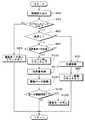
続いて、上記ECU15の制御内容について図2のフローチャートに基づき説明する。なお、このフローチャートは、上記イグニッションスイッチがオンされているときに実行される。
先ず、ステップS30では情報読み込みとして、上記センサ20〜22、24、25からの信号、および温度設定器23からの信号を読み込み記憶する。
【0022】
その後、ステップS40にて、上記エアコンスイッチ25がオンか否かを判定する。そして、エアコンスイッチ25がオフの場合は、車両用空調装置100を作動させて、車室内を空調する必要が無いので、ステップS50に進み、電動モータ9を停止、電磁クラッチ3をオフとする。これにより、コンプレッサ4は停止状態となる。
【0023】
一方、ステップS40にてエアコンスイッチ25がオンであると判定されると、ステップS60に進む。
そして、ステップS60では車速センサ24が検出する車速が0が否かが判定され、車速が0でないつまり車両走行中であると判定されると、ステップS70に進んで、上記電磁式制御弁機構4aにてコンプレッサ4の容量制御を行ったのち、ステップS70に進んで、エンジンを駆動状態とするとともに電磁クラッチ3をオンとして、コンプレッサ4を駆動する。
【0024】
ここで、ステップS70における容量制御を簡単に説明すると、先ず、上記外気温センサ20、上記内気温センサ21、日射センサ22、および温度設定器23からの信号に基づいて空調風の目標吹出温度TAOを算出する。そして、この目標吹出温度TAOに基づいて、蒸発器14を通過した直後の目標空気温度TEOを決定する。なお、この目標空気温度TEOは、図3に示すように上記目標吹出温度TAOが高くなるほど高くなるように決定される。
【0025】
そして、上記電磁式制御弁機構4aにて、温度センサ26が検出する温度が上記目標空気温度TEOとなるようにコンプレッサ4の容量が制御される。これにより、上記目標空気温度TEOが高くなるほど、コンプレッサの容量が大きくなる。このようにすることで、上記目標空気温度TEOは車室内の冷房負荷と考えられるので、冷房負荷が小さくなるとコンプレッサ4の吐出容量が小さくなって、エンジン1の負荷を低減させることができる。
【0026】
そして、本実施形態では、エンジン1を起動してコンプレッサ4を駆動する前に、先ずステップS70にて上記容量制御が行われてコンプレッサ4の容量が所定量に設定されたのち、ステップS80にてエンジン1が起動され、電磁クラッチ3がオンとなる。
一方、ステップS60にて車速が0と判定される場合、例えばトラックが目的地に到着して停止した場合、ステップS90にてクールダウン状態か否か、つまり車室内の冷房負荷(必要冷却能力)が所定値(所定の必要能力)より大きいか否かが判定される。
【0027】
ここで、本実施形態におけるステップS60の具体的な判定内容は、以下のようなものである。本実施形態では、例えば夏場のように外気温が非常に高くて、例えば外気温が30℃以上、かつ車室内の温度も高くて例えば30℃以上のときには、冷房負荷が所定値より大きいときである。言い換えると、コンプレッサ4の容量が設定可能な最大値と最低値との間の所定容量より大きいか否かを判定することでし、冷凍サイクル5の冷媒循環量が所定値より大きいか否かを判定している。なお、本実施形態でのコンプレッサ4は、容量を間接的にしか検出することができなく、上述のように外気温と内気温とによって容量を推定している。
【0028】
そして、車室内の冷房負荷が所定値より大きい場合は、車室内の冷房負荷に応じてステップS70、80と進んで、上記容量制御が行われる。
また、車室内の冷房負荷が所定値より小さい場合は、ステップS100に進んで、エンジン1が停止されるとともに、電磁クラッチ4もオフとなる。
このように本実施形態では、イグニッションスイッチ16がオンの状態で、トラックが例えば、荷物の運び先にて停車し車速が0となったときに冷房負荷が所定値より小さいと、自動的にエンジン1が停止される。例えば、トラックが目的地に到着して車両を停止して荷物を運びだすといった作業を行うときには、エンジン1を駆動させる必要が無い。そこで、本実施形態では車両が停止すると、必ずエンジン1が停止するので、上記作業中にエンジン1から排気ガスが排出されることも無く、大気を汚染することを防止できる。また、信号待ち等で車両が停止したときにも、同様にエンジン1が停止される。
【0029】
しかし、このようにエンジン1が停止されると、いままで駆動していたコンプレッサ4が停止するので、冷凍サイクル5には冷媒が循環せず車両用空調装置の冷却能力が0となって、車室内の空調を引き続き行うことができない。
そこで、本実施形態では、冷房負荷が所定値より小さいときには、電動モータ9を起動して、電動モータ9にてコンプレッサ4を駆動する。つまり、冷房負荷が所定値より小さいときには、コンプレッサ4の容量が上記所定容量より小さく、冷凍サイクル5での冷媒循環量が小さいので、コンプレッサ4を駆動するための駆動力は小さくなる。従って、この際は駆動力の小さい電動モータ9にてコンプレッサ4を駆動する。
【0030】
一方、ステップS50にてNOと判定されて冷房負荷が所定値より大きいときには、コンプレッサ4の容量も上記所定容量より大きくなるので、冷凍サイクル5での冷媒循環量が大きくなって、コンプレッサ4の駆動するための駆動力が大きくなる。従って、この場合は車両が停止しても駆動力が大きいエンジン1にて、コンプレッサ4を駆動する。
【0031】
このようにすることで、小型の電動モータ9にてコンプレッサを駆動することができ、電動モータ9の車両への搭載性を向上できる。
さらに本実施形態では、コンプレッサ4を外部可変容量タイプのものとし、冷房負荷が所定値より小さい、つまり容量が所定容量より小さいときに電動モータ9にてコンプレッサ4を駆動するので、コンプレッサ4を固定容量タイプのものとした場合より、コンプレッサ4を駆動する駆動力は小さくて済む。この結果、本実施形態では、コンプレッサ4を固定容量タイプのものとした場合より電動モータ9の体格を小さくできる。
【0032】
また、このように電動モータ9にてコンプレッサ4を駆動するのであるが、本実施形態では電動モータ9にてコンプレッサ4を駆動する前に、ステップS110のような低容量制御が行われる。
つまり、ステップS110では、強制的に電磁式制御弁機構4aにてコンプレッサ4の容量を設定可能な最低の吐出容量(低容量状態)としてから、電動モータ9を起動する。これにより、コンプレッサ4の容量が小さくなるので、コンプレッサ4の駆動するための駆動力は、容量が大きなときより小さくなる。
【0033】
従って、電動モータ9にてコンプレッサ4を駆動する際、大きな駆動力を持つ、大型な電動モータを使用しなくとも、十分コンプレッサ4を駆動できる。この結果、さらに電動モータ9の体格を小さくでき、電動モータ4の車両搭載性を格段に向上できる。
また、本実施形態では図示されていないが、一旦電動モータ9にてコンプレッサ4が駆動されると、再度エンジン1が駆動されるまでは、低容量状態が継続される。なお、この際、電動モータ9(コンプレッサ4)の回転数は一定である。
【0034】
これにより、冷凍サイクル5は、車室内を十分に冷却する必要冷却能力を発揮することができないにしても、車両の冷却をある程度継続することができる。
従って、例えば夏場にトラックが荷物を積み卸ししているとき等に、キャビンの温度上昇を低減でき、荷物積み卸し後、乗員に与える不快感を和らげることができる。
【0035】
そして、本実施形態では、ステップS130にて電動モータ9の駆動継続時間が所定時間T経過したか否かが判定され、所定時間T(例えば2分)経過したならば、ステップS140に進み、電動モータ9を停止する。これにより、電動モータ9によるバッテリ上がりを防止できる。
そして、電動モータ9にてコンプレッサ4が駆動されている状態で、再度エンジン1を駆動して車両走行を行う場合は、例えばイグニッションスイッチ16を一旦オフとし、再度イグニッションスイッチ16をオンとすることで、エンジン1が起動される。
【0036】
また、このようなエンジン1再起動時に、車速が0であると直ぐにエンジン1が停止してしまうので、一旦、イグニッションスイッチ16をオンすると所定時間は、車速が0であってもエンジン1を停止しないようにすると良い。
(第2実施形態)
上記第1実施形態では、電磁クラッチ3とプーリ6を別個に設けたが、本例では、電磁クラッチ3とプーリ6とを一体化したものである。また、本例では、コンプレッサ4を駆動する必要があるときには、電磁クラッチ3をオンとし、必要が無いときには電磁クラッチ3をオフとする。
【0037】
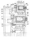
本例における電磁クラッチ3の構造を図4を用いて説明する。電磁クラッチ3は、主としてロータ41とこのロータ41と対向配置されるアーマチャ42とからなる。
ロータ41は、磁性材である鋼材(例えば、JIS規格、SPCC)にて形成されており、磁気回路を構成するものである。ロータ41は、断面コの字の円環状に形成されており、その底壁部には、磁気遮断部である空隙46が2列設けられている。
【0038】
ロータ41内には、磁気回路を構成する鋼材にて断面コの字の円環状に形成されて、ステータ43が内蔵配置されている。ステータ43内には、樹脂にてモールド固定されたコイル部55が内蔵されている。
ロータ41の内周面には、回転軸受けとしてのボールベアリング44が固定されており、さらにボールベアリング44の内周部は、コンプレッサ4のハウジング4aに固定されている。これにより、ロータ41は、ハウジング4aに対して回転可能となっている。
【0039】
ロータ41の外周側には、回転軸受けとしての2つのボールベアリング45が並ぶように固定されている。ボールベアリング45の外周側には、プーリ47が固定されており、このプーリ47には、動力伝達部材であるベルト7が巻架されている(図1参照)。また、ベルト7は、上記駆動プーリ2に巻架されている。ロータ41とプーリ47との間には、一方向しか回転しない一方向回転動力伝達機構であるワンウェイクラッチ48(本例ではスプラグ式)が配置されており、これにより、本例では、プーリ47は、図2中紙面表側から裏側に向かってのみ回転するようになっている。また、本例におけるロータ41には、図4中左側にプーリ49が一体成形されており、このプーリ49には、動力伝達部材であるベルト8が巻架されている(図1参照)。また、図1に示すようにべルト8は、電動モータ9の駆動軸に設けられた駆動プーリ10に巻架されている。
【0040】
アーマチャ42は、磁性材(例えばSPCC)にて円板環状に形成されており、磁気遮断部46が形成されたロータ41の底壁部と、所定の間隔開けて対向配置されている。アーマーチャ42には、磁気遮断部である空隙51が形成されている。
アーマチャ42は、図4に示すように環状に形成されたアウターハブ52と、リベット53にて固定されている。アウターハブ52の内周側には、インナーハブ54が配置されており、アウターハブ52とインナーハブ54とは弾性体であるゴム部材56をを加硫接着にて接着固定されている。インナーハブ54は、内周側がハウジング4aに延びており、コンプレッサ4のシャフト4bがはめ込まれている。
【0041】
そして、このように構成された電磁クラッチ3は、上記コイル部55に通電が施されると、アーマチャ42が図4中右側に吸着されると、プーリ47もしくはプーリ49に動力が伝わっているかによって、コンプレッサ4の駆動源が変わる。
例えば、エンジン1が駆動して、駆動プーリ2が駆動している場合には、ベルト7に動力が伝わり、プーリ47が回転する。そして、このプーリ47に伝わった動力は、ワンウェイクラッチ48を通じて、ロータ41が回転する。従って、アーマーチャ42が回転し、この動力がゴム部材56を通じて、インナーハブ54に伝わり、シャフト4bが回転する。この結果、コンプレッサ4が駆動される。なお、この際、プーリ49も回転する。
【0042】
一方、エンジン1が停止されて、電動モータ9が駆動された場合では、ロータ41が回転し、アーマチャ42も回転するため、コンプレッサ4が駆動される。なお、この場合、プーリ47はワンウェイクラッチ48によって空回りするため、駆動プーリ2を回転させない。このため、電動モータ8に余分な仕事をさせる必要が無い。
【0043】
(第3実施形態)
本例では、上記ワンウェイクラッチ48の代わりに電磁クラッチ機構を設けたものである。以下、図5に基づき説明する。
ボールベアリング45の外周側には、断面コの字のロータ58が設けられており、このロータ58の底壁には、磁気遮断部である空隙59が形成されている。ロータ58には、プーリ47が一体成形されている。ロータ内58には、コイル部61を内蔵する断面コの字状のステータ62が配置されている。ロータ58と吸着するアーマチャ63は、ロータ58の空隙59が形成された底壁部と対向配置されている。
【0044】
アーマチャ63は、リベット64にてアウターハブ65と固定されており、アウターハブ65とロータ41の外周部とは、弾性体であるゴム部材66による加硫接着にて接着固定されている。
このような構成により、コイル部55のみに通電を施すと、ロータ41とアーマチャ42とが吸着し、プーリ49のみが回転し、電動モータ9にてコンプレッサ4が駆動される。また、コイル部55およびコイル部61の両方に通電を施すと、ロータ41とアーマチャ42とが吸着するとともに、ロータ58とアーマチャ63とが吸着する。このため、プーリ47からの動力がアーマチャ63に伝わり、さらにアーマチャ63からロータ41に伝わる。ロータ41に伝わった動力は、アーマチャ42に伝わるので、コンプレッサ4が駆動されることになる。
【0045】
(他の実施形態)
上記実施形態では、上記冷凍サイクル5は車両のキャビンを冷却するためのものであったが、例えば冷凍車や冷蔵車用のものであっても良い。この場合、車両が停止して、荷物を運び出すといった作業を行うときに冷凍室や冷蔵室の冷却が継続して行える。
【0046】
また、さらに本発明は、走行条件に応じて電動モータもしくはエンジンにて走行可能な、所謂ハイブリッド車に適用しても良い。
また、さらに本発明は、発電専用のエンジンを搭載し、このエンジンにて発電された電力にて電動モータを駆動し、この電動モータを走行駆動源とする車両に適用しても良い。
【0047】
また、上記各実施形態では、電動モータ9の回転数を一定としたが、例えば冷房負荷に応じて回転数を可変するようにしても良い。
【0048】
また、上記各実施形態では冷房負荷を判定する要素として、外気温や内気温を用いたが、上記目標吹出温度TAO、目標空気温度TEO値であっても良い。さらにコンプレッサ4の吸入圧力と吐出圧力によってコンプレッサ4の容量を推定しても良い。
また、上記各実施形態では、コンプレッサ4を外部から容量が可変可能なものについて説明したが、本発明は固定容量のコンプレッサであっても良いし、スクロールタイプ、ベーンタイプのコンプレッサであっても良い。
【図面の簡単な説明】
【図1】本発明の第1〜第3実施形態における車両用ハイブリッドコンプレッサの全体システム図である。
【図2】上記各実施形態おけるECU15の制御内容を表すフローチャートである。
【図3】上記各実施形態おける目標吹出温度TAOと目標空気温度TEOとの関係を表す図である。
【図4】上記第2実施形態おける電磁クラッチの構造を示す断面図である。
【図5】上記第3実施形態おける電磁クラッチの構造を示す断面図である。
【符号の説明】
1…エンジン、4…コンプレッサ、5…冷凍サイクル、9…電動モータ、
15…ECU。[0001]
TECHNICAL FIELD OF THE INVENTION
The present invention relates to a control device for a vehicle hybrid compressor that selectively drives a compressor using two power sources.
[0002]
[Prior art]
Normally, in a vehicle, a compressor of a vehicle air conditioner is driven by an engine. Therefore, when the engine is stopped, the compressor stops and air conditioning in the vehicle compartment cannot be performed. Then, in this case, when the engine is stopped, a compressor that is driven by an electric motor to continue air conditioning in the vehicle compartment has been considered.
[0003]
[Problems to be solved by the invention]
However, the conventional device has the following problems. In the above, when trying to drive the compressor with the electric motor at the same level as the engine, for example, when the cooling load such as cooling the vehicle interior rapidly in summer or the like is very large, the driving force for driving the compressor is large. Therefore, a large electric motor having a large driving force corresponding to this must be used. As a result, there is a problem that the mountability of the electric motor on the vehicle is deteriorated.
[0004]
Therefore, an object of the present invention is to reduce the size of an electric motor and improve the mountability of a compressor on a vehicle.
[0005]
[Means for Solving the Problems]
The present invention employs the following technical means to achieve the above object.
According to the first to sixth aspects of the present invention, there is provided a determining means (S90) for determining whether the required cooling capacity in the refrigeration cycle (5) is smaller than a predetermined required capacity. When the cooling capacity is larger than the predetermined required capacity, the compressor (1) is driven by the engine (1), and when the required cooling capacity is smaller than the predetermined required capacity, the electric motor (9) is determined by the determining means (S90). To drive the compressor (1).
[0006]
As a result, when the compressor is driven by the electric motor, the required cooling capacity is smaller than the predetermined required capacity. At this time, the amount of circulating refrigerant in the refrigeration cycle is small, so that the driving force for driving the compressor is reduced. Therefore, in this case, the compressor can be driven by an electric motor having a small driving force.
On the other hand, when the required cooling capacity is larger than the predetermined required capacity, the amount of circulating refrigerant in the refrigeration cycle increases, and the driving force for driving the compressor increases. Therefore, in this case, even when the engine is stopped, the compressor is driven by the engine having a large driving force.
[0007]
As a result, the compressor can be driven by the small electric motor, and the mountability of the electric motor on the vehicle can be improved.
According to the third aspect of the invention, when the displacement controlled by the displacement control means (4a, 15) is smaller than a predetermined displacement, the compressor (4) is driven by the electric motor (9), Is larger than the predetermined capacity, the engine (1) controls the compressor (4).
[0008]
Thus, when the capacity of the compressor is smaller than the predetermined capacity, the driving force for driving the compressor can be small, and in this case, the compressor is driven by the electric motor. On the other hand, when the capacity of the compressor is larger than the predetermined capacity, the driving force for driving the compressor is large. In this case, the compressor is driven by the engine.
[0009]
Thus, the size of the electric motor can be made smaller than when the compressor is of a fixed displacement type. As a result, the vehicle mountability of the electric motor can be further improved.
Further, in the invention described in
[0010]
Accordingly, when the compressor is driven before the electric motor is started, the capacity of the compressor is set to a low capacity state smaller than the predetermined value, so that the driving force for driving the compressor is smaller than when the capacity is large. Therefore, when the compressor is driven by the electric motor, the compressor can be sufficiently driven by the small electric motor without using a large electric motor having a large driving force. As a result, the size of the electric motor can be further reduced, and the mountability of the electric motor on a vehicle can be significantly improved.
[0011]
BEST MODE FOR CARRYING OUT THE INVENTION
(1st Embodiment)
Hereinafter, embodiments of the present invention will be described with reference to FIGS. In this embodiment, the present invention is applied to a vehicle that carries out a load such as a truck. Further, in the truck according to the present embodiment, the engine is stopped when the vehicle stops, in order to prevent the luggage from being carried out while the engine is driven.
[0012]
FIG. 1 is an overall system diagram of a drive device of a vehicle hybrid compressor according to the present embodiment.
Reference numeral 1 denotes an engine that is a traveling drive source mounted on a vehicle. A drive pulley 2 is provided on an output shaft of the engine 1, and the drive pulley 2 is configured to rotate in conjunction with driving of the engine 1. Reference numeral 3 denotes a well-known electromagnetic clutch as power intermittent means, and
[0013]
A pulley 6 is provided on a drive shaft of the
[0014]
The
[0015]
Here, the
First, in the present embodiment, the
[0016]
The
[0017]
The
[0018]
The above-described electromagnetic clutch 3,
The
[0019]
The
[0020]
Also, the
The
[0021]
Next, the control contents of the
First, in step S30, as information reading, the signals from the
[0022]
Thereafter, in step S40, it is determined whether the
[0023]
On the other hand, if it is determined in step S40 that the
In step S60, it is determined whether or not the vehicle speed detected by the
[0024]
Here, the capacity control in step S70 will be briefly described. First, based on the signals from the outside
[0025]
The capacity of the
[0026]
In the present embodiment, before the engine 1 is started and the
On the other hand, if the vehicle speed is determined to be 0 in step S60, for example, if the truck arrives at the destination and stops, it is determined in step S90 whether or not the vehicle is in the cool-down state, that is, the cooling load (required cooling capacity) Is larger than a predetermined value (predetermined required capacity).
[0027]
Here, the specific determination content of step S60 in the present embodiment is as follows. In the present embodiment, for example, when the outside air temperature is extremely high, for example, in the summer, for example, when the outside air temperature is 30 ° C. or more, and when the temperature inside the vehicle compartment is also high, for example, 30 ° C. or more, when the cooling load is larger than a predetermined value is there. In other words, it is determined whether or not the capacity of the
[0028]
If the cooling load in the vehicle compartment is larger than the predetermined value, the process proceeds to steps S70 and S80 according to the cooling load in the vehicle compartment, and the above-described capacity control is performed.
If the cooling load in the passenger compartment is smaller than the predetermined value, the process proceeds to step S100, where the engine 1 is stopped and the
As described above, in this embodiment, when the
[0029]
However, when the engine 1 is stopped in this way, the
Therefore, in the present embodiment, when the cooling load is smaller than the predetermined value, the electric motor 9 is started and the
[0030]
On the other hand, when it is determined as NO in step S50 and the cooling load is larger than the predetermined value, the capacity of the
[0031]
By doing so, the compressor can be driven by the small electric motor 9, and the mountability of the electric motor 9 on the vehicle can be improved.
Further, in this embodiment, the
[0032]
In addition, the
That is, in step S110, the electric motor 9 is started after forcibly setting the capacity of the
[0033]
Therefore, when the
Although not shown in the present embodiment, once the
[0034]
Thus, the
Therefore, for example, when the truck is loading and unloading the luggage in summer, the temperature rise in the cabin can be reduced, and the discomfort given to the occupant after the unloading of the luggage can be reduced.
[0035]
Then, in the present embodiment, it is determined whether or not the drive continuation time of the electric motor 9 has passed a predetermined time T in step S130. If the predetermined time T (for example, 2 minutes) has passed, the process proceeds to step S140, and the electric motor 9 is driven. The motor 9 is stopped. This can prevent the battery from running down due to the electric motor 9.
When the vehicle is driven by driving the engine 1 again while the
[0036]
In addition, when the engine 1 is restarted, if the vehicle speed is 0, the engine 1 stops immediately. Therefore, once the
(2nd Embodiment)
In the first embodiment, the electromagnetic clutch 3 and the pulley 6 are provided separately, but in this example, the electromagnetic clutch 3 and the pulley 6 are integrated. In this example, when the
[0037]
The structure of the electromagnetic clutch 3 in this embodiment will be described with reference to FIG. The electromagnetic clutch 3 mainly includes a
The
[0038]
Inside the
A
[0039]
Two
[0040]
The
The
[0041]
When power is applied to the
For example, when the engine 1 is driven and the drive pulley 2 is driven, power is transmitted to the belt 7 and the
[0042]
On the other hand, when the electric motor 9 is driven with the engine 1 stopped, the
[0043]
(Third embodiment)
In this embodiment, an electromagnetic clutch mechanism is provided instead of the one-
A
[0044]
The
With such a configuration, when current is applied only to the
[0045]
(Other embodiments)
In the above embodiment, the
[0046]
Further, the present invention may be applied to a so-called hybrid vehicle that can run with an electric motor or an engine according to running conditions.
Further, the present invention may be applied to a vehicle in which an engine dedicated to power generation is mounted, an electric motor is driven by electric power generated by the engine, and the electric motor is used as a driving source.
[0047]
Further, in each of the above embodiments, the rotation speed of the electric motor 9 is fixed, but the rotation speed may be varied according to, for example, a cooling load.
[0048]
Further, in each of the above embodiments, the outside air temperature and the inside air temperature are used as the element for determining the cooling load. Further, the capacity of the
Further, in each of the above embodiments, the
[Brief description of the drawings]
FIG. 1 is an overall system diagram of a vehicle hybrid compressor according to first to third embodiments of the present invention.
FIG. 2 is a flowchart showing control contents of an
FIG. 3 is a diagram illustrating a relationship between a target air temperature TAO and a target air temperature TEO in each of the above embodiments.
FIG. 4 is a cross-sectional view illustrating a structure of an electromagnetic clutch according to the second embodiment.
FIG. 5 is a cross-sectional view showing a structure of an electromagnetic clutch according to the third embodiment.
[Explanation of symbols]
1 ... Engine, 4 ... Compressor, 5 ... Refrigeration cycle, 9 ... Electric motor,
15 ... ECU.
Claims (6)
Translated fromJapanese前記冷凍サイクル(5)での必要冷却能力が所定の必要能力より小さいか否かを判定する判定手段(S90)を有し、
前記判定手段(S90)により、前記必要冷却能力が所定の必要能力より大きいと判定されたときには、前記エンジン(1)にて前記コンプレッサ(4)を駆動し、前記判定手段(S90)により、前記必要冷却能力が所定の必要能力より小さいと判定されたときには、前記電動モータ(9)にて前記コンプレッサ(4)を駆動することを特徴とする車両用ハイブリッドコンプレッサの制御装置。A vehicle hybrid configured to drive a compressor (1) of a refrigeration cycle (5) of a vehicle by one of an engine (1) mounted on the vehicle and an electric motor (9) mounted on the vehicle. In the compressor control device,
Determining means (S90) for determining whether the required cooling capacity in the refrigeration cycle (5) is smaller than a predetermined required capacity;
When the determination means (S90) determines that the required cooling capacity is larger than a predetermined required capacity, the engine (1) drives the compressor (4), and the determination means (S90) determines that the compressor (4) is driven. A controller for a vehicle hybrid compressor, wherein the compressor (4) is driven by the electric motor (9) when it is determined that the required cooling capacity is smaller than a predetermined required capacity.
前記外部可変容量コンプレッサの容量を、冷却環境情報(TEO)に基づいて制御する容量制御手段(4a、15)を有することを特徴とする請求項1記載の車両用ハイブリッドコンプレッサの制御装置。The compressor (4) is constituted by an external variable displacement compressor whose capacity can be arbitrarily varied from outside,
The control device for a vehicle hybrid compressor according to claim 1, further comprising a capacity control unit (4a, 15) for controlling a capacity of the external variable capacity compressor based on cooling environment information (TEO).
前記容量制御手段(4a、15)にて制御される前記容量が所定の容量より小さいか否かを判定し、前記容量が前記所定の容量より小さいときには、前記電動モータ(9)にて前記コンプレッサ(4)を駆動し、前記容量が前記所定の容量より大きいときには、前記エンジン(1)にて前記コンプレッサ(4)を制御することを特徴とする請求項2記載の車両用ハイブリッドコンプレッサの制御装置。The determining means (90)
It is determined whether or not the capacity controlled by the capacity control means (4a, 15) is smaller than a predetermined capacity. When the capacity is smaller than the predetermined capacity, the compressor is controlled by the electric motor (9). The control device for a vehicle hybrid compressor according to claim 2, wherein (4) is driven, and when the capacity is larger than the predetermined capacity, the compressor (4) is controlled by the engine (1). .
前記スイッチ手段(16)にて前記車両が走行可能に設定されているときに、前記車両が停止し、かつ前記必要冷却能力が所定の必要能力より小さいと、前記エンジン(1)を停止して、前記電動モータ(9)にて前記コンプレッサ(4)を駆動することを特徴とする請求項1ないし5のいずれか1つに記載の車両用ハイブリッドコンプレッサの制御装置。Switch means (16) for setting the vehicle to be able to travel,
When the vehicle is set to be runnable by the switch means (16), the vehicle is stopped, and if the required cooling capacity is smaller than a predetermined required capacity, the engine (1) is stopped. The control device for a vehicle hybrid compressor according to any one of claims 1 to 5, wherein the compressor (4) is driven by the electric motor (9).
Priority Applications (3)
| Application Number | Priority Date | Filing Date | Title |
|---|---|---|---|
| JP25115097AJP3555404B2 (en) | 1997-02-24 | 1997-09-16 | Control device of hybrid compressor for vehicle |
| US09/007,661US5867996A (en) | 1997-02-24 | 1998-01-15 | Compressor control device for vehicle air conditioner |
| DE19807326ADE19807326A1 (en) | 1997-02-24 | 1998-02-20 | Compressor control device for automobile air-conditioning device |
Applications Claiming Priority (3)
| Application Number | Priority Date | Filing Date | Title |
|---|---|---|---|
| JP9-39495 | 1997-02-24 | ||
| JP3949597 | 1997-02-24 | ||
| JP25115097AJP3555404B2 (en) | 1997-02-24 | 1997-09-16 | Control device of hybrid compressor for vehicle |
Publications (2)
| Publication Number | Publication Date |
|---|---|
| JPH10291415A JPH10291415A (en) | 1998-11-04 |
| JP3555404B2true JP3555404B2 (en) | 2004-08-18 |
Family
ID=26378909
Family Applications (1)
| Application Number | Title | Priority Date | Filing Date |
|---|---|---|---|
| JP25115097AExpired - Fee RelatedJP3555404B2 (en) | 1997-02-24 | 1997-09-16 | Control device of hybrid compressor for vehicle |
Country Status (1)
| Country | Link |
|---|---|
| JP (1) | JP3555404B2 (en) |
Families Citing this family (11)
| Publication number | Priority date | Publication date | Assignee | Title |
|---|---|---|---|---|
| JP2002081375A (en)* | 2000-09-06 | 2002-03-22 | Zexel Valeo Climate Control Corp | Hybrid compressor |
| JP4669640B2 (en)* | 2001-08-22 | 2011-04-13 | サンデン株式会社 | Air conditioner for vehicles |
| JP3855866B2 (en)* | 2001-12-26 | 2006-12-13 | 株式会社デンソー | Hybrid compressor device |
| JP4114420B2 (en) | 2002-07-12 | 2008-07-09 | 株式会社デンソー | Hybrid compressor and control device thereof |
| JP2004256045A (en) | 2003-02-27 | 2004-09-16 | Calsonic Kansei Corp | Hybrid compressor system |
| JP4376651B2 (en)* | 2003-03-17 | 2009-12-02 | サンデン株式会社 | Air conditioner for vehicles |
| US8381540B2 (en) | 2006-11-15 | 2013-02-26 | Crosspoint Solutions, Llc | Installable HVAC systems for vehicles |
| US7797958B2 (en) | 2006-11-15 | 2010-09-21 | Glacier Bay, Inc. | HVAC system controlled by a battery management system |
| US8030880B2 (en) | 2006-11-15 | 2011-10-04 | Glacier Bay, Inc. | Power generation and battery management systems |
| US8863540B2 (en) | 2006-11-15 | 2014-10-21 | Crosspoint Solutions, Llc | HVAC system controlled by a battery management system |
| FR2958340B1 (en)* | 2010-03-31 | 2013-06-07 | Valeo Sys Controle Moteur Sas | METHOD FOR DETERMINING THE POWER OF AN ELECTRIC MOTOR OF A HYBRID COMPRESSOR |
- 1997
- 1997-09-16JPJP25115097Apatent/JP3555404B2/ennot_activeExpired - Fee Related
Also Published As
| Publication number | Publication date |
|---|---|
| JPH10291415A (en) | 1998-11-04 |
Similar Documents
| Publication | Publication Date | Title |
|---|---|---|
| US5867996A (en) | Compressor control device for vehicle air conditioner | |
| JP5668700B2 (en) | Vehicle air conditioning system | |
| JP5532029B2 (en) | Air conditioner for vehicles | |
| JP5668704B2 (en) | Vehicle air conditioning system | |
| US6755033B2 (en) | Hybrid compressor apparatus and method of controlling the same | |
| JP2003326962A (en) | Vehicle air conditioner | |
| WO2011105051A1 (en) | Vehicle air conditioner device | |
| JPH115439A (en) | Air-conditioning device for vehicle | |
| JP2004026132A (en) | Hybrid air conditioning system for motor direct connection type vehicle and control method therefor | |
| WO2013021753A1 (en) | Vehicle air-conditioner apparatus | |
| JP3555404B2 (en) | Control device of hybrid compressor for vehicle | |
| JP2004189175A (en) | Air conditioner for vehicle | |
| JP3697817B2 (en) | Control device for vehicle compressor | |
| US7207784B2 (en) | Hybrid compressor and control device | |
| WO2017138258A1 (en) | Vehicular air-conditioning device | |
| KR101757264B1 (en) | Air conditioner for vehicle | |
| JP2002370529A (en) | Air-conditioner for vehicle | |
| JP3624617B2 (en) | Air conditioner for vehicles | |
| US20080041078A1 (en) | Method of controlling air conditioner in hybrid car | |
| WO2012043062A1 (en) | Vehicle air-conditioning device | |
| JPH11139155A (en) | Air conditioner for vehicle | |
| JP2004249897A (en) | Air conditioner for vehicle | |
| JP6443054B2 (en) | Air conditioner for vehicles | |
| JPH11254955A (en) | Vehicle air-conditioner | |
| JP3951807B2 (en) | Air conditioner for vehicles |
Legal Events
| Date | Code | Title | Description |
|---|---|---|---|
| A977 | Report on retrieval | Free format text:JAPANESE INTERMEDIATE CODE: A971007 Effective date:20040331 | |
| TRDD | Decision of grant or rejection written | ||
| A01 | Written decision to grant a patent or to grant a registration (utility model) | Free format text:JAPANESE INTERMEDIATE CODE: A01 Effective date:20040420 | |
| A61 | First payment of annual fees (during grant procedure) | Free format text:JAPANESE INTERMEDIATE CODE: A61 Effective date:20040503 | |
| R150 | Certificate of patent or registration of utility model | Free format text:JAPANESE INTERMEDIATE CODE: R150 | |
| FPAY | Renewal fee payment (event date is renewal date of database) | Free format text:PAYMENT UNTIL: 20110521 Year of fee payment:7 | |
| FPAY | Renewal fee payment (event date is renewal date of database) | Free format text:PAYMENT UNTIL: 20120521 Year of fee payment:8 | |
| FPAY | Renewal fee payment (event date is renewal date of database) | Free format text:PAYMENT UNTIL: 20120521 Year of fee payment:8 | |
| FPAY | Renewal fee payment (event date is renewal date of database) | Free format text:PAYMENT UNTIL: 20130521 Year of fee payment:9 | |
| LAPS | Cancellation because of no payment of annual fees |